1. Introduction
Highly loaded, oscillating, grease-lubricated rolling element bearings play a role in several technical applications. In comparison to oil lubrication, the analysis of grease lubrication can require specialised treatment [
1]. Furthermore, the wear and fatigue behaviour of these bearings is mostly discussed in the context of blade bearings in wind turbines especially for those operated with an individual pitch controller (IPC) [
2,
3,
4,
5]. Load-mitigating controller design leads to a highly increased pitch activity [
6]. Thus, the question arises whether frequent pitching can lead to critical damage in these bearings as is the case in small-scale laboratory testing or field failures such as false brinelling. Damage marks in oscillating bearings are physically distinguished by the ratio of the travelled distance by the rolling element on the raceway between the upper and lower dead centre of the oscillation
x to the width of the contact
parallel to the direction of rolling. If the ratio
, there are points on the raceway that are constantly part of the mechanical contact as long as the centre of the oscillation does not change. Under these conditions, a sticking zone usually emerges in the middle of the contact in which no relative motion between the contacting surfaces occurs. Therefore, the damage marks caused by these conditions show a distinctive central zone that is exempted from any wear due to the locally lacking relative motion that leads to adhesive or abrasive surface damage. In the following, these marks are called standstill marks since the described contact conditions often occur due to vibrations during the standstill of the bearing [
7]. Nevertheless, there is no consensus on the naming in the literature [
8,
9,
10,
11].
On the other hand, operating conditions with
provoke wear marks of a more uniform appearance. Mostly, they are referred to as false brinelling since the damage marks in an advanced stadium can be mistaken for indentation due to plastic deformation similar to the Brinell hardness test [
7]. The investigations in this paper focus solely on the mechanism of false brinelling, i.e., fully open contacts. In comparison to standstill marks, there is less literature on the influence of the main oscillation parameters, namely the frequency
f and the double amplitude of the inner ring
(in the case of a locked outer ring). Phaner-Goutorbe et al. [
12] tested grease-lubricated TBB with frequencies from 3 to 20 Hz and double amplitudes between
and
. They reported that, in this range, there was no significant difference in wear progress for the different parameter combinations of
f and
. There is no further comment on how this was judged. Although their STM-scans provide interesting insight into the process of damage development, information regarding friction torque and lubrication mechanisms are not directly provided. Maruyama et al. [
13] used a similar test setup to investigate the mechanisms behind oil and grease lubrication under
-ratios from
to 2. For
, they observe that the influence of the maximum rolling speed (2 to
) on the extent of the wear varies with the kinematic viscosity of the base oil. They judged the extent with an indicator formed by taking the ratio of the final surface roughness to the initial surface roughness. For thick base oils (
), this indicator increased with higher speeds. Greases with thinner base oils (
) showed the opposite behaviour for increasing maximum rolling velocities during an oscillation period. It is not fully clear whether conclusions regarding the wear measured by the change in surface roughness are compatible with other means of measuring wear such as weight loss or increase in friction torque. Moreover, the range of values of the
-ratio from
to 2 covered by their experiments is relatively small and close to standstill marks, which are not the focus of this publication. Becker [
14] showed that there is a strong correlation between an increase in friction torque and the indentation depth of damage marks. He compared the performance of different greases with and without additional contamination of salt water. Experimental investigations on the influence of the oscillation parameters were not mentioned. Cavacece et al. [
15] investigated the oscillating endurance of a spherical roller bearing under a frequency of 5 Hz and an oscillation double amplitude of
. There is no comment on the kind of grease they used in their investigations with a maximum contact pressure of 4 GPa. They characterised damage evolution using the variation of the progression of the resistant torque over the course of an experiment and SEM scans. After smoothing during a run-in phase, the surfaces of a roller and raceway start to show detachments of the surface and plastic deformations. Continuing the experiment leads to deep pittings on the raceway surface. They compared their results to previous work of theirs dealing with DGBB [
16]. Generally, they were able to identify the same phases in the resulting friction torque and similar changes on the raceway surfaces for both bearing types. The influence of frequency and double amplitude of the oscillating motion on the wear initiation was not addressed. Some publications with
focus on the effect of grease composition and build-up of tribolayers [
17,
18,
19,
20]. Since this paper is focused more on the influence of oscillating operating conditions, e.g., induced by pitch controllers, these results dealing with tribolayer buildup and grease properties are not further discussed. In the literature presented so far, the phenomenological course of the damage is already well documented. Comprehensive studies on the influence of the oscillation parameters on the initiation of the damage are not to be found, especially for higher
ratios. These points are of particular interest for the evaluation of pitch controllers or slewing bearing concepts for wind turbines.
A first systematic evaluation of the effect of the oscillation parameters on the friction torque was conducted by Wandel et al. [
21]. They investigated oscillating ACBB of the designation 7208 acc. to [
22,
23] (pitch diameter 60 mm) with two different greases under double amplitudes from 2 to
and frequencies from
to 5 Hz. The tests were evaluated in terms of the friction torque and showed a clear result regarding the influence of the oscillation parameters. Higher frequencies lead to a more severe damage, mostly independent of the actual double amplitude. The amplitude influence is threefold: up to a certain amplitude, the damage increases with higher angles. Beyond this threshold, further increase in amplitude reduces bearing damage. After reaching a second threshold, no more wear is observed. Wandel et al. assume that the root cause for wear under greased oscillating conditions is a mechanism similar to starvation for rolling conditions, i.e., a lack of lubricant around the contact area [
24]. The base oil on the rolling track that was released by the thickener structure is displaced by the rolling elements due to their oscillating motion and partly removed from the path of the contact. A counteracting flow driven by capillary forces around the rolling element brings new oil into the contact. If the displacement flow outweighs the replenishing flow, the initial amount of base oil around the contact will diminish with an increasing cycle number. When a critical amount of remaining base oil is undershot, the remaining base oil is not able to prevent adhesive wear between the rolling partners in the presumably prevailing boundary or mixed lubrication regime. Based on their experimental observations and the described concept, Wandel et al. propose the following empirical, dimensionless number to approximate the occurrence of the observed starvation condition (predominance of displacement flow):
The number consists of two terms: A double amplitude-dependent term and a term representing the capillary-driven replenishing flow. The numerator of the latter part consists of the base oil viscosity
, half of the contact length perpendicular to the rolling direction
a, and the oscillation frequency
f since an increase in these values hinders the base oil reflow into the track. The opposite goes for the variables in the denominator, i.e., bleeding rate
and the surface tension between the oil and air phase
. To describe the mentioned amplitude effect, a second term depending on the amplitude, i.e., the travelled distance of the rolling element between the dead centres,
x, is introduced. The travelled distance for the double amplitude at which the drop in wear initiation sets in is called
. In the first regime below this threshold, the displaced volume per cycle increases with this distance. Above the limit, the number is modified in a manner that lowers the SN-number again. Wandel et al. explain the diminished wear initiation by relubrication through cage interaction. Finally, a further increase in amplitude, and therefore, the travelled distance
x leads to the prevention of the measurable wear because relubrication by cage immersion effects dominates from this point onward. Correspondingly, there is an upper threshold
implemented into the starvation number. To summarise, the SN-number can be interpreted as a ratio between the displacing and the replenishing flows around the contact. High values, therefore, lead to a higher risk of damage initiation. In a further publication, Wandel et al. [
25] verify their proposed starvation number by testing three model greases with substantial differences regarding oil bleeding and base oil viscosity.
As Wandel et al. did previously, this paper focuses on
ratios greater than one and moderate frequencies from
to 5 Hz to be in a parameter range relevant to wind turbine blade bearings. They already proved experimentally that the proposed starvation number shows reliable results for different amplitudes, frequencies, and grease properties under small-scale laboratory conditions for point contacts. This investigation addresses the following issues regarding the work of Wandel et al.: validity for other bearing types, verification regarding the contact length
, and scalability, especially to larger bearings. Therefore, experiments with CRTBs (designation 81212) with a considerably higher contact length
but of similar size (pitch diameter 77.5 mm) to the 7208, as well as significantly larger scaled blade bearings (SBB) with a pitch diameter of 673 mm are compared. Additionally, another small-scale ACBB type with the designation 7312 acc. to [
22,
23] (pitch diameter 95 mm) with a larger ball diameter (22.23 mm vs. 11.86 mm) is tested to obtain a larger data set. The general aim of the investigation is to fill the gap in the literature regarding the influence of double amplitude and frequency on the wear initiation and lubrication supply of grease-lubricated, highly loaded, oscillating rolling element bearings at slow maximum entrainment speeds. The investigations by Wandel et al. considered only one bearing type at a small geometric scale but provided a type of analysis that invites generalisation to larger scales and for other contact geometries. In the following, we consider these generalisations precisely to investigate whether the starvation number can be used more generally as a tool for large-scale blade bearings in wind turbines of different geometries.
2. Materials and Methods
This section describes the basic testing procedure, the bearing types tested and the associated test rigs, as well as the evaluation of the obtained measurement data.
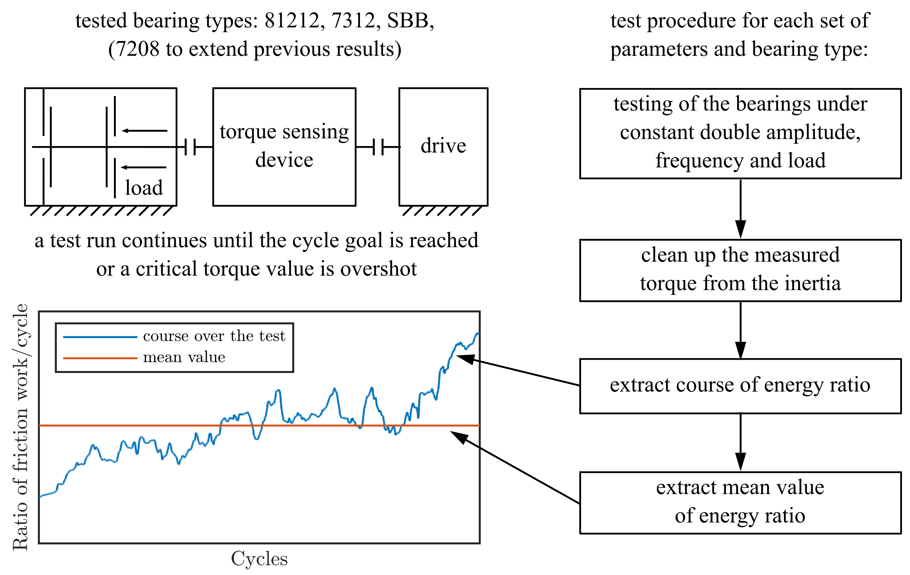
Figure 1 summarises the experimental procedure graphically. Since the experimental concept for all of the four tested bearing types is the same, a brief general description is given before a more detailed explanation of each test rig follows. In all conducted experiments, the inner ring of the bearing is subjected to a sinusoidal motion by a drive, while the outer ring is fixed. The bearing is stressed by a constant load and lubricated by a defined amount of fully formulated industrial grease. Due to the design of the test rig, two bearings are always tested simultaneously. Both bearings experience the same operating conditions and should produce the same torque and wear, but it is not possible to distinguish their results in the measurements from the test rig. For all experiments, the same grease with the properties listed in
Table 1 was used. To mimic different operating conditions, the drive is capable of performing the sinusoidal motion of the inner ring with different frequencies
f and double amplitudes
. Both are kept constant during one test run. During the experiment, the rotation angle of the inner rings and the drive torque of the bearings are recorded by corresponding measurement devices. An experiment continues until a predefined number of oscillation periods is reached or until a critical drive torque is exceeded. Load and experimental parameters for all bearing types are shown in
Table 2.
Point contacts on a small scale were tested by the use of ACBBs with the designation 7208 identical to
Wandel et al. to complement their experiments. The appointed test rig is described in more detail in their publication [
21]. To compare between line and point contact, CRTBs with the designation 81212 were tested on the test rig depicted in
Figure 2. Aside from the bearing unit itself, it is identical to the rig used for the 7208 bearings. A backlash-free-coupled servo motor subjects the bearings to sinusoidal oscillation. A torque measurement shaft between the motor and the shaft of the test unit records the inner ring rotation angle and torque. The test unit for the 81212 bearings is a modified version of the FE8 testing machine [
27] and consists of two CRTBs as test objects and two radial support bearings that bear the weight of the shaft. The test bearings are centrally loaded with an axial force applied by compressing a set of disc springs under a hydraulic press. A load cell during pressing enables one to set the desired axial force. To test the 7312 bearings, the same test unit with different bearing supports is employed. The 7208, the 7312, and the 81212 bearings are all unsealed. The grease is applied on the raceways during assembly. Before applying the sinusoidal motion of the actual test to the small-scale bearings (7208, 7312, 81212), a short rotational run-in at 10 rpm takes place for two minutes to distribute the grease in the bearing. The maximum contact pressure in all small-sized bearings is 2 GPa. The relative measurement uncertainty of the torque measuring shaft is
for the small-scale bearings.
The 4-point contact double-row bearings are tested on the BEAT1.1 (Bearing Endurance and Acceptance Test Rig 1.1) (see
Figure 3). These bearings are smaller than modern blade bearings, but built with the same topology. In addition, the manufacturing processes are the same as for real-scale blade bearings. Hence, the surface finish, hardening processes and the overall stiffness of the bearings are comparable with real blade bearing applications. They also have a similar sealing technology to the large-scale bearings. Therefore, they are referred to as scaled blade bearings (SBB) in the following. The BEAT1.1 makes use of a hexapod construction and is able to apply loads at six degrees of freedom. Therefore, the design is particularly suitable for emulating load conditions that are typical for blade bearings of wind turbines. The test rig tests two bearings at the same time in back-to-back configuration. The inner rings of both bearings are coupled with a force-transmitting element, which also holds a gearing and is connected to an electrical pitch system. This system consists of a gearbox, a torque meter and an electric motor to enable the turning movement of the bearings’ inner rings. Thus, not only the torque of the bearings is measured but also the friction torque from the gearbox. To obtain measurements dedicated to the bearings, the measured torque has to be adjusted to eliminate the influence of the gearbox. A detailed description of this procedure is given in [
28]. After assembling two test bearings to the test rig, each pair of bearings is tested with three different test programs to assess their individual friction torque properties. These test programs perform a total of 454 movements with
at different speeds and load conditions. In addition to the friction torque evaluation of the undamaged bearings, these test programs are considered a suitable running in the procedure. Hence, the grease is properly distributed, and each segment of the raceways and each rolling element has undergone some overrollings before the wear-relevant cyclic test program with sinusoidal movements is applied to the bearings. In contrast to the experiments with the smaller bearings, a static bending moment is applied to the test bearings instead of a static axial force. The bending moment is set to
= 150 kNm, which leads to a maximum pressure of 2.5 GPa in the compression and traction sides of the bearing. The idea behind this test set-up is to achieve a nonuniform load distribution on the raceways to be able to study the influence of the contact pressure on the wear development. All information given with respect to the scaled blade bearings and oscillating movements will focus on the contact properties and ratios determined at the highest contact pressure.
To evaluate an experiment for a specific parameter combination of frequency
f and double amplitude
with regard to damage development and progression based on the frictional torque, the recorded measurement signal must still be processed. The recorded signal of the torque sensing devices
from all test rigs can be split into several components:
where
T is the desired friction torque of the test bearings, and
is the acceleration torque due to the oscillating motion of the rotating parts dependent on the current angular position
. The friction torque of the potential support bearings of the test rig (only used for CRTB 81212) and other sources of friction not originating from the tested rolling contacts are summarised in
. The acceleration torque can be obtained directly from the reduced moment of inertia of all rotating parts
, and the measured angular acceleration
if the torsional stiffness of the torque transferring components is negligible. The inertia
I of the individual rotating parts is determined by a CAD-software and subsequently reduced to the speed of the inner ring according to the transmission ratios of the bearings. By assuming the torque of the support bearing is negligible, the desired friction torque of the test bearings can be determined from the measured variables in this manner:
By plotting the friction torque over the rotation angle for each period of the sinusoidal angle signal, one can obtain hysteresis loops such as in
Figure 4a. A test run with
n cycles will yield
n hysteresis loops correspondingly. Since considering all loops for each experiment individually is cumbersome when it comes to comparing the results of different experiments, a more practical variable is desirable. The framed area of one hysteresis corresponds to the dissipated energy in one cycle. Since the goal of this investigation is to assess the influence of the oscillating parameters on the wear initiation and lubrication, the dissipated energy of one cycle is a suitable variable for evaluation. To make a comparison between different bearing types more accessible and to compensate for possible inaccuracy in applying loads, the values of the dissipated friction work/energy per cycle are normalised by the mean value of the dissipated energy of the first fifty cycles. An example of a plot of this energy ratio over the course of an experiment is shown in
Figure 4b. To smoothen outliers, a running median with a window of twenty is applied to the energy ratio values of the small-scale bearings. For the SBB, a low-pass filter with a cutoff frequency of 25 Hz is applied to the torque measurements to cut out the influence of higher frequencies originating from the gearbox. The results for different oscillating conditions will be presented in the form of graphs of the friction work ratio.
The two parameters that can be altered to change the oscillation conditions for different test runs are the frequency
f and the double amplitude
. The ranges of each of these two parameters for the different bearing types used in the experiments are listed in
Table 3. These test conditions were chosen to represent the oscillation conditions of interest stated in the introduction. For the 7208 type bearings, the experimental ranges are noticeably smaller since this bearing type was already extensively investigated by
Wandel et al., and the experiments conducted with these bearing types are just to supplement their results [
21,
25]. The test parameters given in
Table 3 are partly dependent on each other. The
ratio and the double amplitude
are linked by the contact geometry and the bearing kinematics. The second free parameter is the frequency
f or maximum entrainment speed
. The experimental design differs between the smaller bearings and the SBB in that, for the latter, the velocity and the double amplitude were used to define the experimental conditions, whereas for the smaller bearings, the double amplitude and the frequency were used. The difference becomes clearer in the later evaluation of the experiments.
4. Discussion
First, the suitability of the friction torque as an indicator for wear initiation is discussed. Second, the validity of the results from Wandel et al. [
21,
25] for the new bearing types and size is addressed using the experimental results. Third, the starvation number is applied to the tested bearings and analysed for validity.
Becker already showed that there is a strong correlation between the friction torque and the formation of wear marks in oscillating bearings. There was a nearly linear relation between the maximum wear depth and the rise in friction torque in his results [
14]. The investigations of Wandel et al. show similar results just by optical comparison: the more pronounced the damage mark, the higher their observed torque rise. Aside from elastical compression and decompression that may occur when a rolling element enters or leaves a damage indent, the torque signal is mainly composed of friction forces in the contact. Therefore, the relation between wear marks and friction should also apply to the dissipated energy. This is fully confirmed by the experiments conducted in this study, as can be seen by comparing the dissipated energy ratios of the 81212 bearings and the SBB with their corresponding damage marks (
Figure 13 and
Figure 14). Since the energy ratio is apparently a reliable indicator of the extent of the wear, the discussion will be solely based on it. To enable a direct comparison between different bearing types, the energy ratio that puts the dissipated energy of one cycle into relation with the average dissipated energy of the first 50 cycles is used. The rise of the friction torque and dissipated energy can be attributed to the apparent lack of lubricant and therefore adhesive and abrasive wear mechanisms in the contacts.
In the following, the results are discussed in light of the findings from Wandel et al. regarding the influence of the oscillation double amplitude and the
-ratio [
21,
25], respectively. From their findings, they deduce that there are three distinctive regimes of the
-ratio. In the first regime, an increase in the
-ratio in conjunction with a constant oscillation frequency leads to more severe wear development. After a certain threshold, the second regime begins and the opposite relation is the case; damage becomes less pronounced with a further increase in the ratio. Finally, in the third regime, wear is not encountered anymore. This behaviour can be explained in the context of their concept of two counteracting flows, namely the displacement flow of lubricant out of the track by the rolling element and the replenishing flow into the track induced by capillary forces. It is likely that the replenishing flow induced by surface forces mostly takes place in the vicinity of the contact and not at the free surface far away from the contact [
29]. Since the replenishing flow is of a diffusive type, the volume of base oil that is able to replenish the track is dependent on the duration of one cycle, i.e., the frequency. While keeping the frequency constant, the amount of replenished base oil per cycle should not be severely affected by changes in the double amplitude. Contrary to this, the displaced base oil amount per cycle depends directly on the travelled distance
x of the rolling body. Therefore, while increasing the
-ratio at a constant load and frequency, the balance of flows shifts in favour of the displacement flow, and the contact is more likely to run dry and be more prone to wear. Wandel et al. observed the torque rise with increasing
-ratios in their experiments until the aforementioned threshold in form of the second regime is reached. They argue that the following decline in torque, and ultimately, the absence of wear due to the increase in double amplitude is linked to the activation of further lubrication transport mechanisms into the contact area. They suspect the immersion of the rolling element surface into the grease-filled pockets of the cage as the major mechanism behind these secondary lubrication mechanisms. A significant effect of the cage for rotating grease-lubricated bearings was already reported by Damines et al. They observed higher film thicknesses with reduced cage clearance and argued that the higher films are due to an enhanced redistribution of the grease onto the tracks for smaller clearings. Furthermore, increased sheer degeneration can possibly contribute [
30].
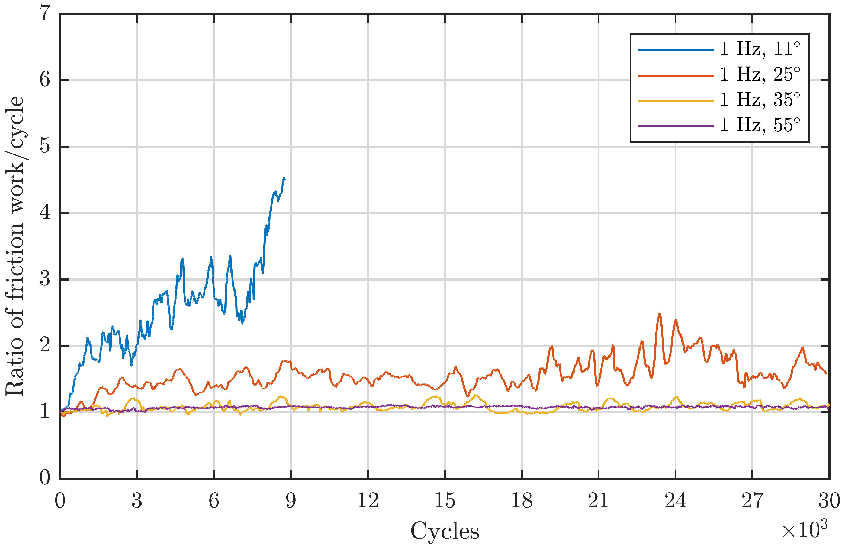
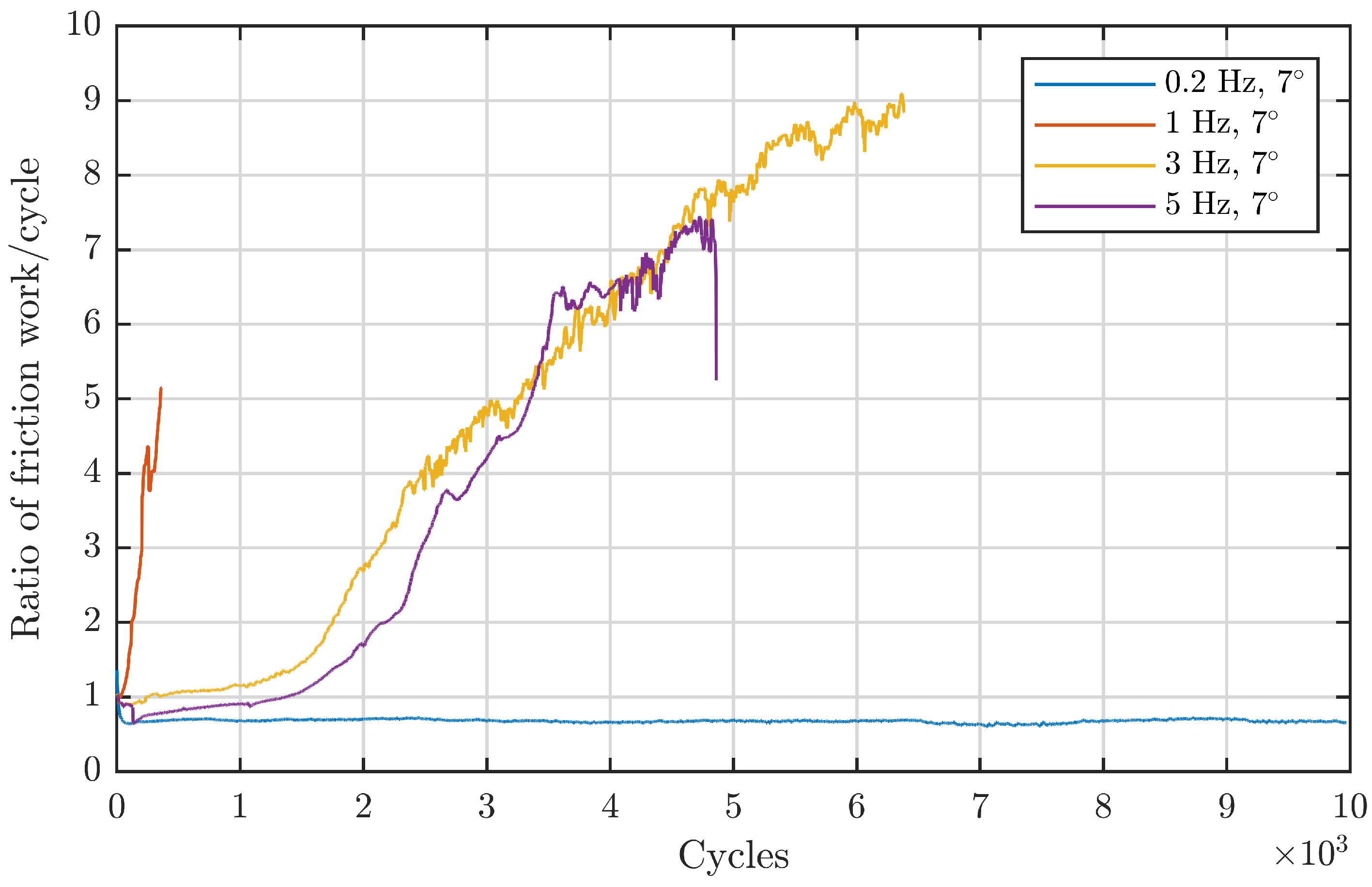
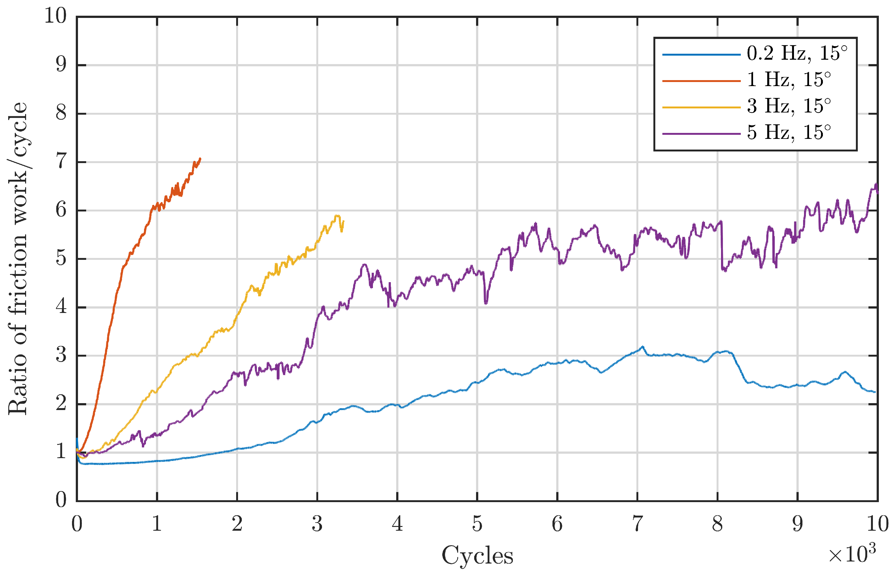
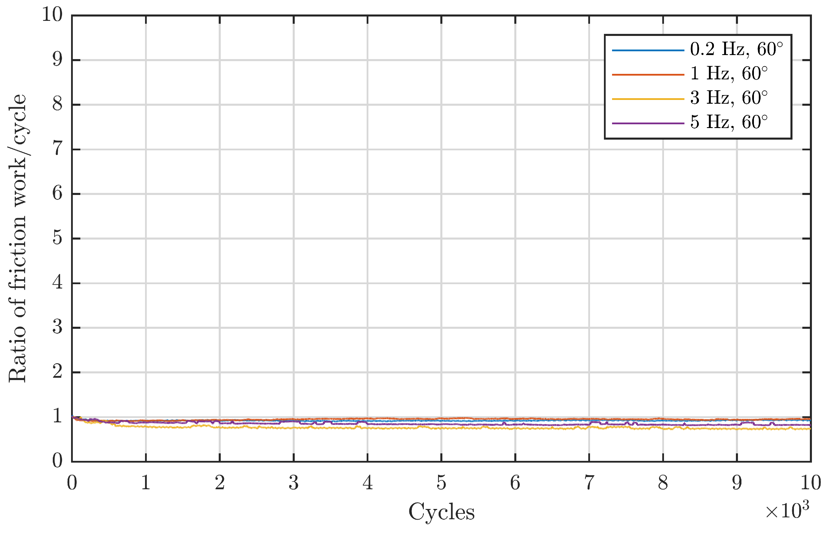
Assessing the response of the energy ratios from the 81212 bearings to an increasing angle can be performed by looking at
Figure 7 and
Figure 8. Both confirm the observed regimes of Wandel et al.
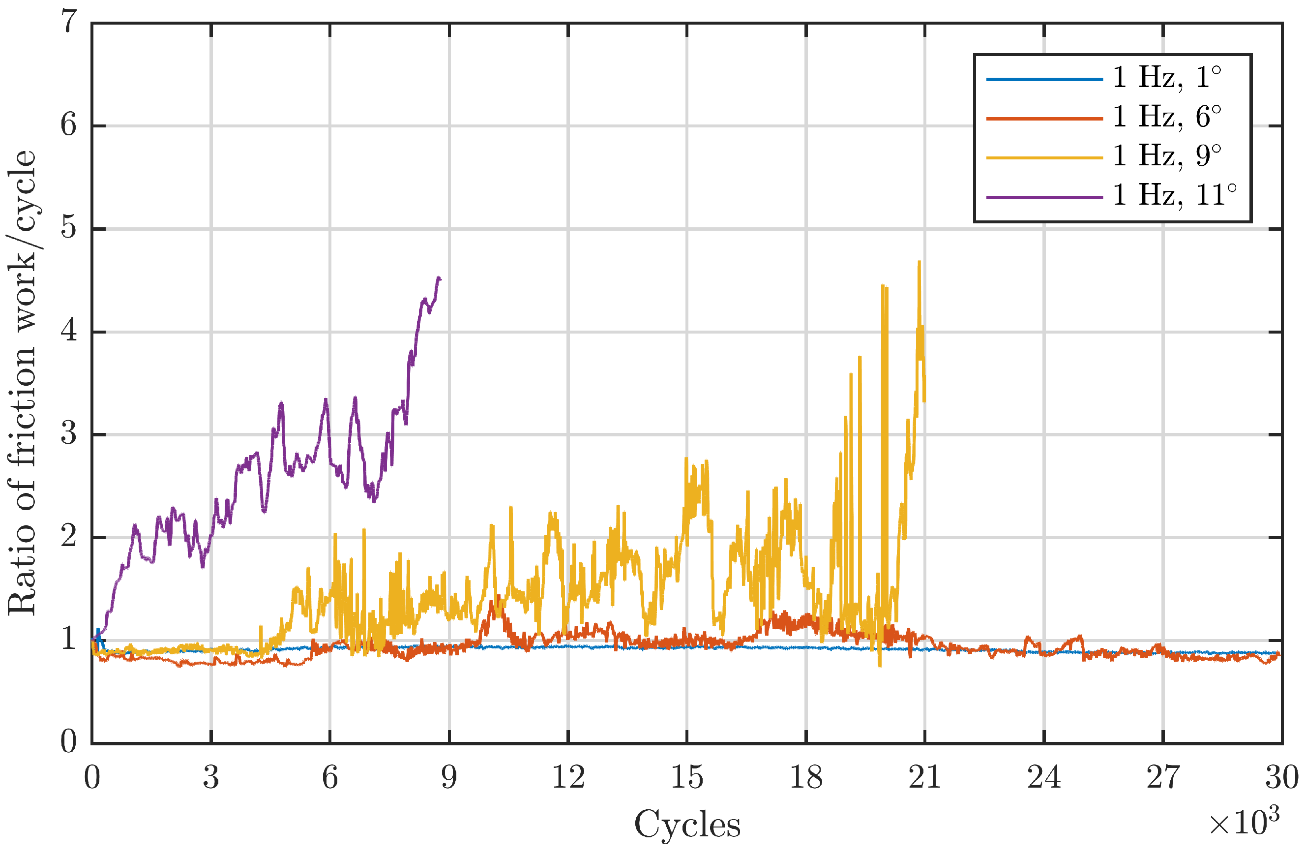
Figure 7 comprises angles that are located in the first regime: an increase in angle at a constant frequency leads to more severe damage.
Figure 8 depicts the second and third regime: increasing the double amplitude from
onwards while keeping the frequency constant at 1 Hz leads to continuously lower energy ratios. From this standpoint, the observed double amplitude behaviour from Wandel et al. also seems to be valid for line contacts in the same dimension. To validate this also for the larger-sized, downscaled blade bearings, a less direct approach is necessary since there is no directly comparable data with a constant frequency due to the different underlying design of the experiments. Since for these experiments the maximum entrainment velocity was kept constant, an increasing
ratio results in a decreasing oscillation frequency. This hinders a direct comparison between the frequency-angle-based and the velocity-angle-based testing approach. Therefore, in the following, the starvation number from Equation (
1) is converted into a velocity-based formulation. For a given double amplitude
and a frequency
f, the maximum (max) inner ring (i) angular velocity in an absolute coordinate system for a sinusoidal motion of the inner ring is:
For a bearing with a fixed outer ring in an absolute coordinate system, the inner ring angular velocity in a cage-fixed relative system can be expressed as [
31]:
The factor
describes the ratio between the rolling element radius
R projected into the plane perpendicular to the bearing main axis and the pitch diameter
of the bearing. For a given contact angle
it is:
. The maximum entrainment speed under the observed conditions
can therefore be expressed as:
To insert Equation (
6) into the starvation number, it is desirable to substitute the double amplitude by the
ratio. By integrating the absolute value of Equation (
6) over half a period, one can obtain the following relation between
x and the double amplitude
:
Therefore, the product
can be put into a form dependent only on
and
:
. Hence, the starvation number can be transformed into a version depending on the maximum entrainment speed:
According to Equation (
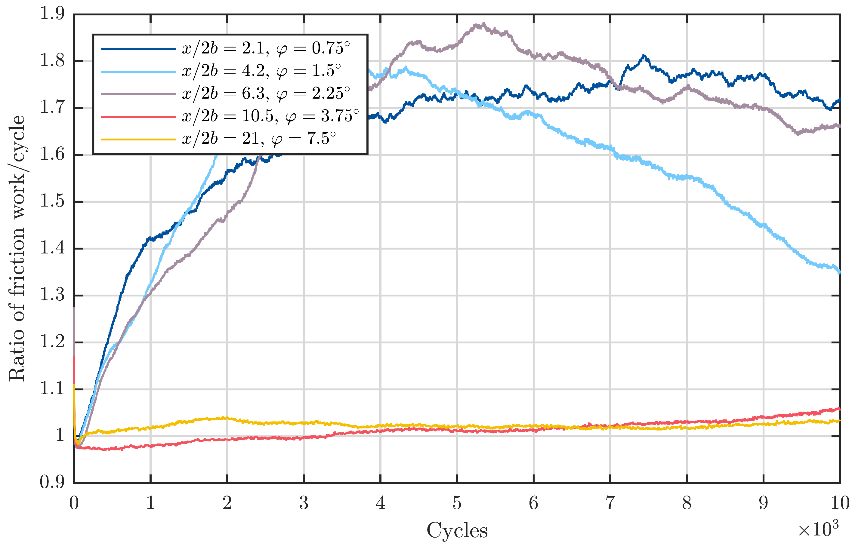
8), a constant maximum entrainment velocity, such as in the downscaled blade bearing experiments, corresponds to a constant risk of the contact running dry and therefore also damage initiation in the first regime. In this form,
Figure 10,
Figure 11 and
Figure 12 are more clear with regard to the angle behaviour described by the oscillating grease starvation theory by Wandel et al. Starting with
in
Figure 10, the graphs for the first three double amplitudes
,
, and
are nearly the same. This complies with the starvation number for a constant entrainment velocity (Equation (
8)) and indicates that these three double amplitudes/
ratios lie within the first regime. For the two remaining amplitudes of
and
in
Figure 10, the friction energy ratio stays as one throughout the course of the experiment, although the entrainment speed remains constant. This can be explained by the second or third regime of the starvation number, which is numerically represented by lower values or zeros in these regimes. Physically spoken, these values greater than
are believed to correspond to an immersion of the rolling element into grease reservoirs present close to the pockets of the cage. Hence, there is the possibility of grease and base oil being dragged into the contact and thus preventing damage initiation.
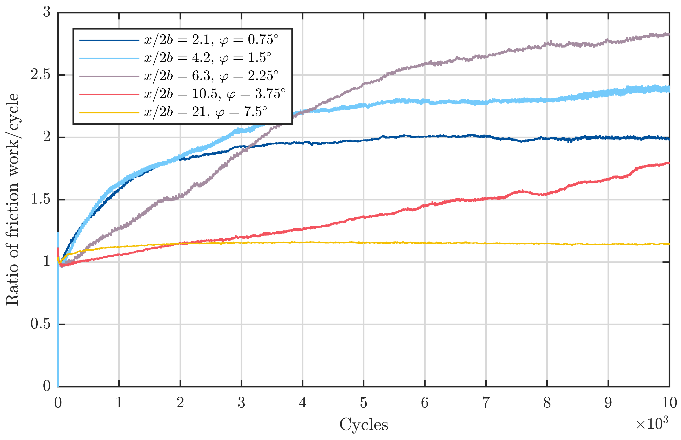
Looking at the greater entrainment velocity of
in
Figure 11, generally higher values of the energy ratio are visible. This corresponds to a higher starvation number due the increased speed (see Equation (
8)). The previous observation of nearly identical energy ratio curves for low double amplitudes does also apply in this case. For the double amplitudes of
,
, and
, the curves of the energy ratio are similar. Therefore, these double amplitudes can be located in the first regime. The double amplitudes
and
exhibit lower levels and therefore belong in the second regime. For a speed of
, the double amplitude of
did not exhibit any friction energy rise. This can be explained by the rise in velocity and, therefore, also starvation risk by means of the starvation number in the second regime. Again for a double amplitude of
there is no rise in the torque signal, which supports that this amplitude is located in the third regime. For the highest entrainment velocity of
, the findings of
are generally confirmed. The only discrepancy is that the energy ratios in the first regime are a bit lower than for the previously discussed speed of
. It should be mentioned that the starvation number is primarily intended to predict the general occurrence of starvation and therefore also rise in friction energy. However, the magnitude of the friction energy over the cycles is also dependent on the wear development involving possibly more factors. However, the starvation theory presented by Wandel et al. showed good performance in explaining the results of the SBB and 81212 with respect to the influence of the double amplitude
. A direct comparison with further literature is difficult since there are no other known studies incorporating torque measurements in combination with a systematic variation of the double amplitude. Phaner-Goutorbe et al. could not find a direct difference in the wear progression with double amplitudes ranging from
to
[
12]. Their judgement was based on surface changes only under consideration of significantly higher frequencies of up to 20 Hz. A broader evaluation of the test is not available. Furthermore, a direct link between the change in surface roughness and friction torque is not reasonable, as can be seen by Wandel et al. [
32]. After the initiation of damage by a lack of lubricant, several wear mechanisms can occur in succession. If after a first adhesive phase, abrasion sets in, the surface roughness will even decrease again, even though a significant rise in friction torque occurred. For this reason also, the results of Maruyama et al. are not directly comparable to this investigation, although they show the same behaviour regarding the double amplitude in the first regime with their low-viscosity base oil grease [
13].
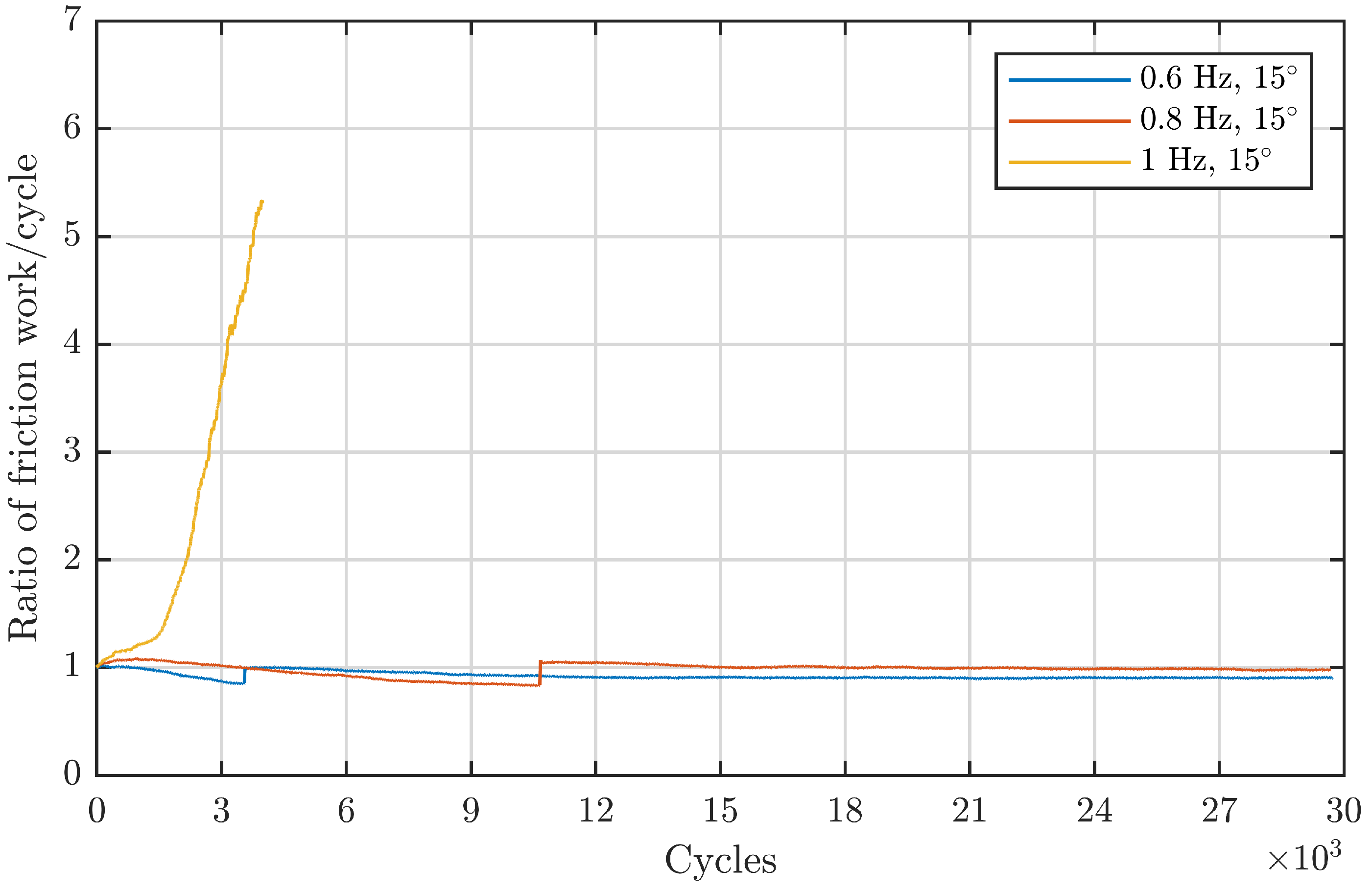
After the influence of the double amplitude, i.e., the
ratio, was discussed, the discussion of the frequency followed. Wandel et al. observed a continuous increase in damage development and torque rise if the frequency was increased for a constant double amplitude [
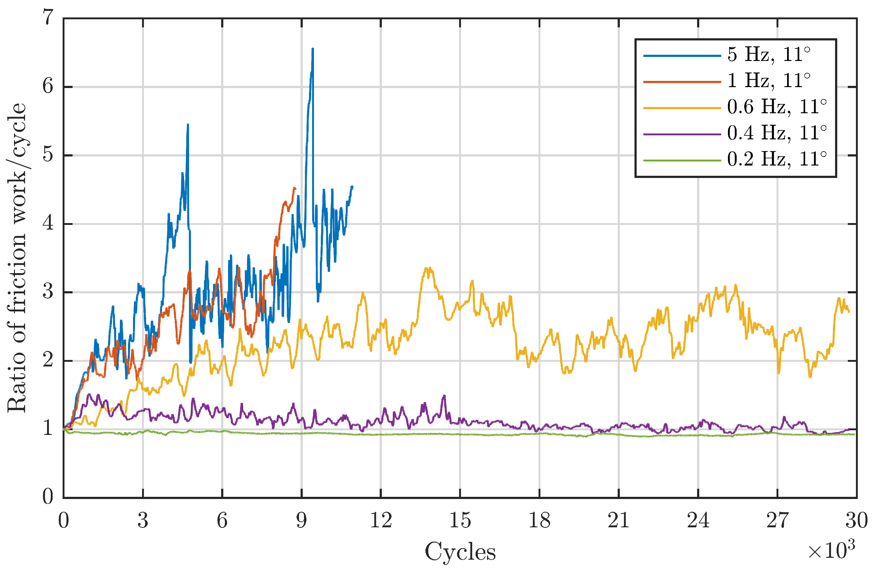
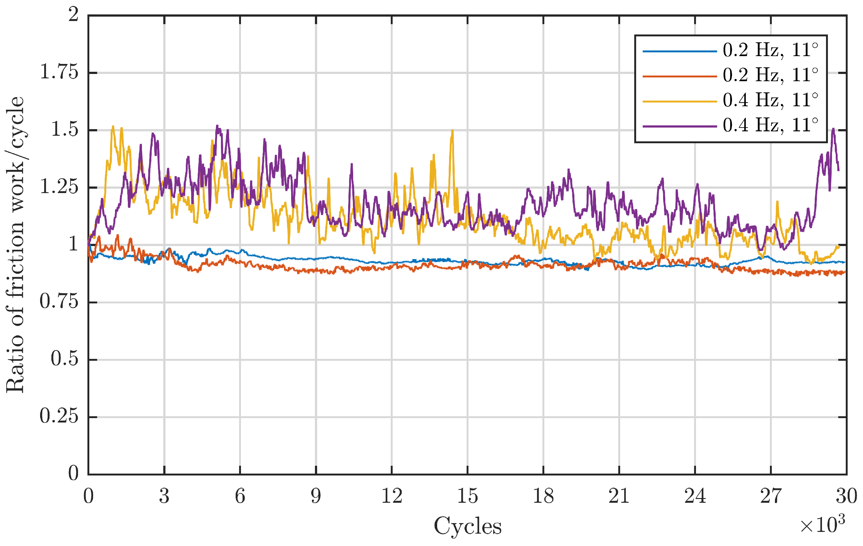
21,
25].
Figure 5 confirms this for the 81212 bearings. For a double amplitude of
, the critical frequency
that first leads to damage initiation seems to be between 0.2 and 0.4 Hz. For comparison between point and line contacts, the experiments of Wandel et al. with 7208 bearings have been complemented by the results in
Figure 9. In this case, the critical frequency lies between 0.8 and 1 Hz. The critical frequencies for the given
ratios are estimated by the mean value of the corresponding borders given in
Table 4. For the line contact of the 81212 bearing, the critical frequency is three times higher than for the point contact of the 7208 bearings. This finding is in good accordance with the starvation number by Wandel et al. since the longer contact length hinders a fast replenishment of the area around the rolling element. To evaluate the numerical accuracy of the starvation number, the same critical starvation number is assumed for both bearings. Since the same grease was used and both angles lay within the first regime, Equation (
1) yields:
This ratio of the critical frequencies calculated based on the contact geometry is 2.8 and therefore in good accordance with the experimentally determined ratio of 3. For this example, the starvation number of Wandel et al. seems to perform satisfactorily for line contacts. Before a more comprehensive analysis of the predictive capabilities of the number is performed, the frequency-sensitivity of the SBB is discussed.
To assess the influence of the frequency for the SBB, tests with the same double amplitude in
Figure 10,
Figure 11 and
Figure 12 are compared. Since the entrainment speed is increasing for each of these figures and fixed double amplitudes are compared, the frequency is increasing for the following way of comparing. Starting with a double amplitude of
, it can be observed that the increase in frequency by changing the entrainment speed from
to
leads to an increase in the energy ratio maximum from 1.8 to 2.8. This increase is in agreement with the observations from the smaller 7208 and 81212 bearings. Contradicting this, a further increase in the speed to
brings a lower maximum of 2. The remaining double amplitudes in the first regime,
and
, show a similar trend. As mentioned, the starvation number is mainly intended to assess the general occurrence of wear and not so much the wear progress. This indicates that there might be a speed-dependant influence in the wear progression. At a double amplitude of
that is suspected to lay in the second regime, the maximum value of the energy ratio increases slightly when increasing the speed from
to
. For a double amplitude of
there is no difference between the discussed speeds since the double amplitude lays within the third regime where damage does not arise any more. Again, a comparison to Phaner-Goutorbe et al. and Maruyama et al. is not possible since torque values were not measured in their investigations [
12,
13].
In summary, the presented results for the investigated bearing types agree with the results by Wandel et al. regarding the wear initiation in dependency of the double amplitude and oscillation frequency [
21,
25]. They summarised their work in “colourmaps” that show the frequency on the abscissa, the double amplitude on the ordinate, and represented torque using a colour scale.
Figure 15 uses the same concept to summarise the results for the SBB (a) and the 81212 bearings (b), but instead of using the maximum torque, the average energy ratio of the test is used. In further contrast to the maps of Wandel et al., not the whole grid shown in the maps was covered by experiments. Hence, the data for the maps were obtained by linear regression for a constant double amplitude and subsequent linear interpolation between this regression data for a constant frequency. For the 81212 bearings, additional experiments were completed near the critical starvation number to have a larger amount of data. The parameters of the additional experiments are given in
Table A1. For the SBB, the lines of constant speed are indicated as well. The maps confirm the previous discussion of the results and show the different regimes of the double amplitude and the frequency influence.
For a more quantitative analysis, the starvation numbers
for the SBB, the 81212 bearings and the additionally tested 7312 bearings were calculated. To determine the
x-thresholds of the second and third regime, the highest and the lowest value of the regimes identified by the energy ratio were used (details in
Table A2). In
Figure 16, the mean value of the energy ratio for each test is plotted over the calculated starvation numbers (1 was added to the SN to enable logarithmic scaling). For reference, the 7208 tests of Wandel et al. with the same grease as used here are also included. Although there is some scatter in the data, it is noticeable that most of the experiments with low energy ratios also show low starvation numbers and vice versa. By defining a critical energy ratio of
, i.e., to tolerate a maximum increase in friction energy by 40%, and assuming a critical starvation number of
, a classification error of 22% is obtained.
Table 5 shows the corresponding data. In
Figure 17 this critical starvation number is used to classify all the experiments and show the results again in the form of a boxplot. Although there are some outliers for SN-values below the critical limit that show an energy ratio in the magnitude of two, the general performance is satisfying especially when fluctuations typical of grease-lubrication are considered. It shows that the oscillating grease starvation number proposed by Wandel et al. [
21,
25] based on experiments with only one small-scale bearing type and different greases also seems to be a valid tool to detect possible wear in critical operation conditions also for different contact geometries and larger bearings.
A closer look at Equation (
8) reveals that the SN number is a kind of capillary number, as it is often used to characterise flows dominated by surface tension. Although there is a variety of these numbers, a basic form that puts the viscous forces into relation to the surface tension
reads:
[
33]. The viscous forces are represented by the product of dynamic viscosity
and speed
v responsible for the shear in the fluid. The Ca number can be used to formulate the starvation number in the following form:
where
is the elliptical ratio of the contact. This formulation is subject to the assumption that the entrainment velocity
takes the role of the velocity
v responsible for the viscous shear in the Ca-number. The comparison with the literature shows that capillary effects play a role in the lubrication of contacts by driving the supply of the inlet meniscus [
34]. Recent publications employing VOF-methods show also a strong dependency of distinctive meniscus features on the Ca-number [
35,
36]. Chen et al. explain the dependency on the capillary number by the force balance between capillary and viscous forces at the leading edge of the meniscus based on numerical investigations [
35]. Although such effects can play a role in this case under oscillating conditions and probably boundary or mixed friction, this explanation is not strictly compatible with the ideas of Wandel et al. [
25]. They used the viscosity in their formulation of the starvation number to express the resistance of base oil against replenishment of the area around the contact. Therefore, the shear of the oil during replenishment is not caused by the entertainment speed, and its use as the shear speed is not entirely in line with Wandel’s theory. Nevertheless, such mechanisms concerning the meniscus around the contact could occur in connection with Wandel et al.’s theory. Several studies have already implemented the non-newtonian flow behaviour of grease into VOF-algorithms to study grease flow in ball bearings or other machine elements and brought interesting insight into the distribution of grease in these systems [
37,
38,
39,
40]. Nevertheless, the role of the bleeding of the base oil remains unclear in these models. A comprehensive numerical method that models all of the relevant effects, including three-phase flow around the contact, mixed lubrication conditions, and the onset of wear has not been implemented in the literature due to the complicated nature of multiphysics modelling [
1].
Thus far, the theory of Wandel et al. [
21,
25] and the explanations in this paper focus solely on the base oil flow and interpret the thickener as a base oil reservoir next to the track. Cann showed that grease thickener forms a lubricating layer at rolling speeds comparable to the speeds in this investigation [
41]. Although the contact pressures in this investigation are higher compared to Cann, it is desirable to analyse the role of this thickener layer for the current application. Furthermore, the starvation number is not yet validated regarding the influence of the surface tension
between the base oil and air. In addition, differences regarding the wettability of the base oil on the raceways and the cage are not incorporated into the starvation number. From the standpoint of established theory, wettability will influence base oil replenishment and therefore also wear initiation [
42]. These effects can become relevant when applying the starvation number to hybrid or all-ceramic rolling element bearings. Basically, the general concept is transferable to different bearing materials since the underlying principle of displacement and replenishment is also applicable to changed materials. As mentioned, care needs to be taken regarding the critical value of the starvation number since different wettability can have an influence on the replenishment. Furthermore, the development of the torque ratio in the case of damage can change due to altered wear mechanisms of ceramic components [
43].
As all results regarding the starvation number are based on experiments with constant operating conditions; it is questionable how it can be applied in applications with dynamically changing operating conditions, such as wind turbine applications. Hence, the influence of non-constant operating parameters needs to be further investigated. In contrast to the static loading and constant oscillation parameters of the herein-discussed experiments, blade bearings are subjected to varying loads that can lead to a change in contact angle and therefore also a change in the stressed contact area. Furthermore, the effect of alternating oscillation parameters above and below the critical starvation threshold, in addition to the changing loads, are not yet foreseeable.


