1. Introduction
The piston pin is an important component of the combustion engine’s assembly of the crankshaft, pistons and connecting rods [
1,
2], and the function of the piston pin is to ensure a hinge joint between the connecting rod small end and the piston. The piston pin transfers the forces exerted by combustion gases onto the piston in the engine combustion chamber, as well as the inertia forces in the assembly of the crankshaft, pistons and connecting rods. It should be noted, therefore, that the piston pin operates in severe conditions, which consist of high operation temperature, high combustion pressure [
3,
4] and high loads with a periodically variable nature. These conditions result from the operation phases of the assembly of the crankshaft, pistons and connecting rods, and from limited lubrication. The authors of [
5] used thin layer sensors to measure the distribution of oil film pressure on the contact surface between the piston pin and the hole in the small end of the connecting rod to determine the distribution of stresses on the petrol engine piston pin in real operation. Tests were conducted for various values of the displacement amplitude within the range up to the pin operation temperature in the order of 620 °C. Owing to such a device, researchers demonstrated that oil inflow was insufficient immediately after the engine was started. They also showed that high pressure in the order of 100 MPa and higher occurred in places at the contact surface surveyed. The basic group of destruction factors include pin-operating conditions in the engine piston zone, that is, high temperature, variable humidity, impurities and the lack of lubrication continuity. The authors of [
6] examined the influence of a lubricating medium on fretting wear of the surfaces of elements made of CuNiAl and 42CrMo4 in the flat-on-flat contact. The authors demonstrated that the wear mechanism depended on the lubricating medium.
Piston pin deflection caused by the forces acting on the connecting rod [
7] is an additional state of the piston pin operation, resulting from the structure of the joint between the piston and connecting rod. The authors of the aforementioned work investigated the states of destruction of piston pins mounted in piston bosses by means of the hinge joint and in the small end of the connecting rod by means of the thermocompression bond. Thus, a rotational bending moment comes into being, which, in combination with microvibrations, contributes to the rise of additional damage or wear, and, in the case of insufficient lubrication, even to scuffing. Scuffing has so far not been fully recognized due to a large number of factors causing that wear. The occurrence of that type of wear would lead to catastrophic consequences causing the damage of the entire assembly [
8]. Other factors contributing to wear may be the processes accompanying the technological processing of the piston pin. During treatment, residual stresses come into being at the section of the piston pin being reworked as a result of thermoplastic deformations and phase changes in the cemented layer of the piston pin outer surface [
9,
10], which may also adversely affect the subsequent operation of piston pins.
The authors of [
11] described an example of the wear of the piston pin, which broke during operation. The accumulated service mileage was as low as approximately 750 km. Transverse and longitudinal cracks occurred on the damaged piston pin, and these had been initiated by the fatigue of the material. The cracks originated at the inner hole surface and ran towards the outer piston pin circle. Strong decarburization occurred at the inner hole surface. The damaged piston pin was made of 20Cr steel, and the inner hole and outer circular surfaces of the piston pin were designated for carburizing.
Given the operating conditions described above, modern engines are equipped with piston pins which are distinguished by high rigidity, resistance to fatigue wear, as well as to wear and tear. For that purpose, good quality carbon steel, or carburizing alloy steel, is used as the structural material. In the case of engines with a charging system, however, nitriding carbon steel is used.
In connection with the need to limit the weight of the components of the assembly of a crankshaft, pistons and connecting rods moving in the reciprocating motion, and in order to achieve balanced conditions, attempts to reduce the piston pin weight are being made. Hence, piston pins take the shape of a thick-wall tube with the diameter and wall thickness complying with the standards. Such tubes are manufactured by hollowing in compliance with dimensioning principles, i.e., pin length equals 0.8–0.9 of the piston diameter, and the outer diameter equals 0.3–0.4 of the piston diameter. Such a dimension ratio enables the unit pressures on the piston boss to be minimized. In addition to appropriate weight and dimensions, piston pins should be distinguished by low surface roughness parameters, which enables the reduction of the susceptibility of the mating components to wear [
12].
One of the methods of assembly of the piston pin in the connecting rod small end is a thermocompression bond, which is used in spark-ignition engines. The hinge joint in piston bosses does not require the use of protection devices with thrust (Seeger) rings. The thermocompression bond requires, however, that the precise range of temperatures of the components being connected must be maintained: heating the connecting rod small end to 550 K and maintaining an ambient temperature for the connecting rod.
That bond enables the transfer of relatively high radial and axial loads, as well as static and dynamic rotational moments. Pin thermocompression bonds, however, cause the disadvantageous concentration of stresses, which coincides with cyclical rotational bending. At the same time, bending stresses occur, which coincide with compressive loads over the thermocompression bond length, making the pin more susceptible to damage and wear.
Growing combustion pressure, low viscosity oils, smaller oil supply and increasing stresses caused by the reduction of combustion engine dimensions lead to higher stresses in the bearing. As the mechanical and tribological loads on the piston pin bearings have direct influence on the life and operation of the entire engine assembly, it is necessary to develop a solid attitude to the design of the tribological assembly of the crankshaft, pistons and connecting rods [
13].
Severe piston pin operating conditions and the related possible premature damage, as well as the drive to reduce the vehicle weight, are an incentive to seek alternative structural solutions. The authors of [
14] investigated the option to use lightweight ultra-high carbon (UHC) steel with aluminum alloy from the point of view of steel performance during molding. Investigation results demonstrated that steel had high adhesion in high temperatures, and this disturbed the molding process. The ideal grain flow orientation was also determined, which contributes to the improvement of the dynamic strength of the piston pins.
The authors of [
15] postulated a numerical model, which fully represents the operating conditions of the friction pair of the piston bearing/piston pin/connecting rod small end, in order to investigate the tribodynamic relationships between them. The model was built on the basis of the principle of combining mixed lubrication models based on Reynold’s theory for friction pairs with Lagrange’s polyadic motion equations for the piston/connecting rod/crankshaft mechanism. The authors of [
16] developed a mathematical model for the reconstruction of the destruction of the assembly of the crankshaft, pistons and connecting rods of the engine during a hydraulic lock. In contradistinction to the existing models, this model makes it possible to consider not only connecting rod’s static deformation, but also enables the comprehensive assessment of the deformation of the connecting rod, piston pin and piston given the various volumes of the hydrolocking liquid.
It follows from the review of the literature that direct comprehensive research into piston pin wear has not been conducted.
The issue related to the lack of research related to the evaluation of the technical condition of piston pins or a negligible volume of such research was also noticed by the authors of [
17], who described the bench, designed by themselves, for the evaluation of the effects of the various surface engineering methods on the tribological performance of piston pins. To date, not much has changed in this regard, so the purpose of this study is to assess the technical condition of the piston pin of a spark-ignition internal combustion engine of a delivery vehicle operating under varying road conditions.
2. Materials and Methods
In order to determine the wear of piston pins that can occur during the daily vehicle operation, the developed test program was divided into two stages. First, the vehicle operation process was recorded from the brand-new condition to the symptoms of operational wear of the engines. Then, the components of the engine’s assembly of the crankshaft, pistons and connecting rods were disassembled, and the piston pins were removed from the engines with special care to prevent unexpected damage that could distort the images of damage and wear formed during operation. This process was followed by laboratory tests which included macro and micrographic observations and a surface roughness measurement.
2.1. Research Object
The object of tests presented in this article were engine piston pins fitted in the connecting rod small end by thermocompression bond, which were removed from two spark-ignition internal combustion engines of the same type and year of manufacture. The engines showed no recorded fault codes during EOBD II tests performed with a BOSCH KTS570 tester (Bangalore, India).
The engine oil used in the tested engines complied with the manufacturer’s requirements, i.e., 5W-40 according to the Society of Automotive Engineers’ (SAE) engine oil viscosity classification, and SN class according to the American Petroleum Institute’s (API) engine oil quality classification.
The Engine Control Unit (ECU) of these engines provided the start and stop function, which resulted in frequent engine starts under vehicle traction conditions. The starting dose of fuel with the participation of biocomponents causes the penetration of the unburnt part of the atomized fuel into the engine crankcase, and thus, into the oil pan, causing destructive secondary reactions with engine oil.
The piston pins of the tested engines were made of 20MnCr5 (20HG) alloy steel subjected to cementing to a depth of 0.7–1.0 mm and quenched to 63 HRC.
The tests of piston pins were conducted for all eight pistons of the assembly of the crankshaft, pistons and connecting rods. This study presents the results of testing those pins for which the heaviest wear was recorded.
The research program comprised two delivery vehicles that were used in a courier company service.
Table 1 presents the number of tested samples and the number of kilometers traveled by vehicles as part of operational tests.
During operation, the engines did not show any failure status and no error code was recorded.
2.2. Operational Test Conditions
The vehicles were operated on various routes and roads and served both urban and rural areas. At most routes, the terrain conditions were difficult and comprised mountainous areas with road inclination of 10% or more. This situation forced the drivers to drive in low gear and at a high engine speed frequently. At that time, in the assembly of the crankshaft, pistons and connecting rods, there occurred maximum thermal and mechanical loads which must be transferred by the piston pins. In addition, the vehicles were operated in various weather and air dustiness conditions. It should also be emphasized that the drivers of the monitored vehicles are professional drivers who had taken courses at driving skill improvement schools. Therefore, it should be held that those drivers drove the vehicles in accordance with the best practices for motor vehicle driving, without exposing the engine to accidental damage.
The monitored vehicles delivered courier parcels of various weights to private recipients and companies.
The histogram of the vehicle loaded with goods is presented in
Table 2. Each vehicle traveled a comparable route with a mileage of approximately 120,000 km.
2.3. Laboratory Tests
After disassembling the piston pins, macroscopic observations of their surfaces were conducted. The macroscopic evaluation of the surfaces was documented with a NIKON COOLPIX P900 camera (Melville, NY, USA) with a maximum magnification of 83×.
The macroscopic observations made it possible to determine the size and range of wear traces, as well as their location.
The damage areas were subjected to microscopic observation with the use of a JEOL JSM-5510LV scanning electron microscope (Tokyo, Japan), which is part of the equipment in the Department of Materials Engineering at the Faculty of Materials Engineering and Physics of the Cracow University of Technology.
The investigations by means of scanning electron microscopy were performed in the backscattered electron composition (BEC), backscattered electron shadow (BES) and secondary electron image (SEI) modes with the electron beam acceleration voltage equal to 20 kV.
The quantitative and qualitative microanalysis of the chemical composition of wear products on the damaged surfaces of the piston pin was carried out using an electron microscope equipped with an EDS INCA x-act Energy 350 spectrometer (England, UK).
Spectral analyses were performed in order to determine the chemical composition of the deposits in the area of the shrinkage connection between the piston pin and the connecting rod head. The results of the research determined the influence of biofuels, penetrating into the lubricating oil, on the process of the destruction of the shrinkage joint.
An analysis of the XRF and IR spectra in the infrared of the soluble part of the deposits on the piston pin in the destruction zone of the shrinkage connection with the connecting rod head was performed in order to identify the precipitated non-oxidized organic components. X-ray fluorescence spectra, including XRF ED energy dispersion, were recorded with an Oxford Instruments ED 2000 (England, UK) and infrared (FTIR) spectra were recorded with an FTS 175 BIO-RAD (Hercules, CA, USA).
Currently, there is a lack of information on the subject of research in this field, the results of which are of direct importance for the technology of engine production and their operation.
The microscopic observations made it possible to evaluate the wear products present in the tribological kinematic pair and determine the chemical composition and origin of those wear products.
The surface topography of the piston pins in the wear zones was examined by means of the Taylor Hobson’s Form Talysurf Intra device (Leicester, UK). The obtained data were used for the determination of roughness parameters and for their graphic presentation with the use of TalyMap Platinum 5.1 software (San Francisco, CA, USA).
3. Assembly Stresses in the Thermocompression Bond
Fitting the piston pin to the connecting rod small end through the use of a thermocompression bond requires high precision machining of the contact surfaces with low roughness and accurate coaxiality of the components. The limit heating temperature of the connecting rod small end must be strictly observed, which is achieved in the factory engine assembly process through the use of induction heating. An attempt to assemble the components at a reduced temperature of the connecting rod small end leads to surface seizing and to piston deformation due to excess pressure on the side wall. It is unacceptable to operate an engine even for a short time with an unserviceable cooling system as this may contribute to an excessive increase of the joint temperature and, consequently, to piston pin displacement, cylinder surface damage and piston boss breakage.
Manufacturers opt for this method of pin position determination as the method does not require the use of any additional elements, such as expanding rings and necessary necks, which are the notch zone. The resulting thermocompression bond shows high resistance to variable and impact loads.
The calculation of the diameters of the thermocompression bond is conducted on the assumption that there is a stabilized homogeneous temperature field after the bond has returned to ambient temperature. Therefore, it is necessary to determine pin and connecting rod small end diameters so as not to introduce excess stress field gradients. Then, a state of quasi-stabilized temperature equalization between the components being joined together will occur at a higher level than the temperature in the piston pin zone during engine operation. A fundamental error is the introduction of the assumption that the equivalent stress value is close to the yield point of the material. Reaching the yield point of the surface layer of the pin or the connecting rod head may cause a disconnection of the shrink connection in this zone, then a displacement of the pin and destruction of the cylinder, and finally the cracking of the piston and complete destruction of the engine. In addition, it is necessary to take into account the effect of gas forces in the combustion chamber and inertia forces depending on the spatial configuration of the cylinders and on the dynamics of the assembly of the crankshaft, pistons and connecting rods.
The calculations, which are a verification of the thermocompression bond used by the manufacturer of the internal combustion engine model under consideration, are based on the theory, which is a development of the Lame problem, permitting the determination of stresses on the contact surface of the elements joined together
Equivalent stresses reduced according to the Huber–Mises–Hencky hypothesis were calculated for the outer surface of the pin in the thermocompression bond zone, with the assumed actual geometric values of the components (
Figure 1) and the use of Formula (1).
Inside diameter of the piston pin: .
The thickness of the connecting rod forging in the piston pin zone: .
Outer diameter of the piston pin: .
Value of the tolerance of the elements: .
Connecting rod temperature: .
Coefficient of dry friction: .
Fit: permanent roller: S7h6.
Radial shrinkage stresses after cooling the connecting rod head
where:
, —Poisson’s ratio, —Young’s modulus of the piston pin, —Young’s modulus of the connecting rod.
, , , .
,
.
Reduced stresses determined according to the Huber–Mises–Hencky hypothesis
where:
—radial stresses in accordance with the Lame theory.
—circumferential stresses.
—circumferential stresses.
, , , .
According to the above calculations, the value of the equivalent reduced stress for the assumed assembly conditions of the joint and its operating conditions is 194.6 MPa.
The actual geometrical values of the elements and the complex stress state resulting from surface pressures on the pin surface as a result of thermal (shrinkage) connection, gas forces and inertia forces were adopted for the calculations.
The maximum force of inertia for the rated revolution speed is Fbp = 6.3 kN. During the analysis of the developed indicator diagram of the engine being tested, of the pattern of the resultant gas force and of the force of inertia of the elements moving in reciprocating motion, the resultant value of force Fw = 12.5 kN acting axially on the piston was determined. Outside the TDC (top dead center) piston position, the component of the force acting along the axis of the connecting rod reaches the maximum value of 10.6 kN. In relation to the contact surface between the connecting rod small end and the piston pin, this force induces an additional stress of = 39.3 MPa. The zonal stresses do not exceed 240 MPa, which indicates the correct selection of the operating conditions for these components in the engine under consideration. According to the engine manufacturer’s recommendations, the limit stress values for piston pins made of 20MnCr5 (20HG) alloy steel, cemented to a depth of 0.7–1.0 mm and hardened to a hardness of 63 HRC should be 270 MPa.
4. Test Results and the Discussion
4.1. Macroscopic Observations of the Piston Pin Surface
After the piston pins were disassembled, their surface was viewed. A sample result of these observations is presented in
Figure 2. All the eight pins had similar wear traces. These were noted at both the thermocompression bond of the connecting rod and at the pin hinge joint in the piston.
Wear is present around the entire circumference of the piston pin in randomly spaced locations. The wear traces have irregular shapes of varying sizes. The zone of pin interaction with the connecting rod is distinguished by a larger area of top layer destruction, especially in the central part, compared to the other surfaces. It is there that there are many more individual wear traces with the area of more than 6 mm2, and they are clustered close together.
Wear traces in the piston boss zone are brown, which indicates oxidation of the damaged area. The formation of oxides is probably related to the occurrence of excessive clearance between the mating components, which is caused by operational wear and by piston pin deflection, thus allowing the damaged areas to come into contact with oxygen.
The noted damage on the pin surfaces mating with the piston bosses is typical of scuffing, which developed as a result of insufficient lubrication of the mating components or oil film breaking. To confirm this proposition, microscopic observations were conducted, the results of which are presented in the following subsections.
4.2. Analysis of Deposits on the Top Layer of the Piston Pins under Investigation in the Lateral Zones of the Thermocompression Bond
A disturbing phenomenon was noted, which is the loss of the contact surface between the pin and connecting rod small end in the outer zones of the thermocompression bond, along with the penetration of sintered engine oil fractions. The penetrating carbon deposits contain biofuel additive components, which exacerbate the destruction of the thermocompression bond due to accelerated corrosion processes on low-alloy steel. As a result of these observations, the microscope photos (200× magnification, reflected light) of the deposits on the piston pins in the destruction zone of the thermocompression bond with the connecting rod small end were analyzed.
Figure 3 shows the wear processes of the side zones of the pin on the outer edges of the connecting rod head together with the phenomenon of chemical corrosion, resulting from the ingress of an excess dose of atomized fuel containing biocomponents into the engine crankcase, and then into the engine oil pan.
The penetration of carbon deposits was noted in a zone about 1.5 mm wide on either side of the thermocompression bond. The penetration of the carbon deposit indicates the progressive destruction of the thermocompression bond and the chemical interaction of fuel-diluted oil with biofuel components entering the engine inner zone, mainly during the start-up phase.
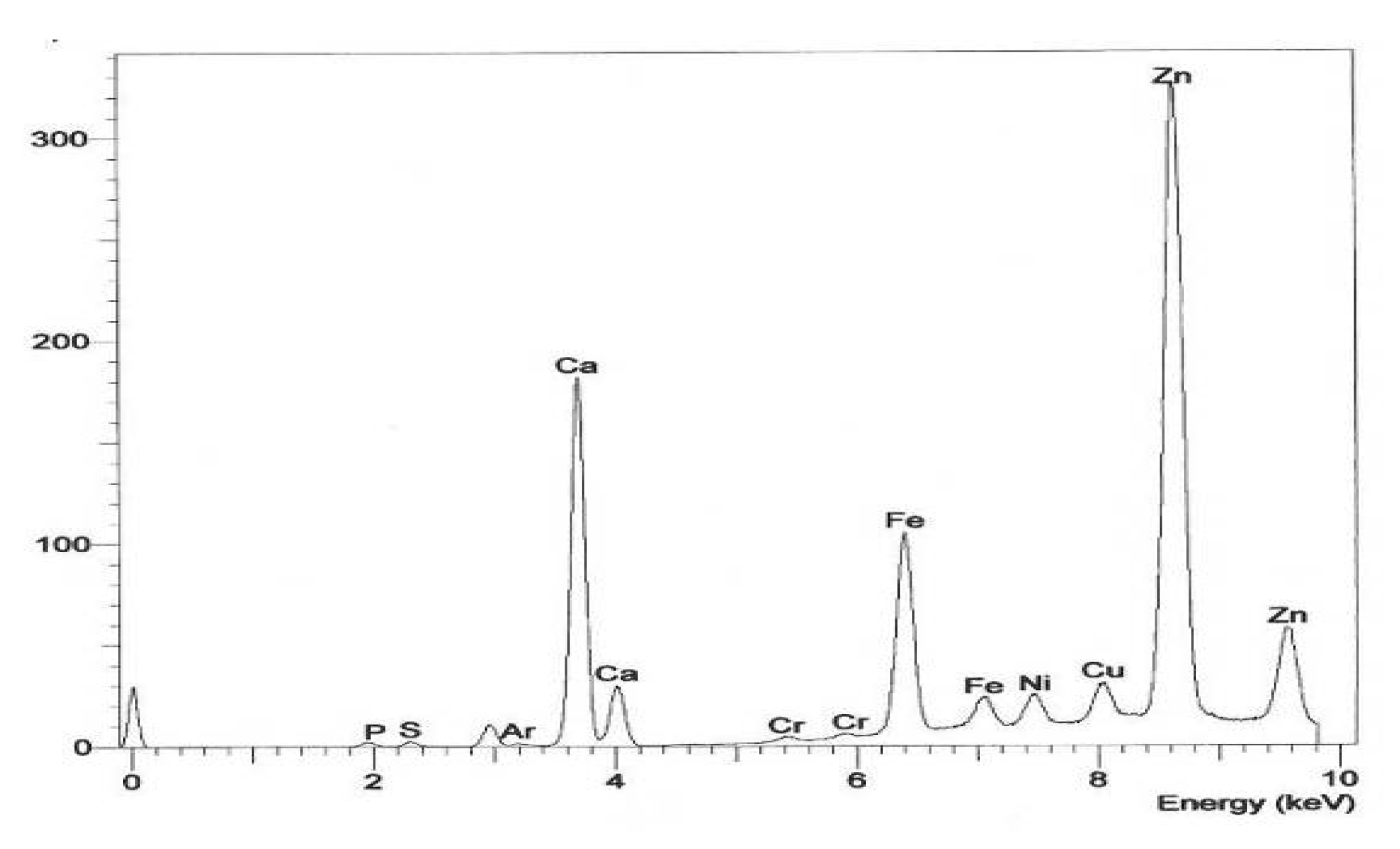
An XRF and IR spectra analysis was also conducted on the soluble part of the deposits on the piston pin in the destruction zone of the thermocompression bond with the connecting rod small end (
Figure 4 and
Figure 5).
Spectral analyses were targeted at the identification of the chemical composition of the deposits, which were used to determine the influence of the use of biofuel on deposit formation. The application process comprised the evaluation of the contents of precipitated non-oxidized organic components. X-ray fluorescence spectra, including XRF ED energy dispersion, were recorded with an ED 2000 Oxford Instruments spectrometer, while infrared (FTIR) spectra with an FTS 175 BIO-RAD one. The spectrum at approximately 1655 cm−1 is the most intensive diagnostic area within the 2000 cm−1–1600 cm−1 range. This confirms the occurrence of the oxidation of organic compounds to carbonyl and carboxylic structures. The effect of these compounds on nitrogen oxides is most likely related to the presence of the hydrates of carboxylic acid salts. These substances may also originate from the oxidation and degradation of refining bases present in engine oil. The 1630 cm−1 band originates from other compounds containing C-O-NO2 bonds. These come from nitroxidation of engine oil and fuel components by nitrogen oxides. An intense band of 1747 cm−1 was noted, which is associated with the presence of esters; it cannot be clearly determined, however, whether these are non-degradable esters of biofuels, the products of their degradation, or di- or trimerization. The complex around 1720 cm−1 originates from other carbonyl or carboxyl compounds, while the band around 1633 cm−1 indicates the presence of products resulting from the interaction of nitrogen oxides with fuel oxidation products. The weak band around 1735 cm−1 originates from other compounds containing C=O bonds, which are formed as a result of the oxidation of diesel oil and of a fuel component.
4.3. Microscopic Observations of the Piston Pin Surface
The surfaces affected by wear were viewed on a scanning microscope. Sample results of these observations are presented in
Figure 6.
The microscopic images clearly confirmed the speculations made on the basis of the macroscopic observations that scuffing could develop on the piston pin surface, and such scuffing comprises abrasive and adhesive wear caused by the insufficient lubrication of the mating parts [
18,
19]. The effect of wear is an increase in temperature, friction and vibration in the assembly [
20]. The loss of both thermal and mechanical balance leads to catastrophic operational consequences [
21]. Extreme local jumps in surface temperature result in the adhesion of mating components, thus generating a high coefficient of friction [
22] and leading to adhesive wear [
23,
24].
The images show numerous local places of top layer damage. The predominant damage is the formation of material build-ups on the pin surface. As a result of vibrations occurring in the system, these build-ups undergo plastic deformation as well as cracking and displacement along the tribological kinematic pair. The source of origin of the wear products that generate the multiplication of material build-ups is the shorn microirregularities occurring on the surface of the mating components. These microirregularities come into being as a result of friction and adhesive wear. The insufficient lubrication of the piston pin surfaces and of the components mating with the pin creates suitable conditions for the initiation of the wear-related phenomena mentioned above. The mating surfaces are distinguished by low roughness parameters and this, under the operating conditions described above, leads to bonding the tops of the irregularities and then to their pulling out. Moving wear products, micromachining, as well as grooving, bring about scratches which may be the cause of microcracks and, these will, with the passage of time, contribute to the development of fatigue wear.
4.4. Measuring the Surface Profile of the Piston Pin
The wear of the elements of the tribological kinematic pair results in the changes of surface geometry and the top layer structure, which arise as a result of the mutual influence of the mating surfaces. The degree of wear depends, first of all, on the operation environment of that tribological kinematic pair. One of the ways of measuring the changes in surface geometry is the evaluation of the profile of the surfaces [
25]. The configuration of the surface structure, including the degree of surface isotropy, influences wear intensity [
26].
The piston pin surface profile in the part mating with the piston boss is shown in
Figure 7. The result of the 3D measurement of surface roughness is presented in
Figure 8.
Table 3 lists the measured parameters of the surface roughness of the non-worn pin and the values of the pin surface parameters in the place of wear marks in the side zones of the connecting rod head as a result of the progressive destruction of the material, which reduces the durability of the shrink joint.
During the analysis of the results of roughness measurements, an increase in the parameters on the surface affected by wear can be noted compared to the surface without wear traces. The increase in roughness parameters is the result of build-ups rising, among other places, on the surface, and originating from the abrasion of the tops of irregularities of the mating elements.
All the measured structures had a random nature, as evidenced by the vanishing autocorrelation function.
Greater surface roughness reduces wear-resistance, in particular, corrosion resistance, due to the increase of the actual contact surface area of the wearing elements. For this reason, the height surface roughness parameters and the radius of curvature of the pits have the greatest influence on wear intensity.
A change of the Sku kurtosis and Ssk skewness coefficients (from the positive value for the surface not affected by wear to the negative one for the affected surface) may be noted, which indicates a change in the surface from a plateau to a pointed shape. All surfaces have a random isotropic structure.
The density of the local summit tops with a tendency to diminish, the large fractal dimension and the increasing surface development all confirm the continuous tendency of the surface to develop scuffing.
The surface affected by wear has the smallest rate of fluid retention by the core compared to the unaffected surface.
Thus, it can be stated that the piston pin surface constantly maintains the conditions that ensure fluid retention between the mating parts. This is disadvantageous, since such retention is conducive to wear that can lead to the development of fatigue wear and, consequently, to the fracture of the component. Based on the noted changes of the parameter values, it may be stated that intensive removal of the highest summits of the profile takes place and the load-bearing ratio of the surface increases.
Growing parameters confirm the loss of the material as a result of the cyclical load impact and the continuous generation of wear products in the tribological kinematic pair. During engine operation, these products move over the entire joint length, thus causing surface scratches or the formation of micropits and microabrasion. These phenomena are conducive to the development of scuffing.
5. Conclusions
The aim of this research was to determine the actual condition and causes of wear of the following elements of the tribological kinematic pair: the piston pin mounted in the piston bosses by means of a hinge joint and in the connecting rod small end by means of the hinge joint. The wear process results in the changes in the surface geometry and structure of the top layer as a result of the mutual interaction of the mating surfaces in varying lubrication conditions. The macroscopic observations of the pin top layer in the piston boss zone demonstrated a scuffing process, which developed as a result of the insufficient lubrication of the mating elements or due to oil film breaking. The results of surface roughness measurements indicate an increase in the parameters on the surface affected by wear, which is a result of the formation of build-ups from the abrasion of the tops of irregularities of the mating elements. A disturbing phenomenon was noted, which is the loss of the contact surface between the pin and connecting rod small end in the outer zones of the thermocompression bond, along with the penetration of sintered engine oil fractions containing biofuel additive components, which aggravate the destruction of the thermocompression bond due to accelerated steel corrosion processes. In this case, what is significant is the accelerated pin corrosion resulting from the interaction of spent engine oil improver packages. The progressing forms of wear are the cause of the formation of excessive clearance between the piston pin and bosses, which affects the percussive nature of mating and the loss of the oil wedge in the hinge joint. The destruction of the top layer of the thermocompression bond between the pin and connecting rod small end leads to pin displacement towards the cylinder wall and to the breakage of the bosses in the piston.
It should also be taken into account that the engine ECU now provides a start and stop function, which results in frequent engine starts in traction conditions. The starting dose of fuel with the participation of biocomponents causes the penetration of the unburnt part of the atomized fuel into the engine crankcase, and thus into the oil pan, causing destructive secondary reactions with engine oil.
The failure states of current downsizing internal combustion engines with gasoline injection, in which shrink joints of the piston pin with the connecting rod head and rotary joints in the piston flanges are used, indicate the need for manufacturers to make a decision to continue using this solution.
Author Contributions
Conceptualization, S.K., B.C., D.B., J.D. and A.D.; methodology, S.K., B.C., D.B., J.D. and A.D.; software, S.K., B.C., D.B., J.D. and A.D.; validation S.K., B.C., D.B., J.D. and A.D.; formal analysis, S.K., B.C., D.B., J.D. and A.D.; investigation, S.K., B.C., D.B., J.D. and A.D.; S.K., B.C., D.B., J.D. and A.D.; data curation, S.K., B.C., D.B., J.D. and A.D.; writing—original draft preparation, S.K., B.C., D.B., J.D. and A.D.; writing—review and editing, S.K., B.C., D.B., J.D. and A.D..; visualization, S.K., B.C., D.B., J.D. and A.D.; supervision, S.K., B.C., D.B., J.D. and A.D.; project administration, S.K., B.C., D.B., J.D. and A.D. All authors have read and agreed to the published version of the manuscript.
Funding
This research received no external funding.
Data Availability Statement
Not applicable.
Conflicts of Interest
The authors declare no conflict of interest.
References
- Bianco, L.; Barbieri, S.G.; Mangeruga, V.; Giacopini, M.; Capoccia, G. Influence of the thermal deformation on the lubricating performance of the piston-gudgeon pin interface in an internal combustion engine. Tribol. Int. 2022, 174, 107719. [Google Scholar] [CrossRef]
- Zhang, J.; Piao, Z.; Deng, L.; Zhang, S.; Liu, J. Influence of pin assembly on the wear behavior of piston skirt. Eng. Fail. Anal. 2018, 89, 28–36. [Google Scholar] [CrossRef]
- Ba, L.; He, Z.; Liu, Y.; Zhang, G. Analysis of piston-pin lubrication considering the effects of structure deformation and cavitation. J. Zhejiang Univ. Sci. A 2015, 16, 443–463. [Google Scholar] [CrossRef] [Green Version]
- Allmaier, H.; Sander, D.E. Piston-pin rotation and lubrication. Lubricants 2020, 8, 30. [Google Scholar] [CrossRef] [Green Version]
- Iwata, T.; Owashi, M.; Oikawa, M.; Mihara, Y.; Kobayashi, K.; Yamakawa, N. Measurement of piston pin-bore oil film pressure under engine operation. Lubricants 2022, 10, 258. [Google Scholar] [CrossRef]
- English, R.; Ashkanfar, A.; Rothwell, G. A computational approach to fretting wear prediction at the head–stem taper junction of total hip replacements. Wear 2015, 338–339, 210–220. [Google Scholar] [CrossRef] [Green Version]
- Kurek, A. Using Fatigue Characteristics to Analyse Test Results for 16Mo3 Steel under Tension-Compression and Oscillatory Bending Conditions. Materials 2020, 13, 1197. [Google Scholar] [CrossRef] [Green Version]
- Jacques, K.; Murthy, N.; Dixit, S.; Berman, D.; Berkebile, S. Method for tribological experiment to study scuffing initiation on AISI 52100 steel and hard ceramic coatings. Tribol. Int. 2021, 160, 107001. [Google Scholar] [CrossRef]
- Khromov, V.N. Influence of thermoplastic metal deformation on the stress-strain state of the restoration and hardening of external cylindrical surfaces of the parts. Russ. Internet J. Ind. Eng. 2014, 2, 33–37. [Google Scholar]
- Ciuła, J.; Generowicz, A.; Gaska, K.; Gronba-Chyła, A. Efficiency Analysis of the Generation of Energy in a Biogas CHP System and its Management in a Waste Landfill–Case Study. J. Ecol. Eng. 2022, 23, 143–156. [Google Scholar] [CrossRef]
- Xu, X.; Yu, Z. Failure investigation of a diesel engine piston pin. J. Fail. Anal. Preven. 2010, 10, 245–248. [Google Scholar] [CrossRef]
- Machno, M.; Matras, A.; Szkoda, M. Modelling and Analysis of the Effect of EDM-Drilling Parameters on the Machining Performance of Inconel 718 Using the RSM and ANNs Methods. Materials 2022, 15, 1152. [Google Scholar] [CrossRef]
- Liebmann, D.; Lagemann, V.; Bargende, M. Friction calculations and validation measures on an external component test bench of the piston pin bearing under the influence of greater elastic deformation caused by a hydrostatic bearing. In Proceedings of the 15th International Conference on Engines & Vehicles, Napoli, Italy, 12–16 September 2021. [Google Scholar]
- Behrens, B.-A.; Chugreev, A.; Kazhai, M.; Yarcu, D.; Büdenbender, C.; Relge, R. Fabrication of piston pins made of a novel aluminium-alloyed UHC steel. Int. J. Adv. Manuf. Technol. 2019, 102, 3781–3789. [Google Scholar] [CrossRef]
- Fang, C.; Meng, X.; Zhou, W.; Huang, H. On the tribo-dynamic interactions between piston skirt-liner system and pin assembly in a gasoline engine. Mech. Mach. Theory 2021, 166, 104497. [Google Scholar] [CrossRef]
- Khrulev, A.; Saraiev, O. Building a mathematical model of the destruction of a connecting rod-piston group in the car engine at hydraulic lock. East. -Eur. J. Enterp. Technol. 2022, 3, 117. [Google Scholar]
- Etsion, I.; Halperin, G.; Becker, E. The effect of various surface treatments on piston pin scuffing resistance. Wear 2006, 261, 785–791. [Google Scholar] [CrossRef]
- Chen, T.; Zhu, C.; Liu, H.; Wei, P.; Zhu, J.; Xu, J. Simulation and experiment of carburized gear scuffing under oil jet lubrication. Eng. Fail. Anal. 2022, 139, 106406. [Google Scholar] [CrossRef]
- Gronba-Chyła, A.; Generowicz, A.; Kwaśnicki, P.; Cycoń, D.; Kwaśny, J.; Grąz, K.; Gaska, K.; Ciuła, J. Determining the Effectiveness of Street Cleaning with the Use of Decision Analysis and Research on the Reduction in Chloride in Waste. Energies 2022, 15, 3538. [Google Scholar] [CrossRef]
- Dahdah, S.; Biboulet, N.; Lubrecht, N.; Charles, P. Scuffing initiation caused by local starvation in a piston ring cylinder liner contact. Tribol. Int. 2022, 172, 107616. [Google Scholar] [CrossRef]
- Bayat, R.; Lehtovaara, A. Scuffing evaluation of fully formulated environmentally acceptable lubricant using barrel-on-disc technique. Tribol. Int. 2021, 160, 107002. [Google Scholar] [CrossRef]
- Li, S.; Kahraman, A. A scuffing model for spur gear contacts. Mech. Mach. Theory 2021, 156, 104161. [Google Scholar] [CrossRef]
- Kurek, A.; Łagoda, T. Fracture of elastic-brittle and elastic-plastic material in cantilever cyclic bending. Frat. Ed Integrita Strutt. 2019, 13, 42–49. [Google Scholar] [CrossRef]
- Ciuła, J. Analysis of the effectiveness of wastewater treatment in activated sludge technology with biomass recirculation. Archit. Civ. Eng. Environ. 2022, 15, 123–134. [Google Scholar] [CrossRef]
- Niemczewska-Wójcik, M.; Madej, M.; Kowalczyk, J.; Piotrowska, K. A comparative study of the surface topography in dry and wet turning using the confocal and interferometric modes. Meas. J. Int. Meas. Confed. 2022, 204, 112144. [Google Scholar] [CrossRef]
- Gawłowski, G.; Niemczewska-Wójcik, M. Investigation of the Surface Topography of Titanium Alloys Applied to Friction Components. Adv. Sci. Technol. Res. J. 2022, 16, 150–158. [Google Scholar] [CrossRef]
| Disclaimer/Publisher’s Note: The statements, opinions and data contained in all publications are solely those of the individual author(s) and contributor(s) and not of MDPI and/or the editor(s). MDPI and/or the editor(s) disclaim responsibility for any injury to people or property resulting from any ideas, methods, instructions or products referred to in the content. |
© 2023 by the authors. Licensee MDPI, Basel, Switzerland. This article is an open access article distributed under the terms and conditions of the Creative Commons Attribution (CC BY) license (https://creativecommons.org/licenses/by/4.0/).


