1. Introduction
The use of wind energy in the energy supply sector has increased and is expected to increase more in the coming years as the cost of this type of energy supply steadily falls [
1]. Recently, the capacity of global wind power has grown at an annual rate of 20%, which, therefore, makes wind energy the most significant source of renewable energy on a global scale [
2]. The maintenance of the reliability of the wind turbine components at a high level is one of the most significant aspects in this industry to ensure a fail-safe supply of power [
3]. The gearbox represents a central component in wind turbine design, where its cost and reliability are considered critical factors in the overall success of the system design. Historically, the industry of wind turbines has been plagued with the failures of gearboxes. These failures have significantly hampered the production of energy, which also have placed an additional burden of high maintenance on the operators of wind turbines [
4]. The wind turbine harnesses wind as a power source and acts as an energy conversion system to produce electricity. Therefore, the continuous changing in the speed and direction of the wind, in addition to rotor dynamics, results in a very unsteady load on the gearbox. Therefore, these factors are having their impacts on the performance of the gearbox. Spur gears, which are used in wind turbines, have drawn the attention of researchers due to the wide range of problems that arise throughout the meshing cycle, where torque and rotation transmit between the axes. One of these significant problems that affects the safe operation of spur gears is the transmission error, which is essentially a rotation delay between the engaged gears. The main reasons for transmission error are the elastic deformation under heavy load and errors related to the alignment and manufacturing processes. Transmission error results in a serious tooth impact at the change points, which is one of the main sources of gear noise and vibration. Meanwhile, edge contact often takes place as a result of this error, which causes a significant stress concentration at the edges. Edge contacts have severe negative consequences on the gears’ life [
5]. Operating the gears system under heavy loading conditions with a high level of strength has made the tooth modification and optimization of the gear design important research areas in this field [
5]. Many researchers suggested using a modified shape of the gear tooth to improve the general performance and to avoid edge contact [
6,
7,
8]. The effect of tooth profile modification on the performance of a spur gear was investigated by Hou et al. [
9]. Their results showed that modifying the tooth flank plays an important role in improving the lubrication state of the teeth, narrowing the range of fluctuation in the transmission error, and dropping the flash temperature. However, they only used the Dowson–Higginson formula for estimating the minimum film thickness without obtaining the lubricant thickness and the corresponding elastohydrodynamic pressure distribution over the entire contact region.
On the other hand, surface wear is one of the major failure modes in gear systems [
10]. This mode of failure alters the gear tooth profile, which reduces the efficiency and accuracy of the gear transmission in addition to its effect on the aggravation of the system’s vibration and noise characteristics [
11,
12]. Misalignment is a major cause of surface wear in spur gear teeth [
13]. The problem of misalignment in gear systems has drawn the attention of researchers, and various suggestions are now available in the literature regarding the solution to this problem. Zhang et al. [
13] used a quasi-static model to study the misalignment effects on the spur gear wear. They used a crown modification strategy, which decelerated the surface wear effectively, and the results suggested that crown height should be chosen depending on the misalignment level; otherwise, the wear depth will not significantly decrease. However, their use of the quasi-static model ignores the time-varying parameters that significantly affect the behavior of the contact between the gear teeth during the meshing cycle. Kumar et al. [
14] showed that parallel and angular gear misalignments decrease the effective area of the contact, which causes an increase in the levels of the contact stresses and accelerates gear surface failure.
Assembly errors cause the misalignment of gear coupling shafts, which has a severe negative effect on the working performance of gears. It results in an uneven distribution of the clearance between meshing teeth of the hub and sleeve. Such distribution leads to an unequal tooth load sharing and cyclic loading, and may result in fatigue failure [
15]. Gurumani and Shanmugam [
5] showed that spur gears are very sensitive to manufacturing errors and the related misalignment, which may result in edge contact. They explained how the edge contact can be avoided by crowning the gear tooth surface. Tran et al. [
16] presented a mathematical model for a longitudinal helical gear crowning. The model dealt with a parallel shaving process based on using an auxiliary crowning mechanism to improve the accuracy of the tooth profile and the crowning process. Peng et al. [
17] investigated the effects of misalignment and modification on the tribological behavior of helical gears. Their result showed that the edge contact increased the levels of pressure and temperature, and the double-crowning provided a superior tolerance for misalignments and enhanced the lubrication performance of the system. The problem of misalignment in spur gears was also investigated by Beisekenov et al. [
18], where they analyzed the bending and contact stresses of self-aligning automotive spur gear designs with the consideration of various degrees of misalignment. Galym and Spitas [
19] presented a novel design of a misalignment-insensitive spur gear transmission based on a Rzeppa joint. Temirkhan et al. [
20] developed a novel model for non-conjugate tooth contact for crowned spur and helical gears with the consideration of misalignments. They used this model to assess the effects of misalignment on the contact pressure, transmission error, and the path of contact. Wang and Zhu [
21] proposed a model to obtain the mesh stiffness of helical gears under actual lubrication conditions. Recently, Temirkhan et al. [
22] presented a quasi-static model for the three-dimensional geometrical non-conjugate contact problem and implemented this model in the crowned teeth in a spur gear in order to estimate the susceptibility to diverse misalignments of the path of contact, transmission error, and contact pressure. Regarding green tribology, which is a relatively new field of tribology, Anand et al. [
23] presented an interesting review on the role of this field in the sustainability of mechanical systems. They explained how minimizing wear has a very close relation with green tribology. Wear is the major source for decreasing the machine element lifetime, which therefore requires replacement/recycling. The replacement (or recycling) of the components results in environmental degradation by way of the emission (and waste) innate to the manufacturing process. Furthermore, the debris resulted from wear also has its contribution in the pollution of the environment [
23]. Therefore, any reduction in the wear of spur gears resulting from edge contact will contribute to this principle of green tribology. Crowning the gear teeth will be shown in this work to have a positive impact in this direction. Ciulli [
24] also illustrated that all tribology branches have several aspects which are related to sustainability, and these aspects can be gathered in the green tribology discipline. The reduction in energy losses as well as the reduction in material consumption are both involved in reducing CO
2 emissions. Adopting a correct tribological design can reduce the wear and friction losses, which helps in this field [
24].
This work presents a full transient elastohydrodynamic solution of a modified large-scale spur gear used in wind turbines. A point contact model is used in the analysis in order to account for the variation in the surface curvature along the tooth flank due to the modification strategy. The finite difference method is used in this work with the consideration of the non-Newtonian oil behavior. The analyses consider all the time-varying parameters, such as the variation in the surface curvature, load, and surface velocity throughout the meshing cycle. The longitudinal crowning of spur gear teeth is considered to reduce the possibility of thinning the lubricant thickness close to the tooth edges, which is one of the major sources of surface wear due to the severe operating conditions found in wind turbine applications. The variation in rotational speed is also investigated in order to assess the effectiveness of the tooth flank’s longitudinal crowning at different levels of the operating speed.
1.1. Surface Curvature and Velocities
The governing equations of the contact problems in spur gears depend on the geometry of the teeth surfaces, surface velocities, and many other aspects, as will be explained later.
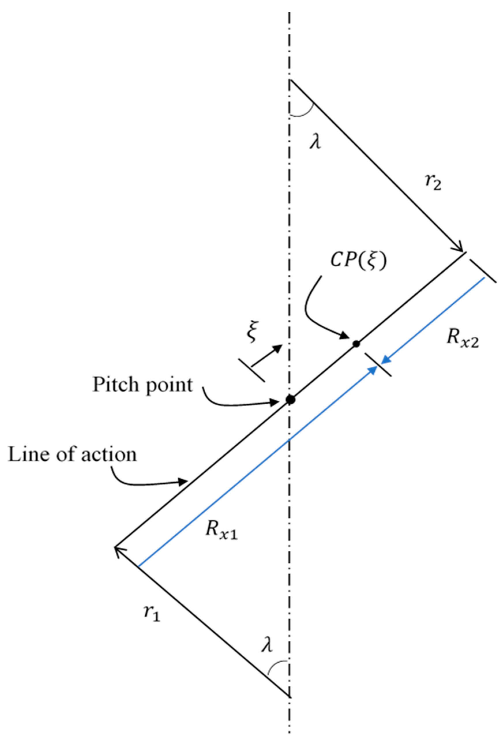
Figure 1 is used to illustrate the method of determining the radii of curvature for the teeth surfaces in contact in terms of the contact position
. This position is defined as the distance from the pitch point along the line of action, and it is positive in the direction shown in this figure. Once the contact position, CP
, is identified, the radii of curvature can be determined by the following equations, which can be easily derived using the triangles illustrated in
Figure 1.
where,
and are the radii of the base circles of the two gears.
is the pressure angle.
is the distance from the pitch point along the line of action.
and
are the radii of curvature of the teeth surfaces at a given contact position.
Figure 1.
Radii of surface curvature in terms of the distance from the pitch () along the line of action. is the contact position along the line of action in terms of .
Figure 1.
Radii of surface curvature in terms of the distance from the pitch () along the line of action. is the contact position along the line of action in terms of .
The equivalate radius of the relative curvature in the tangential direction to the teeth surfaces is
This radius will be used later (in addition to the curvature due to the flank modification) in determining the undeformed gap between the teeth surfaces.
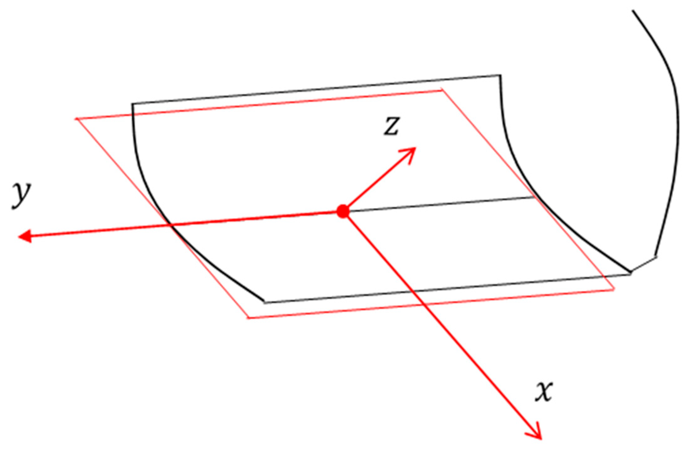
Figure 2 shows the tangent plane of the tooth surfaces at a contact position along the path of contact. The
x-axis is normal to the line of action in the illustrated direction, where
at the position shown. The
y-axis acts along the face width, and
at the middle of the face width. The normal axis of this plane is the
-axis, which is in the direction of the line of action, and the thickness of the lubricant is identified in this direction. The entrainment speed relative to the contact position is in the
x-direction of the
x-
y plane, which can be determined after calculating the surface speeds relative to the contact position using the following equations.
where,
and are velocities of the pinion and the gear teeth surfaces relative to the contact position.
is the entrainment velocity relative to the contact position.
and
are the angular speeds of the two gears.
Figure 2.
Tangent plane to the teeth surface at a contact position. Single tooth is shown for the purpose of clarity.
Figure 2.
Tangent plane to the teeth surface at a contact position. Single tooth is shown for the purpose of clarity.
1.2. Longitudinal Crowning of the Gear Teeth
The continuous changing of the operating conditions in wind turbines, such as the change in speed and the working under extremely heavy loads, will certainly affect the transient contact in the gear meshing cycle. For example, the angular misalignments between the input and output shafts, which may result from the heavy transmitted load, cause severe negative consequences on the teeth’s edges, affecting the system’s durability due to the inducing of fatigue spalling [
25]. Changing the geometry of the contact, mainly over the edges zone, is illustrated in this section to elevate the level of the lubricant thickness. Such a modification will be examined in detail later to evaluate the effectiveness under heavily loaded conditions of wind turbine spur gears.
Figure 3 shows spur gear teeth, and
Figure 3a illustrates a typical spur gear with unmodified teeth flanks [
26]. In such a case, the resulting contact is a line contact problem. Changing the flank profile using a curved surface, as shown in
Figure 3b, transmits the contact problem to a point contact. In contrast to the former case, the point contact problem requires that the surface curvature and the pressure gradient in both directions have to be considered in the solution of the elastohydrodynamic problem of spur gear teeth contact. The solution to the contact problem will be explained in the next section. Regarding
Figure 3b, the modification is maximum at the tooth edges and zero at the middle of the tooth flank. Using different values for the crown height (C) will change the resulting gap between the teeth surfaces, which will be examined in the full transient solution of the gear meshing cycle.
Figure 4 illustrates the parabolic curve along the face width used in this work when the crown is
. The maximum value of modification in this figure is
, which occurs at the edges and gradually decreases to zero at the middle of the face width.
2. Governing Equations
The solution of the elastohydrodynamic contact problem in spur gears requires a coupled solution for the two main governing equations, which are the Reynolds and the elastic film thickness equation. If the tooth flank is not modified (there is no curvature in this direction), the one-dimensional Reynold equation is used in the solution, as the pressure gradient along the face width is ignored, producing a line contact problem. Modifying the tooth flank, as explained previously, produces a curvature along the face width in addition to the curvature along the tooth’s involute profile. This means, in other words, that the pressure gradients in both directions of the solution space have to be considered, and a point contact solution is used in this case. The contact problem in spur gears requires a transient solution as the surface curvatures, surface velocities, and load change significantly as the position of contact progresses throughout the meshing cycle. The Reynolds equation for the point contact solution considering the squeeze term (time-dependent term) is given by [
27]:
The elastic film thickness equation is
where,
: Constant.
: Teeth surface deformation at a position in the solution space.
: The undeformed gap between the teeth surfaces.
: Axis in the tangential direction to the teeth surfaces.
: Axis in the direction of the face width of the tooth.
: Mean entrainment velocity, which is given by , where and are the surface velocities of the pinion and the gear in the tangential ( direction, respectively, and , as there is no surface velocity in the direction.
The surface velocities for the pinion and the gear with respect to the contact position were given by Equation (4) previously. In the case of Newtonian oil behavior, the flow factors are given by
In this work, the non-Newtonian oil behavior is considered where the Johnson and Tevaarwerk [
28] relation is used. This relation uses the following non-linear form to relate the shear stress and strain rate.
The viscosity–pressure relation of Roeland [
29] in the form suggested by Lugt and Morales [
30] is used in this work, which is given by
where
.
The Dowson–Higginson [
31] equation is used for density–pressure dependency, which is
The determination of the three terms in the elastic film equation is explained here. In the non-conformal contact problems where the contact between spur gear teeth represents an example of this type of contact, the gap between the surfaces depends on the radii of curvature at each contact position, which was given by Equations (1)–(3) for the tangential direction. Therefore, the total undeformed gap, which is the first term in Equation (6), between the teeth surfaces is given by [
32]
where,
(see Equation (3)) and are the equivalent radii of curvature in the x and y directions, respectively.
The equivalent radius of the relative curvature in the
y-direction can be calculated using the following equation
where,
and
are the radii of curvature of the teeth surfaces in the y direction. These curvatures result from the longitudinal crowning of the gear teeth, which can be calculated as
where,
is the tooth face width, and is the crown value at the edges of the tooth.
It is worth mentioning that if the tooth surface is not crowned, the radius of curvature in the y direction becomes infinity (straight line) as becomes zero in this case. The teeth of the pinion are crowned only as it contains a smaller number of teeth.
The second term in Equation (6), which is the combined surface deformation of the teeth, can be determined by [
32]
where,
are coordinates in the solution space of the point where the deformation is required.
, : modulus of elasticity of the pinion and the gear materials, respectively.
, : Poisson’s ratio of the pinion and the gear materials, respectively.
The third term ( in the film thickness equation is determined in the iterative solution, which satisfies the load convergence criterion, as will be illustrated later.
4. Results and Discussion
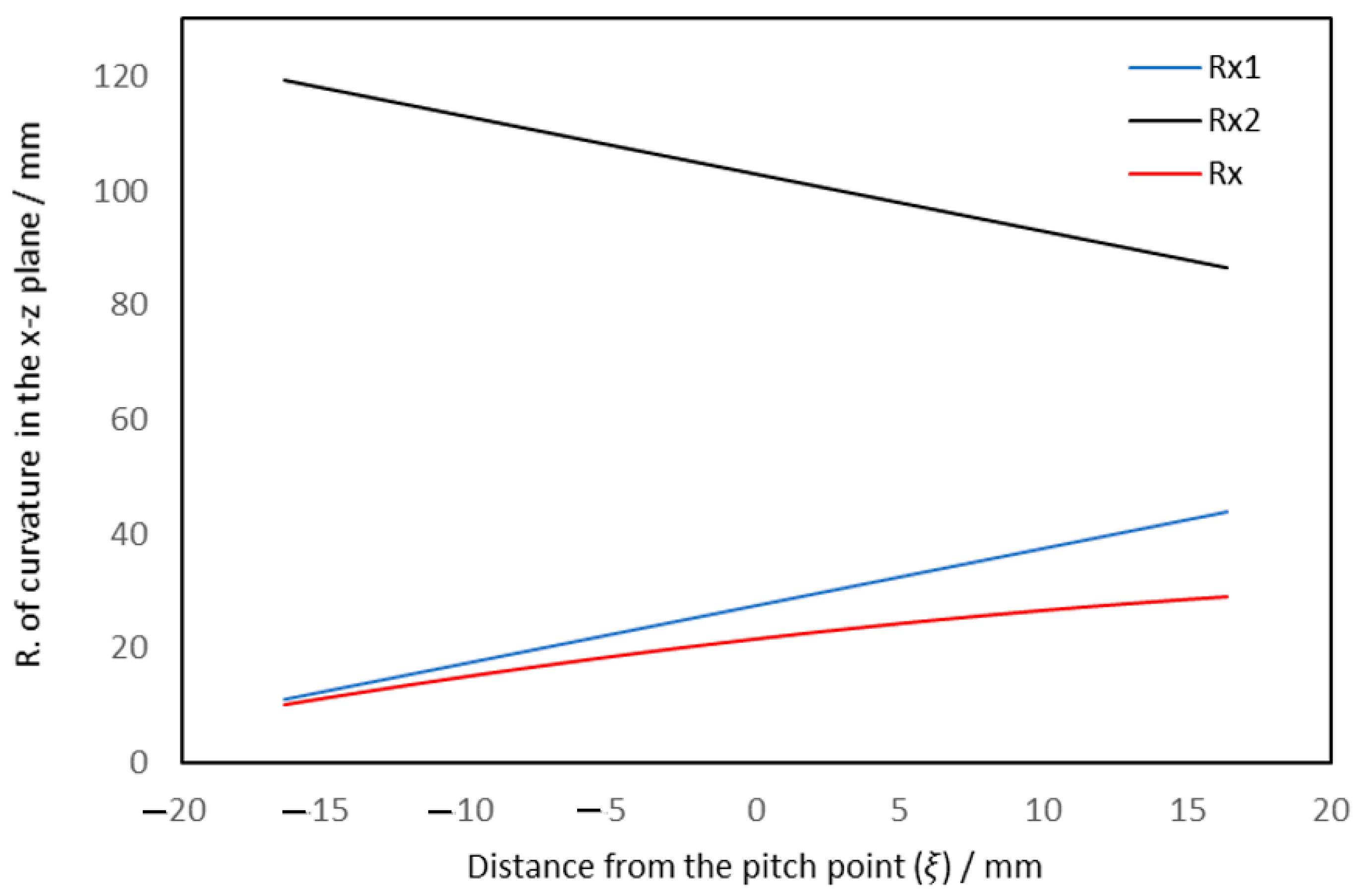
The determination of the undeformed gap between the gear teeth at each contact position depends on the radii of the curvature of the two surfaces.
Figure 6 illustrates the variations of the two curvature radii and the resulting radius of relative curvature along the line of action. The difference is very high between the two radii of curvature,
Rx1 and
Rx2, which is attributed to the difference between the size of the two gears, as explained in
Table 1. These values are used in the transient analysis of the teeth meshing cycle.
Figure 7 shows the variation in speeds of the surfaces relative to the position of contact along the path of contact in the tangential plane. The mean entrainment speed is also shown in this figure. It can be seen that the difference between the speeds of the surfaces is increased as the position of contact progresses away from the pitch point. The two speeds are equal at the pitch point. Therefore, the mean entrainment speed is equal to the surface speeds at this contact position.
Figure 8 shows the variation in
and
throughout the full meshing cycle of a pair of teeth in contact. The results shown in this figure are obtained for the case when the value of the maximum modification (crown) is
at the tooth edges. The maximum pressure (in black) values vary from 1.472 GPa at the first contact to 0.853 GPa at the last contact point. This variation is a result of the transient effects where the radius of curvature, surface velocities of both teeth, as well as the transmitted load are all changed at each contact point. There are sudden changes in the maximum pressure values when
. This distance along the line of action (or, in other words, the period of time from the meshing cycle) corresponds to the situation where there is only a single pair of teeth in contact. In such case, the load is at its highest value, resulting in these sudden changes in the pressure curve. The first change where the pressure rises is due to the start period of this single pair of contact, and the last change where the pressure drops illustrates the starting of the engagement of the second pair of teeth, which shares part of the maximum load. The participation in load sharing causes this drop in the maximum pressure value at this point. Furthermore, at this period of time, the contact continues to face the consequences of this transition to the single pair of contacts where the maximum pressure values fluctuate, as shown in
Figure 8. The corresponding minimum film thickness at each contact position is also shown in this figure (in red). The minimum film thickness variation reflects these transient effects and varies from 0.4426
at the first contact point to 1.044
at the last contact point.
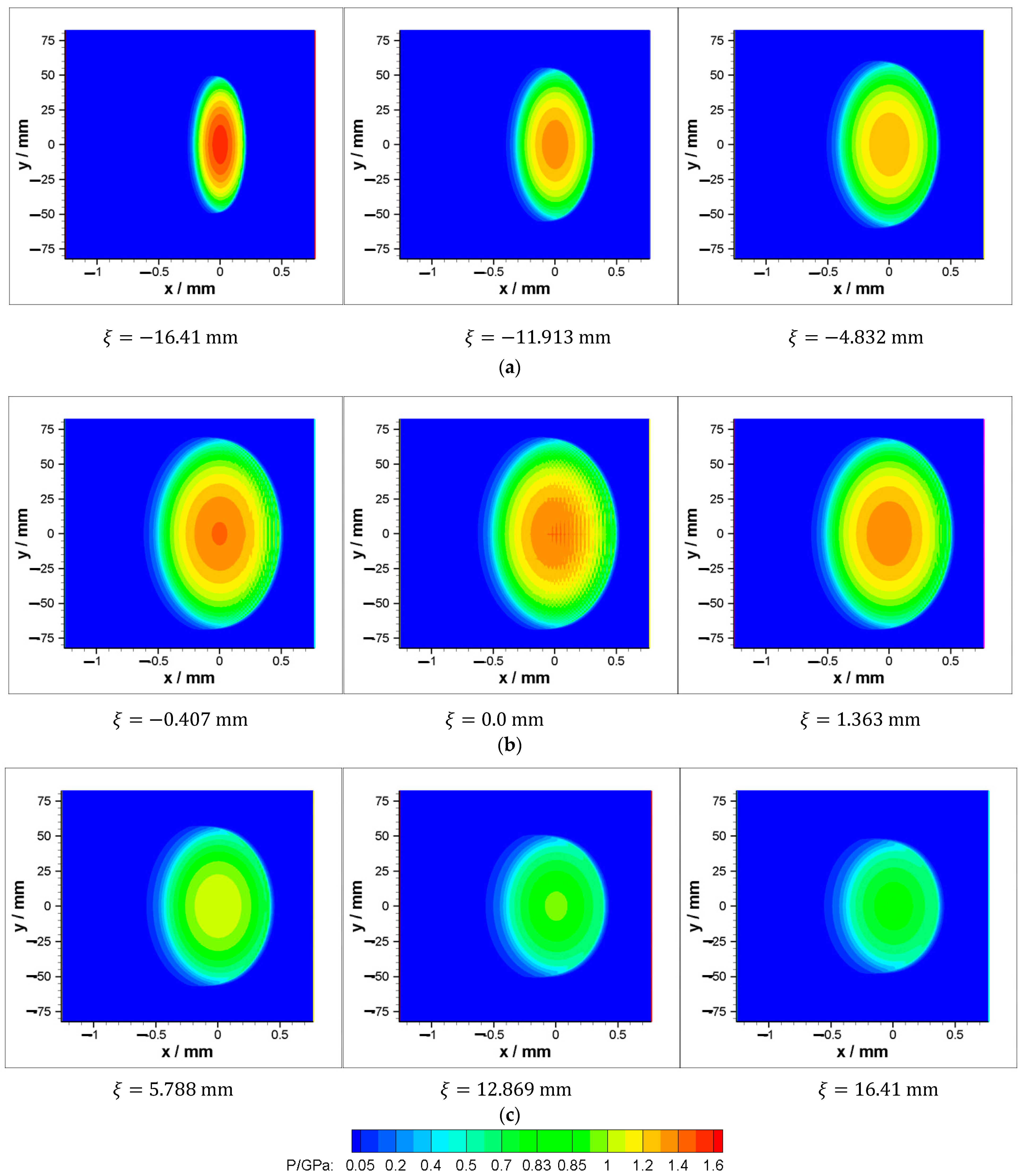
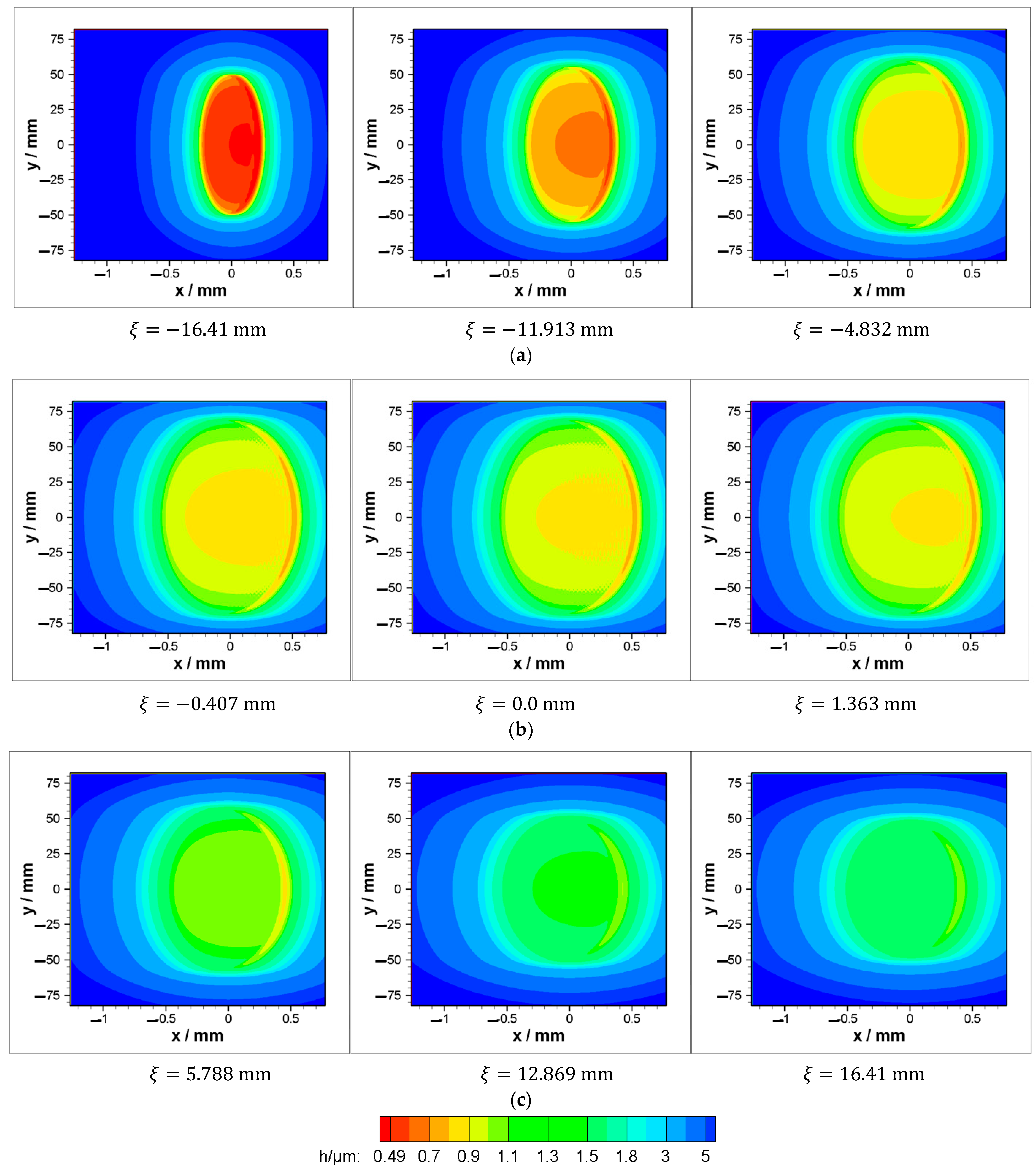
Figure 9 shows the pressure distributions at different positions throughout the meshing cycle when the crown is
. Nine positions are selected to explain the variation in the pressure contours due to the transient effects.
Figure 9a illustrates the contours over three positions in the first period of a double pair of teeth in contact,
Figure 9b shows another three contours at the period of the contact between a single pair of teeth, and
Figure 9c illustrates a further three contours of the pressure distribution over the second period of a double pair of teeth in contact. It can be seen that in addition to the change in the maximum pressure values through the meshing cycle that is shown in the previous figure, the area of the pressure contour is significantly affected by the position in the meshing cycle. The areas of the contours in the first and second period of a double pair of teeth in contact, as shown in
Figure 9a,c, are relatively small in comparison with the contours of the period of the contact between a single pair of teeth, as shown in
Figure 9b. The pressure distribution becomes closer to the tooth edges, where
for the contact in all three contact positions shown in
Figure 9b (single pair of teeth in contact). In other words, changing the crown value may result in more aggressive behavior in terms of edge contact, particularly in the severe operating conditions found in wind turbines. Therefore, the effect of crown value on the pressure distribution requires more investigation to ensure safe operation under a wide range of operating conditions. This outcome will be further investigated later in terms of the distance from the tooth edges where the pressure values are zero, which represents evidence for preventing edge contact.
Figure 10 shows the corresponding film thickness contours at these nine positions, where a horseshoe can be seen in all these figures, as is typical for an elastohydrodynamic lubrication regime. It can be seen that crowning the gear teeth elevates the film thickness values close to the tooth edges, which reduces the possibility of edge contact.
The value of crown (C) was 50
for the results presented in the previous figures, as mentioned previously. The effects of crown value on the transient results are shown in
Figure 11. Several values are used, which are less than and greater than 50
. These values are 40, 50, 60, and 100
. It can be seen that increasing the crown value leads to an increase in the maximum pressure and reduces the film thickness in all cases. The maximum pressure values are
and
GPa when
, and
respectively. However, these increases will be shown later to have fewer drawbacks in comparison with the benefit of the relatively higher values of C in terms of the teeth edge contact. Mathematically, these are expected results, as increasing the crown height at the tooth edges reduces the area over which the pressure is generated for the same transmitted load. In such cases, the pressure values rise over this reduced area in order to have their integration results in the same transmitted load. The corresponding minimum film thicknesses for these crown heights are 0.4538, 0.4426, 0.4326, and 0.3885
respectively. It can be seen that in all cases, the minimum film thickness values are higher than 0.3
which is considered to be a relatively high level of lubricant layer in the authors’ experience in this field, as the gearbox usually operates in a much lower level of film thickness due to the well-known reasons.
The transient results presented in the previous figure (
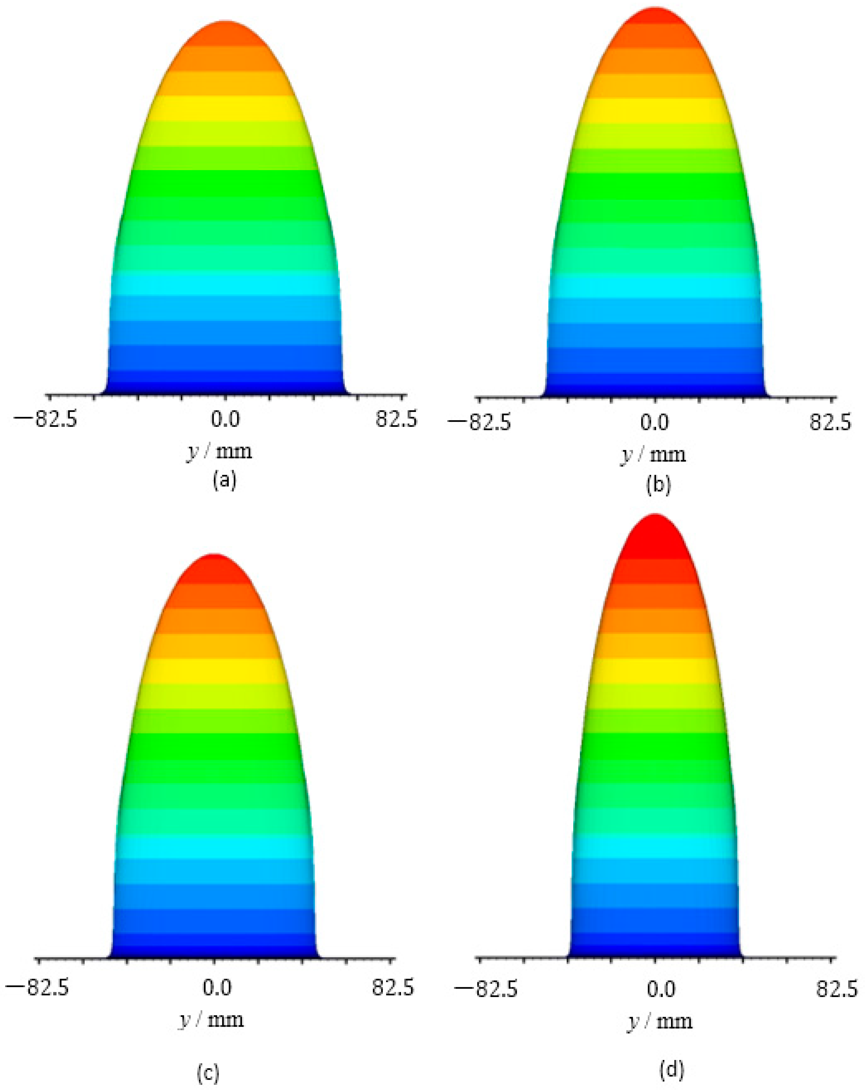
Figure 11) do not explain the extent to which the pressure is generated close to the edge of the teeth surfaces. Therefore,
Figure 12,
Figure 13 and
Figure 14 explain side views (in the
y-
z plane) for the pressure distributions to illustrate this concept for the whole considered range of longitudinal crowns.
Figure 13 shows the pressure distribution of a single pair of teeth in contact at the first period. As the load at this period of the contract is about one-third of the maximum transmitted load, it can be seen that the pressure is generated far from the edges
in all cases shown in this figure where different values of the crown are used. However, as the crown value increases, the pressure is generated over the area farthest from the edge. This is very clear when comparing
Figure 12a,b, where the crown values are 40 and
respectively. When the crown value is
, the distance of zero pressure along the
y-axis from both sides is about double the corresponding distance of the case when
, and the pressure is increased by only 18.58% (1.503 to 1.7823 GPa). It is worth mentioning that the resulting maximum pressure value is still, despite this increase, less than the pressure value if the film thickness is either dropped to the surface features or if there is any error related to the manufacturing or misalignment. However, when the crown is 60
the distance of zero pressure is also greater (about
) than the corresponding distance of the case when
, and the maximum pressure is only increased by 7.8% (1.503 to 1.6208). Similar behavior is also obtained for the case of
, where the distance of zero pressure increases (less increase in comparison to the case of
C = 60 and 100
) and the pressure slightly increases.
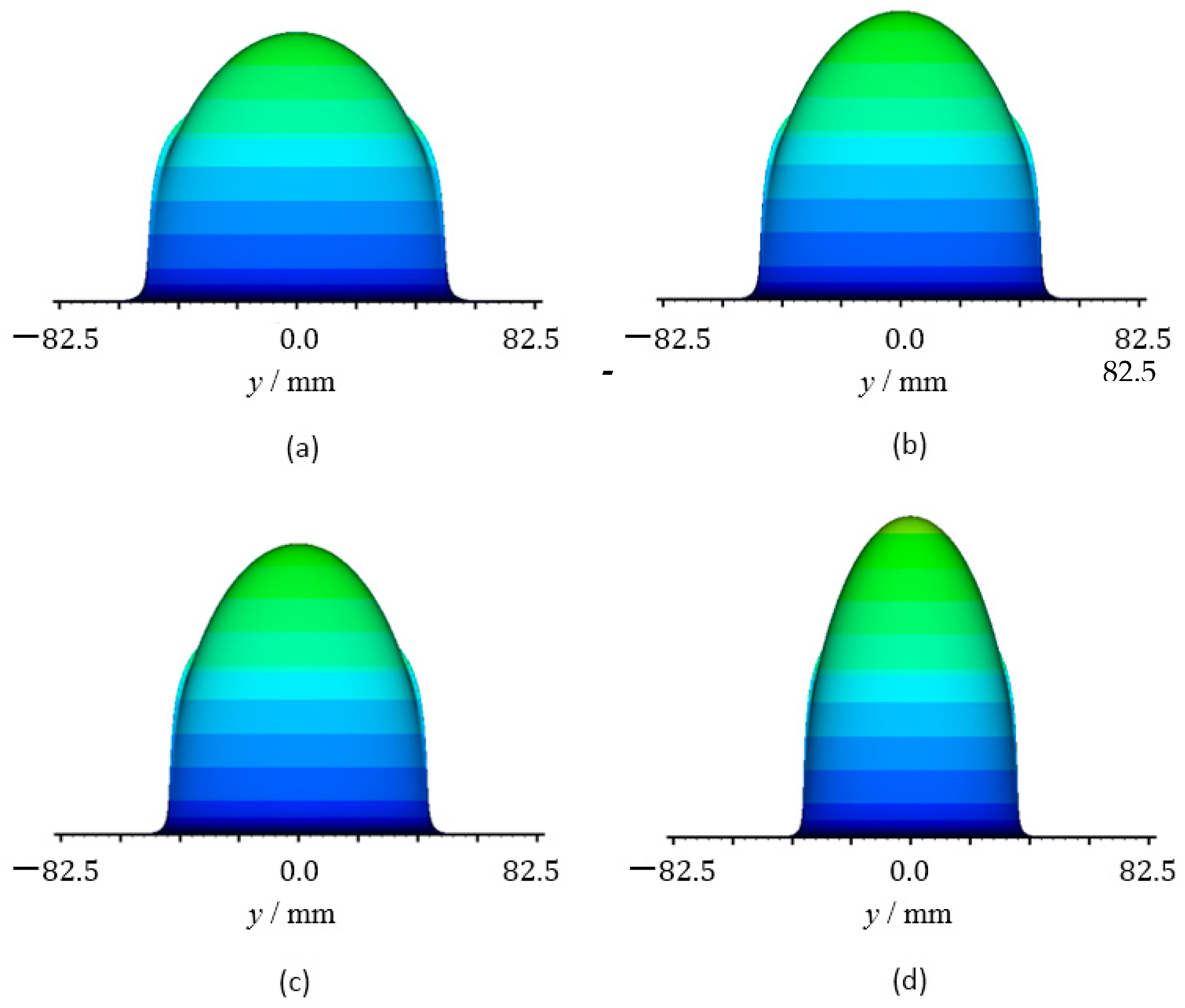
Figure 13 shows the corresponding results at the period of a single pair of contacts. As explained previously, the transmitted load at this period is at its maximum value. This load level (in addition to the other contact characteristics) affects the area over which the pressure is generated.
Figure 13a illustrates the pressure distribution when the crown height is
. It can be seen that two pressure spikes are generated very close to the teeth edges (close to
. This figure required an explanation in terms of the imposed boundary condition before solving the governing equations in their discrete forms numerically. The pressure values are set to zero at the boundaries of the solution space. Regarding this figure, the boundary condition at this side of the solution space is zero at
. The results in this figure illustrate that the pressure is generated just next to the boundary nodes. This means, in other words, that the pressure requires a larger distance to be generated over, but it faces zero values at the next node, which is imposed as a boundary condition. In this case, imposing the boundary conditions does not necessarily reflect the actual behavior at the edge of the teeth. Furthermore, a severe thinning of the film thickness, associated with an increase in the pressure value at the edges, is the expected result, which may lead to edge contact or at least increase the wear rate at the teeth edges. The results of this figure illustrate that the value of
is not sufficient to maintain the generation of the pressure away from the teeth’s edges. All the other values of the crown height,
, and
, clearly help in generating the pressure at a distance far from the teeth edges, as shown in
Figure 13b–d, respectively. The last case, where
, gives the best distance, and the pressure is only increased by 16.4% (1.40 to 1.63 GPa) in comparison with the case of
at this position in the meshing cycle.
The pressure distributions at the second period of a double pair of teeth in contact for different crown values are shown in
Figure 14. In general, there is similar behavior to the results of the first period of a double pair in contact that were shown previously in
Figure 12. All the considered crown heights are sufficient enough to maintain a generation of pressure away from the teeth edges, and the maximum pressure slightly increases as the crown height increases.
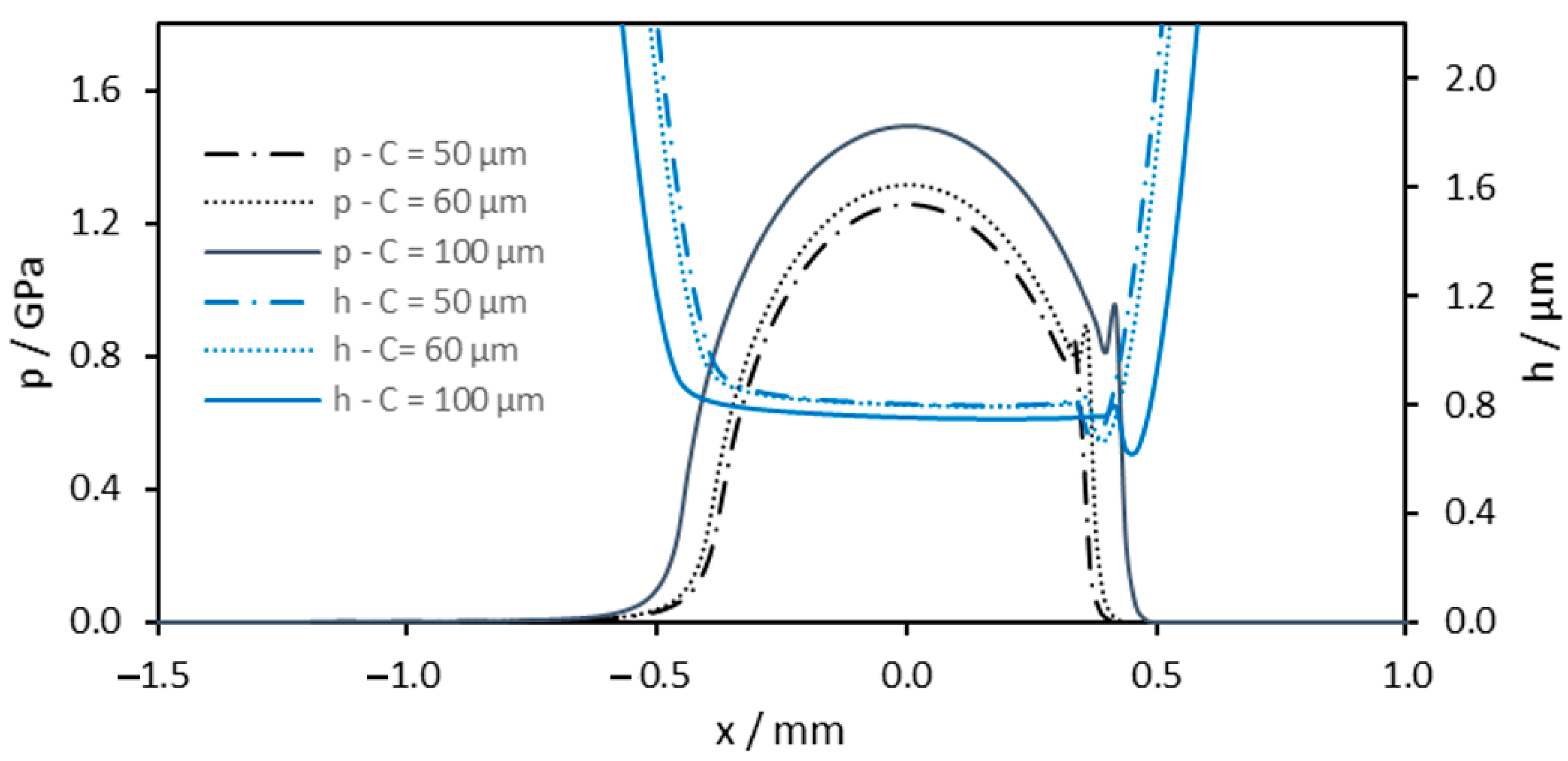
Figure 15 shows a further comparison between the film thickness as well as the pressure distributions at the center of the face width
when the crown height is 50, 60, and 100
All the distributions are typical elastohydrodynamic results. It can be seen that the pressure distribution when
is wider than the corresponding distribution when
and 60
. This is due to the fact that as the length of the area in which the pressure is generated over becomes shorter in the y direction due to the relatively high crown value, the area is extended in the x direction, which is shown in this figure to compensate for a part of this reduction. The other compensation part is clearly in the level of the pressure, which is again clearly higher in this figure than the corresponding pressure levels when
and 60
. On the other hand, the film thickness when
is slightly less than the corresponding film thickness levels when
and 60
. It is also clear that the film thickness is flat over longer distances when
for the same previously mentioned reasons.
The previous figures illustrate that when the crown height is
, the pressure is generated away from the teeth’s edges. This distribution helps in reducing the possibility of the thinning of the film thickness at the edges, which may cause an edge contact. Further investigation is performed for the effect of gear rotational speed on the elastohydrodynamic results when the distance is
.
Table 2,
Table 3 and
Table 4 explain these results when the pinion rotational speed is
,
, and
, respectively, where
is the designed rotational speed used in obtaining all the previous results.
Table 2 shows the maximum pressure and minimum film thickness values at the first period of a single pair of teeth in contact when
. It can be seen that as the rotational speed is reduced to
, the minimum film thickness value decreases by 49.66% (from 0.4426 to 0.2228
), and increasing the rotational speed to
increases the minimum film thickness by 37.16% (from 0.4397 to 0.6031
. In all cases, the level of the film thickness is greater than 0.22
which represents an additional benefit for the longitudinal crowing of the spur gear teeth, as it continuously separates the teeth surfaces by a sufficient layer of the lubricant despite the large change in the speed. The maximum pressure values are less affected by changing the rotational speed. Similar behaviors are also obtained at the position of a single pair of teeth in contact
shown in
Table 3 and at the position of
(
Table 4), which represents a position in the second period of a double pair of teeth in contact.
This work is focused on studying the variation in the tooth profile along the face width. Further investigation is required to incorporate the misalignment effect, the geometry change due to tip relief, and the surface features (roughness). Such a comprehensive model will represent a significant foundation to studying the fatigue failure of the spur gears in the considered large scale used in wind turbines. However, these important issues will be considered in the near future work. Furthermore, detailed comparisons are also required between the results presented in this work and the results of the misaligned case where the thinning in the lubricant is expected to be very clear at the edges of the teeth, which is also planned to be conducted in future work.

 ,
, 


