Review

A Review of Aviation Spline Research

1
School of Energy and Power Engineering, Dalian University of Technology, Dalian 116024, China
2
School of Control Science and Engineering, Dalian University of Technology, Dalian 116024, China
3
Key Laboratory of Intelligent Control and Optimization of Industrial Equipment of the Ministry of Education, Dalian University of Technology, Dalian 116024, China
4
AVIC Shenyang Engine Design Institute, Shenyang 110066, China
*
Author to whom correspondence should be addressed.
Lubricants 2023, 11(1), 6; https://doi.org/10.3390/lubricants11010006
Submission received: 27 November 2022 / Revised: 22 December 2022 / Accepted: 23 December 2022 / Published: 25 December 2022
(This article belongs to the Special Issue Wear Prediction in Aeroengine Rotor System)

Abstract

:
Splines are irreplaceable in high-speed aviation fields due to their simplicity, reliability, and high specific power. Aviation splines are not only subjected to severe operating mechanical loads, but also sometimes operate under grease-lubricated and non-lubricated environments. All of this results in aviation splines suffering widespread failures. Since the 1960s, many researchers have carried out much research on aviation splines. The wide range of research topics demonstrates the technical challenges of understanding aviation spline. This paper reviews the research of aviation spline from the aspects of failure form, fatigue strength, surface contact stress, effects of lubrication, and misalignment on wear, as well as experiments. Relevant research shows crowned splines can mitigate the spline wear process induced by angular misalignment, and oil-lubricating splines experience almost no wear. This paper also looks forward to the future development directions of aviation splines.

1. Introduction

Couplings are widely used in rotating machinery to transmit torque from driving machinery to driven machinery. There are various kinds of couplings. Among them, spline couplings make the structure simpler, more reliable and compact, and easier to install. Compared with other couplings, spline couplings have a larger contact area, higher bearing capacity, higher reliability, smaller stress concentration, and smaller strength weakening of shafts and hubs. Splines also perform well in terms of centering and guiding, which makes it simpler to correct installation errors and misalignments. As a result, splines are frequently utilized in transmission and connecting devices for rotating machinery [1].
In order to improve the safety, reliability, and power–weight ratio of transmissions, couplings are required to be rigorous in aerospace transmission devices. Splines are the only couplings that have been previously approved by military standards. A single-engine A-4 aircraft has 174 spline connections, not including splines internal to accessories and components [2].
Aviation splines bear complicated and severe torque loads during operation [3], including constant torque, periodic torque, additional cyclic torque, transient peak torque, and impact torque. In addition to these above torque loads, aviation splines also bear other mechanical loads, mainly including resonance load, misalignment load, and contact and friction loads. Furthermore, aviation splines often operate under conditions lacking lubrication and cooling. As a result, they often suffer conventional wear, fretting wear, corrosion, creep, fusion, and fatigue; moreover, they also sometimes suffer tooth and hub fractures.
According to a survey of the US Navy aircraft maintenance in the 1970s, 40% of fixed-wing aircraft and 70% of rotary-wing aircraft have spline problems. Aiming at the problem of misalignment contact wear and the failure of aviation splines, the US Navy maintenance warehouse has carried out systematic, comprehensive treatments of it, which has increased the mean time between failures of aviation splines from less than 500 h to more than 2000 h [2,4]. Since the 1970s, much research has been done on the design, contact, wear, fatigue, strength, and reliability of aviation splines. This paper reviews the relevant research from the following aspects: failure form, fatigue strength, surface contact stress, effects of lubrication and misalignment on wear, and experiments.

2. Spline Type and Characteristics

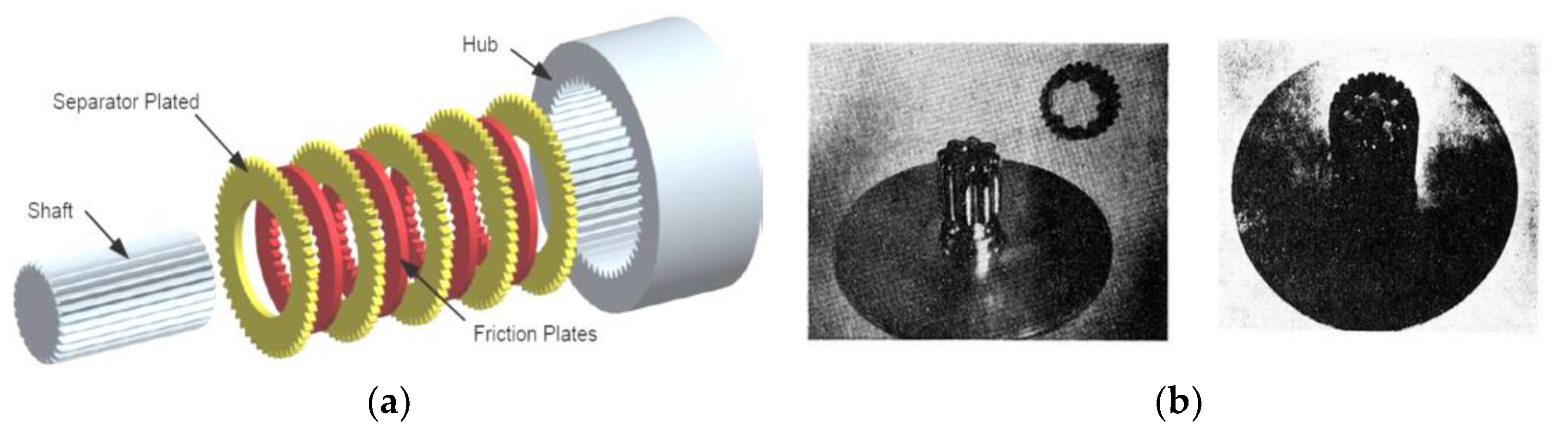
2.1. Classification from Spline Shape

(1) Classification from tooth profile of spline
According to the tooth profile of the spline, splines can be divided into involute spline, rectangle spline, triangle spline, and circular arc spline. As shown in Figure 1a, the tooth profile of the involute spline has an involute curve. The tooth of the involute spline always experiences a radial force, which makes the involute spline automatically self-centering and further guarantees that every tooth bears the same load. The involute spline has a high load capacity and is widely applied for connection with high load and high centering accuracy requirements. As shown in Figure 1b, the centering accuracy of the rectangle spline can make sure by minor diameter centering; the rectangle spline is used for connections with static or light loads. As shown in Figure 1c, the internal spline tooth profile of the triangle spline is a triangular shape, and the external spline is an involute shape with a 45° pressure angle. Triangle splines are mostly used for light load and static connections with small diameters, especially for thin-walled parts [2]. As shown in Figure 1d, the tooth profile of the circular arc spline is circular. The contact area and tooth thickness of the circular arc spline are much bigger than those of the involute spline, which effectively reduces fretting wear and stress concentration and improves load capacity. The circular arc spline is mainly used for connection with large misalignments.
(2) Classification from body shape of spline
According to the body shape of the spline, splines can be divided into external splines with an open end (see Figure 2a) and an adjacent shoulder (see Figure 2b) and internal splines with an open end (see Figure 2c) and an adjacent shoulder (see Figure 2d). These different spline body shapes influence the selection of mechanical processing technology. In addition, the spline may also be designed with a taper along the axis direction, generally with a 0.54° taper. This design can reduce the maximum stress of the adjacent shaft by 15%. In other words, it can increase the fatigue load capacity of splines by 15% [3].

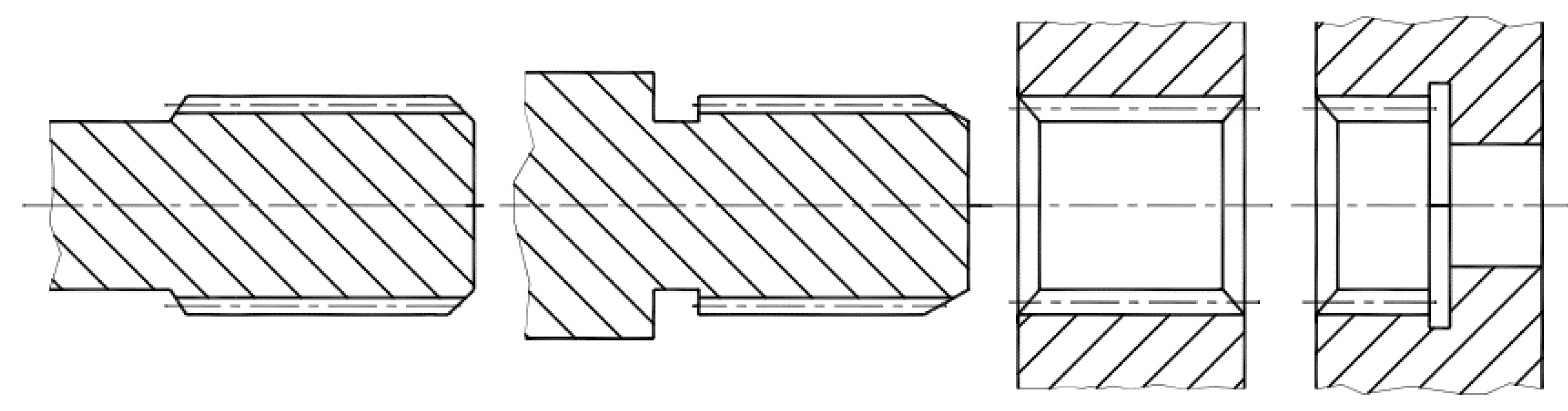
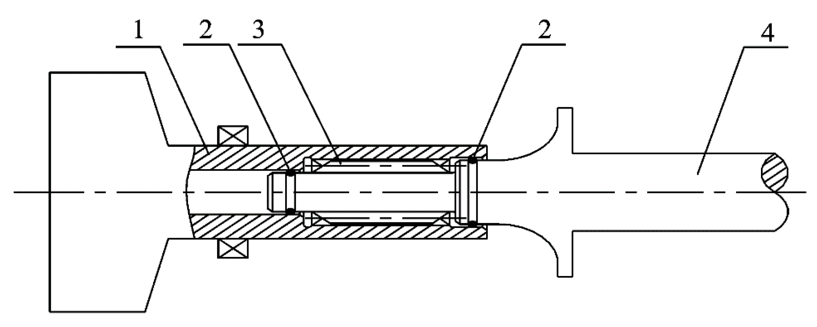
2.2. Spline Classification from Function and Positioning Mode

Splines can be divided into single-stage and multi-stage spline coupling, depending on their functions. The multi-stage spline can reduce torque fluctuation to a certain level and compensate for significant misalignment. Figure 3 shows two representative multi-stage splines (i.e., multi-stage splines with friction plates or a spline sleeve). As shown in Figure 3a, when applying an axial force on the multi-stage spline with friction plates, contact and friction would generate between the internal and external splines, which further transmit torques between the spline shaft and the spline sleeve [5]. As shown in Figure 3b, this type of multi-stage spline inserts a spline sleeve (ring) between the internal and external spline. Such a spline sleeve can be made of various materials, such as metal and nylon [6].
Splines can be divided into fixed and flexible splines according to Dudley’s method for calculating the bearing capacity of involute splines [7]. The fixed spline can be shrink-fitted or loosely fitted, but both ends have piloted rings to keep the spline from rocking. The rocking would result in a small amount of axial movement, which further leads to spline wear. A typical fixed spline is shown in Figure 4 [8].
Fixed splines are commonly used in the low-pressure rotors of aero engines to achieve stable and reliable torque transmission between low-pressure turbine rotors and fan rotors. The fixed splines used in aero engines are also called sleeve–tooth connection structures, as shown in Figure 5. The spline shown in Figure 5 is centered by cylindrical surfaces, and its axial direction is locked by an axial main locking nut [9].
When a flexible spline is not perfectly aligned, some rocking motion can occur, resulting in spline wear. Flexible splines are widely used in aero engine accessories, such as floating/semi-floating central driving shaft splines and fuel pump splines, as shown in Figure 6 [6]. These floating splines are typical flexible splines with two ends fixed to different boxes. Straight-tooth flexible splines can accommodate only a minor angle misalignment before wear becomes a significant issue. Splines such as crowned splines are advised for large misalignments to reduce stress concentration and spline wear.

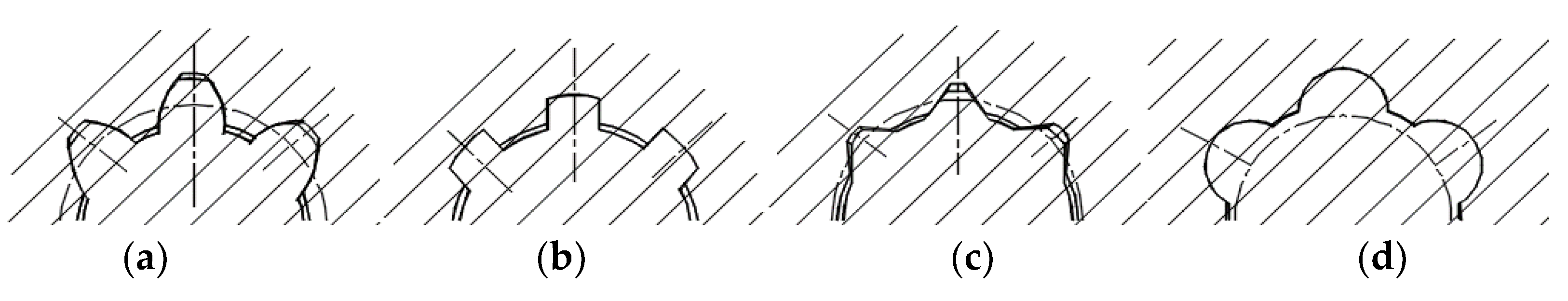
2.3. Spline Classification from Modification

Tooth modifications along the axial orientation are often used to improve the contact properties of misaligned splines. These tooth modifications can prevent stress concentration. In general, tooth modifications are performed on the external spline, and the internal spline remains unchanged. Splines with tooth tip centering are usually modified in the top axial direction, while splines with tooth side centering are usually modified in the tooth axial direction and maintain an involute profile. Splines with the second type of tooth modification are called involute crowned splines, abbreviated as crowned splines [10]. As shown in Figure 7 and Figure 8, the crowned tooth surface of crowned splines enhances the friction and wear condition of the tooth surface and reduces noise compared to common splines. It also prevents edge extrusion and stress concentration misuse in a misaligned state. In addition, the internal and external splines are conveniently disassembled and assembled due to the flared shape of the external tooth end.
Crowned splines are very useful for angular misalignments. However, the crowned splines are not suitable for aligned conditions. Under aligned conditions, splines with extensive crowned modifications would suffer high stress concentration and potential tooth breaking. For aligned conditions, as shown in the second diagram of Figure 7 and Figure 8, crowned splines have smaller contact areas compared with straight splines. Straight splines have larger contact areas to decrease contact stress.
There are several classifications of aircraft splines from differing perspectives. Aviation splines can also be divided into spray-lubricated, oil-mist-lubricated, grease-lubricated, and non-lubricated splines, as well as continuous-lubricated and clearance-lubricated splines.

3. Failure Form and Fatigue Strength of Spline

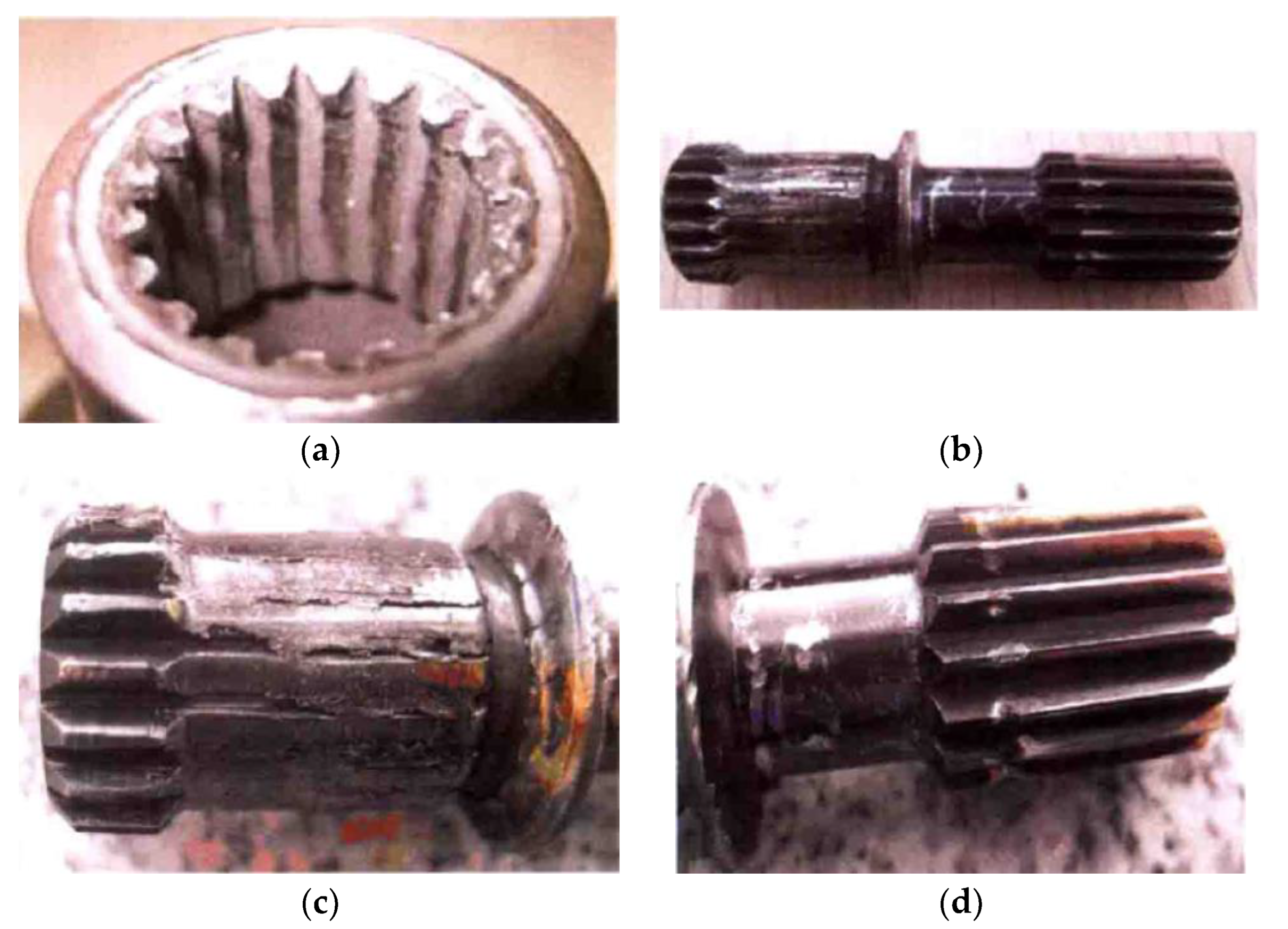
3.1. Main Failure Forms of Spline

The primary causes of spline failure include wear, damage, or excessive surface stress due to vibration, material, lubrication, misalignment, and surface cleanliness. The secondary causes of spline failure include fractures resulting from overload, interference, and fatigue [11]. Worse yet, inaccessibility due to space constraints and design issues makes spline repair and replacement difficult and maintenance expensive. The main failure modes of splines with different lubrication methods and extremely misaligned splines are shown in Table 1 [12].
The statistics in Table 1 show that failure modes are different even when splines are lubricated with grease and oil. Common failure phenomena in splines and their corresponding causes are shown in Table 2.
Fatigue strength is the main factor for spline failure, and Chen [13] summarized the failure modes of aero engine accessory drive systems, as shown in Figure 9. The results show that nearly half of failures are fatigue failures. In addition, Cuffaro et al. [14] conducted experimental tests on the damage modes of common splines and crowned splines. They investigated the effects of parameters such as clearance, surface roughness, lubrication condition, and angle misalignment on tooth surface damage. Their results showed that crowned splines have a completely different wear pattern compared with straight splines, and surface damage on crowned splines is greatly influenced by misalignment and lubrication states.

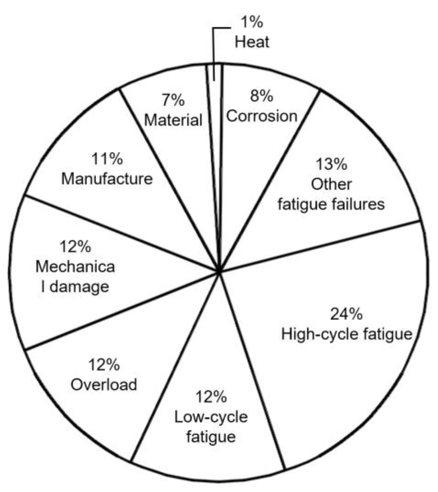
3.2. Spline Fatigue Failure

In aero engines, splines are often used to connect turbine rotors and compressor rotors. These splines experience large driving torque and high working speed, facing the risk of fatigue failure. The joint research and development center of the University of Nottingham and Rolls-Royce has conducted long-term research on the fatigue of aviation splines. Leen et al. [15] predicted cracked spline fatigue life using the Smith–Watson–Topper (SWT) method. The results showed that loading mode would affect the failure mode, and the overload torque in the main cycle would lead to low-cycle plain fatigue failure. They found crack initiation occurs outside the tooth contact regions at the high-torque position of the externally splined shaft. Wavish et al. [16] carried out experimental research on the fretting fatigue of splines and found that the critical spline crack occurs at the tooth edge and migrates from the surface. Ding et al. [17] simulated the cracks caused by fretting wear damage through experiments. Tjernberg [18] deduced the stress concentration factor nearby the root region without considering root deformation. The finite element analysis showed that the spline stress is concentrated in the tooth root, where fatigue cracks may occur. Uniform distribution of axial load can reduce the stress caused by increased load and improve service life.
Xue et al. [19] proposed a new damage accumulation algorithm by ignoring the location and direction of fatigue based on the traditional SWT method. Chen [13] studied the influence of spline structure parameters on the bearing capacity. He also evaluated the fatigue life of the aero engine accessory spline. Hu et al. [20] analyzed the causes of spline shaft fracture failure from the point of view of material and process. They found that the Widmanstatten structure produced by improper cooling rate would reduce both the fatigue strength and hardness of components. Liu [21] analyzed the fracture of a broken spline shaft and found that resonance is the root cause of the torsional fatigue fracture of splines. Kang et al. [22] analyzed the cause of spline shaft breakage of a generator for an unmanned aerial vehicle. They found that excessive radial excitation force of the spline caused by the deviation of installation axiality is the main cause of fatigue breakage. Zhao et al. [23] studied the failure modes and causes of vehicle drive shaft faults by checking the macro- and micromorphology and chemical composition of the fracture surfaces. The results showed that fatigue is the main cause. The stress concentration caused by the small geometrical dimensions of root rounded corners and unreasonable manufacturing tolerances accelerated the initiation and propagation of cracks.
The fatigue failure of splines is often caused by the increase in power, the weight limitation of aviation splines, as well as the complexity of the service environment and load. The main way to reduce fatigue failure is to improve contact stress distribution and fatigue strength of the load cycle through spline modification. In addition, improving the spline design level, adopting more advanced material and surface modification methods, improving manufacturing accuracy, and improving assembly processes are also effective ways to reduce spline failure probability.

3.3. Spline Strength and Bearing Capacity

With the continuous increase in the thrust-to-weight ratio of aero engines, the spline–power ratio (power-to-weight ratio of splines) has improved and almost approached the material strength limits. For conventional involute splines, their contact stress should meet the tooth surface contact stress, tooth root bending stress, and tooth root shear stress specified in the national standard for splines. The national standard for spline bearing capacity mainly includes GB/T 17855-1999, Dudley’s method, DIN5466, and TOCT 21425-75.
To prevent stress concentration, fretting cracks, and fatigue damage, splines should take into account the stress distribution and cyclic stress under load circumstances and service cycles in addition to satisfying the fundamental standard. In order to improve the uniformity of stress distribution and connection strength, Wang et al. [24] modified the splines after analyzing the contact stress of the spline tooth surface using both analytical and finite element methods. They discovered that the contact area of the spline tooth surface was not uniformly loaded. By changing the dimension parameters of involute splines, Chen and Zhu [25] analyzed the bearing capacity of involute splines, such as tooth surface compression stress, root bending stress, and root shear stress. They found that the engagement length of splines has great influence on the contact strength and root bending strength of splines. Hu et al. [26] analyzed the contact friction performance of an aviation involute spline pair using the finite element method. The results showed that contact stress and relative slip of the spline pair are not uniformly distributed, and the contact stress and relative slip near the tooth end are larger. They found that increasing contact length cannot improve the bearing capacity of the spline pair, and the ratio between the contact length and pitch circle diameter of the spline should be less than 1.2; the best ratio is 0.5. Chen et al. [27] carried out numerical calculations of friction work generated by contact of the spline pair teeth surface based on the finite element method. The results showed that the friction work increases with axis offset, but the increase rate gradually becomes smaller and smaller. Additionally, the friction work increases with the increase in the friction factor, and the increasing rate is relatively constant. Hong et al. [28] proposed a semi-analytical load distribution model for lateral engagement involute splines by extending the contact elasticity formula. Their model considered the bending and shearing of the tooth, the elasticity of the tooth root foundation, and the contact and torsional deformation of the tooth surface. Their model could quantify the effects of design variations and manufacturing errors.

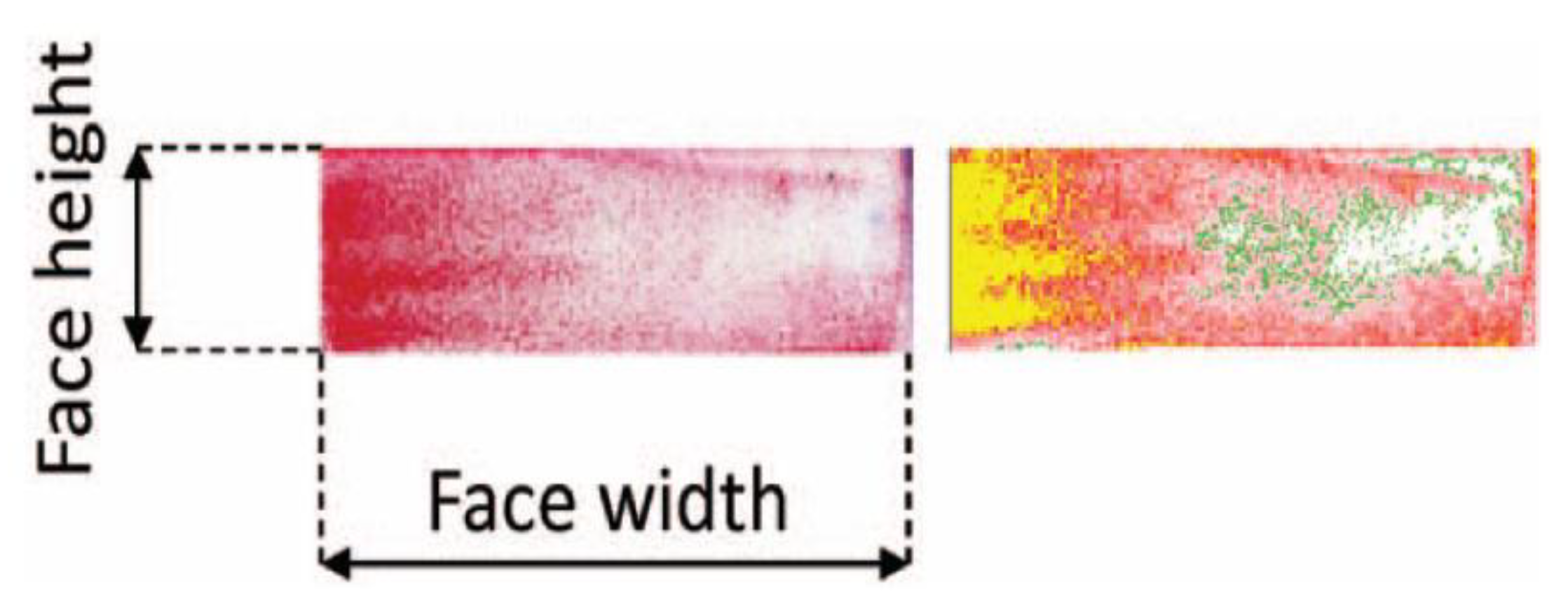
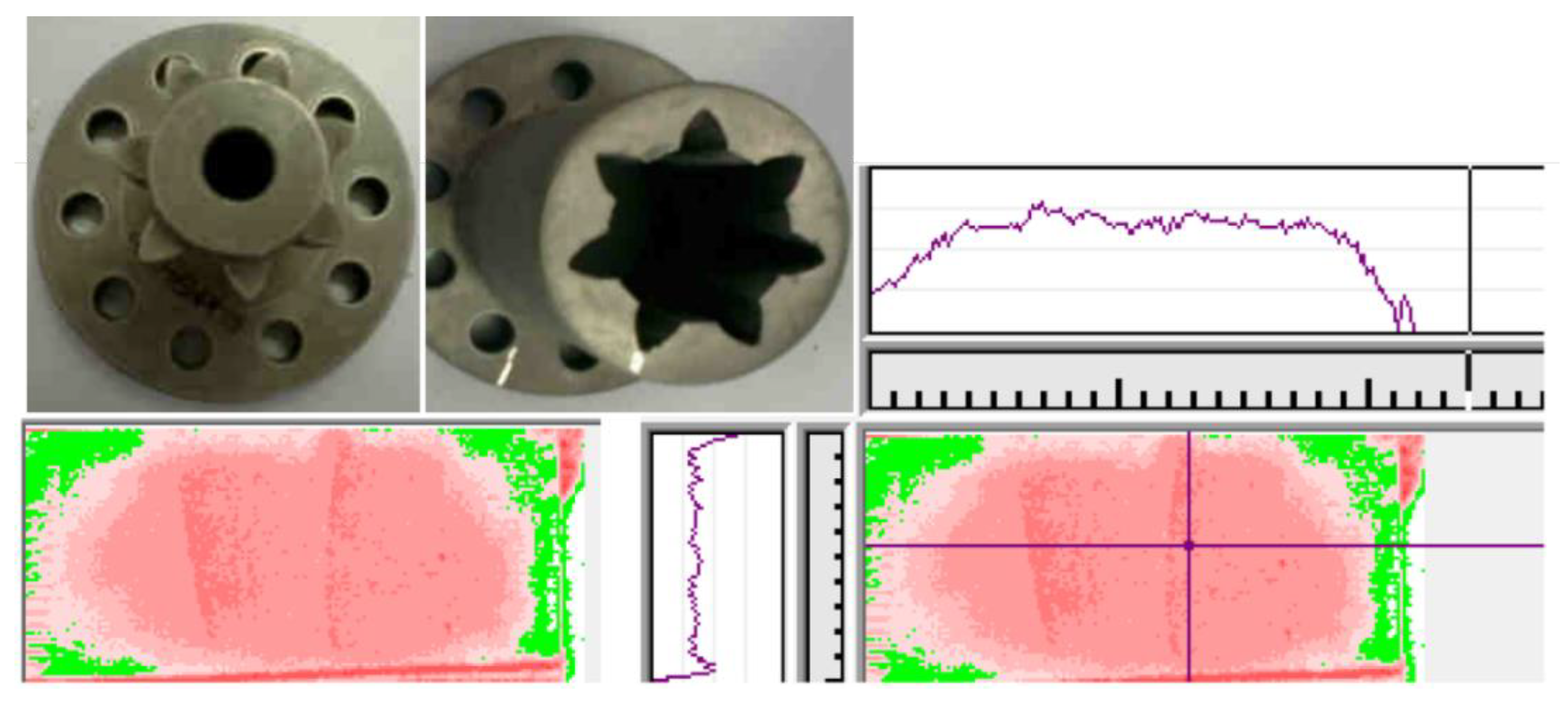
3.4. Contact Stress Distribution on Spline Surface

Currently, obtaining the stress distribution of the spline tooth surface and the trend in its variation with the misalignment, tooth side clearance, modification amount, and other factors has become a reality through finite element analysis software. Zhao et al. [10] analyzed the contact stress distribution of standard splines and crowned splines in aligned and misaligned states based on the commercial finite element software ANSYS. Hong et al. [29,30] studied the influence of misalignment, modification, helix angle, and machining error on the stress distribution of spline tooth surface using finite element simulation. Unlike finite element simulation, however, obtaining the stress distribution on the spline tooth surface through experimental tests is difficult. Vincenzo et al. [31] established a special experimental device to measure the tooth surface stress of aligned splines. They obtained the stress distribution using a special film. The film thickness was about 0.2 mm. The color intensity could be changed according to the change in stress, and the stress distribution was expressed by special software according to the film color. As shown in Figure 10, the stress distributions obtained using the finite element model match well with experimental results.
Cuffaro [32] measured spline contact stress distribution using the same film previously used in Ref. [31]. The tested spline specimens and the test results are shown in Figure 11. The results showed that the trend of contact stress distribution is consistent with simulation results, and the errors of stress distribution under different torques gradually differ between 2.8–15.6%. In general, the film can properly predict the distribution trend of contact area and pressure. Actual micro-contact characteristics of the spline were obscured by a relatively thick (0.2 mm) flexible film between tooth surfaces. Obtaining a satisfactory stress distribution under the condition of small tooth surface area and misalignment of typical aviation splines is difficult because of the limitation of film resolution.

4. Aviation Spline Wear

Tooth wear is the main problem of aviation splines. Early studies on spline wear were primarily conducted between 1970 and 1985. After receiving thorough treatments, the life of American aviation splines was significantly extended. Spline wear studies have ushered in another upsurge since 2010. China Aviation Engine Group has done a lot of research on improving the anti-wear performance of aviation splines.
According to the statistics of AVIC Shenyang Engine Design Institute [33], splines and accessories should be inspected gradually every 100 h. Twelve accessories and twelve splines were inspected during one inspection. As shown in Figure 12, five internal splines and eleven external spline shafts of fuel booster pumps were found to have worn severely, and they all needed to be replaced. The troubleshooting experience showed that the main problems of aviation splines are inadequate surface hardness, excessive axial movement value, excessive misalignment, and insufficient lubrication. However, the spline wear problem has not been effectively solved, and the root cause of spline wear and the mechanism of rapid spline wear are still unclear. Thus, it is urgent to carry out in-depth theoretical and experimental research.
Most damage of tooth-side centering splines is caused by wear. Spline wear can be generally divided into three stages, as shown in Figure 13 [34]. The first stage is a short running-in process, the second stage has an approximate constant wear rate, and the third stage has a strong damage effect. The results of the spline wear test showed that three wear stages do not always exist simultaneously, shown as Curves A and C in Figure 13. In addition to friction and wear parameters, the working state also plays an important role in the wear process. Splines with large torques wear more severely than those with large transverse forces [34].

4.1. Influence of Lubrication on Spline Wear

Mating external and internal spline teeth slip with each other when the spline runs at high rotating speeds. The slips may occur in the following three directions, namely axial, radial, and torsional directions. Friction and heating issues are very prominent when considering variables like misalignment and vibration, so splines require reliable lubrication [35]. Splines are often lubricated using grease, oil/oil mist, or no lubrication. Grease-lubricated splines are simple to operate, easy to maintain, and highly reliable. They also have a unique property of sealing teeth from the environment. Grease-lubricated splines have drawbacks in that they are greatly affected by working temperature and have poor grease continuity and retention. When the grease is thrown out or completely squeezed out due to centrifugal force, the friction coefficient between the mating spline teeth increases as a result of no lubrication. In addition, the oxide coating cannot be produced because grease prevents air from entering the spline tooth surface at the initial stage. In small misalignment states, the aviation spline generates very little heat, and its temperature rise mainly comes from the heat transfer from the attached shaft. Currently, few lubricating greases can work at temperatures above 121 °C. Grease lubrication is therefore inappropriate for the enclosed area because its heat is difficult to dissipate. Continuous oil/oil mist lubrication makes the heat output from the spline increase rapidly, so splines running at high speed with oil lubrication would still have greater continuous service performance. The disadvantages of oil lubrication include its high cost and the needs of additional pipelines, oil stations, and other auxiliary systems. What is more, the spline wear will be accelerated once impurities enter the working environment through the lubricating oil. The non-lubricated spline is often used in conditions with compact structure, low running speed, light torque, and high working temperature. Additionally, the spline can use intermittent or discontinuous lubrication, or the radial hole can be employed to direct lubricating oil toward the spline engagement point, and the lubrication can be achieved through capillary actions [36]. Although the lubrication mode has the above rules to follow, it also needs to be determined according to the actual structure and working environment.
Spline wear is a complicated process that can be either mechanical, chemical, or both. Mechanical wear can be significantly alleviated by selecting the correct lubricant. If the lubricant is unable to reduce the creation of wear debris, wear propagation will dominate the wear process. The hardness of oxides is often higher than that of the spline matrix. That is, if wear debris remains in the lubricant, it will instead aggravate spline wear and even lead to connection failure. Essentially, grease lubrication cannot play a positive role if the aim is to improve the service life of splines. According to laboratory tests [37], splines need to be cleaned and relubricated at least every 50 h of operation. For aviation splines, the downtime is unbearable, to say nothing of the high maintenance costs. Only oil lubrication can achieve a significant improvement because, in addition to friction characteristics, lubricating oil can wash away the wear debris and further achieve complete lubrication. A summary of the influence of lubrication mode on spline wear is shown in Figure 14 [34].
In-depth experimental studies on the spline wear process were conducted by Weatherford and Valtierra [38]. They studied the effects of crowned amount, misalignment, lubrication, materials, working temperature, and surface treatment on spline wear. The qualitative effect of lubrication on spline wear in the dry air environment is shown in Figure 15. They found that a suitable lubricant will create an induction phase at the initial operating stage, which considerably delayed spline wear. Rapid wear with a consistent wear rate will happen when the lubrication runs out or the spline surface is damaged. They also found that the wear rates are different when the lubricants are different. Mura et al. [39] added graphene to standard grease to produce a high-performance lubricant effect. The friction force of different grease graphene compounds was measured through experiments. The results showed that grease mixed with graphene could reduce the friction coefficient.
To sum up, the lubrication modes, lubricant parameters, and temperature have an important impact on spline wear. The individual operating environment and spline state must be taken into consideration while choosing a proper lubrication method and determining an acceptable cleaning and relubrication cycle.

4.2. Effect of Misalignment on Spline Wear

Although the good alignment of connected rotors is required by spline assembly standards, in practice, manufacturing and assembly errors, component tolerances, dirty assembly surfaces, wear, and cold and hot deformations together would lead to large misalignment. Misalignments can cause a number of problems, such as vibrations in the spline rotor [40], spline teeth breakage, scratches, cold deformation, wear, and pitting. Misalignment also generates considerable axial force. According to ARINC measurements, the axial force generated by significant misalignment is large enough to disengage the coupling. The axial force generated by a misaligned spline greater than 2 degrees can be as much as 900 N [2].
Curà et al. [41] established a theoretical method based on a non-finite element method to determine the exact number of engaging teeth and shared forces in involute spline couplings with parallel offset errors. Elkholy and Alfres [42] addressed that misalignment leads to a redistribution of the load on each spline tooth, which increases the maximum contact and bending stresses of the tooth. The uneven load on the tooth also generates tilting and friction moments, which will further transfer to bearings. Test investigations show that misalignment has a significant effect on spline reliability, wear, and life [4]. As shown in Figure 16, misalignment significantly increases spline wear, and a small increase in misalignment results in a sharp increase in wear and a sharp decrease in wear life. The most efficient way to extend wear life and decrease wear on splines, as well as the most efficient way to simplify spline design and lower lubrication and maintenance pressure, is strict control of misalignment. In view of the inevitability and severity of spline misalignment, Ref. [43] gives the requirements for misalignment control of couplings in rotating machinery.
In general, the magnitude of fretting between internal and external splines is far greater than that of the rotor connected by splines. Splines are often regarded as the representative of the fretting damage of complex components. Spline wear is inseparable from the vibration of splines. Many researchers have studied fretting wear, fretting fatigue, and plain fatigue caused by splines under actual load conditions [44]. The main mechanisms of micro-damage are fretting wear and fretting fatigue, which coexist in the same contact and can cause damage wear and contact-related crack initiation [45]. Jason [46] proposed a method for predicting the fretting fatigue life of a system that takes into consideration the material removed as a result of fretting wear. This method can predict some critical experimental phenomena, such as crack occurrence. Leen et al. [47] and Sum et al. [48] simulated the operating conditions of aero engine splines and analyzed the wear problems caused by fretting motion using computational contact mechanics and finite element methods, considering complex asymmetric loads and variable loads. Liu [49] found that wear can be reduced by improving the machining accuracy of the spline, reducing the spline fit clearance, and improving strength by heat treatment. Houghton et al. [50] proposed a method to predict the fretting fatigue life of aero engine splines and obtained the wear of splines under complex loads due to friction coefficient and speed. Curà and Mura [51] identified the fretting wear damage in actual working conditions by experiment using crowned splines. They found that the fretting wear is mainly caused by the relative motions between teeth with angular misalignments. The influence of torque and misalignment on spline wear is shown in Figure 17.

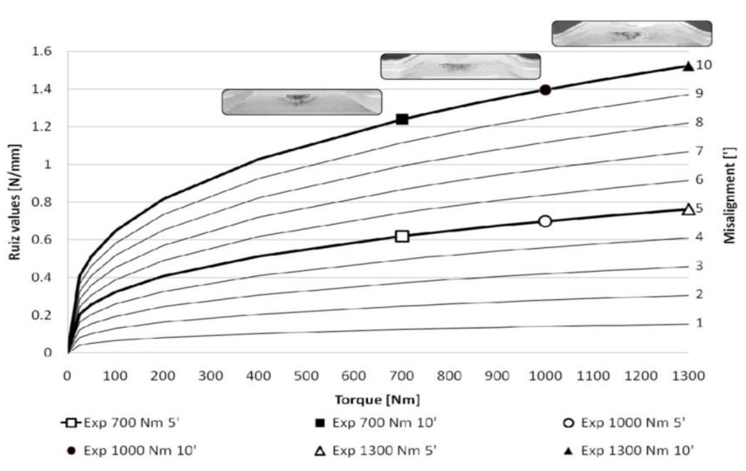
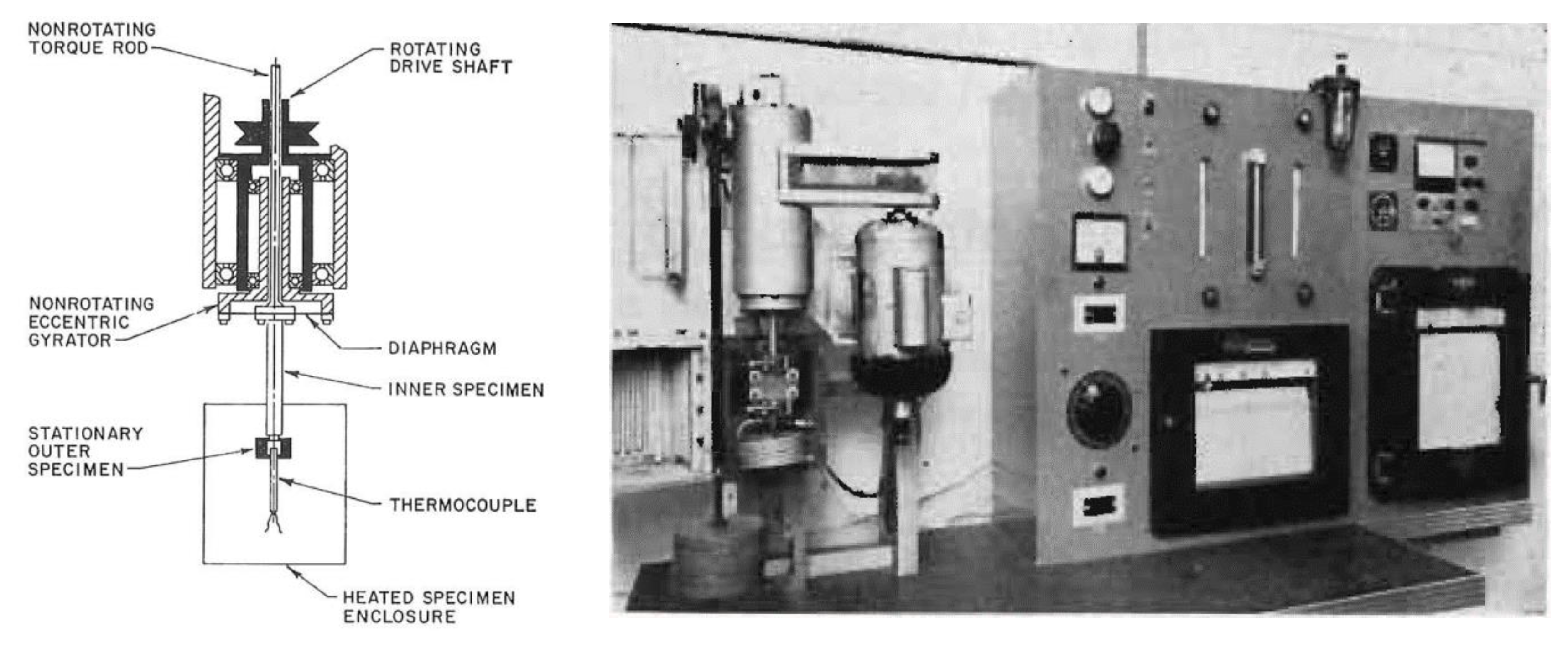
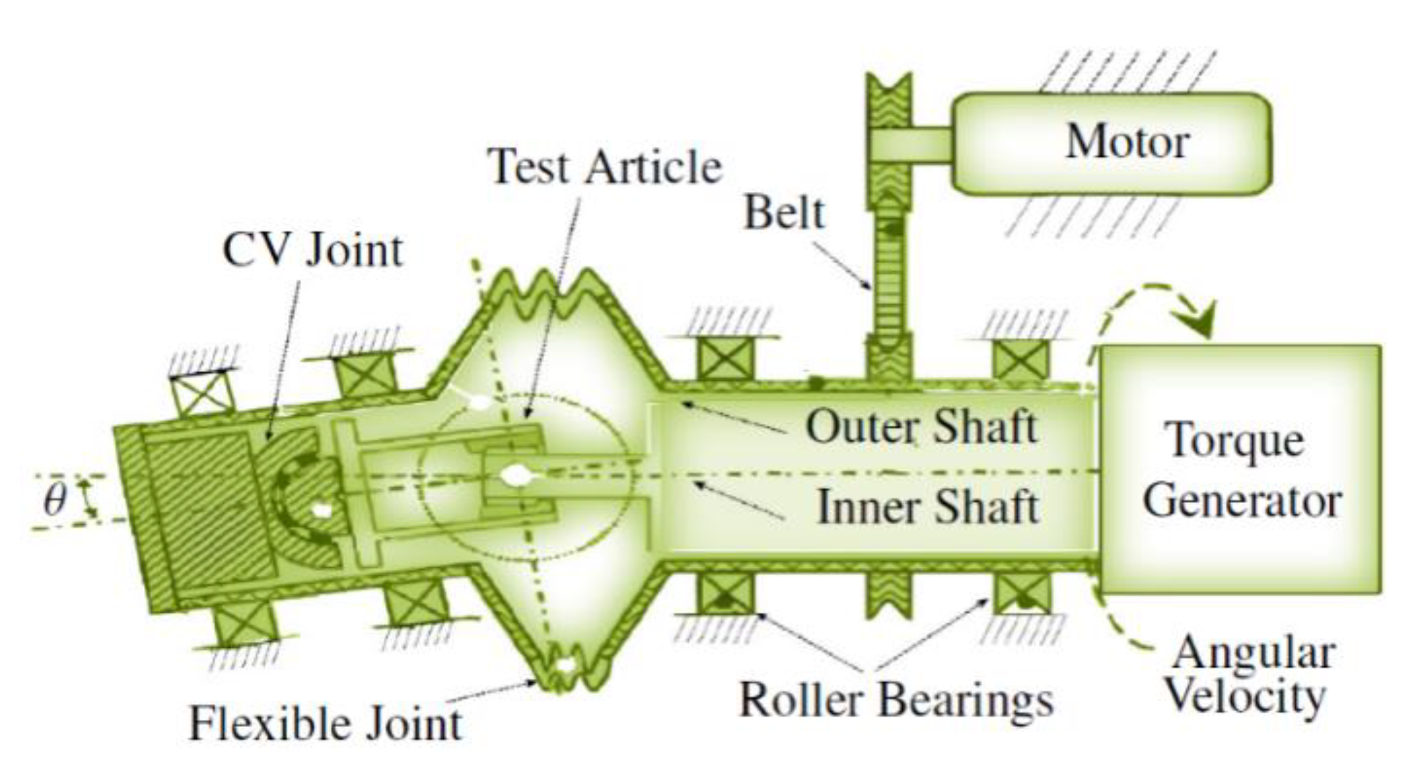
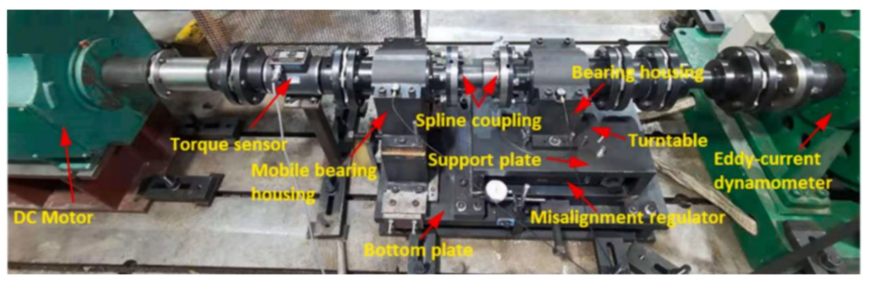
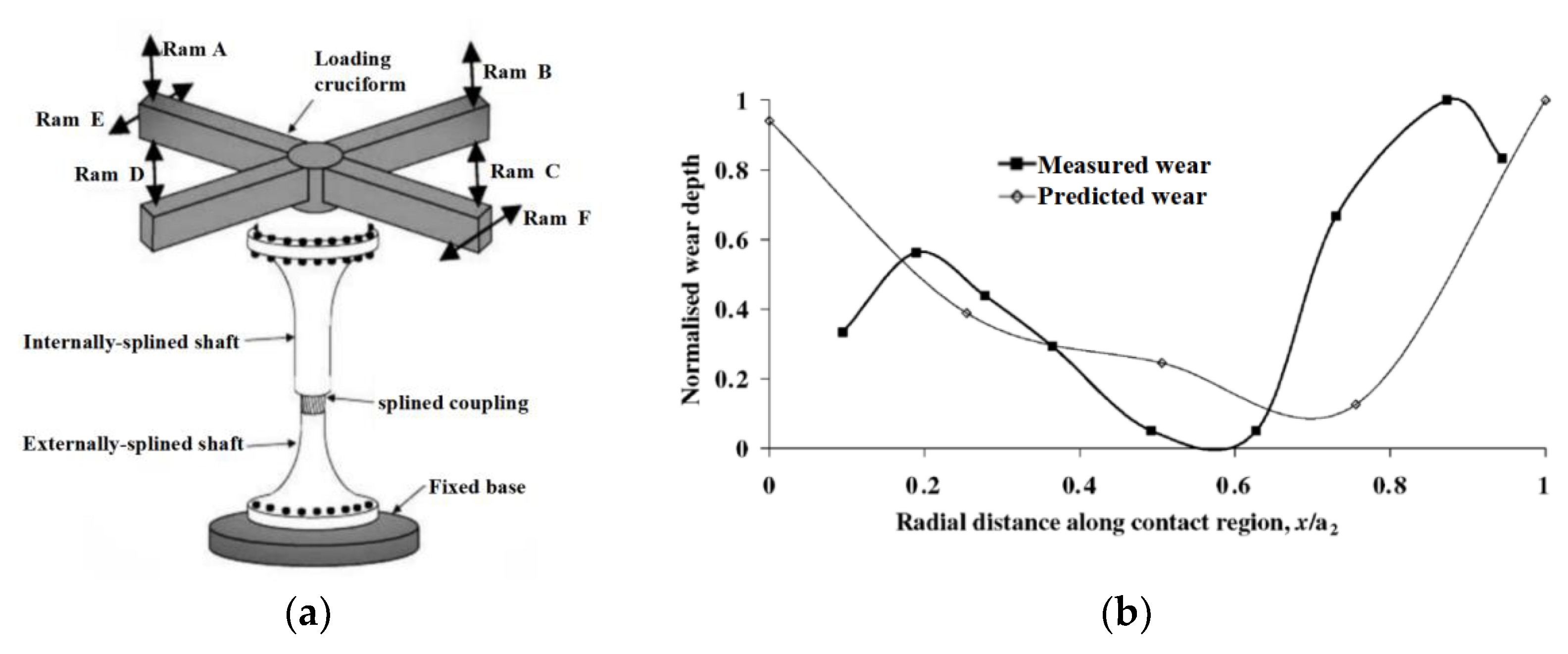
4.3. Experimental Study on Spline Wear

In the early 1960s, the US Navy Air Systems Command developed an aviation spline wear measurement test bench [37], as shown in Figure 18. The impact of operation temperature, lubrication method, material and surface treatment, spline structure parameters, and other factors on spline wear can be measured using that test bench. Three sets of spline wear tests have been developed, and the spline wear tests have been carried out for more than ten years. A large number of representative spline wear characteristics have been obtained. As a result, the service life of American aviation splines has been dramatically improved. Referring to the above spline wear test principle, Zhao et al. [52] and Sun [53] set up an aviation spline vibration wear test rig and carried out some spline wear experiments. The relative motion displacement and wear quantity of the aviation spline teeth under vibration circumstances were calculated using the Archard wear model.
For the fretting wear of high-power splines, Cuffaro et al. [31,54] developed a spline wear test bench, as shown in Figure 19. They experimentally studied the effects of misalignment, surface roughness, and lubrication on spline wear, and they studied the experimental methods for measuring and monitoring the surface pressure of spline teeth.
For the serious abnormal wear of aviation splines with misalignment, Xiao et al. [55] developed a spline wear test bench, as shown in Figure 20. The mechanism of misalignment on spline wear is discussed. They found that the contact stress at the spline edge increases with the increase in misalignment, which leads to abnormal wear at specific positions of the tooth surface.
Ratsimba et al. [56] developed a spline fatigue test bench to measure the fretting fatigue and wear of a reduced-scale aero engine spline, as shown in Figure 21a. Horizontal actuators E and F provide cyclic torque, while vertical actuators A-D provides axial load and rotational bending torque. The test simulates the flight load through a combination of primary and secondary cycle loads. The main cycle simulates the full thrust state of the engine, and the secondary cycle simulates the small-amplitude superimposed load caused by centrifugal force/gyroscopic effect and engine casing deformation. The predicted and experimental results of spline wear are shown in Figure 21b. The results show that the predicted trend of wear depth along the spline axis is basically consistent with the test results. The wear at both ends of the spline is large, while the wear in the middle is small.
Hu [57] qualitatively studied the fretting wear of the spline tooth surface using a PNW-5 electro-hydraulic servo shaft torsional fatigue test bench. They experimentally studied the fretting wear of the tooth surface of modified and unmodified spline pairs to verify the effectiveness of sectional parabolic modification of tooth direction. Xue et al. [58,59] simulated the friction movement of involute cylindrical spline pair by using a rack plane spline pair according to the force form, friction, and wear characteristics of the aviation spline pair in the actual working process. They carried out friction and wear tests of the plane spline pair using an INSTRON 8872 high-frequency tension and compression vibration fatigue testing machine. Their results showed that the fretting wear of the plane spline pair occurs under fretting conditions due to the interaction of abrasive wear, oxidative wear, and adhesive wear. Finally, cracks are generated, which leads to the failure of the spline pair. Li et al. [60] developed a multifunctional wear test bench to explore the anti-wear properties of spline materials. Their research provided some experimental data for revealing the working mechanism and failure cause of material products.

5. Future Development Direction of Aviation Splines

The design, manufacture, material, strength, lubrication, maintenance, and other technologies of the aviation spline are basically mature. However, due to the continuous development of aero engines towards higher thrust, lower fuel consumption, lighter structure, and lower cost, the problems faced by aero splines and the future development direction remain the same, that is, extending their service life, reducing their weight, and improving their reliability. At this stage, the main problems faced by aviation splines are as follows:
(1) Misalignment control issues. From the dynamic perspective, misalignment is the main cause of local resonance or abnormal vibration of the spline–rotor system of the central drive rod of fixed-wing aircraft engines. It is also the main factor that causes self-excited vibration instability of the helicopter tail drive shaft. In view of wear, misalignment increases the relative slip of spline pairs and the local stress concentration on the tooth surface, resulting in sharp spline wear. Therefore, it is a long-term and arduous task for aviation splines to accurately predict and effectively control the misalignment caused by design, manufacture, assembly, and service.
(2) Material handling issues. It is an effective way to improve the service life of aviation splines by strengthening the surface materials. On the basis of controlling the misalignment of splines, cyaniding, nitriding/carburizing, shot peening, and an efficient wear-resistant coating can efficiently moderate spline wear and lengthen service life for a given material and service load.
(3) Lubrication and cooling issues. As the combustion chamber and turbine of the aero engine adopt new materials and new cooling designs to improve the overall operating temperature of the aero engine jointly, spline heat dissipation is challenging. The increase in operating temperature can cause premature melting or dissipation of the lubricating grease in the spline or increase the temperature of the oil lubrication system. However, not all locations can adapt to the further increase in the lubricating oil temperature. In addition, the heat generated by the cyclic stress and vibration friction in the spline will lead to the decomposition of some lubricants, accelerate the oxidation of lubricants, and reduce the lubrication effect, thus leading to earlier corrosion and fatigue damage. Moreover, the grease used in helicopter tail drive shaft splines, for instance, is frequently subject to major failures like depletion, oxidation to powder, a marked rise in the friction coefficient, and even the self-excited vibration of splines. Therefore, spline lubrication and cooling are issues that need to be followed up with the development of aero engines.
(4) Reliability and capacity issues. Uneven stress distribution and concentration on the spline tooth surface caused by aviation spline misalignment/deflection, vibration, spline floating, and other factors considerably raise the risk of spline failure. Extreme operating conditions of high-performance aero engines, such as sudden external force, maneuvering flight, blade loss, and load stagnation, may cause a sudden torque increase in splines. Therefore, the accurate design and calculation of spline bearing capacity are particularly important. Spline bearing capacity design and reliability prediction under extreme operating conditions are still significant issues for aviation splines [61].
(5) Fatigue life prediction issues. High-cycle fatigue in long-term stable service and fatigue cycle life after spline wear are always faced with problems in the development of long life and high-reliability splines. Aviation spline wear is a slowly changing process. Contrary to gears in the accessory drive, which has the cycle number fatigue limit S-N fatigue curve, the fatigue cycle life of worn splines is not constant. Accurately predicting the fatigue cycle life is always an important task for long-life and high-reliability aviation splines.
(6) Experimental technical issues. Accurately simulating the complex load condition and operating environment of the aviation spline on the existing test bench is challenging, and there is a lack of a test bench that can run steadily for a long time to test the wear performance of the aviation spline. This is mainly due to the time-consuming nature of the spline wear test and the requirement for the high stability of the test bench. Therefore, it is necessary to develop efficient accelerated testing techniques, similarity testing techniques, and environmental impact testing techniques and methodologies. Future aviation spline experiments will also focus on the strength assessment of spline bearing capacity caused by extreme operating situations, such as load stuck owing to failure, abruptly unloading entirely, sudden misalignment induced by maneuvering flight, and the impact generated by blade loss.
(7) New spline technology issues. More succinct and efficient aviation spline transmission technology, such as non-lubricated/self-lubricated splines, and new high-strength and lightweight composite splines, need to be adapted to the more advanced geared turbofan engine and all-electric aircraft. Additionally, new lubrication cooling, new materials, and new surface modification technologies need to be employed in order to adapt to the development of further aero engines.

Author Contributions

Investigation, G.Z., X.Z. and Y.Y.; writing—original draft preparation, X.Z. and L.Q.; writing—review and editing, Y.Y.; supervision, G.Z. and S.M.; project administration, G.Z., S.M. and M.G.; funding acquisition, G.Z. and M.G. All authors have read and agreed to the published version of the manuscript.

Funding

The authors gratefully acknowledge financial support from the National Natural Science Foundation (Grant No. 12172073) and National Science and Technology Major Project (Grant No. 779608000000200007).

Data Availability Statement

The data that support the findings of this study are available from the corresponding author, Y.Y., upon reasonable request.

Conflicts of Interest

The authors declare that there are no conflict of interest regarding the publication of this paper.

References

  1. Wang, Y.L.; Zhao, G.; Sun, X.C.; Shengxiang, L.I. Review on Research of Aviation Spline. Aeronaut. Manuf. Technol. 2017, 60, 91–100. [Google Scholar]
  2. Coss, R.A.; Gantschnigg, G.K. Aircraft Electric System and System Component Study (F-4 Type Aircraft); Interim Report; ARINC Research Corporation: Annapolis, MD, USA, 1967. [Google Scholar]
  3. Endoy, R. Gear Hobbing, Shaping, and Shaving: A Guide to Cycle Time Estimating and Process Planning; Society of Manufacturing Engineers: Dearborn, MI, USA, 1990; pp. 63–74. [Google Scholar]
  4. Ku, P.M.; Valtierra, M.L. Spline wear-effects of design and lubrication. J. Eng. Ind. 1975, 97, 1257–1263. [Google Scholar] [CrossRef]
  5. Chase, K.W.; Sorensen, C.D.; De Caires, B. Variation Analysis of Tooth Engagement and Load Sharing in Involute Splines. Gear Technol. 2010, 7, 54–62. [Google Scholar]
  6. Brown, H.W. A Reliable Spline Coupling. J. Eng. Ind. 1979, 101, 421. [Google Scholar] [CrossRef]
  7. Dudley, D.W. When Splines Need Stress Control. Prod. Eng. 1957, 28, 56–61. [Google Scholar]
  8. Kang, L.X.; Cao, Y.H.; Mei, Q. Dynamic Instability of Helicopter Transmission Rotating Shafts with Spline Coupling. J. Beijing Univ. Aeronaut. Astronaut. 2010, 36, 645–649. [Google Scholar]
  9. Fu, C.G.; Zheng, D.P.; Ou, Y.X.; Zhou, S.J.; Zhao, X.M. Aeroengine Design Manual (Volume 19); Aviation Industry Press: Beijing, China, 2000; pp. 34–78. [Google Scholar]
  10. Zhao, G.; Wang, M.R.; Feng, Z.F.; Wang, Y.Q.; Guo, M.; Su, C.Q. Design method and its misaligned contact characteristic of aviation crowned spline. J. Aerosp. Power 2022, 37, 694–703. [Google Scholar]
  11. Valtierra, M.L.; Brown, R.D.; Ku, P.M. A Critical Survey and Analysis of Aircraft Spline Failures; Southwest Research Institute: San Antonio, TX, USA, 1971. [Google Scholar]
  12. Boyce, M.P. Subsynchronous Vibration Analysis Using RTA in The Gas Turbine Engineering Handbook, 3rd ed.; Gulf Professional Publishing: Boston, MA, USA, 2006; pp. 605–625. [Google Scholar]
  13. Chen, Z. Research of Fatigue Life Assessment of Transmission Part of Aeroengine Accessory Transmission System. Master’s thesis, Nanjing University of Aeronautics and Astronautics, Nanjing, China, 2009. [Google Scholar]
  14. Cuffaro, V.; Curà, F.; Mura, A. Experimental investigation about surface damage in straight and crowned misaligned splined couplings. Key Eng. Mater. 2013, 577, 353–356. [Google Scholar] [CrossRef]
  15. Leen, S.B.; Hyde, T.H.; Ratsimba, C.H.; Williams, E.J.; McColl, I.R. An investigation of the fatigue and fretting performance of a representative aeroengine splined coupling. J. Strain Anal. Eng. Des. 2002, 37, 565–583. [Google Scholar] [CrossRef]
  16. Wavish, P.M.; Houghton, D.; Ding, J.; Leen, S.B.; Williams, E.J.; McColl, I.R. A multiaxial fretting fatigue test for spline coupling contact. Fatigue Fract. Eng. Mater. Struct. 2009, 32, 325–345. [Google Scholar] [CrossRef]
  17. Ding, J.; Sum, W.S.; Sabesan, R.; Leen, S.B.; McColl, I.R.; Williams, E.J. Fretting fatigue predictions in a complex coupling. Int. J. Fatigue 2007, 29, 1229–1244. [Google Scholar] [CrossRef]
  18. Tjernberg, A. Load distribution and pitch errors in a spline coupling. Mater. Des. 2002, 22, 259–266. [Google Scholar] [CrossRef]
  19. Xue, X.Z.; Wang, S.M.; Yuan, R. Fretting wear-fatigue predictions in a spline couplings. J. Harbin Inst. Technol. 2016, 48, 147–151. [Google Scholar]
  20. Hu, C.Y.; Liu, D.L.; Wan, F.; Tao, C.H. Fracture Analysis of Spline Shaft. J. Mater. Eng. 2009, 5, 57–59, 64. [Google Scholar]
  21. Liu, S. Fracture Analysis of Spline Shaft. Fail. Anal. Prev. 2013, 8, 35–39. [Google Scholar]
  22. Kang, Y.Q.; Wang, M.G.; Huang, J. Analysis on the Fracture of a UAV Generator Elastic Shaft. Aviat. Maint. Eng. 2017, 10, 67–70. [Google Scholar]
  23. Zhao, L.H.; Xing, Q.K.; Wang, J.Y.; Li, S.L.; Zheng, S.L. Failure and Root Cause Analysis of Vehicle Drive Shaft. Eng. Fail. Anal. 2019, 99, 225–234. [Google Scholar] [CrossRef]
  24. Wang, Q.G.; Chen, D.B.; Wei, J.; Sun, W. Contact Analysis of Involute Spline Joint based on FEM. J. Mech. Transm. 2014, 38, 134–137. [Google Scholar]
  25. Chen, Z.; Zhu, R.P. Strength Analysis of Involute Spline of Aeroengine. Mech. Eng. Autom. 2009, 4, 90–92. [Google Scholar]
  26. Hu, Z.G.; Zhu, R.P.; Jin, G.H.; Ni, D. Analysis of Fretting Frictional Contact Parameters of Aviation Involute Spline Couplings. J. Cent. South Univ. 2013, 44, 81–87. [Google Scholar]
  27. Chen, Y.; Zhu, R.P.; Jin, G.H. Analysis of Tooth Surface Friction Work of Aviation Involute Spline Pair. J. Mech. Transm. 2015, 39, 119–121. [Google Scholar]
  28. Hong, J.; Talbot, D.; Kahraman, A. A Semi-Analytical Load Distribution Model for Side-Fit Involute Splines. Mech. Mach. Theory 2014, 76, 39–55. [Google Scholar] [CrossRef]
  29. Hong, J.; Talbot, D.; Kahraman, A. Load distribution analysis of spline joints. Gear Technol. 2014, 31, 44–48. [Google Scholar]
  30. Hong, J.; Talbot, D.; Kahraman, A. Effects of Tooth Indexing Errors on Load Distribution and Tooth Load Sharing of Splines Under Combined Loading Conditions. J. Mech. Des. 2015, 137, 032601. [Google Scholar] [CrossRef]
  31. Cuffaro, V.; Cura, F.; Mura, A. Analysis of the pressure distribution in spline couplings. Proc. Inst. Mech. Eng. Part C J. Mech. Eng. Sci. 2012, 226, 2852–2859. [Google Scholar] [CrossRef]
  32. Cuffaro, V. Prediction Method for the Surface Damage in Splined Couplings. Ph.D. thesis, Polytechnic University of Turin, Turin, Italy, 2013. [Google Scholar]
  33. Chen, C.H. The Common Failures of Aero-engine Mechanical System; Aviation industry Press: Beijing, China, 2013; pp. 72–78. [Google Scholar]
  34. Dietz, P.; Schafer, G.; Wesolowski, K. Strength and Abrasion Wear of Involute Splines. Chin. J. Eng. Des. 1996, 1, 31–38+46. [Google Scholar]
  35. Liu, W.M.; Xia, Y.Q.; Fu, X.G. Gear Drive Lubricating Materials; Chemical Industry Press: Beijing, China, 2005; pp. 14–73. [Google Scholar]
  36. Calistrat, M.M. Gear Coupling Lubrication; American Society of Lubrication Engineers: Chicago, IL, USA, 1974. [Google Scholar]
  37. Waterhouse, R.B. Fretting Fatigue; Applied Science Publishers: London, UK, 1981. [Google Scholar]
  38. Weatherford, W.D.; Valtierra, J.R.M.L. Mechanisms of Wear in Misaligned Splines. J. Lubr. Technol. 1968, 90, 42–48. [Google Scholar] [CrossRef]
  39. Mura, A.; Curà, F.; Adamo, F. Evaluation of graphene grease compound as lubricant for spline couplings. Tribol. Int. 2018, 117, 162–167. [Google Scholar] [CrossRef]
  40. Zhao, G.; Guo, J.N.; Wang, X.F.; Liu, Z.S. Dynamics of Rotor-Gear Coupling-Bearing System with Misalignment. J. Dalian Univ. Technol. 2011, 51, 338–345. [Google Scholar]
  41. Curà, F.; Mura, A.; Gravina, M. Load Distribution in Spline Coupling Teeth with Parallel Offset Misalignment. J. Mech. Eng. Sci. 2012, 227, 1–11. [Google Scholar] [CrossRef]
  42. Elkholy, A.H.; Alfares, M.A. Misalignment Loads in Splined Gear Coupling. Int. J. Comput. Appl. Technol. 2002, 15, 128–137. [Google Scholar] [CrossRef]
  43. Boyce, M.P. Shaft Alignment in The Gas Turbine Engineering Handbook, 3rd ed.; Gulf Professional Publishing: Boston, MA, USA, 2006; pp. 654–663. [Google Scholar]
  44. Leen, S.B.; McColl, I.R.; Ratsimba, C.H.H.; Williams, E.J. Fatigue Life Prediction for A Barrelled Spline Coupling Under Torque Overload. J. Aerosp. Eng. 2003, 217, 123–142. [Google Scholar] [CrossRef]
  45. Waterhouse, R.B. Fretting Wear, in ASM Handbook, Friction, Lubrication and Wear Technology. Am. Soc. Met. 1992, 18, 242–256. [Google Scholar]
  46. Jason, J.M. Numerical Modelling of the Effect of Fretting Wear on Fretting Fatigue. Ph.D. thesis, University of Nottingham, Nottingham, UK, 2009. [Google Scholar]
  47. Leen, S.B.; Richardson, I.J.; McColl, I.R.; Williams, E.J.; Hyde, T.R. Macroscopic Fretting Variables in A Splined Coupling Under Combined Torque and Axial Load. J. Strain Anal. Eng. Des. 2001, 36, 481–497. [Google Scholar] [CrossRef]
  48. Sum, W.S.; Leen, S.B.; Williams, E.J.; Sabesan, R.; McColl, I.R. Efficient Finite Element Modelling for Complex Shaft Couplings Under Non-Symmetric Loading. J. Strain Anal. Eng. Des. 2005, 40, 655–675. [Google Scholar] [CrossRef]
  49. Liu, H.Y. Influence of Spline Matching Clearance on Spline Coupling Failure. Journal of Changchun University 2008, 18, 41–43. [Google Scholar]
  50. Houghton, D.; Wavish, P.M.; Williams, E.J. Multiaxial Fretting Fatigue Testing and Prediction for Splined Couplings. Int. J. Fatigue 2009, 31, 1805–1815. [Google Scholar] [CrossRef]
  51. Curà, F.; Mura, A. Evaluation of the Fretting Wear Damage on Crowned Splined Couplings. Procedia Struct. Integr. 2016, 5, 1393–1400. [Google Scholar] [CrossRef]
  52. Zhao, G.; Shengxiang, L.I.; Guo, M.; Sun, H.; Sun, X.; Han, Q. Prediction and Experiment of Vibration Wear of Aviation Spline. J. Aerosp. Power 2018, 33, 2958–2964. [Google Scholar]
  53. Sun, X.C. Simulation and Experiment Study on Vibration and Wear of Aircraft Spline. Master’s thesis, Dalian University of Technology, Dalian, China, 2016. [Google Scholar]
  54. Cuffaro, V.; Curà, F.; Mura, A. Surface characterization of spline coupling teeth subjected to fretting wear. Procedia Eng. 2014, 74, 135–142. [Google Scholar] [CrossRef] [Green Version]
  55. Xiao, L.; Xu, Y.; Sun, X.; Xu, H.; Zhang, L. Experimental Investigation on the Effect of Misalignment on The Wear Failure for Spline Couplings. Eng. Fail. Anal. 2022, 131, 105755. [Google Scholar] [CrossRef]
  56. Ratsimba, C.H.H.; McColl, I.R.; Williams, E.J.; Leen, S.B.; Soh, H.P. Measurement, Analysis and Prediction of Fretting Wear Damage in a Representative Aeroengine Spline Coupling. Wear 2004, 257, 1193–1206. [Google Scholar] [CrossRef]
  57. Hu, Z.G. Research on Fretting Damage of Aviation Involute Spline Couplings. Master’s thesis, Nanjing University of Aeronautics and Astronautics, Nanjing, China, 2013. [Google Scholar]
  58. Xue, X.Z. Investigation on Mechanism and Prediction Method of Fretting Wear in Aero-Engine Involute Spline Coupling. Ph.D. Thesis, Northwestern Polytechnical University, Xian, China, 2017. [Google Scholar]
  59. Xue, X.Z.; Wang, S.M.; Li, B. Modification Methodology of Fretting Wear in Involute Spline. Wear 2016, 368, 435–444. [Google Scholar] [CrossRef]
  60. Li, B.; Wu, L.J.; Li, P.X.; Chen, G.H. Development of the Multi-functional Friction and Wear Tester. Manuf. Technol. Mach. Tool 2008, 1, 48–50. [Google Scholar]
  61. Cura, F.; Mura, A.; de Ugarte Sevilla, P.S. Recent advances in spline couplings reliability. Procedia Struct. Integr. 2019, 19, 328–335. [Google Scholar] [CrossRef]
Figure 1. Profile diagram of (a) involute spline, (b) rectangle spline, (c) triangle spline, and (d) circular arc spline.
Lubricants 11 00006 g001
Figure 2. Shapes of spline body: (a) external spline with an open end, (b) external spline with an adjacent shoulder, (c) internal spline with an open end, and (d) internal spline with an adjacent shoulder.
Lubricants 11 00006 g002
Figure 3. Multi-stage splines: (a) with friction plates [5] and (b) nylon spline sleeve [6].
Lubricants 11 00006 g003
Figure 4. Fixed spline in helicopter tail drive shafts [8]. 1—Output shaft of the main reducer; 2—O-ring; 3—Spline; 4—Tail drive shaft.
Lubricants 11 00006 g004
Figure 5. Typical multifunction spline in aero engines [9].
Lubricants 11 00006 g005
Figure 6. Flexible spline of fuel pump in aero engine accessories [6].
Lubricants 11 00006 g006
Figure 7. Common spline and its misaligned engagement state [10].
Lubricants 11 00006 g007
Figure 8. Crowned spline and its misaligned engagement state [10].
Lubricants 11 00006 g008
Figure 9. Failure modes of aero engine accessory drive systems [13].
Lubricants 11 00006 g009
Figure 10. Test results and stress identification of typical spline tooth surface [31].
Lubricants 11 00006 g010
Figure 11. Spline and stress test result of typical spline tooth surface [32].
Lubricants 11 00006 g011
Figure 12. Spline wear examples of aero engine accessories [33]. (a) Drive gear shaft internal spline of the fuel booster pump, (b) spline shaft of the fuel booster pump, (c) spline shaft of the fuel booster pump connected to flying attachment end, and (d) spline shaft of the fuel booster pump connected to pump end.
Lubricants 11 00006 g012
Figure 13. Qualitative characteristic curve of spline wear [34].
Lubricants 11 00006 g013
Figure 14. Influence of lubrication method on spline wear [34].
Lubricants 11 00006 g014
Figure 15. Qualitative influence of lubricant on spline wear characteristics in dry air [38].
Lubricants 11 00006 g015
Figure 16. Influence of misalignment on spline wear [4].
Lubricants 11 00006 g016
Figure 17. Spline wear of crowned splines vs. torque and misalignment [51].
Lubricants 11 00006 g017
Figure 18. Spline wear bench developed by US Navy Air Systems Command [37].
Lubricants 11 00006 g018
Figure 19. Spline wear test bench schematic developed by Cuffaro et al. [31,54].
Lubricants 11 00006 g019
Figure 20. Spline wear test bench developed by Xiao et al. [55].
Lubricants 11 00006 g020
Figure 21. Spline fatigue test bench developed by Ratsimba et al. [56] and typical wear results [56]: (a) schematic diagram of spline fatigue test facility and (b) some typical results of spline wear.
Lubricants 11 00006 g021
Table 1. Main forms of spline failure [12].
Grease-Lubricated SplinesContinuous-Lubricated SplinesExtremely Misaligned Splines
WearWearTooth breakage
Fretting corrosionCorrosive wearScoring
Worm trackingCoupling contaminationCold flow
Cold flowScoring and weldingWear
Lubrication separationWorm trackingPitting
Table 2. Spline failure phenomena and corresponding causes.
Failure PhenomenaFailure Causes
Deterioration of the tooth surface (high wear rate, nicking, worm tracking)The viscosity of the lubricating oil is too low, or the misalignment is serious
Deterioration and overheating of the tooth surfaceMisalignment, high slip rate
Damage or wear of spline teethLarge inclination misalignment
Damage to the hub, shear of splinesLarge interference of shaft
Lockout wear and teeth crackContamination of the lubrication system, large misalignment
Worm trackingMisalignment, separation of lubricating oil components, and low lubricating oil viscosity
Breakage of end or seal ring Too much shaft spacing and misalignment
Wear of holeImproper cutting process, insufficient or incorrect heating, and excessive interference
Decolorization of holesImproper hydraulic fit and the contamination between the shaft and hub
Breakage of componentOverload or fatigue, shock load
Cold flow, wear, frettingLarge vibration
Bolt shear, bolt hole elongationNut out of thread
Separation of lubricating oil componentsCentrifugal force
Wet impurity residue Centrifugal force
Lubricating oil failureThe environmental temperature is too high
Disclaimer/Publisher’s Note: The statements, opinions and data contained in all publications are solely those of the individual author(s) and contributor(s) and not of MDPI and/or the editor(s). MDPI and/or the editor(s) disclaim responsibility for any injury to people or property resulting from any ideas, methods, instructions or products referred to in the content.

