Article

Effect of Multi-Pass Friction Stir Processing on Microstructure and Mechanical Properties of a Metastable Dual-Phase High Entropy Alloy

by
Neelam Meena
1,*,
Ardula Gourav Rao
2,
Satya Gowtam Dommeti
2 and
Nithyanand Prabhu
1
1
Department of Metallurgical Engineering and Materials Science, IIT Bombay, Powai, Mumbai 400076, India
2
Naval Materials Research Laboratory, Ambernath 421506, India
*
Author to whom correspondence should be addressed.
Lubricants 2023, 11(1), 2; https://doi.org/10.3390/lubricants11010002
Submission received: 6 December 2022 / Accepted: 12 December 2022 / Published: 20 December 2022
(This article belongs to the Special Issue Friction Stir Processing of Structural Metallic Materials)

Abstract

:
Studies on Multi-pass Friction Stir Processing (FSP) of Fe49.5Mn30Co10Cr10C0.5, a metastable dual-phase High Entropy Alloy (HEA), were carried out with the aim to systematically investigate the microstructural changes occurring during different passes, and to evaluate the mechanical response of this alloy with progressive passes. A reduction in grain size and a change in HCP volume fraction was observed after each pass. Dynamic recrystallization, occurring during FSP, led to grain refinement, and the transformation induced plasticity (TRIP) effect resulted in observed changes in HCP phase fraction. One-pass FSPed material exhibits a higher work hardening rate and a higher ultimate tensile strength (UTS.) value, as compared to both, an annealed and two-pass FSPed material. This is due to a combination of two factors, a small grain size and a large fraction of metastable Face Centred Cubic (FCC) phase, in the microstructure of the one-pass material.

1. Introduction

In the quest to develop high-performance High Entropy Alloys (HEAs), metastable engineering has been shown to be a useful guide [1,2,3]. Li et al. [1] have developed a quaternary HEA, with the composition Fe50Mn30Co10Cr10 (at%), exhibiting transformation-induced plasticity assisted dual-phase microstructure, consisting of an face centered cubic (FCC) γ matrix and an hexagonal closed pack (HCP) ε phase, with improved strength (~730 MPa) and ductility (50% total elongation). The increased strength of this alloy derives from increased resistance to plastic deformation on account of grain-boundaries and interphase boundaries, while the increased ductility is due to the enhanced strain hardening ability, attributed to strain-induced transformation of the metastable FCC phase, as well as the increased dislocation hardening of the stable HCP phase. In fact, a multitude of strengthening mechanisms such as substitutional solid solution strengthening, twinning induced plasticity (TWIP), transformation induced plasticity (TRIP), stacking faults (SFs), grain boundaries (GBs), and dislocation interactions are responsible for superior mechanical properties of this alloy [4]. Further improvement in the mechanical properties of this alloy was possible by the addition of C as an interstitial alloying element. Addition of small amounts of C (~0.5 at%) not only leads to local distortions in the lattice, thereby promoting interstitial solid solution strengthening, but also increases the stacking fault energy, and hence the phase stability [5]. However, the amount of alloying element C added, should not be excessive, in which case it may suppress the TRIP/TWIP effect [6].
Friction Stir Processing (FSP) is primarily a derivative of Friction Stir Welding (FSW) and is a technique to engineer the microstructure through synergistic control of temperature, strain rate and strain [7]. FSP is a surface modification technique which produces a microstructure consisting of fine, equiaxed, and randomly oriented grains [8]. Due to severe plastic deformation during FSP, a large amount of frictional heat is generated, leading to refinement of the microstructure in the nugget (stir) zone [9]. Studies on multi-pass FSP reported in the literature indicate improved strength of the alloy on account of progressive grain refinement, due to dynamic recrystallization [10].
Kumar et al. [11] studied FSP of a single-phase FCC, Al0.1CoCrFeNi HEA, using a tool rotational speed of 600 rpm, having a traverse speed of 25 mm/min. The one-pass FSP reduced the grain size to 14 μm and increased the strength to 315 MPa, along with an exceptional elongation of ~75%, suggesting that grain boundary strengthening is an effective strengthening mechanism for the alloy. Further work done by Kumaraswamy et al. [12] on the alloy showed that due to the reduction in grain size during FSP, the material exhibited a change in the work hardening mechanism, which was explained in terms of twin-matrix interactions leading to an increase in dislocation storage inside the grains. Wang et al. [13] investigated the possibility of introducing Al powders during one-pass FSP of Al0.1CoCrFeNi HEA. They reported achieving heterogenous, bimodal-grained material with increased strength and without significant loss of ductility. Li et al. [14] explored the feasibility of one-pass FSP on single phase, FCC equiatomic CoCrFeNiCu HEA. Severe plastic deformation led to ultrafine grained structure, with formation of nano-twins mainly as a result of low stacking fault energy (SFE) of the alloy. The significant increase in strength was mainly attributed to large grain refinement and formation of nano-twins in the microstructure.
Liu et al. [15] have performed one-pass FSP (250 rpm rotational speed) on two, dual- phase FCC+HCP HEAs, Fe42Mn30Cr15Co10Si3 and Fe40Mn20Co20Cr15Si5. The dual-phase Fe40Mn20Co20Cr15Si5 HEA being more metastable displayed more responsive phase evolution during FSP i.e., change of FCC to HCP during FSP. The alloy exhibited TRIP effect and the fraction of HCP phase reached ~90 percent after tensile straining. The alloy displayed higher ultimate tensile strength as well as higher ductility due to effective strain accommodation by the HCP phase. Nene et al. [7] studied the effect of one-pass (350 rpm & 150 rpm rotational speed) and two-pass FSP (350 rpm in pass 1 and 150 rpm in pass 2) on the work hardening behavior of dual-phase Fe40Mn20Co20Cr15Si5 HEA. The microstructure of the as-cast material contained up to 90% coarse-grained ε martensitic phase, which resulted in limited work hardening ability. This is because forming geometrically necessary dislocation (GND) arrays in a harder martensite phase is not favorable. The one-pass FSPed sample subjected to high strain rate processing at 350 rpm, showed 95% martensite phase hence, no considerable change in martensite fraction occurred during tensile deformation. This material also displayed a rapid reduction during stage III of work hardening with localized variation in slope, due to controlled deformation twinning in ε phase. The one-pass FSP sample processed at 150 rpm showed an FCC phase (65%) dominant microstructure. The material displayed sustained work hardening up to a plastic strain of ~0.18. The two-pass processed material displayed an HCP (69%) dominant microstructure and distinctly different work hardening behavior. After a gradual change of slope at ~0.08 strain, a local maxima was seen at later stages of tensile deformation, which is an indication of TRIP to a fully martensitic microstructure. Sittiho et al. [16] investigated the effect of one-pass FSP on the microstructure and mechanical properties of dual-phase FCC+HCP, Fe42Co10Cr15Mn28Si5 HEA. The microstructure of the room temperature, uniaxial compression tested sample contained increased proportion of ε martensite as a result of TRIP effect. The fine-grained austenitic structure, obtained after FSP, engendered the enhanced strain hardening rate and strain hardening exponent leading to improved work hardening ability.
Nene et al. [17] have investigated the effect of FSP on the Fe50Mn30Co10Cr10 HEA and evaluated the microstructure-property relationship. The alloy, when processed at two different tool rotational speeds of 350 rpm and 650 rpm, revealed a microstructure with significantly smaller grain size and varying fractions of FCC and HCP phases. While the homogenized microstructure had a grain size of 100 μm, the grain size obtained after FSP with a tool rotational speed of 650 rpm was 5.2 μm. FSP resulted in a fine grain size and a small volume fraction of HCP phase in the microstructure. The combination of these two factors led to a high work hardening rate due to enhanced TRIP effect. Dmitry et al. [6] have investigated the effect of FSW parameters on the structure and properties of Fe49Mn30Co10Cr10C1 HEA. The initial microstructure obtained after cold rolling and annealing consists mainly of FCC matrix phase having a 7 μm grain size. In addition, a small amount of the HCP (5%) phase and the carbide (4%) phase were also present in the microstructure. FSW resulted in a decrease in grain size and a reduction in the fraction of carbides in the microstructure. However, the fraction of HCP phase in the microstructure remained unchanged after FSW. Upon tensile deformation, FCC to HCP transformation occurred displaying in large values of UTS. and total elongation.
The dual-phase Fe49.5Mn30Co10Cr10C0.5 HEA has shown an excellent combination of strength and ductility at room temperature [5,18,19] and is a promising structural material. However, the multi-pass FSP of this dual-phase HEA has not been studied to date, although several studies have shown applicability of multi-pass FSP to improve structure properties of other structural alloys [20,21,22].
Therefore, the current investigation explores multi-pass FSP of a quinary, Fe49.5Mn30Co10Cr10C0.5 HEA, with the aim to systematically investigate the microstructural changes occurring, and to evaluate the mechanical response of this metastable dual-phase alloy.

2. Materials and Methods

2.1. Alloy Processing

The alloy of the required composition was prepared on a semi-industrial scale, in a vacuum induction melting furnace having a 10 kg batch size under an Ar atmosphere. The molten alloy was cast in a mould and the ingot obtained had dimensions of 50 mm × 50 mm × 300 mm. The ingot was trimmed at both ends and the ends discarded. The alloy ingot, having a dendritic cast structure, was kept in a reheating furnace for 2 h at 900 °C, to obtain compositional homogeneity, and then the ingot was hot-forged to break the dendritic structure and achieve a thickness reduction of 50%. Homogenization was performed at 1200 °C for 2 h to relieve any internal stresses developed during working. Subsequently, the hot-rolled plate was subjected to a 40% cold reduction. The dimensions of the cold-rolled plate obtained were 200 mm × 200 mm × 12 mm. After cold rolling, annealing was performed at 900 °C for 3 min to obtain fully recrystallized grains and relieve any internal stresses.

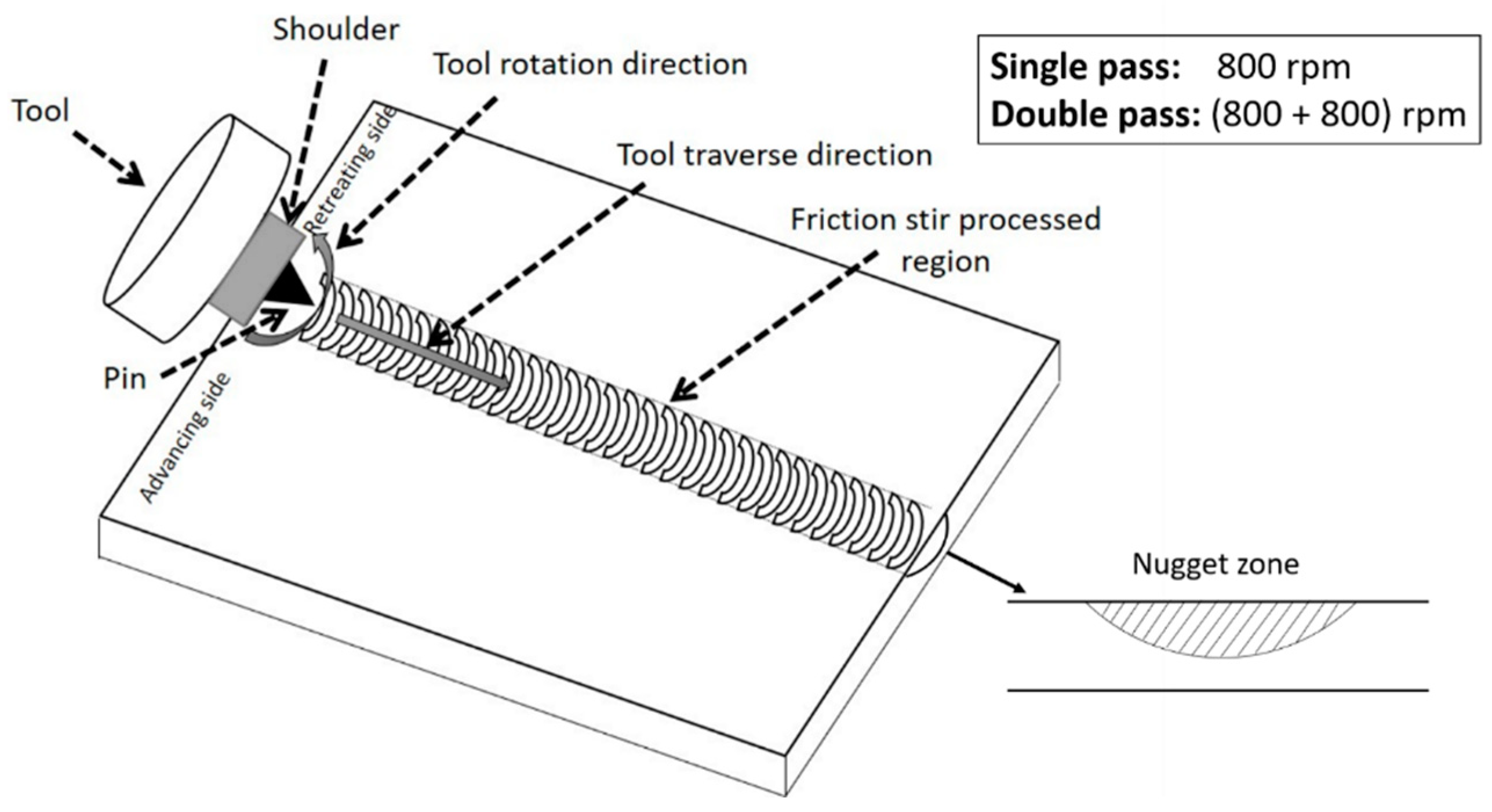
2.2. Friction Stir Processing

A schematic of the friction stir processing is shown in Figure 1. A lanthanated tungsten tool was used during FSP. The details of the parameters used during FSP are provided in Table 1. One-pass FSP was carried out at a tool rotational speed of 800 rpm, whereas two-pass FSP was performed with the second pass, overlapping (100%) the processed region of the first pass and again at a tool rotational speed of 800 rpm. Traverse speed was the same during the one-pass as well as during the two-pass FSP. Figure 2 shows low magnification optical images of the etched one-pass and two-pass FSP samples, with the nugget and thermomechanical heat affected zones indicated.

2.3. Micro Tensile Test

Micro tensile testing was performed on an EFT-5EDC UTM, manufactured by Jinan Testing equipment IE corporation (Jinan, China), capable of exerting a maximum load of 5 kN. Dog-bone tensile test specimens were prepared from the nugget zones of the one-pass and the two-pass FSPed material and from the annealed material. Mini tensile specimens were prepared with a gauge length, width, and thickness of 5 mm, 2 mm, and 1.7 mm, respectively. Samples were subjected to an initial strain rate of 10−3 s−1. To check the reproducibility, three samples were tested from each of the three materials, viz., annealed, one-pass and two-pass materials.

2.4. Microstructural Characterization

The annealed sample and samples from the nugget zone of the FSPed regions, were polished and etched with nital solution. Microstructures were examined using a Carl Zeiss-make optical microscope (Jena, Germany) equipped with a BIOVIS MP 2000 image analyzer. X-ray Diffraction (XRD) studies were performed on a Bruker-make diffractometer (Billerica, MA, USA), using CuKα incident radiation. Electron Backscatter Diffraction (EBSD) studies were performed using a Zeiss Gemini 300 SEM equipped with an Oxford-make EBSD detector (Abingdon, UK) and TSL OIM software. Transmission Electron Microscopy (TEM) studies were performed on a Thermo Scientific (Waltham, MA, USA), Themis 300 G3 instrument, equipped with Velox software.

3. Results and Discussion

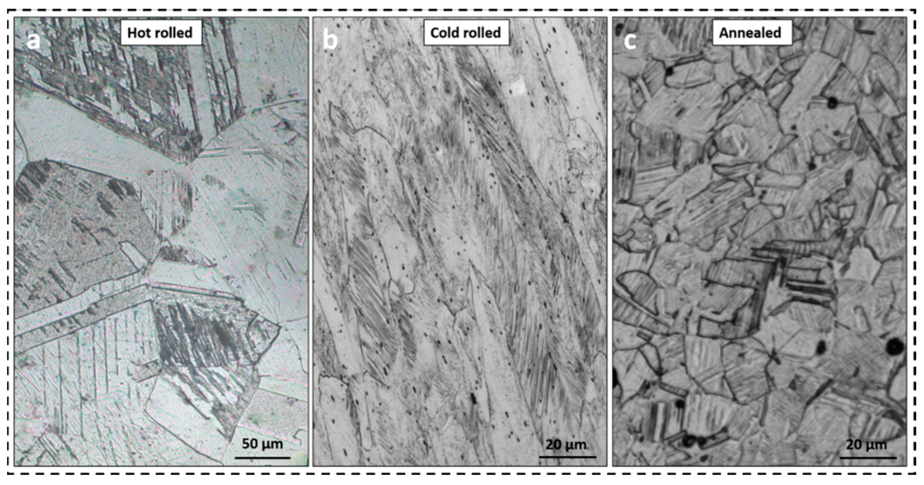
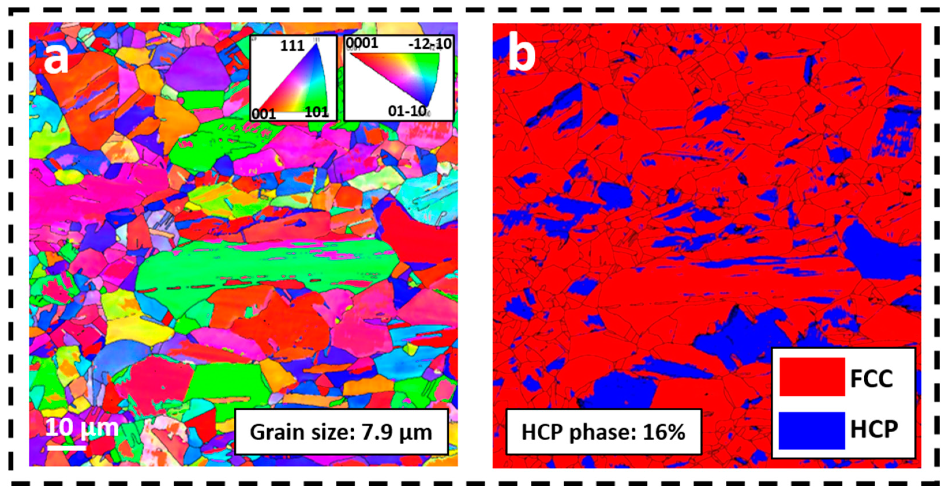
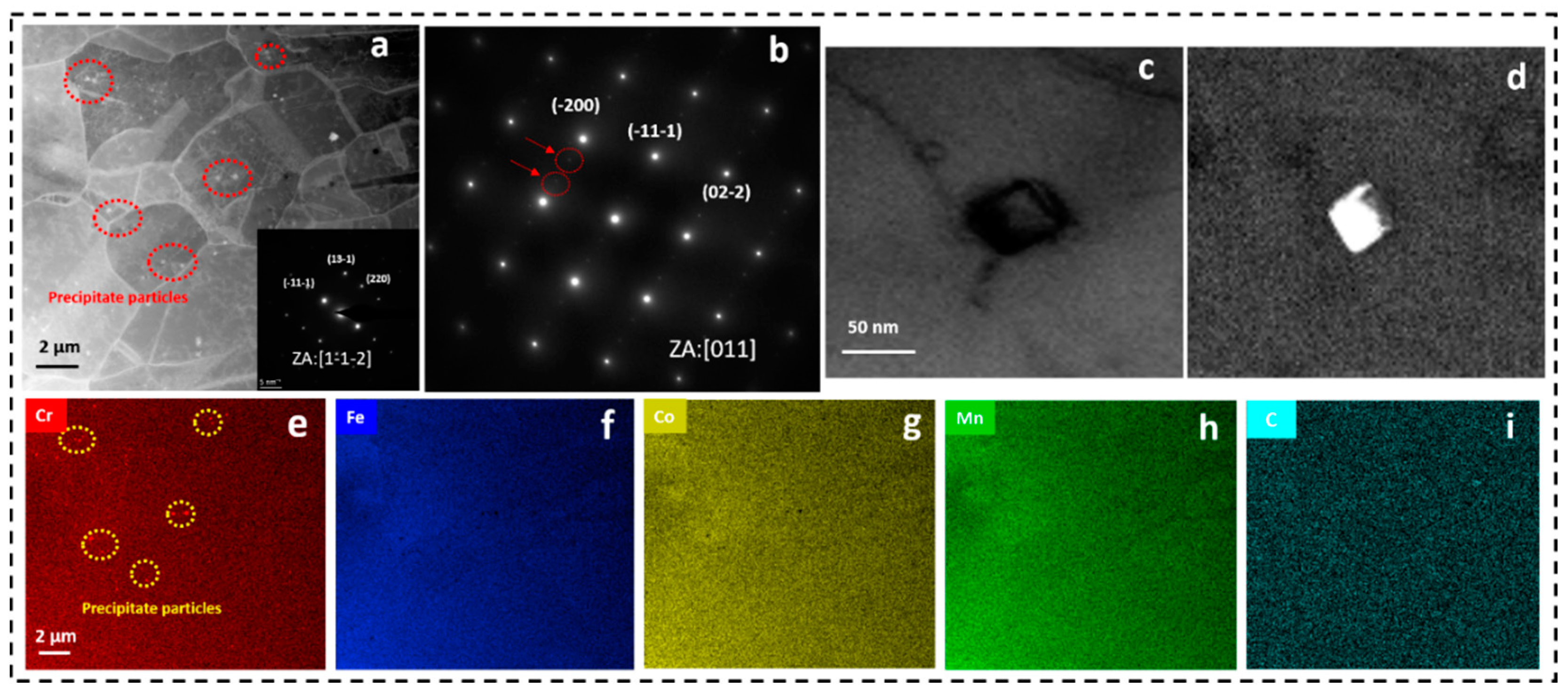
3.1. Composition and Microstructure of the Cold-Rolled and Annealed Sample

An Inductively Coupled Plasma—Atomic Emission Spectrometer (ICP/AES) was used to determine the composition of the alloy. Table 2 provides the weight and atomic percentages of the different elements present in the alloy.
The optical micrographs taken from hot-rolled, cold-rolled, and cold-rolled and annealed sample are shown in Figure 3. As seen in Figure 3a, the microstructure of hot-rolled samples consists of large equiaxed grains. Inside the large equiaxed grains, twins can be clearly seen extending through the grains. The microstructure of the cold-rolled sample, shown in Figure 3b, consisted of pancake shaped grains displaying shear bands across the grains. Figure 3c shows the microstructure of the sample subjected to annealing after cold rolling. The microstructure consisted of small equiaxed recrystallized grains. The twins present inside the small, recrystallized grains could be clearly observed.
The EBSD Inverse Pole Figure (IPF) map of the cold-rolled and annealed sample is shown in Figure 4a. The micrograph displays random orientation of the grains confirming absence of preferred orientation in the sample. Figure 4b shows the EBSD phase map of the cold-rolled and annealed sample. The dual-phase microstructure consisted of FCC and HCP phases. The matrix grain size in the present work was determined by considering the whole matrix grain, including the HCP laminate phase. The grain size was found to be 7.9 ± 2.1 μm. From EBSD phase analysis, the amount of HCP phase in the microstructure was determined to be 16%. Li et al. [23] have described the microstructure in a quaternary Fe50Mn30Co10Cr10 alloy. They have also reported a dual-phase microstructure consisting of compositionally identical FCC and HCP phases, with the HCP phase exhibiting a laminate morphology.
Figure 5a shows a scanning transmission electron microscopy–high angle annular dark field (STEM-HAADF) image of the sample taken in a <112> zone axis orientation. The TEM micrograph also reveals the presence of fine precipitates in the microstructure. The selected area electron diffraction (SAED) pattern shown in Figure 5b, taken from the matrix region containing the precipitate particles, reveals the presence of strong matrix reflections and faint particle reflections. Li et al. [5] have also investigated the microstructure in a TEM and identified the particles to be those of M23C6 carbides. Carbide particles shown in Figure 5a, were found to be precipitated at the grain boundaries and found distributed homogeneously throughout the matrix. The average size of the carbide particles was estimated to be 10–20 nm. The crystallographic orientation relationship between the matrix and the particle was found to be cube-on-cube, usually expressed as <100>matrix//<100>precipitate or {100}matrix//{100}precipitate. This is in agreement with the result reported by Li et al. [2]. The nanosized carbide particles in the matrix provide additional precipitation hardening to the alloy through the Zener pinning effect [24]. Figure 5c,d are the bright field and dark field images of the precipitates whereas, Figure 5e is the STEM-EDS elemental map of Cr, recorded in the same location as shown in Figure 5a. The map clearly reveals the presence of Cr precipitates in the alloy matrix. EDS elemental maps shown in Figure 5f–i indicate uniform distribution of Fe, Co, Mn, and C in the matrix, showing no elemental segregation at the grain level.

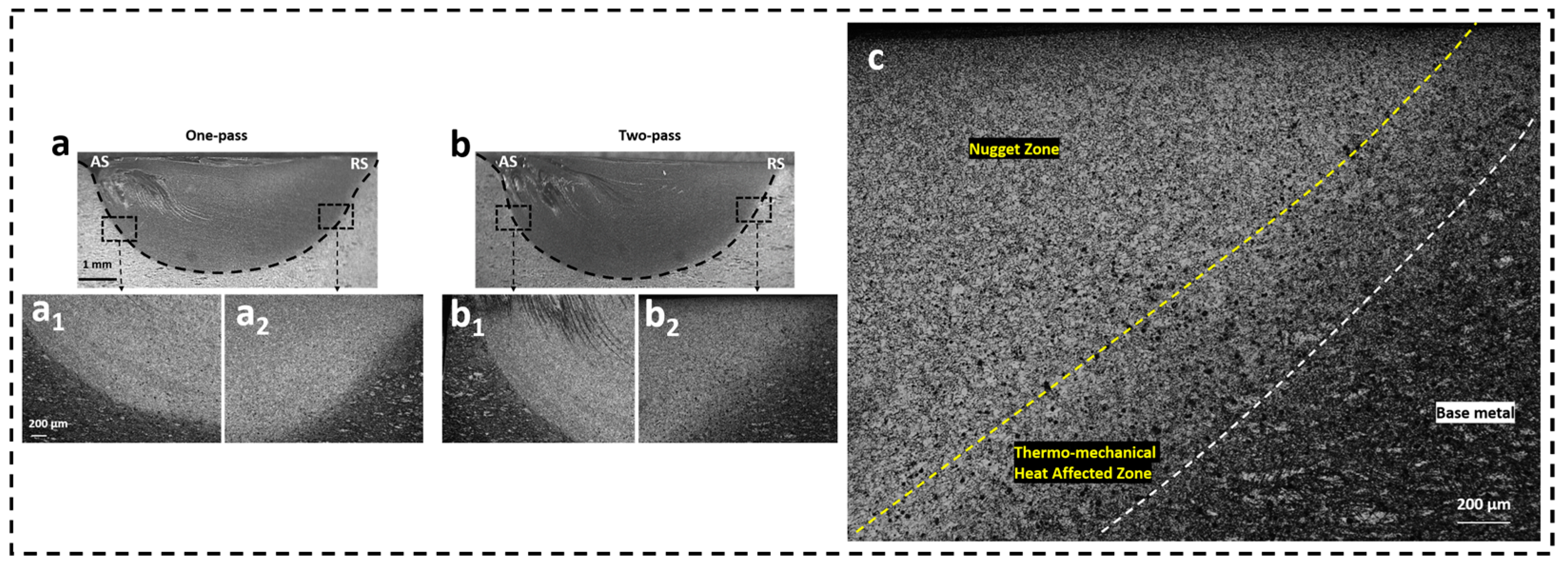
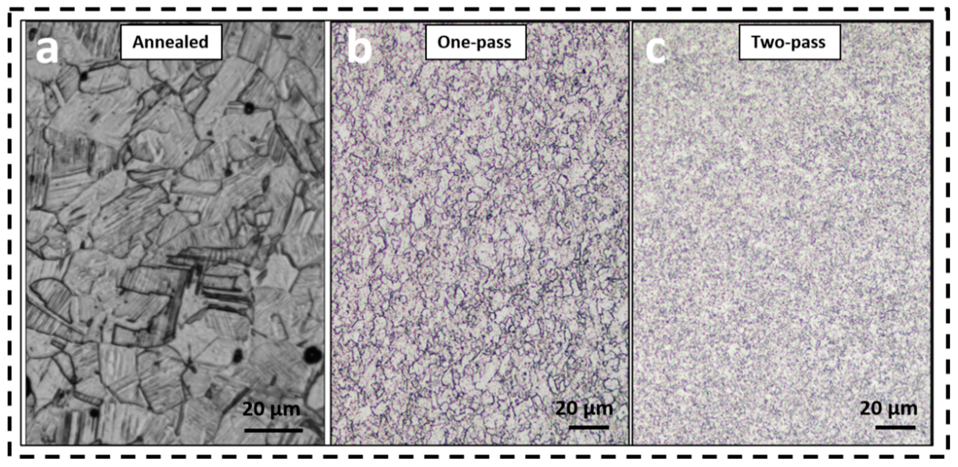
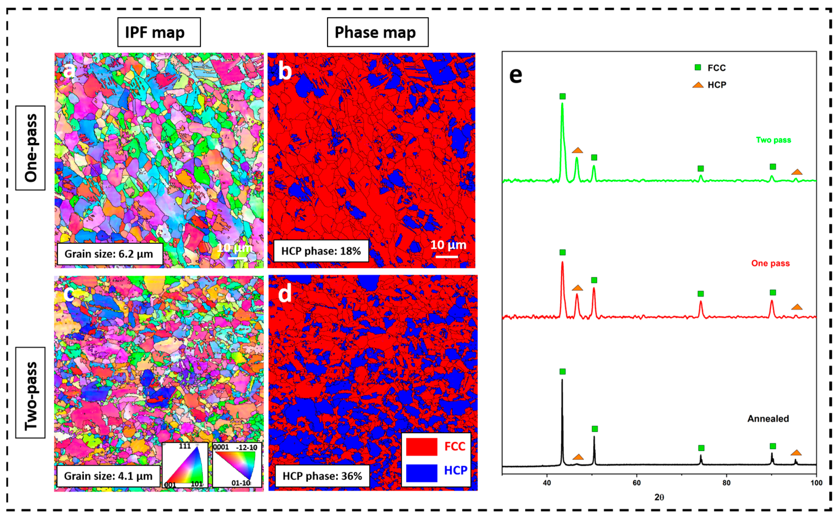
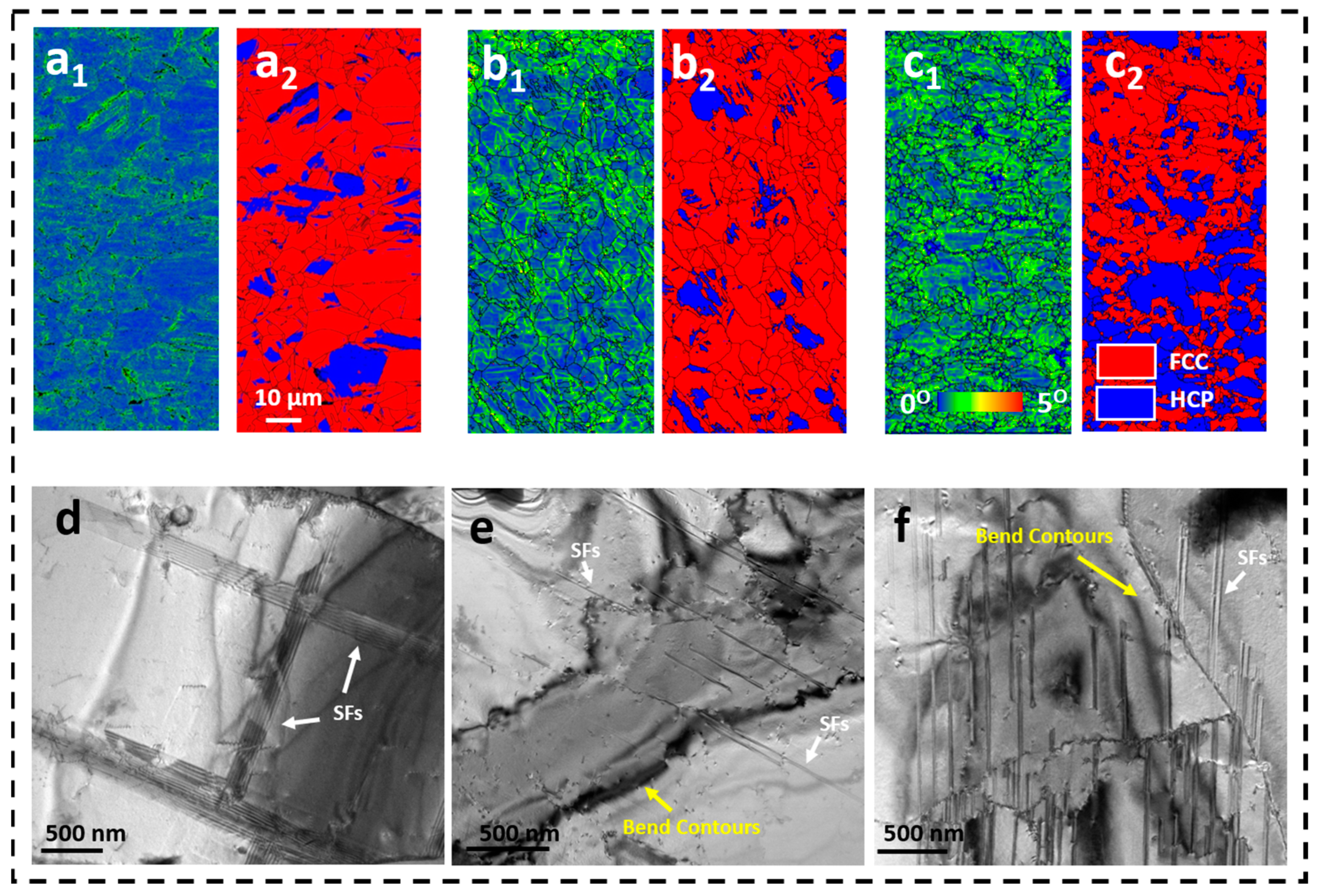
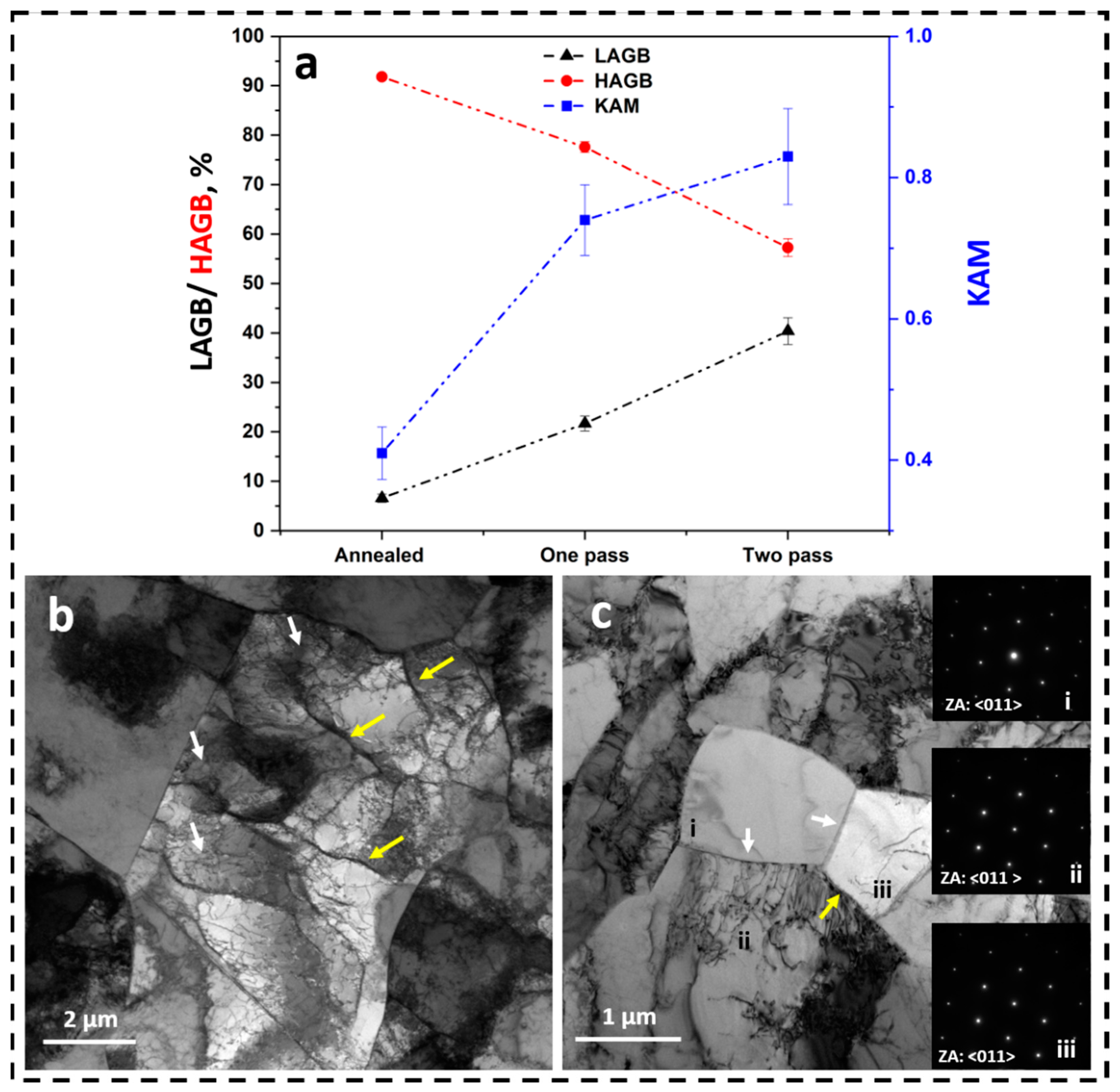
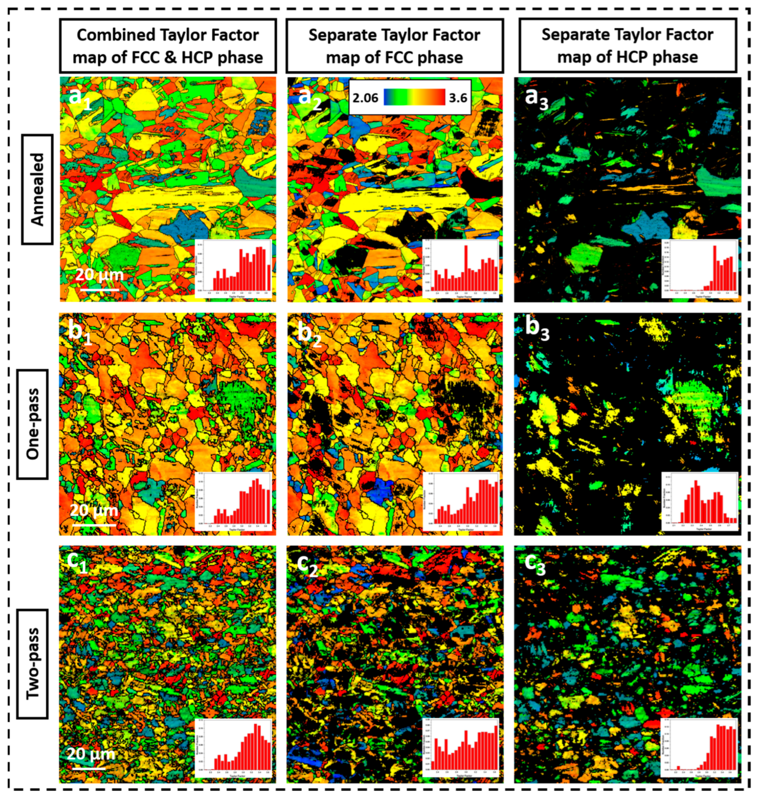
3.2. Friction Stir Processed Samples: Microstructural Evolution

Figure 6 shows the optical micrographs taken from the annealed, nugget zone of one-pass FSP and two-pass FSP samples. The microstructures of FSPed samples consist of very fine grains. Clearly, one-pass FSP reduces the grain size substantially while the subsequent second pass further reduces the grain size of material only marginally. The frictional forces acting between the rotating tool and the work piece, leads to heat generation and along with the severe plastic deformation during FSP, produces a fine-grain microstructure. The more intense the plastic deformation, the more the driving force for dynamic recrystallization in the material.
Figure 7a,c show the IPF images of the one-pass and two-pass FSPed samples. The grain sizes were determined to be 6.2 ± 1.9 μm and 4.1 ± 1.2 μm for one-pass and two-pass FSP samples, respectively. Multi-pass FSP is adopted with the objective of producing a very fine grain size material [25,26]. However, the reduction in grain size obtained after the second pass is not as significant as the one obtained in the first pass FSP. Luo et al. [21] have also reported similar results with no drastic grain refinement observed after second overlapped pass. The inability of the multi-pass FSP to achieve significant grain refinement with constant processing parameters, has been attributed to the accumulated heat in subsequent passes [21,27]. The heat generated and strain rate, along with strain, are known to have a counteracting effect on the evolution of grain size [28,29]. Figure 7b,d show the EBSD phase maps obtained from one-pass and two-pass FSPed samples. It can be observed that the HCP phase in the microstructure increases from 16% in cold-rolled and annealed samples to 18% and 36% in one-pass and two-pass FSPed samples, respectively. During one-pass FSP, only a small volume fraction of FCC phase transforms into HCP phase, whereas, during the second pass, substantial amount of FCC phase transforms into HCP phase, suggesting increased metastability of FCC phase during the second pass. It is known from literature that interstitial atoms hinder the movement of partial dislocations, thereby, increasing the stacking fault energy of the HEA and suppressing the FCC-to-HCP displacive transformation [30]. However, during the second pass of the FSP, the severe plastic deformation enables the alloy to achieve very high strains. In the local regions where the plastic strain is high, the interaction of dislocations in the confined volume results in formation of shear bands. These shear bands act as HCP nucleation sites and promote HCP phase formation. This explains how the significantly increased inhomogeneous stress distribution during the second pass aggravates the strain localization resulting in more HCP phase formation during the second pass than during the first pass in a two-pass FSP process [30]. The X-ray Diffractograms from annealed, one-pass and two-pass FSP samples, shown in Figure 7e, further confirm the changes in HCP phase fraction after FSP. In the annealed condition before FSP, low intensity peaks of HCP phase are observed, whereas, after performing FSP, sharp HCP peaks are seen indicating modification in the phase fractions.
Figure 8(a1,b1,c1) shows Kernal Average Misorientation (KAM) maps of annealed, one-pass and two-pass FSPed samples, respectively. The KAM maps reflect the local mis-orientation experienced by the grains after deformation. The local misorientation is a result of strain mismatch between the different grains and different phases present in the microstructure [29,31]. The strain mismatch is accommodated by geometrically necessary dislocations (GNDs) and the significance of KAM values lies in the fact that it is indicative of the density of the GNDs present in the microstructure. The KAM map of the annealed sample shown in Figure 8(a1) exhibits mostly blue colour indicating almost strain-free microstructure, whereas the KAM maps of one-pass and two-pass FSPed samples exhibit increasing amount of green colour indicating moderate strain distribution across the microstructure. The area fraction of these moderately deformed regions in the microstructure is determined using ImageJ software and were found to be 6.38%, 21.1%, and 33.39% in the annealed, one-pass, and two-pass FSPed samples, respectively. Interestingly, comparison of the KAM maps with the phase maps shown in Figure 8(a2,b2,c2) indicate that during FSP, the HCP phase deforms and attains similar strain accommodation as the FCC phase. Nene et al. [17] have also observed a homogenous KAM pattern in the FSP processed samples of composition Fe50Mn30Co10Cr10, having an initial grain size of 5.2 μm. Liu et al. [15] have also reported that the higher metastability in Fe40Mn20Co20Cr15Si5 alloy causes HCP phase to deform and accommodate strain levels similar to that of the FCC phase. Figure 8d–f shows the presence of SFs in annealed, one-pass and two-pass FSPed samples. In FCC materials, SFs are formed by dissociation of a perfect dislocation into Shockley partials. Gliding of 1/6<112> partial leads to formation of HCP stacking fault. A small number of SFs were present in the annealed sample prior to deformation. Upon processing, and with increasing strain, those SFs overlapped and formed the HCP phase. From Figure 8d–f, it can be observed that the number density of SFs increased upon FSP. In a two-pass FSP sample, the strain induced is larger than that in the one-pass FSP sample. Apart from the strain localization resulting in more HCP phase formation during the second pass, another reason is the increase in number density of overlapping stacking faults.
The combined fraction of High Angle Grain Boundaries (HAGB) and Low Angle Grain Boundaries (LAGB) in FCC and HCP phases, present in the microstructure of annealed, one-pass, and two-pass FSP samples, is shown in Figure 9a. LAGBs are defined as those having a misorientation of 2°–15° whereas HAGBs are those having a misorientation greater than 15°. The results shown in Figure 9a clearly indicate that as the FSP passes increase, the fraction of LAGB increases along with a corresponding drop in the fraction of HAGBs in the microstructure. This has been attributed in the literature to the initial development of Dense Dislocation walls (DDWs) and Dislocation Tangles (DTs) followed by the transformation of DDWs and DTs into LAGBs, with increasing strain [32,33]. The increase in the fraction of LAGBs, with increasing passes during FSP, is also supported by the increasing average KAM values in the one-pass (0.74) and two-pass FSP (0.83) samples, as compared to that in the annealed sample (0.41) (the KAM values determined from the KAM maps shown in Figure 8(a1,b1,c1)). Figure 9b is a bright-field (BF) image taken from a two-pass FSP sample. The BF image shows DDWs and DTs inside the original grain in the microstructure. Figure 9c shows the presence of twin boundaries and low angle boundary in the matrix with same zone axis.
The combined Taylor Factor (TF) maps for FCC and HCP phases present in the microstructure in annealed, one-pass, and two-pass FSP samples are shown in Figure 10(a1), Figure 10(b1), and Figure 10(c1), respectively. The average values of the TF calculated for annealed, one-pass, and two-pass FSP samples are 3.11, 3.16, and 3.14, respectively. The separate TF maps for FCC and HCP phases are also determined and shown in Figure 10. The average values of the TF calculated for FCC phase in annealed, one-pass, and two-pass FSP samples are 3.07, 3.15, and 3.07, respectively, and the same in HCP phase are 3.27, 2.4, and 3.37, respectively. TF maps are indicative of the yield response of the differently oriented grains for a given stress state in the alloy. The higher Taylor factor being indicative of the higher resistance to yielding [34,35]. The grains with least yield resistance are shown in blue colour while the grains with high yield resistance are shown in red colour. It may be noted that the Taylor factor depends on the texture and orientation of the tensile axis, and accounts for averaging of the grain orientations, over all the grains in the sample. For random textures its values are bound between 2.24 and 3.06 [36]. The one-pass FSP sample showed a lower TF value in the HCP phase compared to the annealed and two-pass FSP samples. It could be because of the difference in the orientation of HCP grains. It also indicates that the fraction of the HCP grains resistant to yielding is the least in the microstructure of one-pass material and most in that of two-pass material. As a result, more HCP grains in one-pass FSP will be available for sustaining strains during tensile deformation.

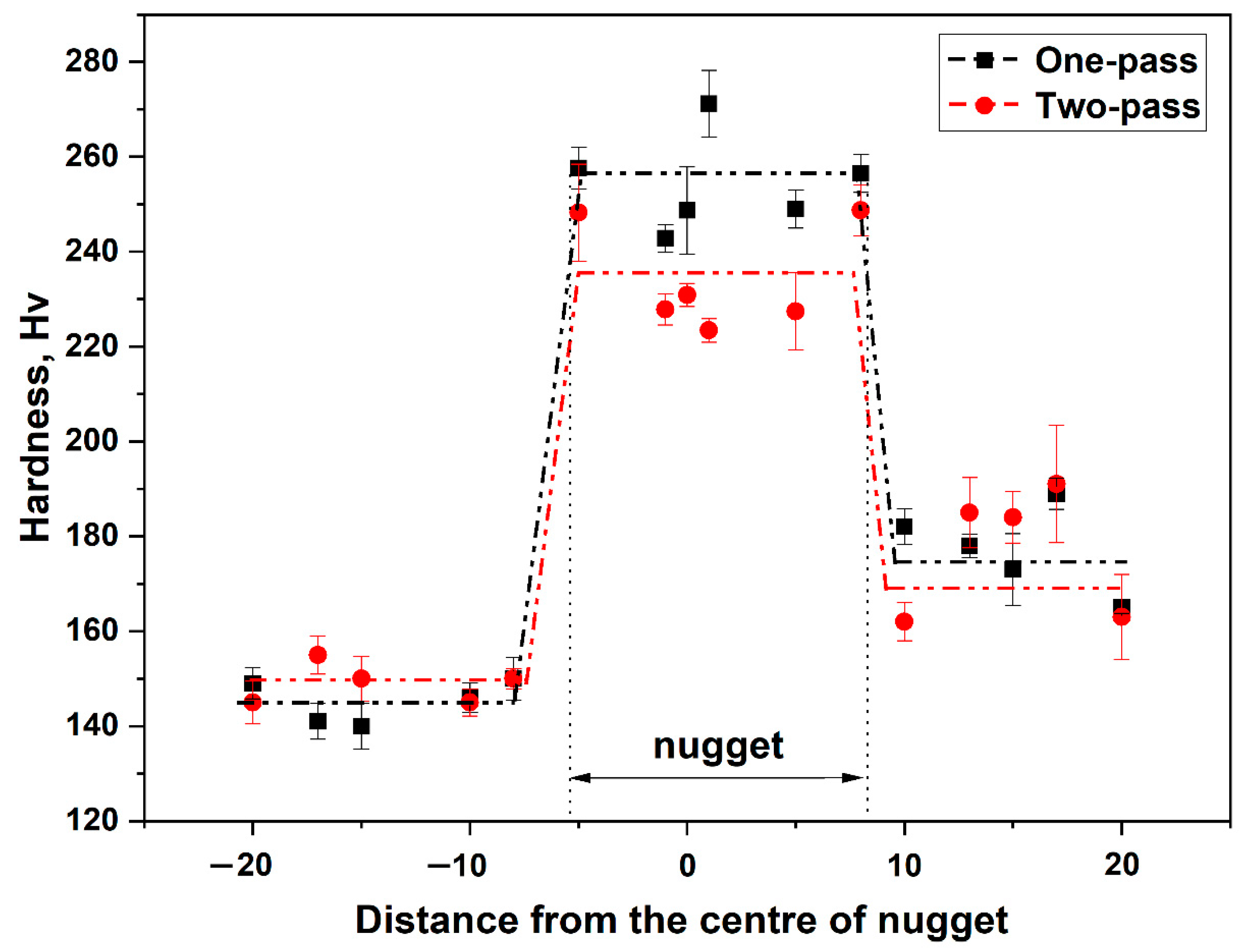
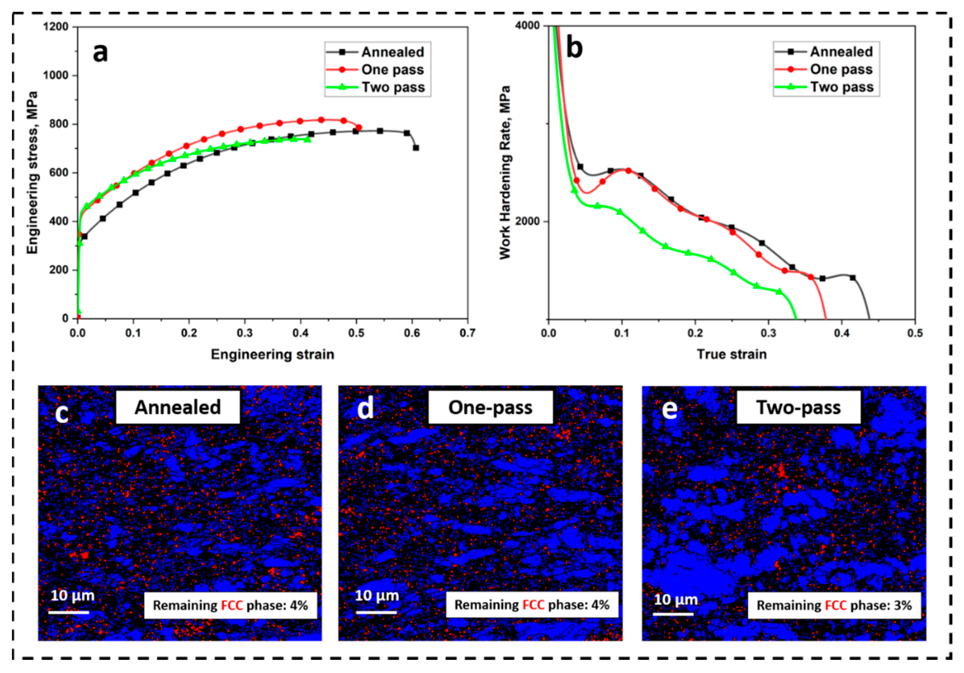
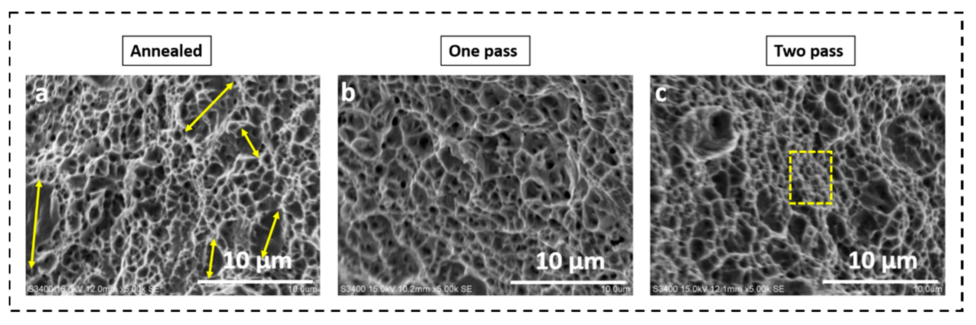
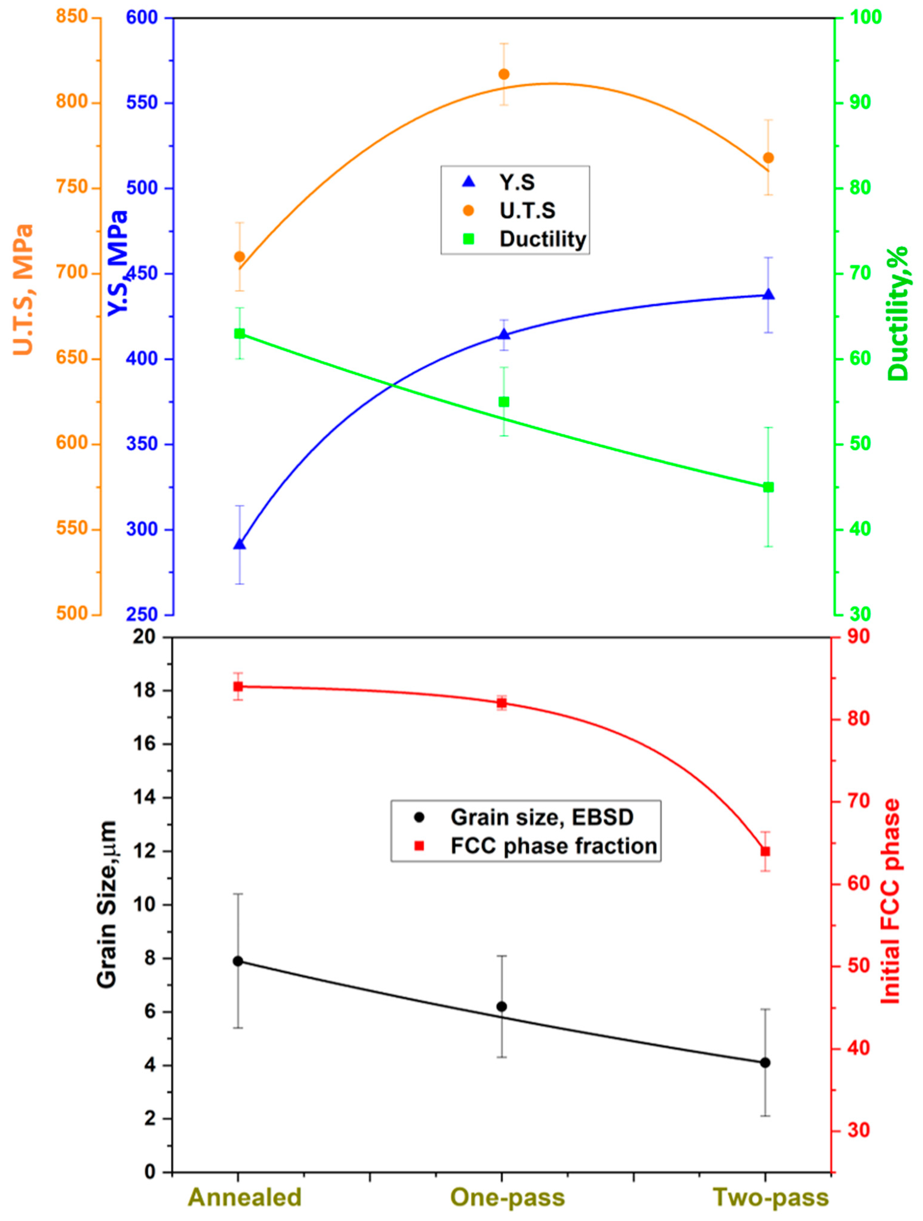
3.3. Friction Stir Processed Samples: Changes in Mechanical Properties

The microhardness profile across the nugget zone of the one-pass and two-pass friction stir processed sample is shown in Figure 11. It is seen that upon FSP, the hardness has increased from 162 HV in the annealed sample to 254 HV and 234 HV in the one-pass and two-pass samples, respectively. The increase in hardness of the material, upon FSP, is a result of grain refinement [10]. Interestingly, the hardness of the one-pass sample is slightly higher than that of the two-pass sample. Although the microstructure of the one-pass sample exhibited a larger grain size than that of the two-pass sample, the volume fraction of FCC phase in the one-pass sample was also higher than that in the two-pass sample. During indentation, strain induced martensitic transformation has been shown to occur beneath the indenter, which accounts for the increase in the hardness measured for the one-pass sample. Sinha et al. [37] have also observed increased hardness of metastable dual-phase high entropy alloys and have also attributed this to strain induced martensitic transformation occurring underneath the nano-indenter.
The engineering stress-strain plot and the work hardening rate vs. true strain plot of the annealed, one-pass, and two-pass FSP samples are shown in Figure 12a and Figure 12b, respectively. Tensile test results obtained at room temperature are summarized in Table 3. It can be seen from Table 3 that the yield strength (YS) increases from a value of 291 MPa for the annealed material to a value of 415 MPa and 437 MPa for the one-pass and two-pass FSP samples, respectively. The increase in the yield strength during FSP is a result of grain refinement occurring during FSP. The grain refinement is attributed to the dynamic recrystallization occurring due to the intense deformation and heat generation during FSP. In addition to the reduction in grain size contributing to Hall-Petch strengthening, the presence of planar defects, such as twins, SFs, low angle boundaries, and interphase boundaries, contribute to the reduction in mean free path of the dislocations, thereby sustaining the strain developed in the matrix resulting in enhanced strengthening [38]. Compared to the annealed material, the one-pass FSP material exhibited higher values of UTS and strain hardening exponent but a lower value of elongation. However, compared to the two-pass FSP material, the one-pass FSP material exhibited higher UTS, higher strain hardening exponent and a higher elongation.
It is evident from the work hardening rate vs true strain plot, shown in Figure 12b, that the annealed material showed high work hardening ability. The work hardening rate was determined to be 2500 MPa and 2000 MPa at a true strain of 0.1 and 0.2, respectively. The increased work hardenability of the annealed material can be ascribed to the metastable FCC dominated microstructure. Upon tensile loading, FCC phase transforms to HCP phase as a result of the TRIP effect. This can also be readily seen from Figure 12c wherein the amount of FCC phase in the microstructure has reduced from 84%, before the tensile loading, to 4%, after complete tensile deformation. Li et al. [5] have also found a high strain hardening in the grain refined alloy of the same composition. The strain hardening rate estimated from their strain-hardening rate vs. true strain plot was around 3000 MPa and 2000 MPa at a true strain of 0.1 and 0.2, respectively. In their work, the amount of FCC phase in the microstructure was reduced from 99.3% before tensile testing to 63.5% in the neck region. Nene et al. [31] have also reported significantly high work hardenability in as-cast metastable Fe42Mn28Co10Cr15Si5 alloy and they too have attributed this to FCC enriched starting microstructure transforming to HCP martensite upon tensile loading because of TRIP.
The two-pass FSP material, on the other hand, exhibits a sharp decrease in the work hardening rate during early stages of tensile deformation. With increasing strain, the work hardening rate decreases less rapidly and exhibits a sustained value until fracture. The rate of work hardening during this stage depends on phase stability of FCC for any given grain size and HCP phase fraction. The dependence on grain size can be explained in terms of the larger grain boundary area exerting more back stress, resulting in a more controlled FCC to HCP transformation and thus, sustained work hardening in very fine grained material [31]. The initial FCC phase fraction in the microstructure before tensile deformation was 64%, and upon complete tensile deformation the phase fraction, reduced to 3% as, shown in Figure 12e. The one-pass FSP material showed a very different work hardening response. After an initial decrease there was a gradual reversal in the slope of the curve at a plastic strain of 0.05, along with a formation of a local maxima. The change in slope of the work hardening curve indicates the TRIP acting in the material. Nene et al. [31] have also observed a similar hump in the work hardening curve in the metastable Fe42Mn28Co10Cr15Si5 alloy which they have ascribed to the dynamic Hall-Petch effect associated with the formation of twins in pre-existing and transformed HCP phases. The larger grain size (6.2 μm) and higher fraction of the FCC phase (82%) in the one-pass FSP material, compared to the two-pass FSP material, optimized the stability of the FCC phase, resulting in increased strain hardening ability.
It is well known that mechanical processing can engender phase transformations in metals. The process of transitioning the FCC structure into HCP structure is a subject of continuing interest. While previous studies indicated that FCC to HCP transition occurs through glide of partial dislocations on alternate close-packed {111} planes, inhomogeneous bending strain would make this dislocation activity unfavorable. Sun et al. [39] performed in-situ TEM investigation to determine the mechanisms operating at the atomic scale during bending of Ag nano-wires. While dislocation glide and deformation twinning are mechanisms of plastic deformation in metals under conventional loading, phase transition becomes an important mechanism to accommodate plastic strain under bending, at least for Ag nano-wires. They have shown that a sequential phase transformation from FCC to BCC to HCP to re-oriented FCC, occurs upon gradual increase in the bending strain, through a process of Bain straining [40]. Grain boundary sliding is known to exert an influence on plastic deformation at ambient temperature and is of considerable interest in research involving plastic deformation in nano-crystalline solids [41]. Wang et al. [42] have performed an in-situ TEM investigation on a general high-angle tilt boundary in FCC Pt bi-crystal and obtained insight into the disconnection mediated grain boundary sliding process. Disconnections are defects that can be characterized by a step height and Burgers vector. They have shown that while pure grain boundary sliding occurs by glide of disconnection along the boundary, the coupled process of GB sliding, and atomic plane transfer occurs through high-applied stress driven displacive atomic events, at ambient temperature. In the presently-studied high entropy alloy system, similar investigations could be carried out in future, on bi-crystals extracted from polycrystals, and carrying out the nanomechanical tests in an aberration corrected atomic resolution TEM. This would enable tracking of atomic scale motion of grain boundaries and obtain insights into mechanisms of GB sliding and deformation behavior of HEA.
The fractographs of the annealed, one-pass, and two-pass FSP tensile test specimens are shown in Figure 13. The fractographs exhibit equiaxed dimples indicating ductile failure in the samples. The dimples and tear ridges observed in the fractographs are a manifestation of nucleation, growth, and coalescence of microvoids. The presence of nanosize carbides in the microstructure could have served as the initiation sites for the microvoids. A closer look at the bottom of the microvoid, however, did not reveal the presence of carbides, indicating that the carbides have debonded from the matrix. It is also clear from the fractographs that the average size and depth of the dimples decrease with decreasing grain size. This is also in agreement with the higher ductility obtained in annealed samples, which is manifested in the fractographs through deep dimples. Naghizadeh and Mirzadeh [43] have also seen that on the fracture surfaces of AISI 304 stainless steel samples, size and depth of dimples increase with increasing average grain size, consistent with the results obtained here.
A plot showing the variation of grain size, initial fraction of FCC in the microstructure, the yield and the tensile strength, and % elongation in the annealed, the one-pass, and the two-pass materials, is shown in Figure 14. It is seen that the tensile strength of the one-pass material is higher than that of the annealed material and it is also higher than that of the two-pass material. This can be understood in terms of two counteracting factors which influence the tensile strength of the material, viz., grain size and the initial fraction of FCC in the material. It has been shown previously by Li et al. [1,23] that the strength-ductility of the HEA, Fe50Mn30Co10Cr10, depends on the grain size and fraction of HCP phase, as well as on the density of the stacking faults. It can be seen that upon decreasing the grain size from annealed to one-pass material, both Y S and UTS increases and the total elongation decreases. This result is consistent with the trend that decreasing grain size leads to increased resistance to deformation [44,45]. Similar grain size effects on YS and UTS were observed in AISI 304 austenitic stainless steel, and the authors have proposed Hall-Petch type equations to relate the YS and UTS to the average grain size [43]. On the other hand, along with a reduction in grain size, there is also a reduction in the fraction of the FCC phase in the microstructures of the annealed, the one-pass, and the two-pass material. The decreased fraction of the FCC in the microstructure results in a lower amount of HCP phase formed though TRIP effect, during subsequent tensile loading, resulting in lower value of UTS. Similar results have been obtained in TRIP-assisted steels, wherein a decrease in the fraction of retained austenite leads to a decrease in the value of UTS [46,47]. Thus, the one-pass FSP sample with an optimum microstructure, consisting of relatively high fraction of FCC phase and a small grain size, attains high work hardening and exhibits good combination of strength and ductility.

4. Conclusions

FSP was performed on a non-equiatomic, dual-phase, metastable HEA, Fe49.5Mn30Co10Cr10C0.5, which upon deformation, exhibits an FCC-to-HCP transformation. The material was subjected to one-pass and two-pass FSP and the nugget zone from different FSPed samples were characterized by its microstructure. The mechanical properties of the FSPed material were compared with that of the annealed material. The following are the conclusions from this work:
  • Friction stir processing significantly reduced the grain size of the material. The samples subjected to one-pass and two-pass FSP showed around 22% and 48% reduction in grain size, respectively.
  • Severe plastic deformation during FSP results in a strain induced FCC-to-HCP transformation. The amount of deformation induced HCP phase in the microstructure increases with an increase in the number of FSP passes.
  • The evolution of the dual-phase microstructure into a fully martensitic microstructure during tensile testing of annealed and FSPed samples indicates strain induced martensitic transformation is the dominant mode for plasticity.
  • Compared to the annealed sample, the samples subjected to one-pass and two-pass FSP showed 90% and 100% increase in yield strength and 12% and 28% decrease in ductility, respectively.
  • One-pass FSPed material exhibits a higher work hardening rate and a higher UTS value, as compared to both annealed and two-pass FSPed material. This is due to a combination of two factors, viz., a small grain size and a large fraction of metastable FCC phase in the microstructure of the one-pass material.

Author Contributions

Conceptualization, N.M., A.G.R. and N.P.; Methodology, A.G.R.; Validation, A.G.R. and N.P.; Formal analysis, N.M.; Investigation, N.M. and S.G.D.; Resources, A.G.R., S.G.D. and N.P.; Data curation, N.M.; Writing—original draft, N.M.; Writing—review & editing, A.G.R. and N.P.; Visualization, A.G.R. and N.P.; Supervision, A.G.R. and N.P. All authors have read and agreed to the published version of the manuscript.

Funding

This research received no external funding.

Data Availability Statement

The data presented in this study are available on request from the corresponding author.

Conflicts of Interest

The authors declare no conflict of interest.

References

  1. Li, Z.; Pradeep, K.G.; Deng, Y.; Raabe, D.; Tasan, C.C. Metastable high-entropy dual-phase alloys overcome the strength-ductility trade-off. Nature 2016, 534, 227–230. [Google Scholar] [CrossRef] [PubMed]
  2. Miracle, D.; Majumdar, B.; Wertz, K.; Gorsse, S. New strategies and tests to accelerate discovery and development of multi-principal element structural alloys. Scr. Mater. 2017, 127, 195–200. [Google Scholar] [CrossRef]
  3. Yeh, J.-W.; Chen, S.K.; Lin, S.-J.; Gan, J.-Y.; Chin, T.-S.; Shun, T.-T.; Tsau, C.-H.; Chang, S.-Y. Nanostructured High-Entropy Alloys with Multiple Principal Elements: Novel Alloy Design Concepts and Outcomes. Adv. Eng. Mater. 2004, 6, 299–303. [Google Scholar] [CrossRef]
  4. Li, Z.; Raabe, D. Strong and Ductile Non-equiatomic High-Entropy Alloys: Design, Processing, Microstructure, and Mechanical Properties. JOM 2017, 69, 2099–2106. [Google Scholar] [CrossRef] [PubMed] [Green Version]
  5. Li, Z.; Tasan, C.C.; Springer, H.; Gault, B.; Raabe, D. Interstitial atoms enable joint twinning and transformation induced plasticity in strong and ductile high-entropy alloys. Sci. Rep. 2017, 7, 40704. [Google Scholar] [CrossRef] [PubMed] [Green Version]
  6. Shaysultanov, D.; Raimov, K.; Stepanov, N.; Zherebtsov, S. Friction Stir Welding of a TRIP Fe49Mn3Crr10Co10C1 High Entropy Alloy. Metals 2021, 11, 66. [Google Scholar] [CrossRef]
  7. Nene, S.; Frank, M.; Liu, K.; Sinha, S.; Mishra, R.; McWilliams, B.; Cho, K. Reversed strength-ductility relationship in microstructurally flexible high entropy alloy. Scr. Mater. 2018, 154, 163–167. [Google Scholar] [CrossRef]
  8. Chen, Y.C.; Fujii, H.; Tsumura, T.; Kitagawa, Y.; Nakata, K.; Ikeuchi, K.; Matsubayashi, K.; Michishita, Y.; Fujiya, Y.; Katoh, J. Friction stir processing of 316L stainless steel plate. Sci. Technol. Weld. Join. 2009, 14, 197–201. [Google Scholar] [CrossRef]
  9. Rao, A.G.; Ravi, K.R.; Ramakrishnarao, B.; Deshmukh, V.P.; Sharma, A.; Prabhu, N.; Kashyap, B.P. Recrystallization phenomena during friction stir processing of hypereutectic aluminum-silicon alloy. Metall. Mater. Trans. A Phys. Metall. Mater. Sci. 2013, 44, 1519–1529. [Google Scholar] [CrossRef]
  10. Mishra, M.K.; Gunasekaran, G.; Rao, A.G.; Kashyap, B.P.; Prabhu, N. Effect of Multipass Friction Stir Processing on Mechanical and Corrosion Behavior of 2507 Super Duplex Stainless Steel. J. Mater. Eng. Perform. 2017, 26, 849–860. [Google Scholar] [CrossRef]
  11. Kumar, N.; Komarasamy, M.; Nelaturu, P.; Tang, Z.; Liaw, P.K.; Mishra, R.S. Friction Stir Processing of a High Entropy Alloy Al0.1CoCrFeNi. Min. Met. Mater. Soc. 2015, 67, 1007–1013. [Google Scholar] [CrossRef]
  12. Komarasamy, M.; Kumar, N.; Tang, Z.; Mishra, R.; Liaw, P. Effect of microstructure on the deformation mechanism of friction stir-processed Al0.1CoCrFeNi high entropy alloy. Mater. Res. Lett. 2014, 3, 30–34. [Google Scholar] [CrossRef]
  13. Wang, T.; Shukla, S.; Komarasamy, M.; Liu, K.; Mishra, R.S. Towards heterogeneous Al x CoCrFeNi high entropy alloy via friction stir processing. Mater. Lett. 2019, 236, 472–475. [Google Scholar] [CrossRef]
  14. Li, N.; Jia, C.-L.; Wang, Z.-W.; Wu, L.-H.; Ni, D.-R.; Li, Z.-K.; Fu, H.-M.; Xue, P.; Xiao, B.-L.; Ma, Z.-Y.; et al. Achieving a High–Strength CoCrFeNiCu High–Entropy Alloy with an Ultrafine–Grained Structure via Friction Stir Processing. Acta Metall. Sin. Engl. Lett. 2020, 33, 947–956. [Google Scholar] [CrossRef]
  15. Liu, K.; Nene, S.S.; Frank, M.; Mishra, R.S. Effect of Strain Rate on Deformation Response of Metastable High Entropy Alloys Upon Friction Stir Processing. Metall. Mater. Trans. A Phys. Metall. Mater. Sci. 2020, 51, 5043–5048. [Google Scholar] [CrossRef]
  16. Sittiho, A.; Bhattacharyya, M.; Graves, J.; Nene, S.S.; Mishra, R.S.; Charit, I. Friction stir processing of a high entropy alloy Fe42Co10Cr15Mn28Si5 with transformative characteristics: Microstructure and mechanical properties. Mater. Today Commun. 2021, 28, 102635. [Google Scholar] [CrossRef]
  17. Nene, S.S.; Liu, K.; Frank, M.; Mishra, R.S.; Brennan, R.E.; Cho, K.C.; Li, Z.; Raabe, D. Enhanced strength and ductility in a friction stir processing engineered dual phase high entropy alloy. Sci. Rep. 2017, 7, 16167. [Google Scholar] [CrossRef] [PubMed] [Green Version]
  18. Li, Z.; Raabe, D. Influence of compositional inhomogeneity on mechanical behavior of an interstitial dual-phase high-entropy alloy. Mater. Chem. Phys. 2018, 210, 29–36. [Google Scholar] [CrossRef]
  19. Su, J.; Raabe, D.; Li, Z. Hierarchical microstructure design to tune the mechanical behavior of an interstitial TRIP-TWIP high-entropy alloy. Acta Mater. 2018, 163, 40–54. [Google Scholar] [CrossRef]
  20. Muribwathoho, O.; Mabuwa, S.; Msomi, V. Review on Multi-Pass Friction Stir Processing of Aluminium Alloys. Preprint 2020. [Google Scholar] [CrossRef]
  21. Luo, X.; Cao, G.; Zhang, W.; Qiu, C.; Zhang, D. Ductility improvement of an AZ61 magnesium alloy through two-pass submerged friction stir processing. Materials 2017, 10, 253. [Google Scholar] [CrossRef] [PubMed] [Green Version]
  22. Bauri, R.; Yadav, D.; Suhas, G. Effect of friction stir processing (FSP) on microstructure and properties of Al-TiC in situ composite. Mater. Sci. Eng. A 2011, 528, 4732–4739. [Google Scholar] [CrossRef]
  23. Li, Z.; Tasan, C.C.; Pradeep, K.G.; Raabe, D. A TRIP-assisted dual-phase high-entropy alloy: Grain size and phase fraction effects on deformation behavior. Acta Mater. 2017, 131, 323–335. [Google Scholar] [CrossRef]
  24. Hu, G.; Zeng, L.; Du, H.; Wang, Q.; Fan, Z.; Liu, X. Combined effects of solute drag and Zener pinning on grain growth of a NiCoCr medium-entropy alloy. Intermetallics 2021, 136, 107271. [Google Scholar] [CrossRef]
  25. Liu, K.; Nene, S.S.; Frank, M.; Sinha, S.; Mishra, R.S. Metastability-assisted fatigue behavior in a friction stir processed dual-phase high entropy alloy. Mater. Res. Lett. 2018, 6, 613–619. [Google Scholar] [CrossRef] [Green Version]
  26. Moustafa, E. Effect of multi-pass friction stir processing on mechanical properties for AA2024/Al2O3 nanocomposites. Materials 2017, 10, 1053. [Google Scholar] [CrossRef] [Green Version]
  27. El-Rayes, M.M.; El-Danaf, E.A. The influence of multi-pass friction stir processing on the microstructural and mechanical properties of Aluminum Alloy 6082. J. Mater. Process. Technol. 2012, 212, 1157–1168. [Google Scholar] [CrossRef]
  28. Mishra, M.; Rao, A.; Balasundar, I.; Kashyap, B.; Prabhu, N. On the microstructure evolution in friction stir processed 2507 super duplex stainless steel and its effect on tensile behaviour at ambient and elevated temperatures. Mater. Sci. Eng. A 2018, 719, 82–92. [Google Scholar] [CrossRef]
  29. Xue, P.; Wang, B.; An, X.; Ni, D.; Xiao, B.; Ma, Z. Improved cyclic softening behavior of ultrafine-grained Cu with high microstructural stability. Scr. Mater. 2019, 166, 10–14. [Google Scholar] [CrossRef]
  30. Zhu, S.; Yan, D.; Gan, K.; Lu, W.; Li, Z. Awakening the metastability of an interstitial high entropy alloy via severe deformation. Scr. Mater. 2021, 191, 96–100. [Google Scholar] [CrossRef]
  31. Nene, S.S.; Frank, M.; Liu, K.; Mishra, R.S.; McWilliams, B.A.; Cho, K.C. Extremely high strength and work hardening ability in a metastable high entropy alloy. Sci. Rep. 2018, 8, 9920. [Google Scholar] [CrossRef] [PubMed] [Green Version]
  32. Muñoz, J.A.; Bolmaro, R.E.; Jorge, A.M.; Zhilyaev, A.; Cabrera, J.M. Prediction of Generation of High- and Low-Angle Grain Boundaries (HAGB and LAGB) During Severe Plastic Deformation. Metall. Mater. Trans. A Phys. Metall. Mater. Sci. 2020, 51, 4674–4684. [Google Scholar] [CrossRef]
  33. Azadmanjiri, J.; Berndt, C.C.; Kapoor, A.; Wen, C. Development of Surface Nano-Crystallization in Alloys by Surface Mechanical Attrition Treatment (SMAT). Crit. Rev. Solid State Mater. Sci. 2015, 40, 164–181. [Google Scholar] [CrossRef]
  34. Starink, M.; Wang, S. A model for the yield strength of overaged Al-Zn-Mg-Cu alloys. Acta Mater. 2003, 51, 5131–5150. [Google Scholar] [CrossRef] [Green Version]
  35. Electron Backscatter Diffraction (EBSD) Analysis of Cracking in Polycrystalline Materials. Technical Note. AMETEK Mater. Anal. Div. 2015, pp. 85–90. Available online: https://www.academia.edu/41845100/Electron_Backscatter_Diffraction_in_Materials_Science_Second_Edition (accessed on 25 November 2022).
  36. Huo, S.H.; Qian, M.; Schaffer, G.B.; Crossin, E. Fundamentals of Aluminium Metallurgy: Production, Processing and Applications; Springer: Berlin/Heidelberg, Germany, 2011. [Google Scholar]
  37. Sinha, S.; Mirshams, R.A.; Wang, T.; Nene, S.S.; Frank, M.; Liu, K.; Mishra, R.S. Nanoindentation behavior of high entropy alloys with transformation-induced plasticity. Sci. Rep. 2019, 9, 6639. [Google Scholar] [CrossRef] [Green Version]
  38. He, Z.; Jia, N.; Ma, D.; Yan, H.; Li, Z.; Raabe, D. Joint contribution of transformation and twinning to the high strength-ductility combination of a FeMnCoCr high entropy alloy at cryogenic temperatures. Mater. Sci. Eng. A 2019, 759, 437–447. [Google Scholar] [CrossRef]
  39. Sun, S.; Li, D.; Yang, C.; Fu, L.; Kong, D.; Lu, Y.; Guo, Y.; Liu, D.; Guan, P.; Zhang, Z.; et al. Direct Atomic-Scale Observation of Ultrasmall Ag Nanowires that Exhibit fcc, bcc, and hcp Structures under Bending. Phys. Rev. Lett. 2022, 128, 015701. [Google Scholar] [CrossRef]
  40. Bain, E.C. The Nature of Martensite. Trans. AIME 1924, 70, 25–35. [Google Scholar]
  41. Han, J.; Thomas, S.L.; Srolovitz, D.J. Grain-boundary kinetics: A unified approach. Prog. Mater. Sci. 2018, 98, 386–476. [Google Scholar] [CrossRef] [Green Version]
  42. Wang, L.; Zhang, Y.; Zeng, Z.; Zhou, H.; He, J.; Liu, P.; Chen, M.; Han, J.; Srolovitz, D.J.; Teng, J.; et al. Tracking the sliding of grain boundaries at the atomic scale. Science 2022, 375, 1261–1265. [Google Scholar] [CrossRef]
  43. NaghiZadeh, M.; Mirzadeh, H. Effects of Grain Size on Mechanical Properties and Work-Hardening Behavior of AISI 304 Austenitic Stainless Steel. Steel Res. Int. 2019, 90, 1–9. [Google Scholar] [CrossRef]
  44. Zehetbauer, M.J.; Zhu, Y.T. (Eds.) Bulk Nanostructured Materials; Wiley: Hoboken, NJ, USA, 2009. [Google Scholar]
  45. Dieter, G.E.; Bacon, D. Mechanical Metallurgy; McGraw-Hill: New York, NY, USA, 1988. [Google Scholar]
  46. Shen, Y.; Qiu, L.; Sun, X.; Zuo, L.; Liaw, P.; Raabe, D. Effects of retained austenite volume fraction, morphology, and carbon content on strength and ductility of nanostructured TRIP-assisted steels. Mater. Sci. Eng. A 2015, 636, 551–564. [Google Scholar] [CrossRef] [Green Version]
  47. Chiang, J.; Lawrence, B.; Boyd, J.; Pilkey, A. Effect of microstructure on retained austenite stability and work hardening of TRIP steels. Mater. Sci. Eng. A 2011, 528, 4516–4521. [Google Scholar] [CrossRef]
Figure 1. Schematic of friction stir processing.
Lubricants 11 00002 g001
Figure 2. Optical micrographs showing thermo-mechanically processed zone in (a) one-pass and (b) two-pass FSPed samples. (a1,b1) show the microstructure at the advancing side while (a2,b2) show the microstructure on the retreating side. (c) is a magnified image of (b2) showing distinct regions of nugget and thermomechanical heat affected zone.
Lubricants 11 00002 g002
Figure 3. Optical micrographs showing the microstructures of the (a) hot-rolled, (b) cold-rolled and (c) cold-rolled and annealed sample.
Lubricants 11 00002 g003
Figure 4. EBSD (a) IPF map and (b) phase map of the cold-rolled and annealed sample.
Lubricants 11 00002 g004
Figure 5. (a) STEM-HAADF image of annealed sample. The precipitates present in the matrix are encircled in red color (b) SAED pattern showing strong matrix reflections and faint precipitate reflections, TEM (c) bright field image, (d) dark field image of precipitate and elemental maps of (e) Cr (chromium carbide precipitates encircled in yellow) (f) Fe, (g) Co, (h) Mn and (i) C.
Lubricants 11 00002 g005
Figure 6. Optical micrographs showing the microstructure of the (a) annealed, (b) one-pass and (c) two-pass FSP samples.
Lubricants 11 00002 g006
Figure 7. EBSD (a,c) IPF maps and (b,d) phase maps of one-pass and two-pass FSP samples. (e) X-ray diffractograms of annealed, one-pass and two-pass FSP samples.
Lubricants 11 00002 g007
Figure 8. EBSD KAM maps of (a1) annealed, (b1) one-pass and (c1) two-pass FSP samples and phase maps of (a2) annealed, (b2) one-pass and (c2) two-pass FSP samples TEM micrographs showing presence of stacking faults in the (d) annealed, (e) one-pass, and (f) two-pass FSP samples.
Lubricants 11 00002 g008
Figure 9. (a) Evolution of grain boundary fraction (LAGB/HAGB) and KAM value in the microstructure of the alloy during FSP. (b) TEM bright-field micrograph showing a network of high dislocation density (white arrows) and dislocation walls (yellow arrows) in the microstructure of a two-pass FSP sample, and (c) TEM bright-field micrograph showing twin boundaries (white arrows) and low angle grain boundary (yellow arrows) in the microstructure of a two-pass FSP sample. The insets show the diffraction patterns taken from three different regions in the microstructure.
Lubricants 11 00002 g009
Figure 10. Taylor factor maps of (a1a3) annealed, (b1b3) one-pass and (c1c3) two-pass FSP samples.
Lubricants 11 00002 g010
Figure 11. Hardness distribution across the nugget zone of the one-pass and two-pass FSP samples.
Lubricants 11 00002 g011
Figure 12. (a) Tensile stress-strain plot, (b) Work hardening plot and EBSD phase maps taken from the region close to the fracture surface of (c) annealed, (d) one-pass FSP, and (e) two-pass FSP samples.
Lubricants 11 00002 g012
Figure 13. The dimpled fracture surface of (a) annealed, (b) one-pass and (c) two-pass FSP sample.
Lubricants 11 00002 g013
Figure 14. Variation in the grain size, FCC phase fraction in the microstructure and the values of Y.S., U.T.S. and % elongation of annealed, one-pass and two-pass FSP samples.
Lubricants 11 00002 g014
Table 1. Friction Stir Processing parameters.
Tool materialW-La2O3
Plate thickness5 mm
Tool rotation speed800 rpm
Tool traverse speed50 mm/min
Shoulder dia.22 mm
Pin dia.14 mm
Pin length4 mm
Table 2. Chemical composition of the alloy.
FeMnCoCrC
Wt.%49 ± 0.9430 ± 0.809 ± 0.2810 ± 0.640.11 ± 0
At.%48 ± 0.9330 ± 0.459 ± 0.4710 ± 0.670.51 ± 0
Table 3. Mechanical properties obtained from tensile test conducted on an annealed, one-pass, and two-pass FSP samples.
Yield Strength, MPaUltimate Tensile Strength, MPaElongation, %Strain-Hardening Exponent, n
Annealed 291 ± 23710 ± 3063% ± 30.36
One-pass415 ± 9818 ± 1855% ± 40.38
Two-pass437 ± 21768 ± 2145% ± 70.31
Disclaimer/Publisher’s Note: The statements, opinions and data contained in all publications are solely those of the individual author(s) and contributor(s) and not of MDPI and/or the editor(s). MDPI and/or the editor(s) disclaim responsibility for any injury to people or property resulting from any ideas, methods, instructions or products referred to in the content.

