Article

Thermo-Mechanical Modelling of Friction Stir Processing of AZ91 Alloy: Using Smoothed-Particle Hydrodynamics

by
Roshan Vijay Marode
,
Srinivasa Rao Pedapati
*,
Tamiru Alemu Lemma
and
Venkata Somi Reddy Janga
Department of Mechanical Engineering, Universiti Teknologi PETRONAS, Seri Iskandar 32610, Malaysia
*
Author to whom correspondence should be addressed.
Lubricants 2022, 10(12), 355; https://doi.org/10.3390/lubricants10120355
Submission received: 11 November 2022 / Revised: 1 December 2022 / Accepted: 5 December 2022 / Published: 8 December 2022
(This article belongs to the Special Issue Friction Stir Processing of Structural Metallic Materials)

Abstract

:
A thermo-mechanical model of friction stir processing (FSP) using the Altair based on meshless Smoothed-Particle Hydrodynamics (SPH) was developed and verified experimentally. Process parameters adopted for both experimentation and simulation during the FSP of AZ91 were 1000 rpm tool stirring speed, 40 mm/min tool advancing speed, and 0° tool tilt angle. The numerical analysis predicted the temperature distribution and material movement in the three phases: plunging, dwelling, and traversing. Simulated temperatures during the traversal phase were found to be greater than experimental temperatures using the Ti32 thermal camera as the heat was only transported by friction and plastic deformation. Peak temperatures for all three phases were observed to be in the range of 47% to 87% of the material’s melting point and are in accordance with the findings of the experiments. The SPH mesh-free model was proven to be capable of predicting the in-process thermal-mechanical state variables during and after the process by extracting morphology. The material movement around the tool has been predicted using SPH node tracking, which further anticipates that there was no complete flow of SPH nodes from RS to AS, leaving a gap that must be filled. Post-processed morphology shows inadequacy in the material flow due to lower compressive force. It formed the wormhole at the advancing side’s trailing and was verified experimentally.

1. Introduction

Magnesium and its alloy are the lightest engineering metals available because of their high specific strength and stiffness, excellent vibration absorption, electromagnetic shielding effect, outstanding machinability, and recyclability [1]. They are extensively employed in a variety of industries, including the electrical, automotive, aerospace, and biomedical sectors. In order to increase fuel efficiency and minimize the impact of greenhouse gases generated by cars, current environmental protection rules have placed a major emphasis on the need for reducing the weight of automobiles [2,3,4]. Magnesium alloys outperformed aluminum and steel in terms of weight to strength ratio, emitting heat, and damping capacity [5]. They have recently gained popularity due to these unique features and the rising conflict between resource scarcity and sustainable development.
The most popular magnesium alloy in the series is AZ91, which has a high strength-to-weight ratio, excellent castability, and quick heat dissipation. The production of die-cast components uses them extensively. The secondary intermetallic complex β-phase is present in substantial amounts in AZ91, often found close to the grain boundary of α-Mg. Moreover, the eutectic phase dispersed at the grain boundaries in as-cast AZ91 alloy usually has poor strength and ductility. Although weight is the primary design concern, these surface material deficiencies restrict their wide variety of structural applications and can be fixed by grain refinement, which will alter the distribution of β-phase with or without any reinforcing elements [6,7]. In order to modify surface characteristics with respect to the microstructure, certain severe plastic deformation (SPD) techniques have been developed; nevertheless, the post-processed materials are not yet complete and have segmentation and cracking problems [8,9]. The researchers conceived FSP, which is built upon the concept of friction stir welding (FSW), to get around these drawbacks.
FSP is widely recognized in the field of solid-state surface engineering for altering the microstructures without creating any inherent defects, considering the balanced process parameters. It is an effective approach for reducing grains because it provides more severe plastic deformation and greater strain rates than other conventional techniques. Producing surface composites has recently become flexible with this technique. The final microstructure is made up of three separate zones, including a stirred or processed zone (SZ), a thermo-mechanically affected zone (TMAZ), and a heat-affected zone (HAZ), as documented [10]. In the deformed zone, dynamic recrystallization (DRX) produced an equiaxed recrystallized grain structure that makes up the SZ. The material flow, temperature, and particle dispersion directly influence processed zone characteristics; experimentation cannot be evident in what happens throughout the FSP. Several studies [11,12,13,14,15] have made an effort to create a numerical model for the FSP. Although the conception of FSP is basic, it might be challenging to comprehend its in situ behavior due to several thermo-mechanical non-linear processes. It is characterized by enormous plastic deformation, mechanical mixing, frictional interface, dynamic structural development, material movement, and heat generation.
The emergence of defects concerning process peak temperature (Tp) has been studied by Agha et al. using ABAQUS Explicit [16]. Tunnels and grooves were produced by high-speed processing techniques, while low-speed processing settings generated the flash. Tutunchilar et al. employed the Lagrangian incremental model in DEFORM-3D to forecast flaws, temperature profile, material movement, and effective plastic strain in the SZ of LM13/Gr [17]. To collect data on the flow of materials, point tracking was used for advancing (AS) and retreating (RS) sides. The top coat of the base material (BM) was extended to the AS, causing an unequal appearance for the SZ. Zinati and Razfar [18] investigated the thermo-mechanical behavior of the FSP of Polyamide 6. Temperature, plastic strain, and material flow were precisely anticipated. The Tp appears at the shoulder/workpiece contact, with an unequal temperature field on the interacting surface. Furthermore, according to the examination of plastic strain, the material shears more on AS than RS. The point-tracing findings support the bowl-like shape of SZ’s cross-section. Miles et al. [19] used FSP with the Eulerian modelling approach to predict the localized temperatures at three sites while repairing the crack in SS304L. Peak temperatures thus obtained are under the acceptable range and are further used to predict grain size after recrystallization using the Zener Holloman parameter numerically. The 2D and 3D simulation model for the 2017 AA was made using ANSYS/Fluent through the Arbitrary Lagrangian–Eulerian (ALE) approach [20]. The material flow around the processing line was not symmetrical, according to the 2D simulation. The authors used a 3D simulation of the whole tool design with a larger scope of ALE to identify the distinctive feature that the material flow around the pin was of centrifugal form. On the AS, the material being stirred repeatedly revolves around the tool. The material was also seen to move up and down in the thickness direction. Shamanian et al. [21] discovered that the maximum temperatures were consistently detected directly below the tool shoulder in the treated sheet and steadily declined along the thickness direction. Although less heat was produced at the bottom of specimen, the heat transferred to the backing plate is more.
FSP is a complicated process that combines thermal and physical processes. The physics of material flow during FSP is very convoluted, poorly understood, and needs more emphasis. Moreover, complete knowledge of heat generation, temperature distribution with material movement, and deformation processes surrounding spinning tools are still lacking [22]. Therefore, to assess the material transport, reinforcement distribution, and thermal distributions, sophisticated modeling techniques such as mesh-free smoothed-particle hydrodynamics (SPH) are required. Due to the element and node’s adhesion, the material flow using conventional meshing methods is unpredictable. However, SPH’s mesh-free architecture makes it easier to detect material transitions. Ansari et al. adopted the SPH approach for creating a numerical model for the FSW but the authors did not account for the detailed material and temperature distribution throughout processing as the model was a constraint to the plunging phase only [23]. Bohjwani [24] was the first to use the Johnson–Cook constitutive model and LS-DYNA to include SPH in the FSW process. The authors looked at the stress field but focused little attention on the thermal heat production and softening events throughout the process. Timesli et al. [25] later modelled a 2D SPH for the FSW process, although they did not empirically test their model. To ascertain how the FSP process factors influenced peak temperatures, Meyghani et al. [26] examined the SPH and ALE together. Both models were appropriate for significant distortion. However, SPH gives more flexibility and a thorough run of material movement during the process in the form of particles as kernel interpolation. Thus, SPH proved better than the ALE technique regarding material flow prediction and suitability for processes with extreme plastic deformation.
As far as the authors are aware, the numerical simulation of FSP on AZ91 for the three phases (plunging, dwelling, and traversing using the SPH approach) and the validation of temperature and material flow have not been the focus of any study. Researchers often restrict their models to plunging or traversing without any dwelling since it greatly increases computing time but aids in pre-heating material for material softening. Thus, dwelling was captured in the current model, which further adds to the aspect of originality. Thus, in this article, an effort has been made to develop a validated thermo-mechanical model for AZ91 magnesium alloy using the meshless SPH technique. The temperature and material flow were predicted using experimental and numerical analysis. The FSP was simulated using the Altair RADIOSS 2022 software. SPH particles were used as nodes in the Lagrangian-based SPH approach to follow the transition in the material throughout the tool progress. Macro/microstructure analysis and material flow in the numerical simulation were compared to predict the wormhole defect in the material due to inadequate mixing.

2. Methodology

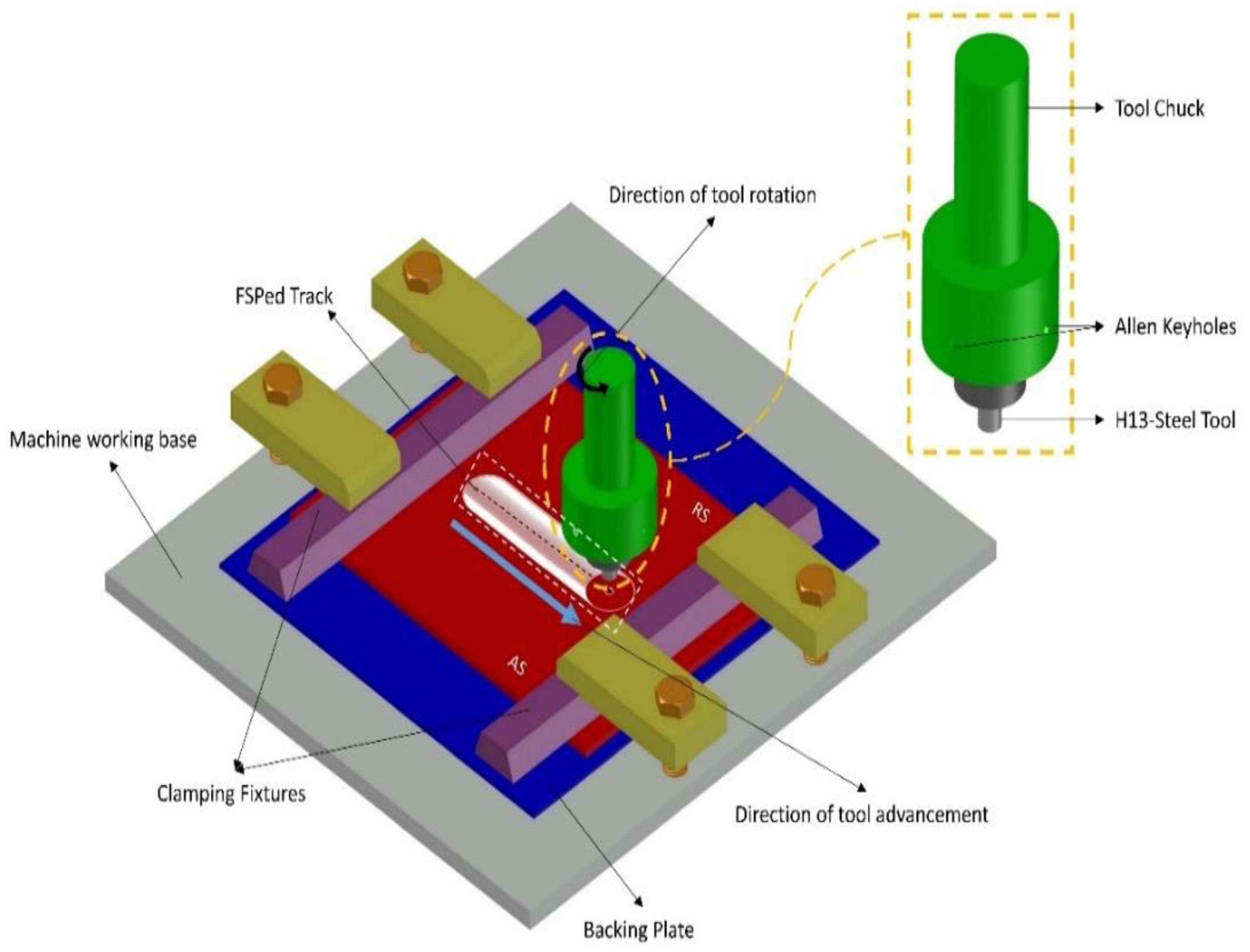
2.1. Experimental Procedures

The base material as AZ91 magnesium alloy with 150 mm × 100 mm and thickness of 6.35 mm was procured from Samnai, Malaysia. The untreated BM’s typical grain size and microhardness are ~70 μm and 62 HV, respectively. The chemical compositions of AZ91 in weight % are: 8.3–9.7 Al, 0.35–1 Zn, 0.15 Mn, 0.10 Si, 0.005 Fe, 0.030 Cu, 0.002 Ni, and the rest was Mg. China’s Beijing FSW Technology Co., Ltd. (Beijing, China) provided the automated CNC FSW machine that was used to process the AZ91 sample. H13 tool steel, commonly used to process soft and hard materials, was employed for this process. The tool with a 20 mm shoulder diameter (D), a 6 mm pin diameter (d), and a 3 mm pin height was used. According to Guanghua et al. [27], the tool underwent heat treatment to harden it to a value of 55HRC. To provide finer grain structure in the SZ, D/d should be maintained greater than 3 [28]. To understand and track the reason behind the emergence of defects in respect to the material flow with the novel SPH technique, the study is carried out without any angle. The mesh-free method has tested at this level to ascertain the authenticity of SPH formulation with the Johnson–Cook constitutive material law and the Mie–Grüneisen equation of state. This study will be considered as a fundamental basis for the future studies. The BM must be degreased with acetone to eliminate extraneous objects before being clamped for processing. Figure 1 shows the whole setup for friction stir processing.
The temperature on the surface of the BM was measured by means of a Fluke-made Ti32 Thermal Imaging Camera with a range of −20 °C to +600 °C (with a measurement precision of ±2 °C). Three snaps of images were taken to correlate and interpret the thermo-mechanical behavior during the numerical model’s assessment with experimentation. Thermal images were taken during the plunging dwelling and at ~14 mm from the plunging point. The working area of the tool was ~100 cm away from the Ti32 thermal imaging camera, which was positioned across the processing direction. Electrical Discharge Machining (EDM) was used to cut the sample measuring 2 cm × 2 cm from the friction stir processed (FSPed) surface.
In contrast, samples were cut at the transverse section to examine their macrostructure and microstructure analysis. According to the ASTM E3-11 standard, the samples were prepared. Silicon carbide papers having grit from 200 to 1200 were then used to grind and polish the sample. The specimen was rotated 90 degrees after each addition of grit level, then polished with a diamond slurry. According to ASTM E407-07, specimens were etched with a picral reagent after polishing. The macro and microstructural characteristics were recorded using an optical microscope (OM) manufactured by Leica. A Vick-hardness tester (LM 247AT-Leco, HQ: LV Ave, St. Joseph, MI, USA) was used to mechanically assess the surface hardness in line with ASTM E384-17, using 200 gf for a dwell time of 10 s. From our preliminary trials [29], the parameters used for processing the material is as shown in Table 1.

2.2. Numerical Model Description

Vehicle collisions, drops and impacts analysis, high-velocity blasts, and explosion effects, and other challenges, have all been solved using the Altair RADIOSS solver. It is worth noting that each of the aforementioned issues entail high plastic deformation. RADIOSS is a suitable tool for designing and analyzing the issue since complex environments like aerospace, military businesses, automotive, and R&D centers utilize the Hyperworks framework to understand and forecast design and analysis behavior. The numerical modeling of FSP indicates a challenge that includes non-linear material behavior due to the high strain rates and temperatures. Therefore, FSP is employed with the Altair RADIOSS 2022 solver to resolve the intense plastic deformation issues. SPH has a remarkable ability to translate complex physics into smoothed particle formulations; as a result, it has been used to solve a wide range of solid and fluid mechanics issues [30]. Furthermore, the SPH method is to be considered for tracking the temperature and particle distribution during the process with the mesh-free Lagrangian technique. In addition, the following assumptions were used in this research to rationalize the issue: (1) the tool and backing plate are non-deformable isotropic rigid body (/MAT/LAW1); (2) the workpiece is homogeneous and isotropic, modelled as elastoplastic material (/MAT/LAW4); (3) when the process temperature approaches the material’s melting point (803 K), no heat is transferred to the workpiece; (4) the ambient temperature of 298 K is surrounded on all free surfaces of the workpiece, backing plate, and tool; and (5) tool pin and backing plate are in touch with the top and bottom surface of the workpiece composed from SPH particles. Different boundary conditions are applied to distinct specimen surfaces during the process and are highlighted in Figure 2.

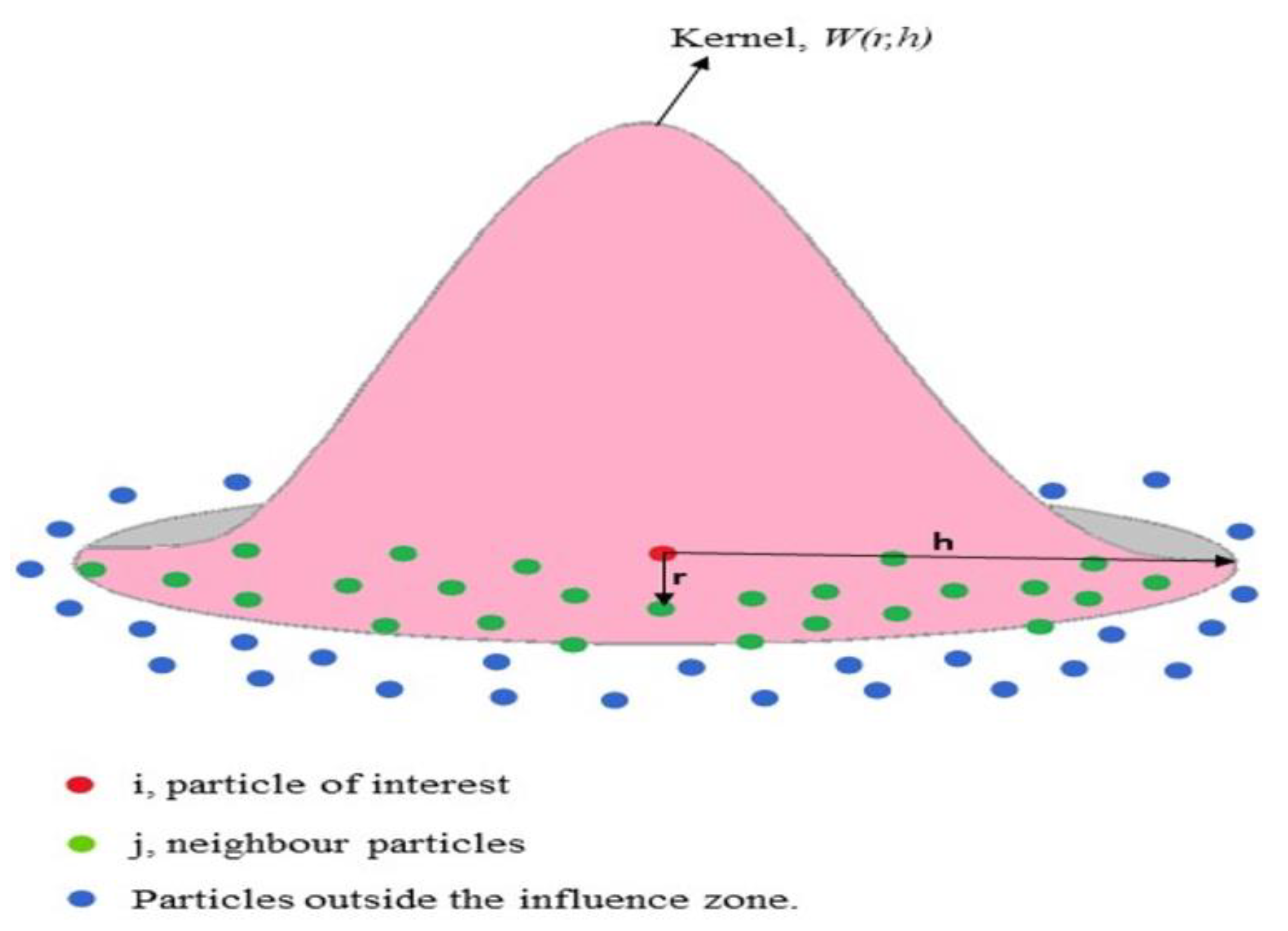
2.2.1. SPH Formulation

Gingold, Monaghan, and Lucy created the SPH mesh-free technique in 1977 to solve problems in astrophysics; it was later used in studies on ballistics, volcanoes, and oceans. This innovative method does not require any background mesh. A Lagrangian formulation is achievable due to its mesh-free nature, which is crucial for modelling the FSW/P process. Due to the Lagrangian formulation, the whole history of stress, strain, temperature, and other variables may be carried by each calculation point in the model. SPH is exceptionally well suited for massive deformations and used to quantitatively determine the FSW/FSP behavior [31,32]. Researchers are thus interested in employing this method to monitor materials that have undergone significant deformations and stresses. The SPH approach was designed to solve hydrodynamics issues that are essentially partial differential equations (PDE) of field variables like density, velocity, energy, etc. The continuous integral representation of a function and/or its derivatives is the first step in an SPH formulation for a partial differential equation. The discretized summation process is the second stage. The first stage has been referred to as kernel approximation because in this approach, assessing the smoothing kernel function and its derivatives is a prerequisite for approximating a function and its derivatives. By combining the values of the closest neighbors, the estimate of the field variables for each particle will later be approximated. Particle approximation has been used to describe the second phase. In SPH, interpolation is carried out at a nodal point by weighing the total values (or gradients) of field variables at nearby nodal points. Figure 3 illustrates this interpolation technique graphically. The weighting function, known as the SPH kernel, often has a Gaussian-like shape. Popular options include Monaghan’s cubic spline [33]. This technique solves the set of field equations (at this instance, solid-body conservation equations) by extrapolating from a set of j particles under the influence of ith. The smoothing length, ℎ, determines the size of the influence domain. The initial particle spacing, Δs, is often multiplied by the smoothing length scale factor (ℎscale) to obtain the smoothing length.
= scale Δ s
The fundamental tenet behind the SPH approach is to approximately interpolate a collection of partial differential equations (PDEs) into a set of ordinary differential equations. A convolution integral approximates a continuous function:
f ( x ¯ ) =   f ( x ¯ ) W ( x ¯ x ¯ , h ) d x ¯
The smoothing kernel function W( x ¯ x ¯ ,h) is dependent on both the spatial separation between the computed ( x ¯ ) and interpolated ( x ¯ ) locations as well as the smoothing length h. For a collection of discrete material points, the continuous SPH interpolation equation is therefore expressed as follows:
f ( x i a ) = j = 1 N i m j ρ j f ( x j a ) W ( r , h )
Here, 𝑥i and 𝑥j is the vector spatial location for i and jth particle. The size of the effect domain of the jth on a particle 𝑖 is thus determined by the smoothing length h. 𝑚j, 𝜌j are the mass and density of a jth particle, and 𝑟 = | x i a x j a |. A significant portion of the computing time for the SPH approach is spent determining the neighbor’s list [34].

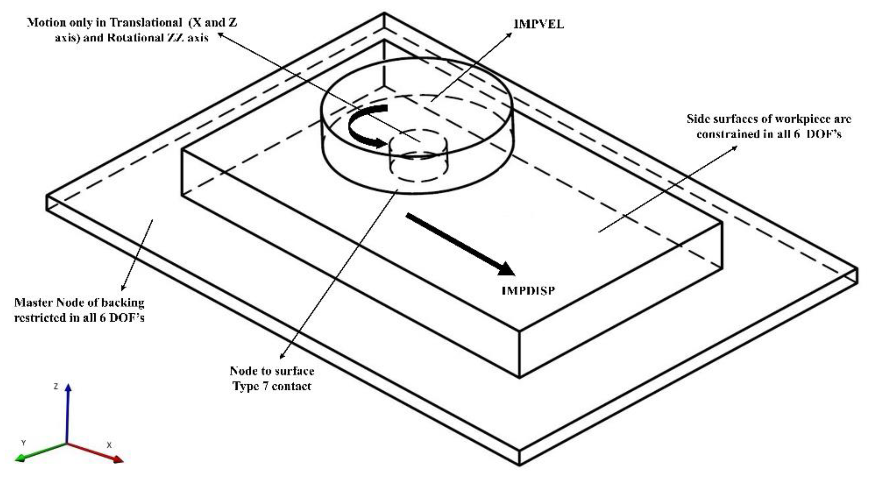
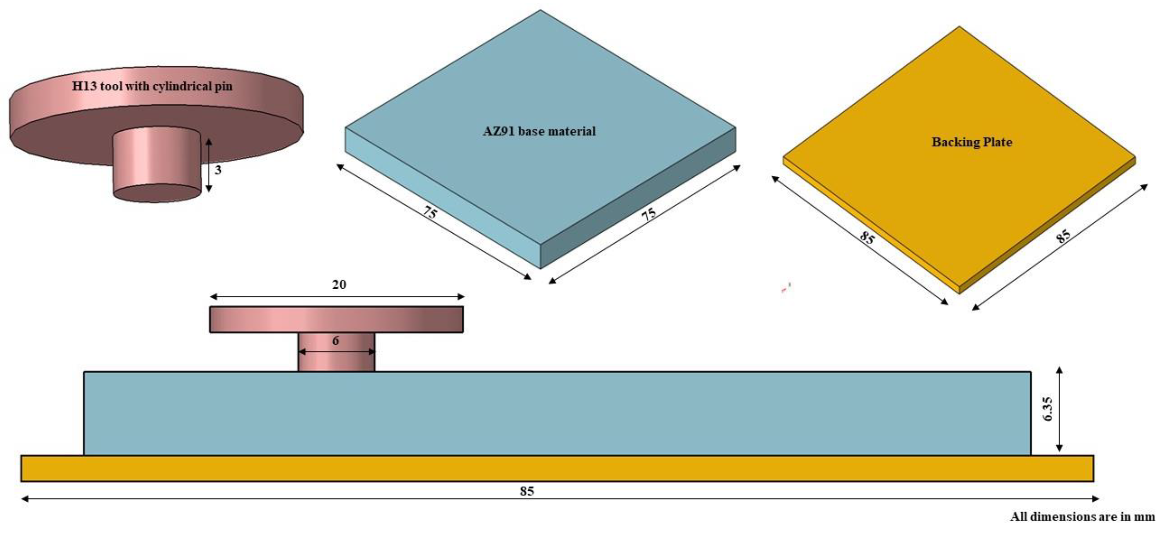
2.2.2. Workpiece and Tool Models

Autodesk AutoCAD 2022 was used to model the workpiece, tool, and backing plates. Together, assembly of modelled parts was then imported into Altair RADIOSS. In general, only the treated zone is affected by plastic strain, material flow, and temperature distribution. Moreover, the thermal cycles responsible for softening and microstructure modification occurred in this SZ and a narrow zone near it. As a result, the geometries of the backing and base material were less than those used for the experiment, reducing the simulation run-time without sacrificing the results’ accuracy. For convenience, the dimensions of the parts are shown in Figure 4. Approximately 1159 tetra elements and 14,450 hexa elements, respectively, were used to mesh the tool and the backing, which were both represented as rigid bodies. During the actual FSP process, the workpiece experienced a high strain rate and plastic deformation; thus, the SPH mesh-free technique was employed for the AZ91 workpiece with 39,375 nodes to withstand significant distortion. The pitch between the SPH particles was set such that the upper and lower array of SPH particles touched the tool pin and backing plate and was found to be ~1 mm. This was performed in order to understand material movement near the pin and workpiece without any prior gap.
The process parameters used in numerical modelling were the same as those used in experimental tests, as shown in Table 1. A 64-bit system running an Intel(R) Xeon(R) Gold 5115 CPU@2.40 GHz, 128 GB of RAM, and 10 cores was used for simulating three phases of FSP. For the 30 s simulation, it took around a total of 6 days of computational time to complete.

2.2.3. Material Model

To represent the material response in FSP, choosing a suitable constitutive law that captures the interplay of flow stress with temperature, strain rate, and plastic strain is crucial. For solid-state joining processes, the Johnson–Cook (JC) model has been frequently utilized because it considers temperature, strain, and strain rate effects. The Johnson–Cook flow stress model is given by Equation (4).
σ = ( A + B ε n ) [ 1 + C l n ( 1 + ε ˙ ε 0 ˙ ) ] ( 1 [ T T r o o m T m e l t T r o o m ] m )
The symbols designate the following. σ: material flow stress [Pa]; ε : equivalent plastic strain; ε ˙ : plastic strain rate [s−1]; ε 0 ˙ : reference strain rate [s−1]; Troom: room temperature [°C]; A: initial yield stress [MPa]; B: hardening modulus [MPa]; C: coefficient depending on the strain rate; m: thermal softening coefficient; n: work-hardening exponent. These parameter values for AZ91 are as depicted in Table 2 [15].
The material and thermal properties of AZ91 Mg alloy and H13 tool steels used for the numerical simulation are shown in Table 3 [16,35].
The hydrodynamic pressure was calculated using the Mie–Grüneisen equation of state (EOS), compatible with the assigned MAT/LAW4 by the RADIOSS. The values opted for Mie–Grüneisen are shown in Table 4.

2.2.4. Friction Model

Contact state impacts key model output features such as temperature generation, stress, forces, strain distribution, and the emergence of defects since the FSP involves excessive plastic deformation. Thus, setting the appropriate contact state between the H13 steel tool and AZ91 is key to the simulation. Frictional heat production between the tool’s shoulder and the specimen’s top is considered the primary heat source. In this simulation, Coulomb’s law of friction governs the frictional interaction between the tool and the shoulder and is given by
τ f r i c t = μ σ n
τ f r i c t indicates the frictional stress, σ n is shear yield stress, and µ is the coefficient of friction. According to the verified model by Bagheri et al. [15], a friction coefficient of 0.3 is taken into account in this study. In RADIOSS, node-to-surface global contact was assigned for the tool-workpiece and between the tool and backing plate.

3. Results and Discussion
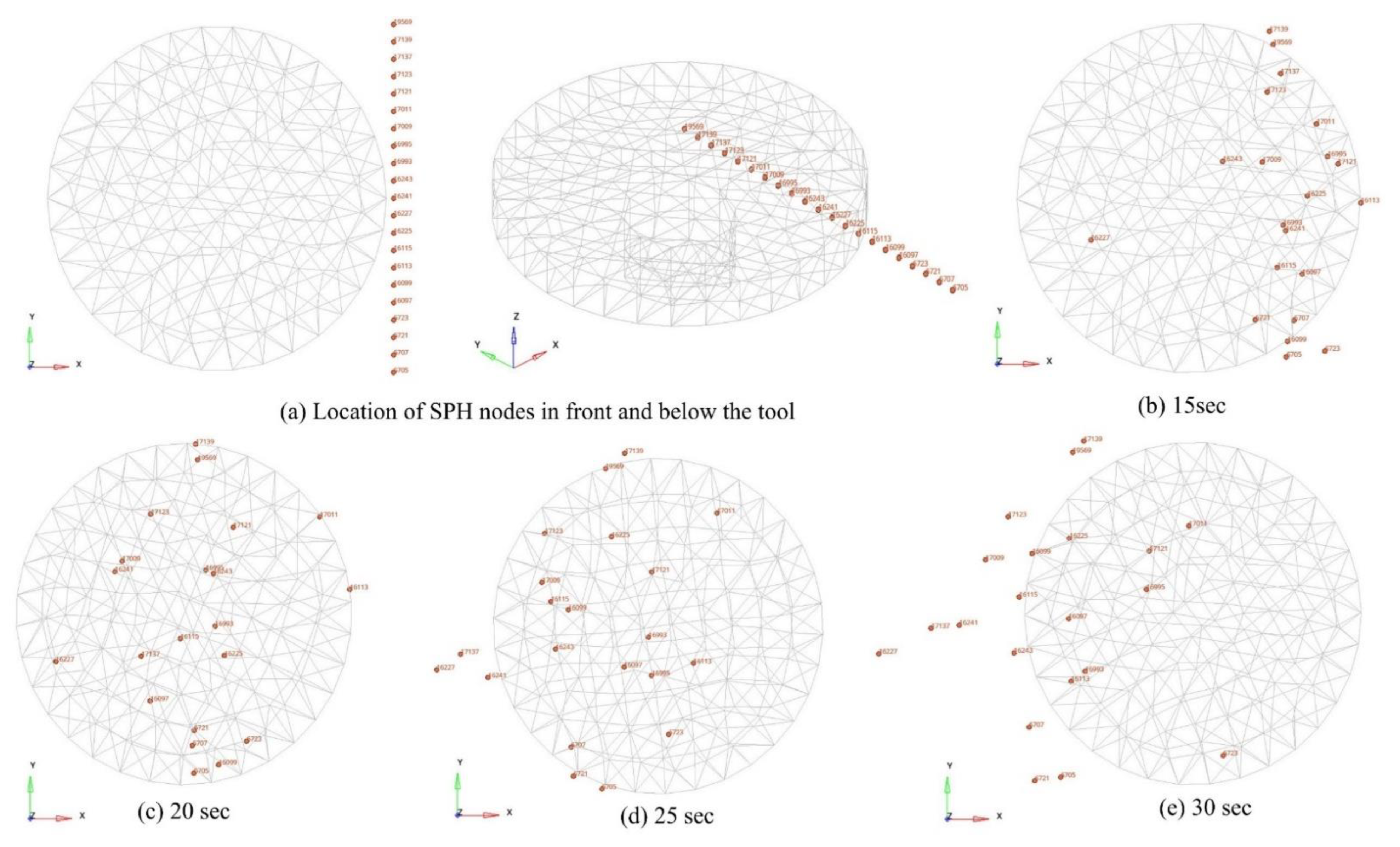
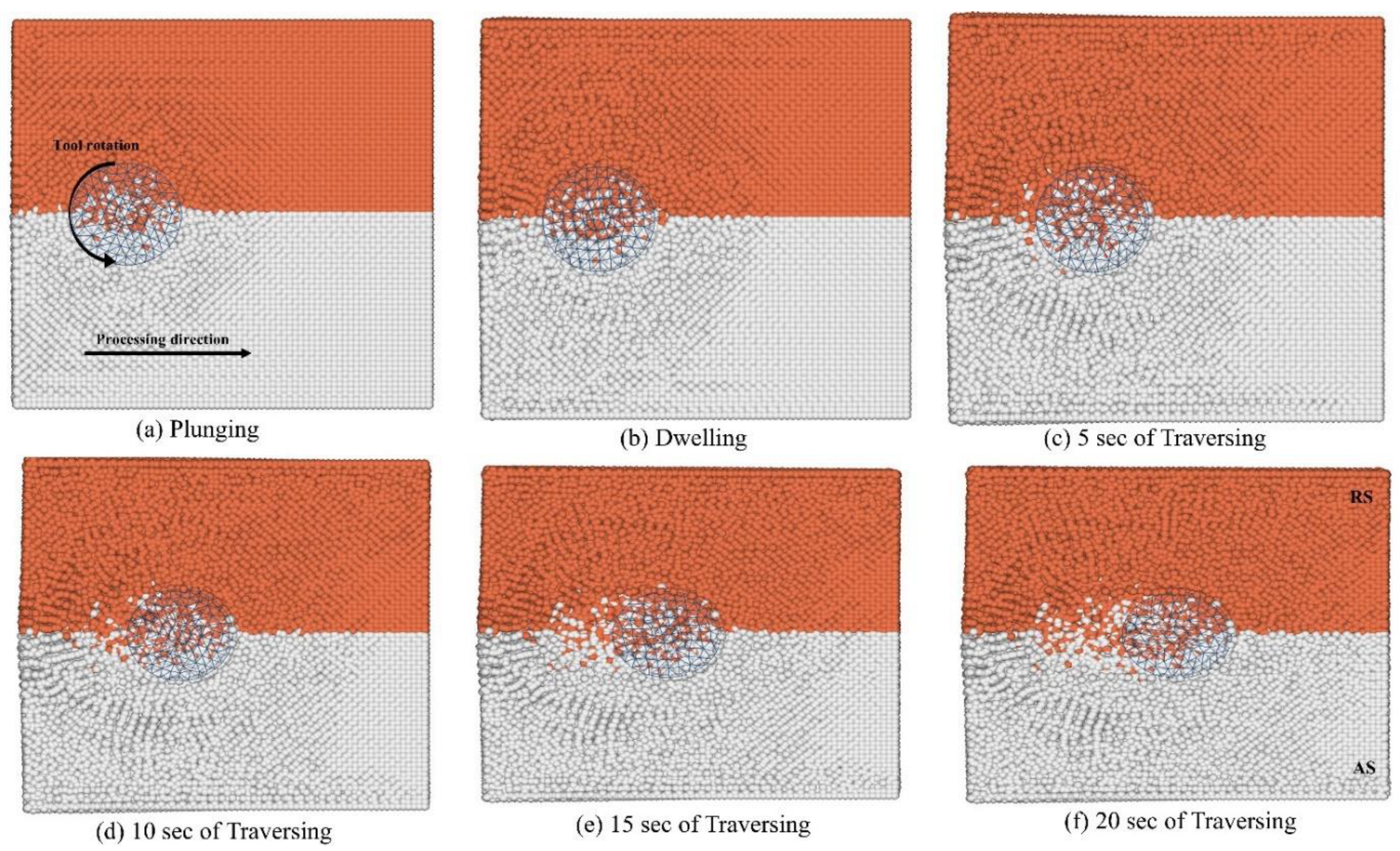
3.1. Material Flow

Increased frictional and normal pressure caused by the tool sticking to the workpiece can be the only effect of increased tool speeds. When the tool speed is lower than the one chosen, the main issues are tool slip and lack of plastic deformation. It was evident from our previous experimental results that the process settings were not causing any aberrant material transitions that indicated the balance of the slip-stick phenomena. SPH node tracking, which records the flow pathways, was explored to better estimate the mechanism of material movement. Figure 5 and Figure 6. depict the material flow during the friction stir processing of the AZ91 magnesium alloy. The SPH nodes are first located as seen in Figure 5, an array of 21 nodes at the edge of the shoulder and 1 mm below the workpiece surface; 16,241 indicates the center node, whereas the extreme upper and lower nodes were positioned on RS and AS, respectively. The farthest top and bottom SPH nodes are away from the location of the tool rotation; hence, those nodes had little movement. However, near the tool pin, nodes 17,009 and 16,995 from the RS are deposited toward the RS rather than the AS because the tool pin’s peripheral velocity does not impact them.
Due to the impact of tool pin velocity, nodes 16,993, 16,243, and center node 16,241 migrated multiple times around the edge of the pin before depositing 30 s later on the AS. Nodes 16,097, 6723, and 6721, which are further from the pin, came later under the effect of pin velocity impact. The SPH nodes eventually return to the AS after revolving around the pin. At the conclusion of the traversing phase, it is clearly visible. This behavior, however, was not seen in the nodes that were close to the pin and dispersed over the AS and RS after the tool passed. Moreover, near the center node, the SPH particles 16,227 and 16,225 show chaotic behavior. In a semi-circular motion, node 16,227 travelled from the front to the back of AS.
All the material nodes at the AS, RS, and center that are close to the tool were supposed to migrate in the AS direction. While some delivered, others maintained their positions. Because of this, the material flow was inadequate due to the unlevelled stick-slip situation. With a 0° tool tilt angle, less material was deposited in the AS due to the lower tool’s forging force and decrease in pressure, leading to the observation of a wormhole defect. This theory that the tool’s rear side cavity wasn’t sufficiently filled throughout the processing’s advanced motion was in accordance with William’s study [36]. Therefore, it is advised to enforce the inclination of the tool in the future to improve material flow without any inherent defect.
Figure 6 shows the simplified material flow at distinct phases, from plunging to traversing. White smoke SPH nodes were showing the AS, and the orange color side indicates the RS of the material. Although the tool shoulder was taken into account, it was found that the pin rotation has a more profound impact on material flow during the dive. This results from the phenomena wherein the FSP tool acts as a drilling tool during plunging, boring a pin-sized hole into the workpiece. The center of the tool pin was anticipated to be more vulnerable to plastic deformation and greater strain rates. As a result, the pin core showed more evidence of workpiece material mixing than any other area on the material’s surface. A similar phenomenon is clearly discernible in Figure 6a, as both color sides of SPH nodes exhibit higher degrees of mixing near the rim of the tool pin.
Together, the tool shoulder and pin effect on the material flow during the dwelling stage causes a greater intensity of material mixing with temperature than during the plunging stage. At this juncture, the material flow is not restricted to the pin, and plunge depth plays a vital role in spreading the material flow to the shoulder. As the tool rotates at the same location for 5 s, it pulls the material from the RS and delivers it to the AS, and the same was also experienced on AS. Due to the tool’s vortex flow velocity, it may be inferred that the material is spinning 360° near the tool. However, owing to the effect of centripetal force, specific SPH nodes are detected farthest from the tool center, at the border of the shoulder periphery. Thus, from Figure 6b, the intensity and counts of the flow of SPH particles on AS were found to be little more than that of plunging.
After 5 s of traversing, the tool nearly travelled along the x-direction beyond the radius of the tool pin. The mixed color metallic tones created at the tool’s back side can be attributed to the increased deposition of SPH material nodes as it moves farther forward. Combined orange and smokey shade nodes appeared to be a single unit, indicating the severe plastic deformation that caused the tool pins to cling to one another. From Figure 6c, the tool shoulder exerts pressure on the material upfront and tightens or narrows the area, resulting in SPH nodes being crushed between the edge and the next layer of AZ91. This creates the constriction that will eventually produce a flash.
For a smaller size of the workpiece used in the simulation than the experiment, there was little bulging at the sidewalls owing to the surplus heat generated via friction; as a result, a greater temperature was seen in traversing than in the dwelling. After 20 s of traveling, a layer of SPH nodes creating a flash from the previous phases for both AS and RS at the shoulder trajectory may be seen clearly in Figure 6d. SPH nodes from the tool’s front were gradually swept up and positioned at the back to fill the hole left by the tool pin. In experiments, the onion rings are built up due to this phenomenon, and the pitch of the onion rings is revealed by the gap that is left by the tool as it advances. At the tool’s rear, mechanical links between the self-material are visible and seem to be a complete intermixing of the surface of the base material devoid of major flaws. The flow beneath, however, is not entirely detected owing to insufficient tool forging force of the shoulder at the rear side, which causes the production of the wormhole defect, as previously mentioned.
Figure 7 depicts the plastic strain of SPH nodes located at the position shown in Figure 5a; SPH Nodes 6705, 6707, 19569, and 17,139 are far from the shoulder and pin and hence have the lowest plastic strain without any notable movement in their original position; 17,137 from RS, 6723, and 6721 from AS show nearly equal plastic strain. However, node 17,137 has a high plastic strain, and the deposited location is attributed to the same on AS at the end of the traversing phase. RS SPH node 17,123 has lower plastic deformation than the extreme nodes at AS, although more plastic strain was expected. As it kept its place on RS rather than AS, this may be the cause of the flaws on the AS emerging. The material flow of RS included an exceptional 17,121 node, which represents the maximum amount of plastic strain achievable due to its attachment to the pin and rotation along the pin motion. It was shown to migrate along the area around the pin, as shown in Figure 5b–e. This kind of unusual node behavior was noted in the research conducted by Tutunchilar et al. [17]. Uncontrolled turbulent behavior of nodes (16,225 and 16,227) adjacent to the center node was noticed as they swing along the AS only and thus have a low plastic strain. Despite being in the center, node 16,241 holds less strain than the adjacent node, which may be ascribed to the effect of pin velocity. Nevertheless, both nodes extended in the direction of the AS as predicted.
Node 17,009 drifted internally closer to the pin, made full and partial rotations of it, and was found to have been lodged at the back side of RS rather than AS. This is because the tool without any tilt angle delivers insufficient compressive force and lateral frictional force, which are considered key factors in removing the volume of material from RS. In the same way, nodes 16,243, 16,993, and 16,995 were on the same RS sites. Apart from 16,993, the other two SPH nodes also experienced substantial levels of plastic strain due to the pin effect during tool advancement. Moreover, 16,993 and 16,995 exhibited the opposite behavior to the condition of reduced fluidity on the tool’s backside caused by a lack of tool tilt angle.

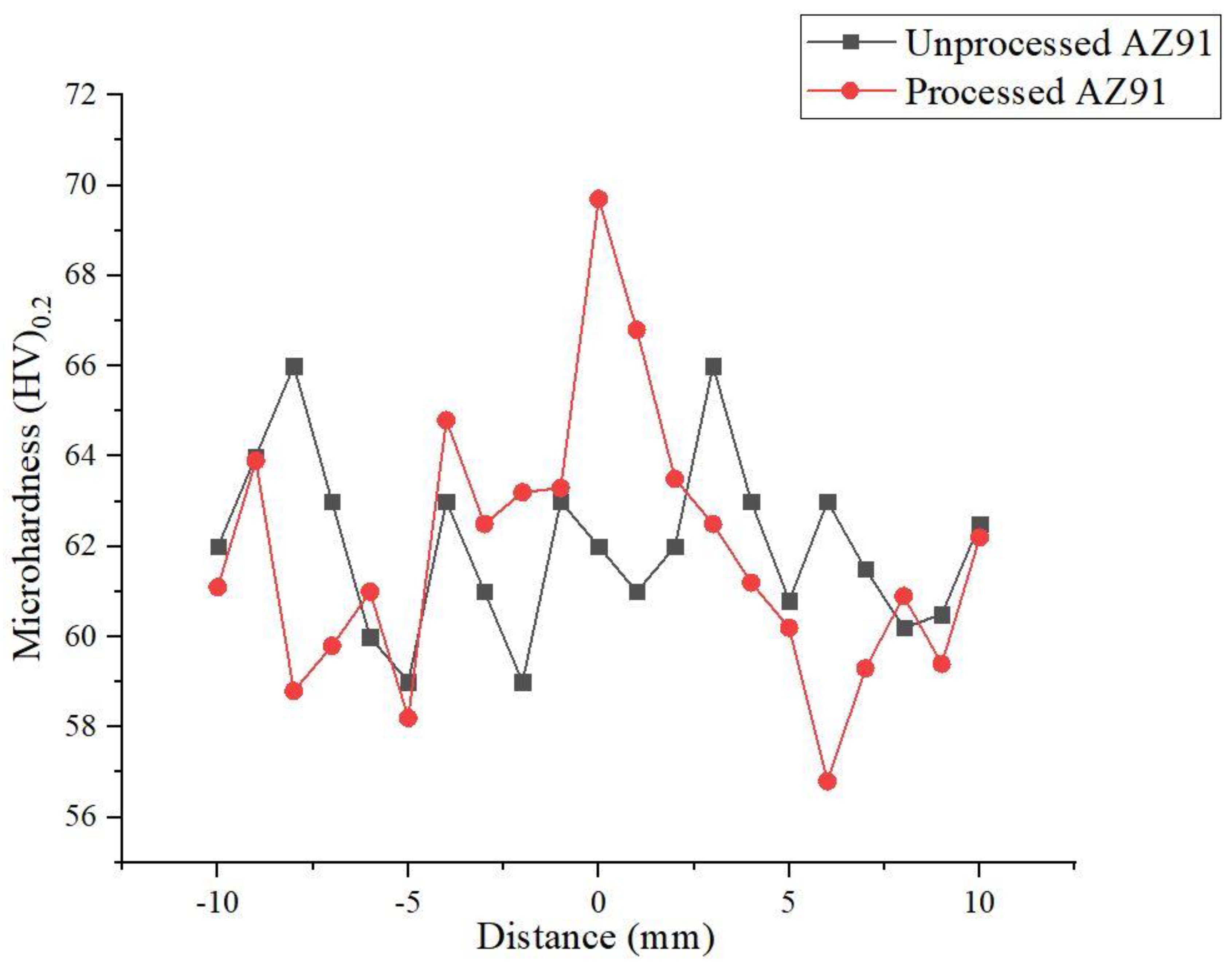
3.2. Morphology and Microhardness

Due to the severe plastic deformation of the tool pin, the selected parameter has the potential to create dislocations. The temperature-compensated strain rate parameter reveals the ability of variables to improve the microstructure and, as a result, the hardness. Altair’s post-processing tool, Hyperview, has a customized section cut panel that enables cutting the planar or deformable sections of a model. This made it helpful to reveal and understand the internal feature of the simulated model preferable to correlate with the experimental morphology. The architecture of obtained morphology by the x-x axis section for numerical simulation and the cross-section of the treated material under an optical microscope are shown Figure 8a and Figure 8b, respectively. In Figure 8a, the cut section reveals the unfilled gap, and the same was found in experimental morphology, as depicted in Figure 8b. This unfilled cavity in processed material, termed a wormhole, was observed in the center of the advancing side, below the tool shoulder. The pin velocity has the lowest value at the trailing edge of the tool’s advancing side, and because of the reduced pressure, the material scarcely enters the area. The reduction in the pressure and inadequate flow of material is brought on by the lack of any tilt angle and is considered the main reason for the cavity formation. Thus, it was mostly observed at the advancing side to the trailing edge, and the same was noticed by Tutunchilar et al. [17]. The occurrence of a material defect occurs when the stick-slip condition is out of balance. It is thus advised to use a tool tilt angle to balance the material flow from the area in front of the tool pin with that flowing into the empty region behind the pin tilt angle [36]. The probability for defects to emerge in relation to the minimal flow of SPH material nodes is accurately predicted and validated by the current numerical model. To estimate the fault characteristics with its proportions for longer track runs of FSP, location, size, and position must be further modelled.
As illustrated in Figure 9, the microhardness of the treated material was measured on its transverse section and showed different variants. According to findings provided by Commin et al. [37], the non-precipitation strengthening magnesium alloys have different hardness distributions across the treated material because of the grain structure, dislocation density, or texture development. The pin diameter zone showed the maximum hardness and was determined to be 68 HV, a 12% increase over the BM. The enhancement in the microhardness at the stirred zone is the cumulative effect of grain refinement and partition of intermetallic phase β-Mg17Al12 in AZ91 magnesium alloy. Process variable values that increase or decrease above the chosen may alter the slip system index and result in poor hardness because of the coarsening of the grain. The Hall–Petch relationship denotes a refinement-induced increase in hardness. However, the microhardness of the processed material was found to be less than that of the unprocessed material at certain spots due to inadequate material flow and wormhole material defects.

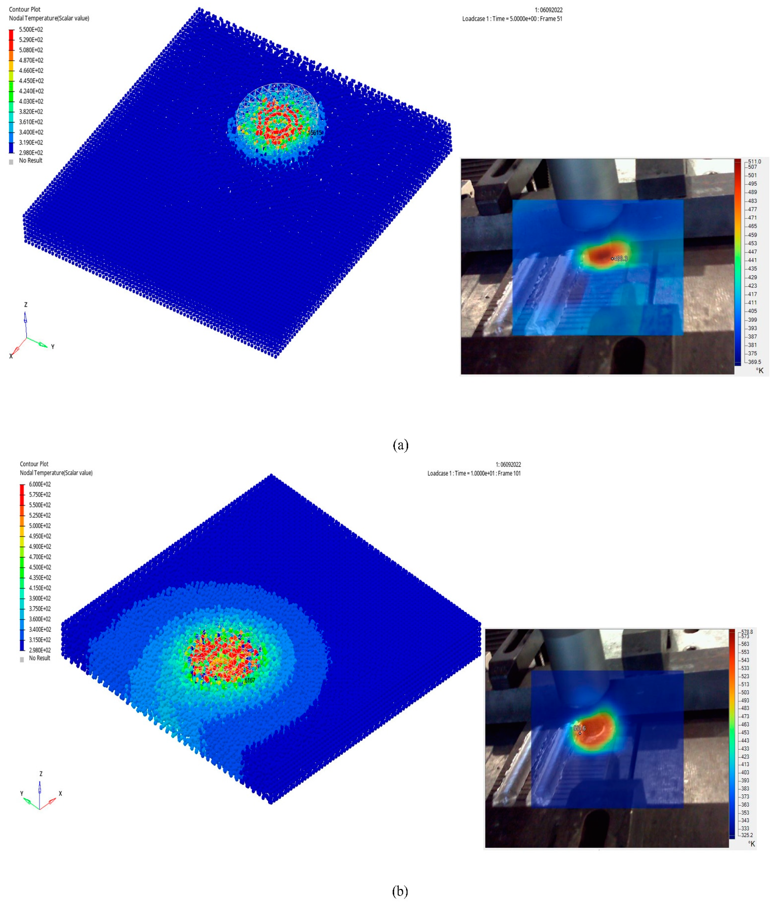
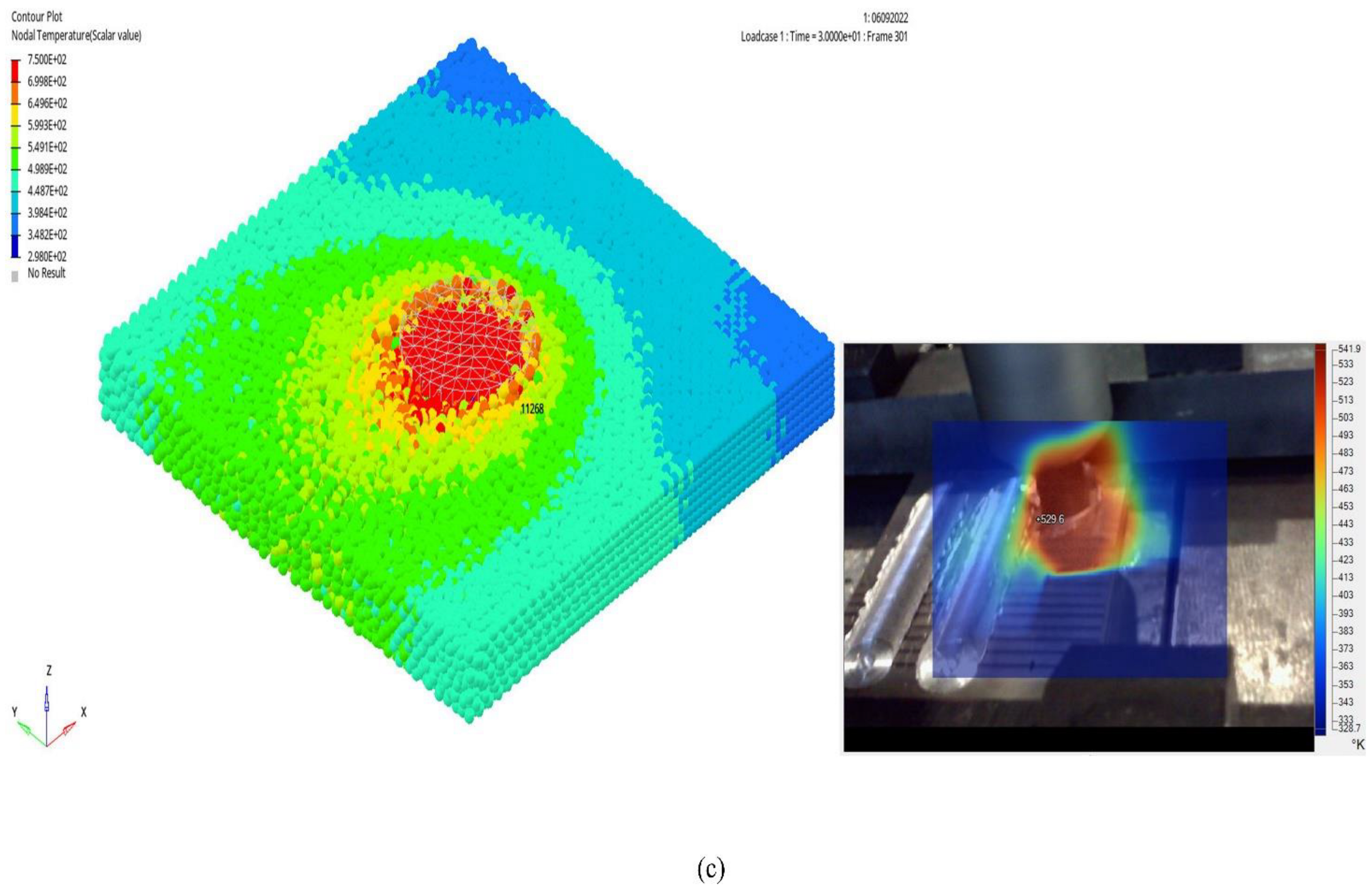
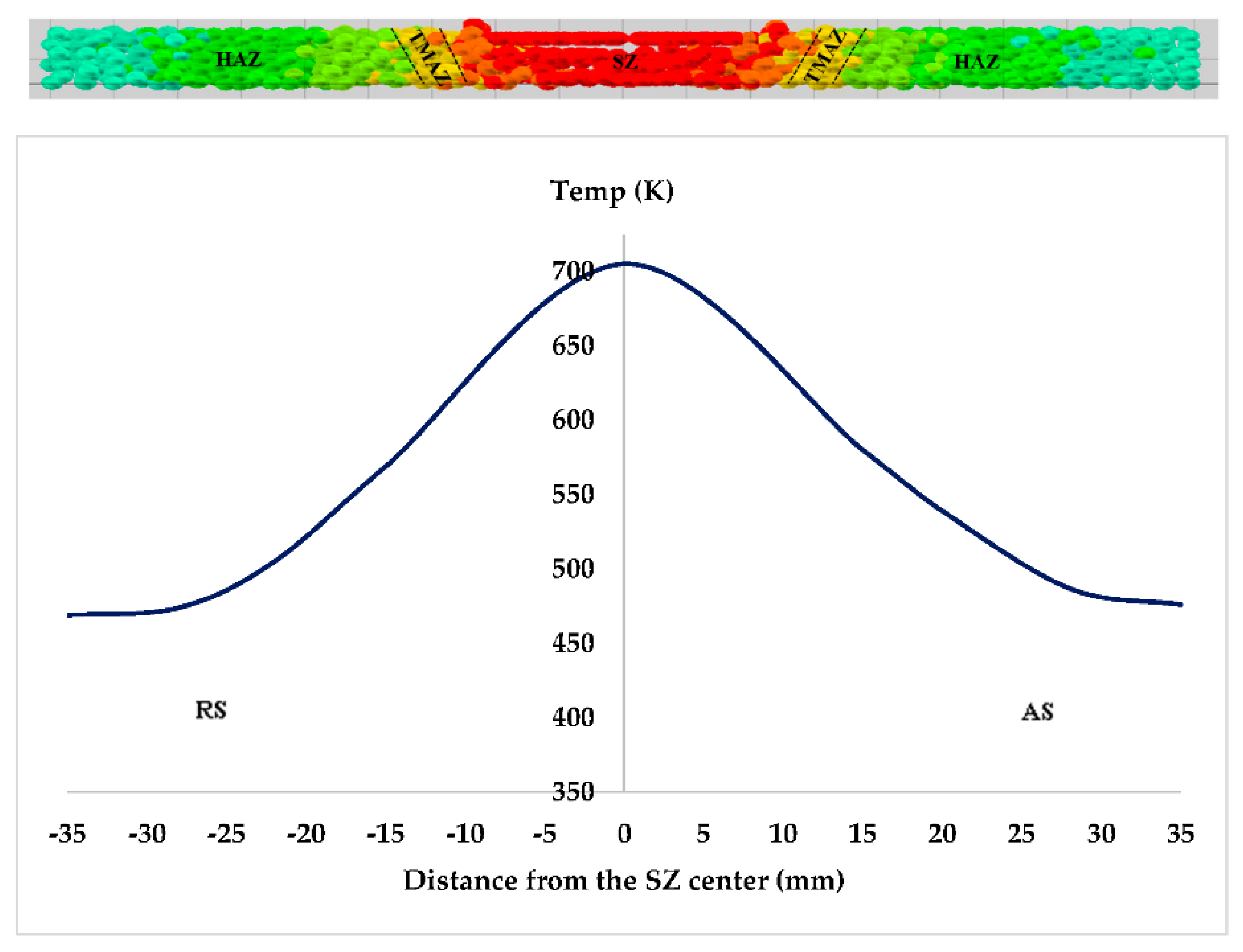
3.3. Temperature Distribution

The adequate heat was needed to make the material soften. Thus, the preferred parameters root the material particles and SPH nodes to flow effortlessly around the tool pin. If the process parameters are chosen above or below the extreme level, inadequate or excessive heat generation causes aberrant stirring and makes it impossible to predict the validity of the model for 0°. Edge friction and plastic deformation contribute to the heat produced during the FSP. The contact area and friction factor between the tool and the workpiece, as well as rotating speed and shoulder pressure, all impact the frictional energy. At a distance of 10 mm from the center of the processing zone, temperature measurements were taken for each of the three phases: plunging, dwelling, and traversing. The simulation results were then compared to the results of the measurements. The thermal profiles were well-aligned at these locations, with the maximum percentage error deviation being about 18%.
Figure 10 depicts the thermal history of the AZ91 processed samples from plunging to traversing via both simulation and experimentation. On the plate, the tool is positioned in the middle of the workpiece’s surface along its width. The tool starts revolving as soon as it is penetrated 3.3 mm into the workpiece at a constant plunge speed of 40 mm/min. Upon attaining the required depth, the shoulder almost touches the top surface of the workpiece, and the plunge stroke is considered finished after 4.95 s. When the tool is penetrated in cold AZ91 magnesium alloy, the stirring motion causes significant plastic deformation and considerable heat. The temperature obtained on the retreating side during the plunging at 10 mm from the center zone during experiments was 488.3 K using the Ti32 camera.
In contrast, the simulation temperature obtained by extracting the SPH node (16615) at the exact specific location was 413.5 K. There was a significant increase in temperature during the 5 s dwell time and resulted to be 551.6 K experimentally and 489.6 K from the simulation at 10 mm away from the center of the processed zone and on the advancing side. The peak temperature is often higher during the dwelling phase than during the other two stages because the tool spends more time with the workpiece at the same spot. Before the tool’s advancing starts, the material softens at this stage, improves material flow, prevents defects, and lengthens tool life. The temperature was stabilized during the traverse period, and the experimentation temperature on the advancing side reached 529.6 K. In a numerical simulation, ~60 K increase in temperature was observed when compared to the experimental values for the traverse phase rather than a decline following dwelling as the heat is only conveyed by friction and deformation. Moreover, because of smaller workpieces, heat generation becomes dominant over the heat dissipation. The SPH technique accompanying the conduction and convection with all three phases (plunging, dwelling, and traversing) tremendously increases the computational time and cost. Thus, the SPH model was restricted by the heat produced by friction and plastic deformation.
It is clear from Figure 10 that maximum temperatures were recorded at the locations nearest to the stirred zone. The temperature dropped as the distance from the stirred zone increased because there was less heat generation, and the tool heat source was further away. The same was also depicted in Figure 11. As for the entire process, the tool is plunged to the 3.3 mm depth of the total available 6.35 mm thickness of the plate, and from the bottom surface to the top surface, the temperature at the SZ increases. Furthermore, the treated material’s peak temperature gradient in the stir zone along its thickness direction was minimal. The SZ over the top surface showed the highest temperature of 705 K. For the hardening precipitates in AZ91, it is anticipated that this temperature exceeds the solution temperature [38]. During the FSP, the shoulder generated most of the heat because the contact areas between the workpiece and shoulder are substantially more prominent than those between the pin and the workpiece. Although the shoulder has a higher linear velocity than the pin’s smaller radius, a non-symmetric temperature distribution was noted in Figure 11. The tangential velocity direction was the same as the forward velocity vector. Hence, the temperature was found to be higher on the advancing side of the treated material. The maximum temperature gradient between AS and RS for the FSPed material was 34 K, whereas the minimum gradient was 7 K, consistent with Asadi et al. [35].
Frictional heating and adiabatic heating are both factors in the overall context. Interface surface velocity and frictional coupling affect frictional heating (coefficient of friction). As a result, temperature generation must grow from the center of the tool shoulders to its edge, as seen in the dwelling phase of Figure 10. According to the study by Schmidt et al. [39], the tool pin also contributes to some frictional heating during the traversing phase, in addition to the plastic deformation that is produced. Apart from that, adiabatic heating is apparently going to be highest at the pin and tool shoulder surface and diminish away the vicinity. Figure 11 provided evidence for both the frictional and adiabatic heating phenomena. Temperature ranges for all three phases were observed to be 47% to 87% of the materials melting, and thus making it obvious that the entire process is in the solid state.

4. Conclusions and Recommendations

In the current study, using Altair RADIOSS software and the SPH mesh-free Lagrangian approach, the FSP of AZ91 magnesium alloy was thermo-mechanically modelled. Using the software’s advanced section cut feature, the simulation successfully predicted the temperature, material transition, and emergence of a defect in the FSPed material. SPH nodes were used to assess the material flow around the tool. The findings showed that:
  • A maximum error of 18% was recorded by comparing the experimental temperature distribution for the plunging, dwelling, and traversal phases with the simulated data.
  • Simulated temperatures during the traversal phase were greater than experimental temperatures as the heat was only transported by friction and plastic deformation, and the workpiece was smaller.
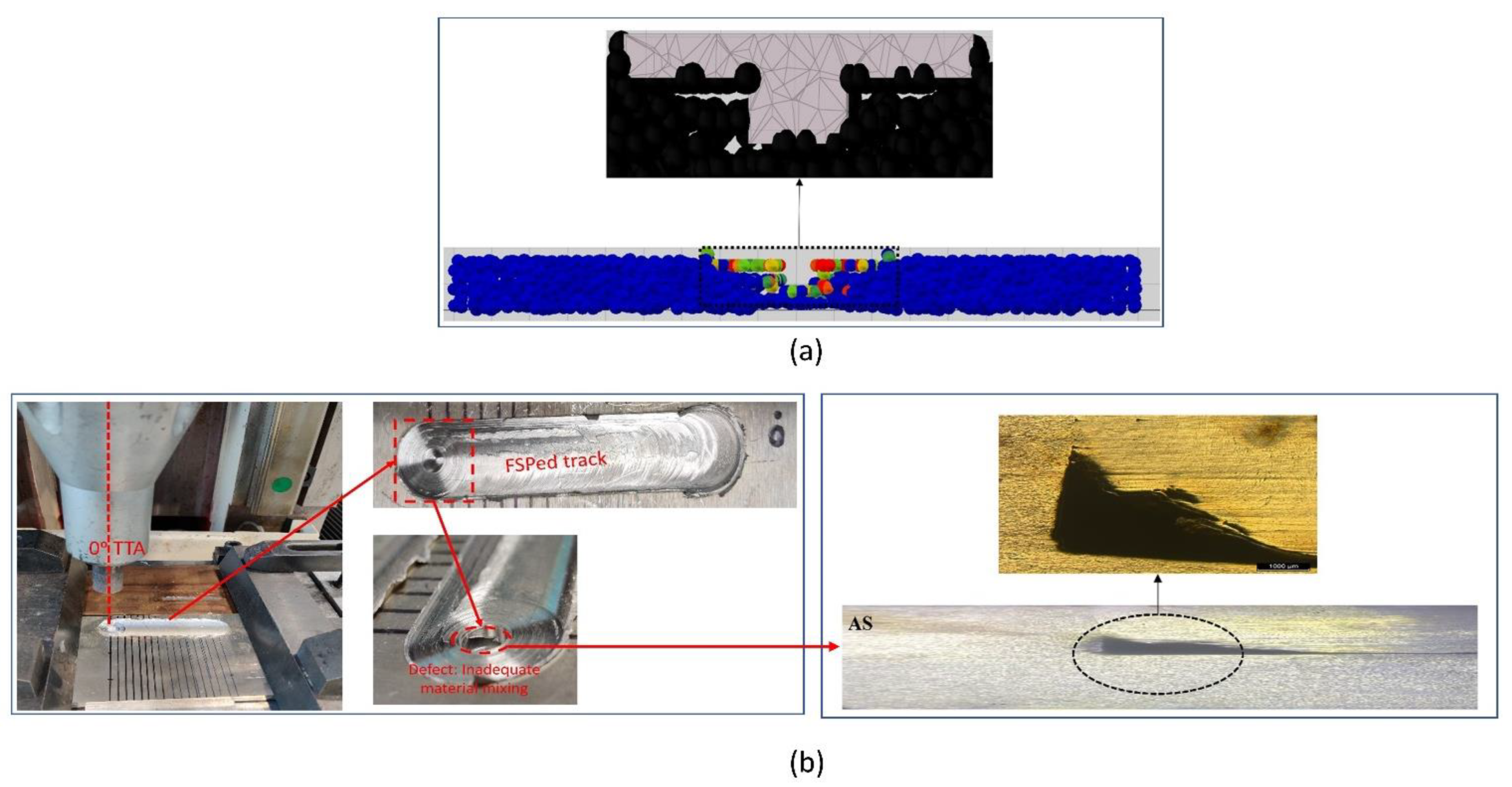
  • Simulated section cuts and experimentally acquired morphologies were verified by successfully predicting the propensity and site of the defect generation. SPH node tracking validated the incomplete node flow from RS to AS, resulting in an empty space.
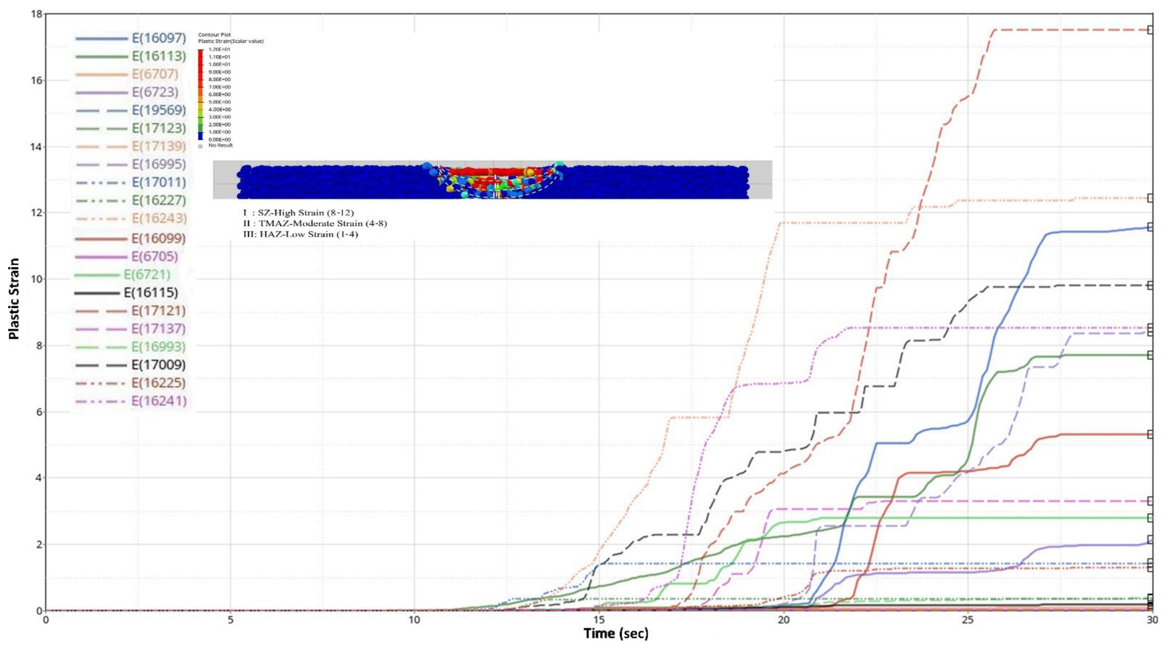
  • The high plastic strain was observed at the stir zone, whereas the moderate and low strain was observed at the thermo-mechanically affected and heat-affected zones.
  • The FSPed material exhibits a wormhole defect due to less induced pressure to fill the cavity of the pin at the rear side of the AS below the shoulder. This was also inferred from the plastic strain curve, which showed lower values for the SPH nodes 17,009 and 16,995 despite their proximity to the pin’s center, and can be considered a potential role in the defect’s origin.
Greater compressive force on the tool’s backside may boost the frictional driving force and help to diminish the wormhole flaw. This may be accomplished by giving the tool a tilt. As a result, to examine the material flow using the SPH technique, the thermo-mechanical model of FSP of AZ91 with tool tilt angle must be built. One should attempt to develop a numerical model with a bigger workpiece size that might perhaps lower the percentage error in thermal profiles. The calculation time and cost significantly increase for all three phases when conduction and convection are combined with the SPH approach. Therefore, it is advised to use high-speed computing with 96 cores or more to execute the conduction and convection using SPH. The use of a temperature-dependent coefficient of friction may improve the model’s accuracy.

Author Contributions

The research idea was perceived by R.V.M. and S.R.P., R.V.M. performed the experiment as well as numerical analysis. R.V.M. prepared the initial manuscript under the supervision of S.R.P. and T.A.L. The manuscript is reviewed and edited by S.R.P. and T.A.L. Resources and accessibility to computational lab were under the supervision of T.A.L. and S.R.P., V.S.R.J. analyzed and assisted R.V.M. in developing numerical model. All authors have read and agreed to the published version of the manuscript.

Funding

This research received no external funding.

Acknowledgments

This work was financially supported by Universiti Teknologi PETRONAS, Malaysia under Research Grant Number: YUTP-FRG 1/2021 (015LC0-347).

Conflicts of Interest

The authors declare no conflict of interest.

References

  1. Mordike, B.L.; Ebert, T. Magnesium: Properties—Applications—Potential. Mater. Sci. Eng. A 2001, 302, 37–45. [Google Scholar] [CrossRef]
  2. Blawert, C.; Hort, N.; Kainer, K. Automotive Application of Magnesium and Its Alloys. Trans. Indian Inst. Met. 2004, 57, 397–408. [Google Scholar]
  3. Easton, M.; Beer, A.; Barnett, M.; Davies, C.; Dunlop, G.; Durandet, Y.; Blacket, S.; Hilditch, T.; Beggs, P. Magnesium Alloy Applications in Automative Structures. JOM 2008, 60, 57–62. [Google Scholar] [CrossRef]
  4. Kulekci, M.K. Magnesium and Its Alloys Applications in Automotive Industry. Int. J. Adv. Manuf. Technol. 2008, 39, 851–865. [Google Scholar] [CrossRef]
  5. Mathaudhu, S.N.; Luo, A.; Neelameggham, N.R.; Nyberg, E.A.; Sillekens, W.H. Essential Readings in Magnesium Technology; Mathaudhu, S.N., Luo, A.A., Neelameggham, N.R., Nyberg, E.A., Sillekens, W.H., Eds.; Wiley: New York, NY, USA, 2014; ISBN 978-1-118-85894-3. [Google Scholar]
  6. Song, J.; She, J.; Chen, D.; Pan, F. Latest Research Advances on Magnesium and Magnesium Alloys Worldwide. J. Magnes. Alloy. 2020, 8, 1–41. [Google Scholar] [CrossRef]
  7. Singh Sidhu, H.; Singh, B.; Kumar, P. Effect of Cryogenic Treatment on Corrosion Behavior of Friction Stir Processed Magnesium Alloy AZ91. Mater. Today Proc. 2021, 46, 10389–10395. [Google Scholar] [CrossRef]
  8. Khani, S.; Aboutalebi, M.R.; Salehi, M.T.; Samim, H.R.; Palkowski, H. Microstructural Development during Equal Channel Angular Pressing of As-Cast AZ91 Alloy. Mater. Sci. Eng. A 2016, 678, 44–56. [Google Scholar] [CrossRef]
  9. Sharahi, H.J.; Pouranvari, M.; Movahedi, M. Strengthening and Ductilization Mechanisms of Friction Stir Processed Cast Mg–Al–Zn Alloy. Mater. Sci. Eng. A 2020, 781, 139249. [Google Scholar] [CrossRef]
  10. Heidarzadeh, A.; Mironov, S.; Kaibyshev, R.; Çam, G.; Simar, A.; Gerlich, A.; Khodabakhshi, F.; Mostafaei, A.; Field, D.P.; Robson, J.D.; et al. Friction Stir Welding/Processing of Metals and Alloys: A Comprehensive Review on Microstructural Evolution. Prog. Mater. Sci. 2020, 117, 100752. [Google Scholar] [CrossRef]
  11. Ritti, L.; Bhat, T. Design and Numerical Analysis of Tool for FSP Simulation of Magnesium Alloys. Mater. Today Proc. 2021, 46, 2489–2497. [Google Scholar] [CrossRef]
  12. Zhang, H.F.; Zhou, L.; Li, G.H.; Tang, Y.T.; Li, W.L.; Wang, R. Prediction and Validation of Temperature Distribution and Material Flow during Refill Friction Stir Spot Welding of AZ91D Magnesium Alloy. Sci. Technol. Weld. Join. 2021, 26, 153–160. [Google Scholar] [CrossRef]
  13. Lebaal, N.; Chamoret, D.; Schlegel, D.; Folea, M. Thermal Modelling of Friction Stir Process (FSP) and Identification Parameters. Mater. Phys. Mech. 2017, 32, 14–20. [Google Scholar]
  14. Cartigueyen, S.; Sukesh, O.P.; Mahadevan, K. Numerical and Experimental Investigations of Heat Generation during Friction Stir Processing of Copper. Procedia Eng. 2014, 97, 1069–1078. [Google Scholar] [CrossRef] [Green Version]
  15. Bagheri, B.; Abdollahzadeh, A.; Abbasi, M.; Kokabi, A.H. Effect of Vibration on Machining and Mechanical Properties of AZ91 Alloy during FSP: Modeling and Experiments. Int. J. Mater. Form. 2020, 14, 623–640. [Google Scholar] [CrossRef]
  16. Agha Amini Fashami, H.; Bani Mostafa Arab, N.; Hoseinpour Gollo, M.; Nami, B. Numerical and Experimental Investigation of Defects Formation during Friction Stir Processing on AZ91. SN Appl. Sci. 2021, 3, 108. [Google Scholar] [CrossRef]
  17. Tutunchilar, S.; Haghpanahi, M.; Besharati Givi, M.K.; Asadi, P.; Bahemmat, P. Simulation of Material Flow in Friction Stir Processing of a Cast Al-Si Alloy. Mater. Des. 2012, 40, 415–426. [Google Scholar] [CrossRef]
  18. Zinati, R.F.; Razfar, M.R. Finite Element Simulation and Experimental Investigation of Friction Stir Processing of Polyamide 6. Proc. Inst. Mech. Eng. Part B J. Eng. Manuf. 2015, 229, 2205–2215. [Google Scholar] [CrossRef]
  19. Miles, M.P.; Nelson, T.W.; Gunter, C.; Liu, F.C.; Fourment, L.; Mathis, T. Predicting Recrystallized Grain Size in Friction Stir Processed 304L Stainless Steel. J. Mater. Sci. Technol. 2019, 35, 491–498. [Google Scholar] [CrossRef]
  20. Mimouni, O.; Badji, R.; Hadji, M.; Kouadri-David, A.; Rachid, H.; Chekroun, N. Numerical Simulation of Temperature Distribution and Material Flow During Friction Stir Welding 2017A Aluminum Alloys. MS T 2019–Mater. Sci. Technol. 2019, 12002, 1034–1040. [Google Scholar] [CrossRef] [Green Version]
  21. Shamanian, M.; Mostaan, H.; Safari, M.; Dezfooli, M.S. Friction-Stir Processing of Al-12%Si Alloys: Grain Refinement, Numerical Simulation, Microstructure Evolution, Dry Sliding Wear Performance and Hardness Measurement. Metall. Res. Technol. 2017, 114, 213. [Google Scholar] [CrossRef]
  22. Mishra, R.S.; Ma, Z.Y. Friction Stir Welding and Processing. Mater. Sci. Eng. R Rep. 2005, 50, 1–78. [Google Scholar] [CrossRef]
  23. Ansari, M.A.; Behnagh, R.A. Numerical Study of Friction Stir Welding (FSW) Plunging Phase Using Smoothed Particle Hydrodynamics (SPH). Model. Simul. Mater. Sci. Eng. 2019, 27, 055006. [Google Scholar] [CrossRef]
  24. Bhojwani, S. Smoothed Particle Hydrodynamics Modeling of the Friction Stir Welding Process; The University of Texas at El Paso: El Paso, TX, USA, 2007. [Google Scholar]
  25. Timesli, A.; Zahrouni, H.; Braikat, B.; Moufki, A.; Lahmam, H. Numerical Model Based on SPH Method to Simulate Friction Stir Welding. Rev. Méc. Appl. Théor. 2011, 2, 537–546. [Google Scholar]
  26. Meyghani, B.; Awang, M.B.; Wu, C.S. Thermal Analysis of Friction Stir Processing (FSP) Using Arbitrary Lagrangian-Eulerian (ALE) and Smoothed Particle Hydrodynamics (SPH) Meshing Techniques. Materwiss. Werksttech. 2020, 51, 550–557. [Google Scholar] [CrossRef]
  27. Guanghua, Y.; Xinmin, H.; Yanqing, W.; Xingguo, Q.; Ming, Y.; Zuoming, C.; Kang, J. Effects of Heat Treatment on Mechanical Properties of H13 Steel. Met. Sci. Heat Treat. 2010, 52, 393–395. [Google Scholar] [CrossRef]
  28. Saravanan, V.; Rajakumar, S.; Banerjee, N.; Amuthakkannan, R. Effect of Shoulder Diameter to Pin Diameter Ratio on Microstructure and Mechanical Properties of Dissimilar Friction Stir Welded AA2024-T6 and AA7075-T6 Aluminum Alloy Joints. Int. J. Adv. Manuf. Technol. 2016, 87, 3637–3645. [Google Scholar] [CrossRef]
  29. Marode, R.V.; Pedapati, S.R.; Lemma, T.A. Effect of Process Parameters on AZ91/SiC Surface Composites for Lightweight E-Vehicles. In Proceedings of the 2022 7th International Conference on Electric Vehicular Technology (ICEVT), Bali, Indonesia, 14–16 September 2022; pp. 109–115. [Google Scholar]
  30. Altair University Introduction to Explicit Analysis with Radioss 2020. Available online: https://altairuniversity.com/free-ebooks/free-ebook-crash-analysis-with-radioss-a-study-guide/ (accessed on 15 July 2021).
  31. Fraser, K.; St-Georges, L.; Kiss, L.I. Prediction of Defects in a Friction Stir Welded Joint Using the Smoothed Particle Hydrodynamics Method. In Proceedings of the 7th Asia Pacific IIW International Congress, Singapore, 8–10 July 2013; pp. 474–479. [Google Scholar]
  32. Altair Radioss Smooth Particle Hydrodynamics. Available online: https://2021.help.altair.com/2021/hwsolvers/rad/topics/solvers/rad/theory_sph_c.htm (accessed on 22 September 2022).
  33. Monaghan, J.J. An Introduction to SPH. Comput. Phys. Commun. 1988, 48, 89–96. [Google Scholar] [CrossRef]
  34. Fraser, K. Robust and Efficient Meshfree Solid Thermo-Mechanics Simulation of Friction Stir Welding. 2017. Available online: https://www.researchgate.net/publication/319766764_Robust_and_Efficient_Meshfree_Solid_Thermo-Mechanics_Simulation_of_Friction_Stir_Welding?channel=doi&linkId=59bbf28aa6fdcca8e56243a7&showFulltext=true (accessed on 9 October 2021).
  35. Asadi, P.; Mahdavinejad, R.A.; Tutunchilar, S. Simulation and Experimental Investigation of FSP of AZ91 Magnesium Alloy. Mater. Sci. Eng. A 2011, 528, 6469–6477. [Google Scholar] [CrossRef]
  36. Arbegast, W.J. A Flow-Partitioned Deformation Zone Model for Defect Formation during Friction Stir Welding. Scr. Mater. 2008, 58, 372–376. [Google Scholar] [CrossRef] [Green Version]
  37. Commin, L.; Dumont, M.; Masse, J.E.; Barrallier, L. Friction Stir Welding of AZ31 Magnesium Alloy Rolled Sheets: Influence of Processing Parameters. Acta Mater. 2009, 57, 326–334. [Google Scholar] [CrossRef] [Green Version]
  38. Kumar, S.P.; Kumaran, S.; Rao, T.S. Structure-Property Correlation of Precipitation Hardened AZ91 Magnesium Alloy. Mater. Sci. Technol. 2013, 20, 835–838. [Google Scholar] [CrossRef]
  39. Schmidt, H.; Hattel, J.; Wert, J. An Analytical Model for the Heat Generation in Friction Stir Welding. Model. Simul. Mater. Sci. Eng. 2004, 12, 143–157. [Google Scholar] [CrossRef]
Figure 1. Setup of FSP.
Lubricants 10 00355 g001
Figure 2. Involved Boundary Conditions.
Lubricants 10 00355 g002
Figure 3. SPH Interpolation.
Lubricants 10 00355 g003
Figure 4. Geometries of Modelled parts.
Lubricants 10 00355 g004
Figure 5. Flow of SPH particles 1 mm below the AZ91 surface and 10 mm from the tool center.
Lubricants 10 00355 g005
Figure 6. Material flow for all three phases.
Lubricants 10 00355 g006
Figure 7. Plastic strain of nodes with respect to process time and location of nodes as displayed in Figure 5a.
Lubricants 10 00355 g007
Figure 8. Morphology of processed materials: (a) cut section from numerical model and (b) experimental assembly with processed macro-microstructure.
Lubricants 10 00355 g008
Figure 9. Vickers hardness distribution.
Lubricants 10 00355 g009
Figure 10. Temperature comparison between simulation and experiment at the end of (a) plunging, (b) dwelling of 5 s, and (c) traversing.
Lubricants 10 00355 g010aLubricants 10 00355 g010b
Figure 11. Temperature history derived from SPH nodes with respect to the distance.
Lubricants 10 00355 g011
Table 1. Process parameters used during experiments.
ParametersOpted Values
Tool Tilt Angle (TTA)
Plunging Speed40 mm/min
Tool Rotational Speed (ω)1000 rpm
Tool Traverse Speed (v)40 mm/min
Tool Dwelling time5 s
Tool Pin Length (PL)3 mm
Tool Plunge Depth (PD)3.3 mm
Axial Load4 KN
Table 2. JC constants for AZ91 [15].
ParametersABCnm ε 0 ˙
Values1643430.0210.2831.7681
Table 3. Properties of AZ91 and H13 steel [16,35].
PropertyAZ91H13
Density (g/cm3)1.817.8
Young’s Modulus (GPa)46210
Poisson’s Ratio0.330.3
Melting Temperature (K)8031700
Specific Heat (J/KgK)1050460
Thermal Conductivity (w/mK)72.724.5
Emissivity0.170.7
Table 4. Mie–Grüneisen EOS for AZ91 plates.
ParametersValue
Sound of speed (C) in m/s4520 m/s
Material Constant (S1)1.242
Material Constant (S2)0
Material Constant (S3)0
Γ0 (Gamma Coefficient)1.63
a (A Coefficient)0.33
E0 (Initial energy per unit reference volume)0
ρ0 (Reference Density) in g/cm31.81
Publisher’s Note: MDPI stays neutral with regard to jurisdictional claims in published maps and institutional affiliations.

