Thermal Fatigue Resistance Studies of Multilayer CrN and AlTiN Coatings Deposited on Plasma Nitrided H-13 Hot Work Steel


Abstract
:1. Introduction
2. Materials and Methods
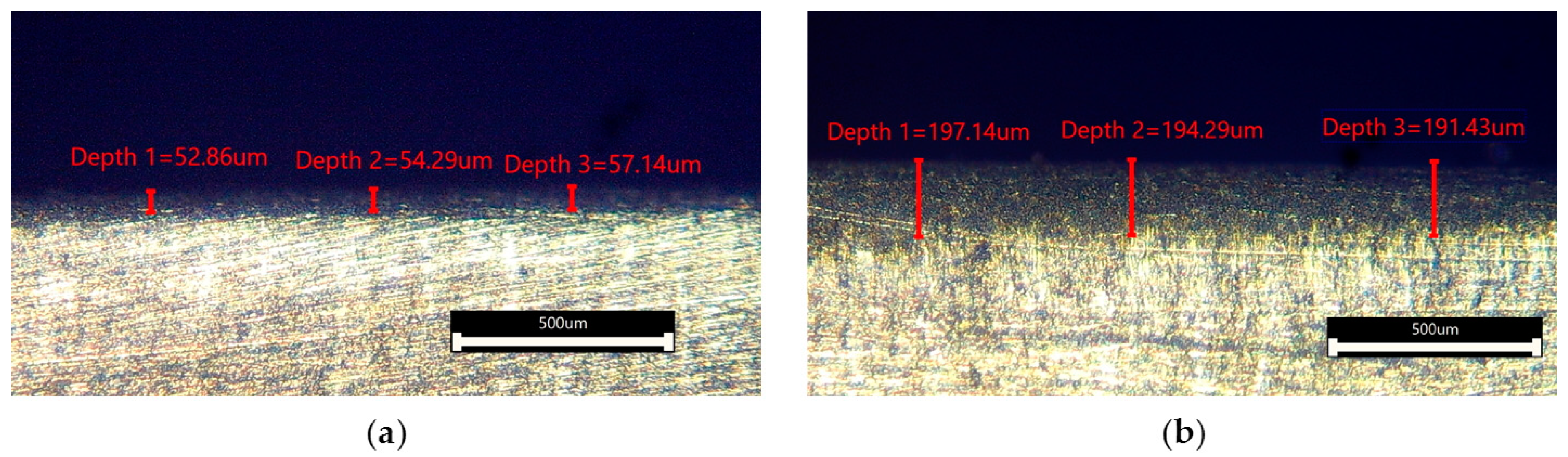
2.1. Plasma Nitrided H-13 Substrate Preparation
2.2. PVD Coating Process Details
2.3. Characterisation Details
3. Results
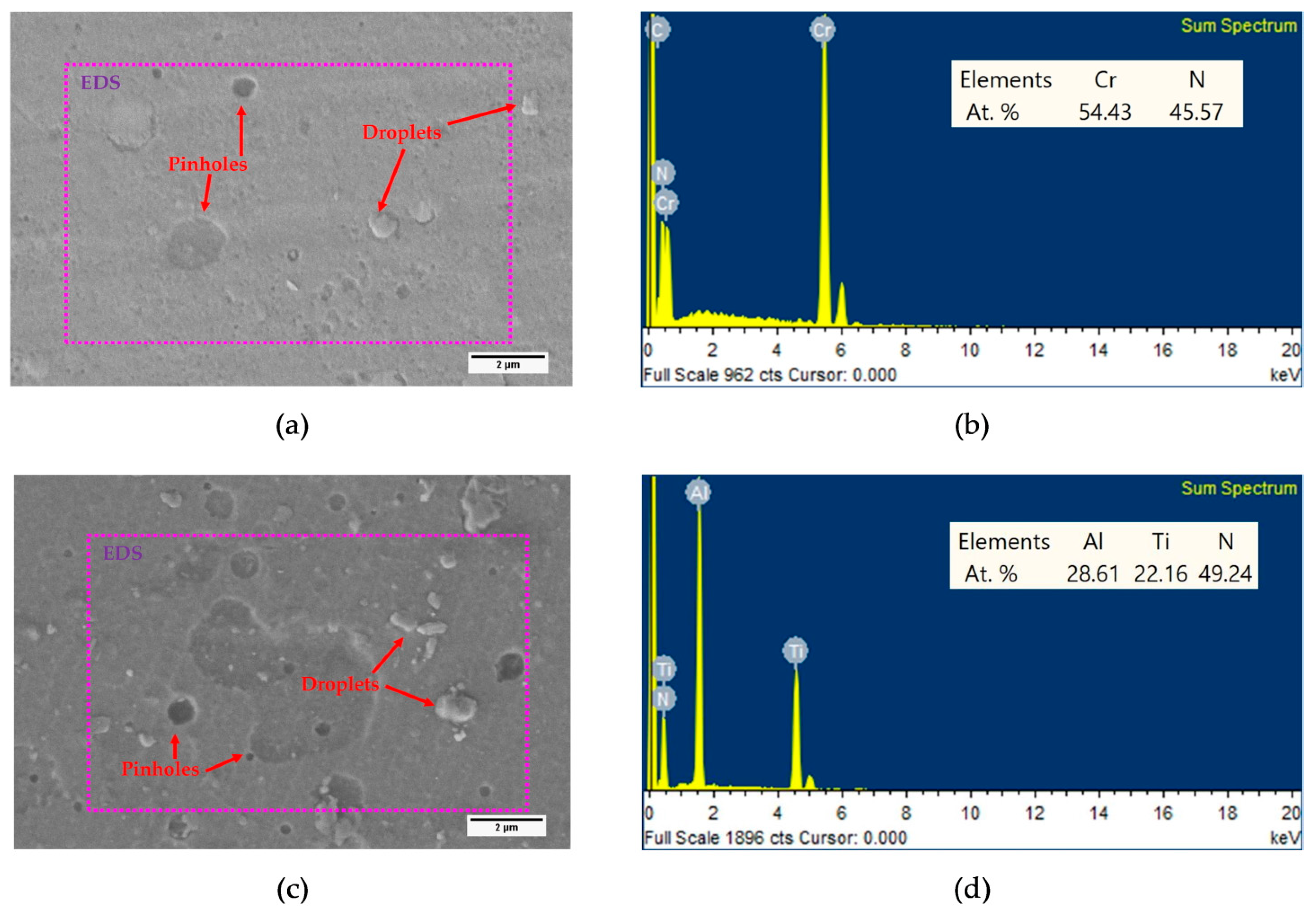
3.1. Surface Morphology and EDS Analysis
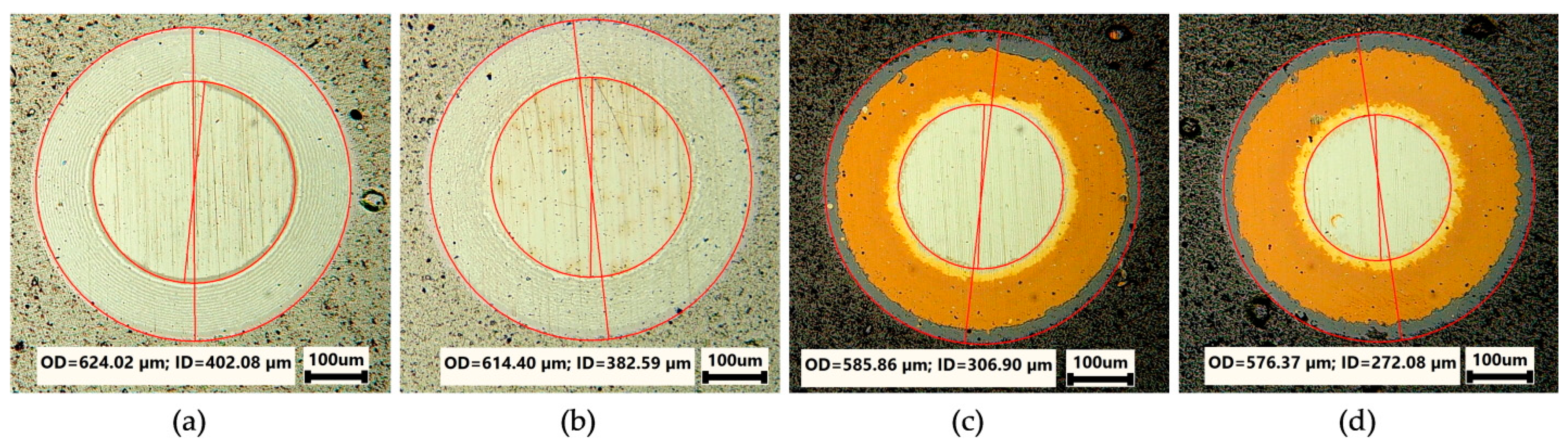
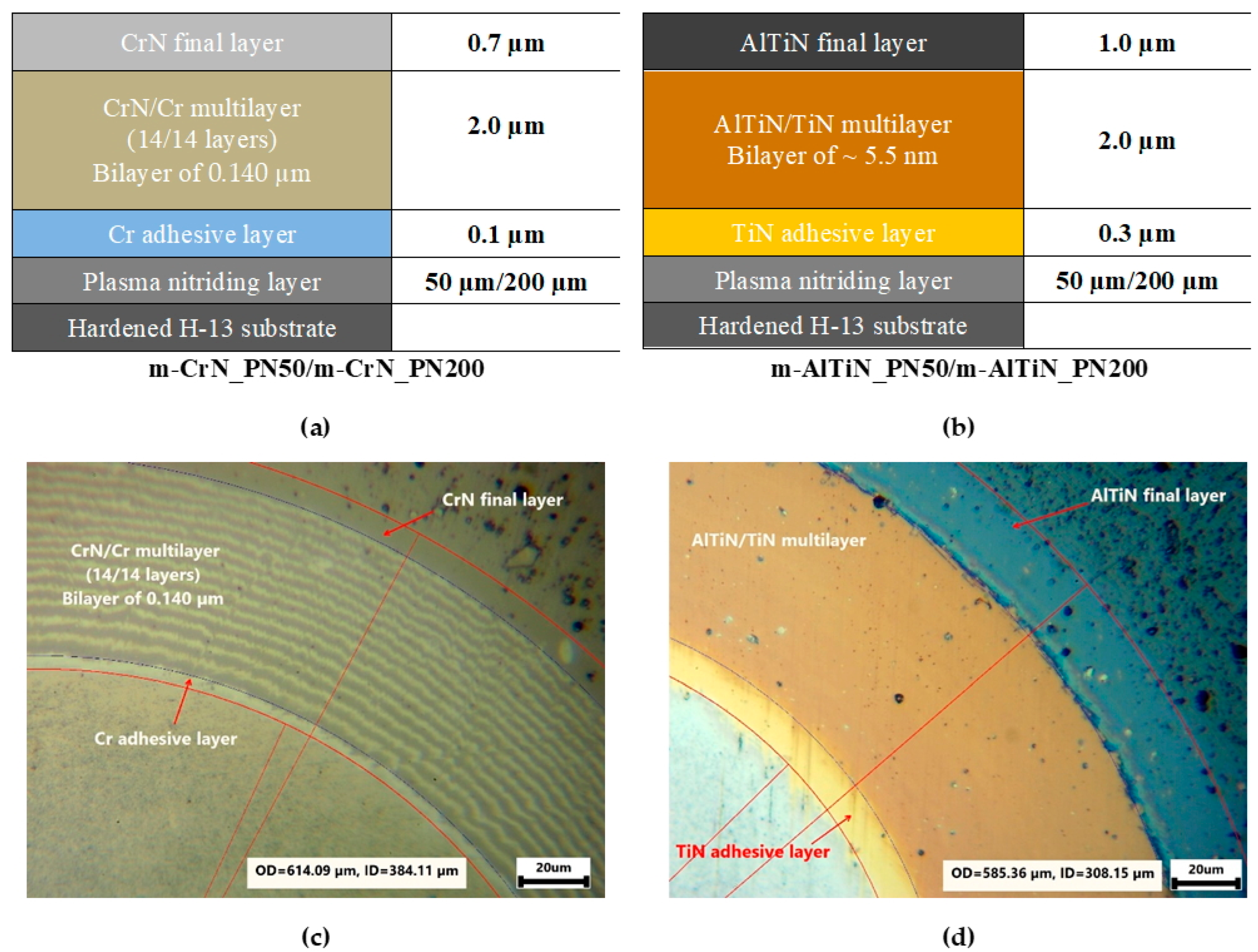
3.2. Thickness
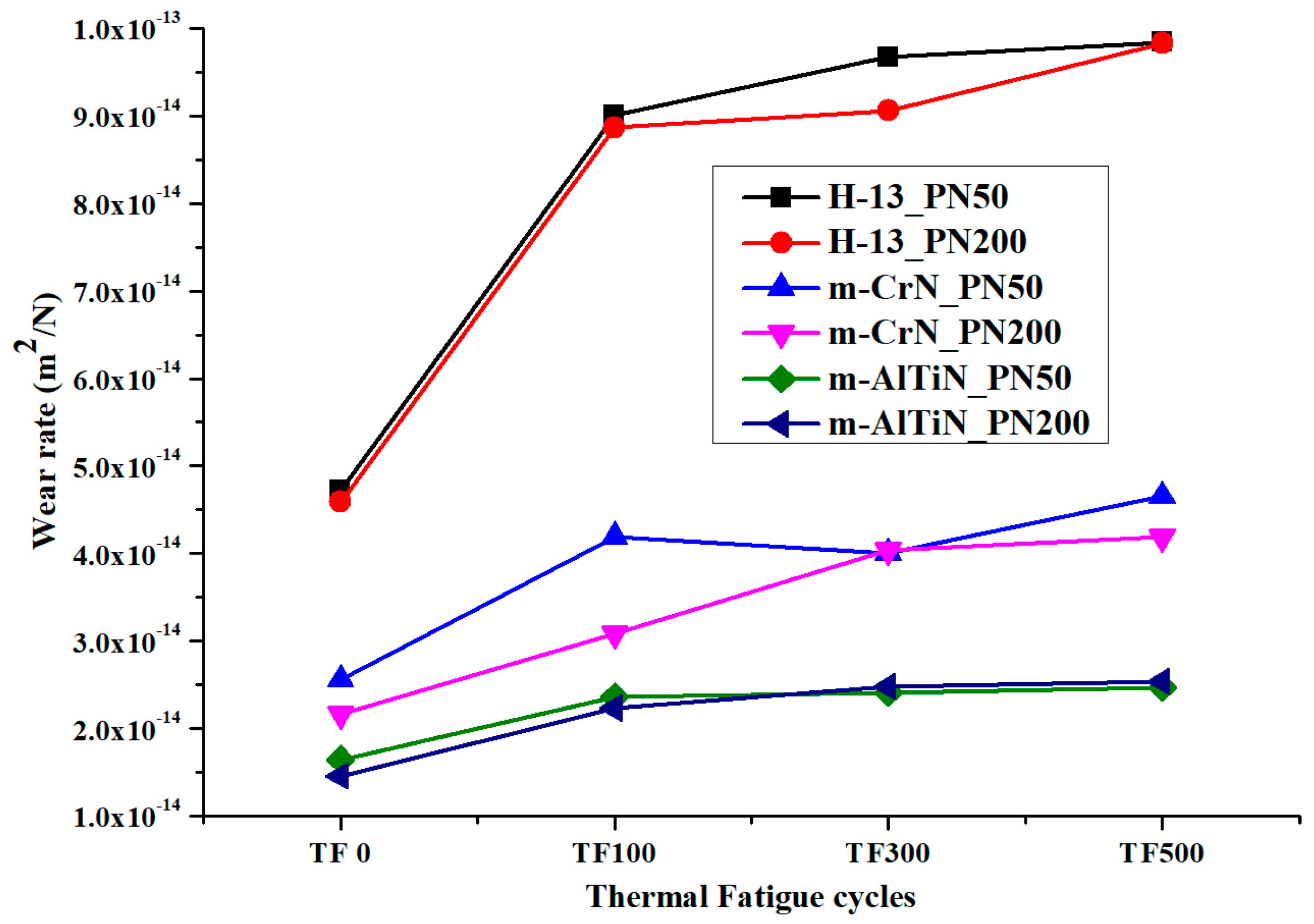
3.3. Wear
3.4. Microhardness
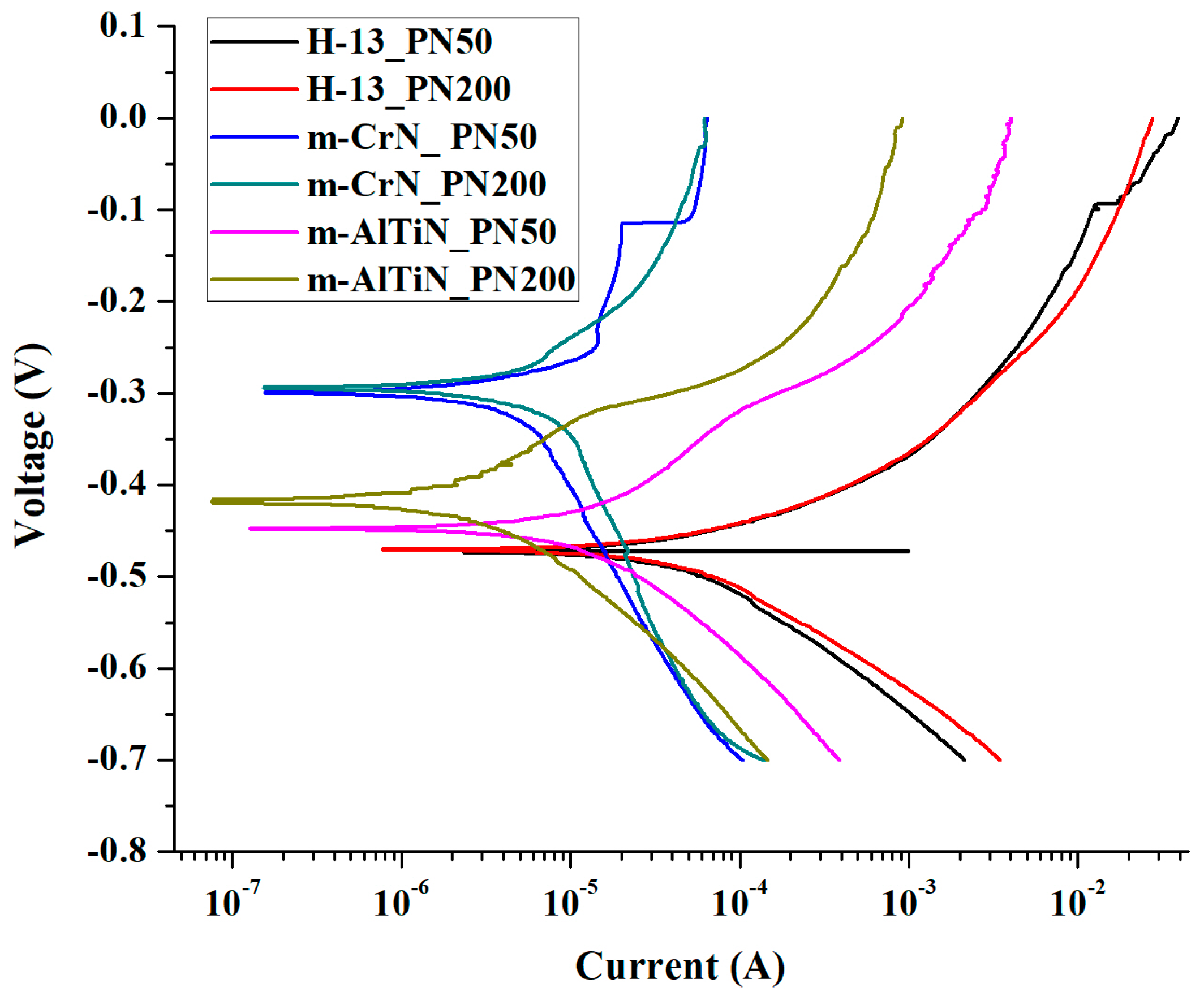
3.5. Corrosion Study
3.6. XRD Phase Analysis
3.7. Thermal Fatigue
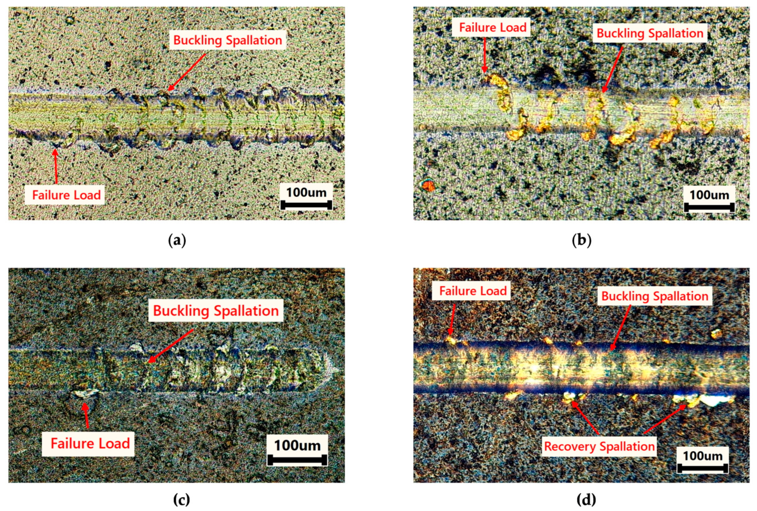
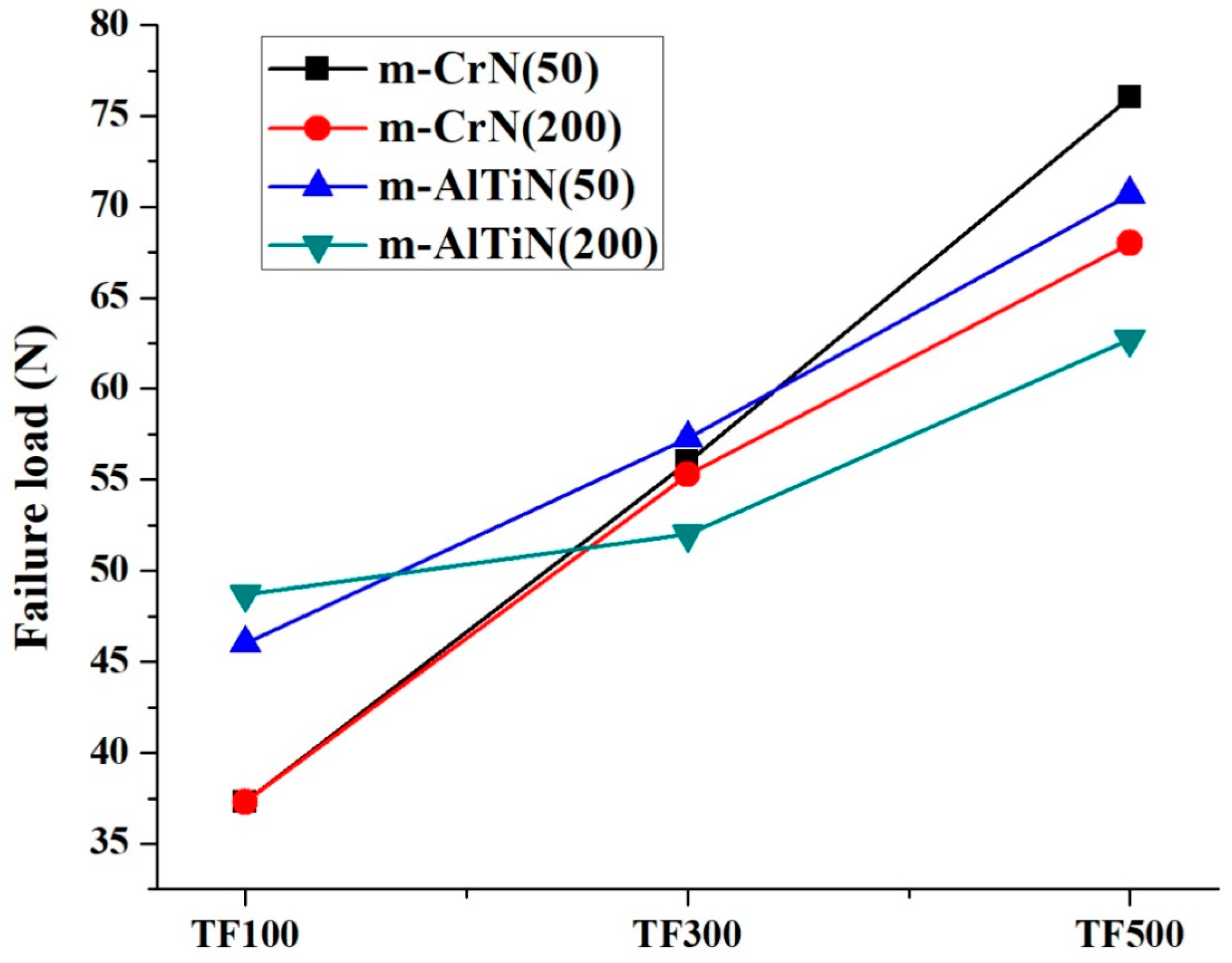
3.8. Scratch Adhesion Test
4. Discussion
5. Conclusions
Supplementary Materials
Author Contributions
Funding
Data Availability Statement
Acknowledgments
Conflicts of Interest
References
- Kovačević, L.; Terek, P.; Miletić, A.; Kukuruzović, D.; Škorić, B.; Panjan, P. Industrial Evaluation of Duplex PVD Hard Coatings for HPDC. J. Braz. Soc. Mech. Sci. Eng. 2018, 40, 271. [Google Scholar] [CrossRef]
- Mitterer, C.; Holler, F.; Üstel, F.; Heim, D. Application of Hard Coatings in Aluminium Die Casting—Soldering, Erosion and Thermal Fatigue Behaviour. Surf. Coat. Technol. 2000, 125, 233–239. [Google Scholar] [CrossRef]
- Sundqvist, M.; Hogmark, S. Effects of Liquid Aluminium on Hot-Work Tool Steel. Tribol. Int. 1993, 26, 129–134. [Google Scholar] [CrossRef]
- Liu, B.; Wang, B.; Yang, X.; Zhao, X.; Qin, M.; Gu, J. Thermal Fatigue Evaluation of AISI H13 Steels Surface Modified by Gas Nitriding with Pre- and Post-Shot Peening. Appl. Surf. Sci. 2019, 483, 45–51. [Google Scholar] [CrossRef]
- Wang, B.; Zhao, X.; Li, W.; Qin, M.; Gu, J. Effect of Nitrided-Layer Microstructure Control on Wear Behavior of AISI H13 Hot Work Die Steel. Appl. Surf. Sci. 2018, 431, 39–43. [Google Scholar] [CrossRef]
- Legg, K.O.; Graham, M.; Chang, P.; Rastagar, F.; Gonzales, A.; Sartwell, B. The Replacement of Electroplating. Surf. Coat. Technol. 1996, 81, 99–105. [Google Scholar] [CrossRef]
- Paiva, J.M.; Fox-Rabinovich, G.; Junior, E.L.; Stolf, P.; Ahmed, Y.S.; Martins, M.M.; Bork, C.; Veldhuis, S. Tribological and Wear Performance of Nanocomposite PVD Hard Coatings Deposited on Aluminum Die Casting Tool. Materials 2018, 11, 358. [Google Scholar] [CrossRef] [Green Version]
- Peng, J.; Zhu, Z.; Su, D. Sliding Wear of Nitrided and Duplex Coated H13 Steel against Aluminium Alloy. Tribol. Int. 2019, 129, 232–238. [Google Scholar] [CrossRef]
- Wang, B.; Bourne, G.R.; Korenyi-Both, A.L.; Monroe, A.K.; Midson, S.P.; Kaufman, M.J. Method to Evaluate the Adhesion Behavior of Aluminum-Based Alloys on Various Materials and Coatings for Lube-Free Die Casting. J. Mater. Process. Technol. 2016, 237, 386–393. [Google Scholar] [CrossRef]
- Li, G.; Li, X.; Wu, J. Study of the Thermal Fatigue Crack Initial Life of H13 and H21 Steels. J. Mater. Process. Technol. 1998, 74, 23–26. [Google Scholar] [CrossRef]
- Siddiqui, S.A.; Mária, M.B. Wear Behaviour of Duplex (PN+PVD) Treated Layers Produced on X42CR13 Steel. Multidiszcip. Tudományok 2019, 9, 3–11. [Google Scholar] [CrossRef] [Green Version]
- Candido Recco, A.A.; Tschiptschin, A.P. Structural and Mechanical Characterization of Duplex Multilayer Coatings Deposited onto H13 Tool Steel. J. Mater. Res. Technol. 2012, 1, 182–188. [Google Scholar] [CrossRef] [Green Version]
- Yang, S.; Cooke, K.; Sun, H.; Li, X.; Lin, K.; Dong, H. Development of Advanced Duplex Surface Systems by Combining CrAlN Multilayer Coatings with Plasma Nitrided Steel Substrates. Surf. Coat. Technol. 2013, 236, 2–7. [Google Scholar] [CrossRef]
- La Vecchia, G.M.; Lecis, N. Impact Test and Tribological Behaviour of Duplex-Treated Low-Alloy Steel. Surf. Coat. Technol. 2010, 205, 614–619. [Google Scholar] [CrossRef]
- Tillmann, W.; Vogli, E.; Momeni, S. Mechanical and Tribological Properties of Ti/TiAlN Duplex Coatings on High and Low Alloy Tool Steels. Vacuum 2009, 84, 387–392. [Google Scholar] [CrossRef]
- Batista, J.C.A.; Godoy, C.; Buono, V.T.L.; Matthews, A. Characterisation of Duplex and Non-Duplex (Ti, Al)N and Cr-N PVD Coatings. Mater. Sci. Eng. A 2002, 336, 39–51. [Google Scholar] [CrossRef]
- Batista, J.C.A.; Joseph, M.C.; Godoy, C.; Matthews, A. Micro-Abrasion Wear Testing of PVD TiN Coatings on Untreated and Plasma Nitrided AISI H13 Steel. Wear 2001, 249, 971–979. [Google Scholar] [CrossRef]
- Azzi, M.; Benkahoul, M.; Klemberg-Sapieha, J.E.; Martinu, L. Corrosion and Mechanical Properties of Duplex-Treated 301 Stainless Steel. Surf. Coat. Technol. 2010, 205, 1557–1563. [Google Scholar] [CrossRef]
- Kalss, W.; Reiter, A.; Derflinger, V.; Gey, C.; Endrino, J.L. Modern Coatings in High Performance Cutting Applications. Int. J. Refract. Met. Hard Mater. 2006, 24, 399–404. [Google Scholar] [CrossRef]
- Kale, A.N.; Ravindranath, K.; Kothari, D.C.; Raole, P.M. Tribological Properties (Ti,Al) N Coatings Deposited at Different Bias Voltage Using the Cathodic Arc Technique. Surf. Coat. Technol. 2001, 145, 60–70. [Google Scholar] [CrossRef]
- Kothari, D.C.; Kale, A.N. Recent Trends in Surface Engineering Using Cathodic Arc Technique. Surf. Coat. Technol. 2002, 158–159, 174–179. [Google Scholar] [CrossRef]
- Tien, S.K.; Duh, J.G.; Lee, J.W. Oxidation Behavior of Sputtered CrN/AlN Multilayer Coatings during Heat Treatment. Surf. Coat. Technol. 2007, 201, 5138–5142. [Google Scholar] [CrossRef]
- Kovalev, A.I.; Wainstein, D.L.; Rashkovskiy, A.Y.; Fox-Rabinovich, G.S.; Yamamoto, K.; Veldhuis, S.; Aguirre, M.; Beake, B.D. Impact of Al and Cr Alloying in TiN-Based PVD Coatings on Cutting Performance during Machining of Hard to Cut Materials. Vacuum 2009, 84, 184–187. [Google Scholar] [CrossRef]
- Polcar, T.; Martinez, R.; Vítů, T.; Kopecký, L.; Rodriguez, R.; Cavaleiro, A. High Temperature Tribology of CrN and Multilayered Cr/CrN Coatings. Surf. Coat. Technol. 2009, 203, 3254–3259. [Google Scholar] [CrossRef]
- Bouamerene, M.S.; Nouveau, C.; Aknouche, H.; Atmani, T.D.; Challali, M.O. A Study of Cr/CrN and Cr/CrN/CrAlN Multilayer Coatings for Permanent Mold Castings of Aluminum Alloys: Wear and Soldering Tendency. J. Mater. Eng. Struct. 2021, 8, 83–94. [Google Scholar]
- Chim, Y.C.; Ding, X.Z.; Zeng, X.T.; Zhang, S. Oxidation Resistance of TiN, CrN, TiAlN and CrAlN Coatings Deposited by Lateral Rotating Cathode Arc. Thin Solid Film. 2009, 517, 4845–4849. [Google Scholar] [CrossRef]
- Conde, A.; Cristóbal, A.B.; Fuentes, G.; Tate, T.; de Damborenea, J. Surface Analysis of Electrochemically Stripped CrN Coatings. Surf. Coat. Technol. 2006, 201, 3588–3595. [Google Scholar] [CrossRef] [Green Version]
- Wu, Z.T.; Qi, Z.B.; Zhu, F.P.; Liu, B.; Wang, Z.C. Influences of Y Addition on Mechanical Properties and Oxidation Resistance of CrN Coating. Phys. Procedia 2013, 50, 150–155. [Google Scholar] [CrossRef] [Green Version]
- Barshilia, H.C.; Jain, A.; Rajam, K.S. Structure, Hardness and Thermal Stability of Nanolayered TiN/CrN Multilayer Coatings. Vacuum 2003, 72, 241–248. [Google Scholar] [CrossRef]
- Thorat, N.; Mundotia, R.; Varma, R.; Kale, A.; Mhatre, U.; Patel, N. Structural & Oxidation Behavior of TiN & AlxTi1-XN Coatings Deposited by CA-PVD Technique. In AIP Conference Proceedings 2018; AIP Publishing LLC: Melville, NY, USA, 2018; Volume 1942, p. 080041. [Google Scholar] [CrossRef]
- Galindo, R.E.; Endrino, J.L.; Martínez, R.; Albella, J.M. Improving the Oxidation Resistance of AlCrN Coatings by Tailoring Chromium Out-Diffusion. Spectrochim. Acta-Part B At. Spectrosc. 2010, 65, 950–958. [Google Scholar] [CrossRef]
- Feng, Y.P.; Zhang, L.; Ke, R.X.; Wan, Q.L.; Wang, Z.; Lu, Z.H. Thermal Stability and Oxidation Behavior of AlTiN, AlCrN and AlCrSiWN Coatings. Int. J. Refract. Met. Hard Mater. 2014, 43, 241–249. [Google Scholar] [CrossRef]
- Fox-Rabinovich, G.S.; Beake, B.D.; Endrino, J.L.; Veldhuis, S.C.; Parkinson, R.; Shuster, L.S.; Migranov, M.S. Effect of Mechanical Properties Measured at Room and Elevated Temperatures on the Wear Resistance of Cutting Tools with TiAlN and AlCrN Coatings. Surf. Coat. Technol. 2006, 200, 5738–5742. [Google Scholar] [CrossRef]
- Fox-Rabinovich, G.S.; Weatherly, G.C.; Dodonov, A.I.; Kovalev, A.I.; Shuster, L.S.; Veldhuis, S.C.; Dosbaeva, G.K.; Wainstein, D.L.; Migranov, M.S. Nano-Crystalline Filtered Arc Deposited (FAD) TiAlN PVD Coatings for High-Speed Machining Applications. Surf. Coat. Technol. 2004, 177–178, 800–811. [Google Scholar] [CrossRef]
- Gaitan, G.B.; Caicedo, J.C.; Balogh, A.G.; Gottschalk, S. Cutting Tools Performance Enhancement by Using a TiN/TiAlN Multilayer Coating System. Phys. Status Solidi Curr. Top. Solid State Phys. 2007, 4, 4260–4266. [Google Scholar] [CrossRef]
- Bayón, R.; Igartua, A.; Fernández, X.; Martínez, R.; Rodríguez, R.J.; García, J.A.; de Frutos, A.; Arenas, M.A.; de Damborenea, J. Corrosion-Wear Behaviour of PVD Cr/CrN Multilayer Coatings for Gear Applications. Tribol. Int. 2009, 42, 591–599. [Google Scholar] [CrossRef] [Green Version]
- Ducros, C.; Sanchette, F. Multilayered and Nanolayered Hard Nitride Thin Films Deposited by Cathodic Arc Evaporation. Part 2: Mechanical Properties and Cutting Performances. Surf. Coat. Technol. 2006, 201, 1045–1052. [Google Scholar] [CrossRef]
- Wilczek, A.; Morgiel, J.; Rogal, Ł.; Maziarz, W.; Smolik, J. Microstructure and Wear of (CrN/CrAlN)/(CrAlN/VN) and (CrN/TiAlN)/(TiAlN/VN) Coatings for Molds Used in High Pressure Casting of Aluminum. Coatings 2020, 10, 261. [Google Scholar] [CrossRef] [Green Version]
- Deng, Y.; Tan, C.; Wang, Y.; Chen, L.; Cai, P.; Kuang, T.; Lei, S.; Zhou, K. Effects of Tailored Nitriding Layers on Comprehensive Properties of Duplex Plasma-Treated AlTiN Coatings. Ceram. Int. 2017, 43, 8721–8729. [Google Scholar] [CrossRef]
- Rousseau, A.F.; Partridge, J.G.; Mayes, E.L.H.; Toton, J.T.; Kracica, M.; McCulloch, D.G.; Doyle, E.D. Microstructural and Tribological Characterisation of a Nitriding/TiAlN PVD Coating Duplex Treatment Applied to M2 High Speed Steel Tools. Surf. Coat. Technol. 2015, 272, 403–408. [Google Scholar] [CrossRef]
- Mundotia, R.; Ghorude, T.; Kale, A.; Mhatre, U. Study of Multilayer and Multi-Component Coatings Deposited Using Cathodic Arc Technique on H-13 Hot Work Steel for Die-Casting Applications. Int. J. Nano Dimens. 2020, 11, 177–187. [Google Scholar]
- Mundotia, R.; Ghorude, T.; Kothari, D.C.C.; Kale, A.; Thorat, N. Tuning Bilayer Period of AlN/CrN Superlattice Coatings Deposited Using Cathodic Arc Technique for Superior Mechanical Properties and Thermal Stability. Appl. Surf. Sci. Adv. 2022, 7, 100205. [Google Scholar] [CrossRef]
- Rutherford, K.L.; Hutchings, I.M. A Micro-Abrasive Wear Test, with Particular Application to Coated Systems. Surf. Coat. Technol. 1996, 79, 231–239. [Google Scholar] [CrossRef]
- Pharr, G.M.; Oliver, W.C. Measurement of Thin Film Mechanical Properties Using Nanoindentation. MRS Bull. 1992, 17, 28–33. [Google Scholar] [CrossRef]
- Oliver, W.C.; Pharr, G.M. Measurement of Hardness and Elastic Modulus by Instrumented Indentation: Advances in Understanding and Refinements to Methodology. J. Mater. Res. 2004, 19, 3–20. [Google Scholar] [CrossRef]
- Oliver, W.C.; Pharr, G.M. An improved technique for determining hardness and elastic modulus using load and displacement sensing indentation experiments. J. Mater. Res. 1992, 7, 1564–1583. [Google Scholar] [CrossRef]
- Mundotia, R.; Thorat, N.J.; Kale, A.; Mhatre, U.; Kothari, D.C.; Kovacs, T.; Ghorude, T. Study of Corrosion Properties of CrN and Multilayer CrN/Cr Coating at Different Electrolyte Temperatures Deposited on Stainless Steel by Vacuum Arc Process. In AIP Conference Proceedings 2019; AIP Publishing LLC: Melville, NY, USA, 2019; Volume 2115, p. 030313. [Google Scholar]
- Abusuilik, S.B. Pre-, Intermediate, and Post-Treatment of Hard Coatings to Improve Their Performance for Forming and Cutting Tools. Surf. Coat. Technol. 2015, 284, 384–395. [Google Scholar] [CrossRef]
- Ebrahimzadeh, I.; Ashrafizadeh, F. High Temperature Wear and Frictional Properties of Duplex-Treated Tool Steel Sliding against a Two Phase Brass. Ceram. Int. 2014, 40, 16429–16439. [Google Scholar] [CrossRef]
- Bujak, J.; Walkowicz, J.; Kusiński, J. Influence of the Nitrogen Pressure on the Structure and Properties of (Ti,Al)N Coatings Deposited by Cathodic Vacuum Arc PVD Process. Surf. Coat. Technol. 2004, 180–181, 150–157. [Google Scholar] [CrossRef]
- Bonu, V.; Jeevitha, M.; Praveen Kumar, V.; Barshilia, H.C. Nanolayered Multilayer Ti/TiN Coatings: Role of Bi-Layer Thickness and Annealing on Solid Particle Erosion Behaviour at Elevated Temperature. Surf. Coat. Technol. 2019, 357, 204–211. [Google Scholar] [CrossRef]
- Teng, Y.; Guo, Y.Y.; Zhang, M.; Yang, Y.J.; Huang, Z.; Zhou, Y.W.; Wu, F.Y.; Liang, Y.S. Effect of Cr/CrN x Transition Layer on Mechanical Properties of CrN Coatings Deposited on Plasma Nitrided Austenitic Stainless Steel. Surf. Coat. Technol. 2019, 367, 100–107. [Google Scholar] [CrossRef]
- Wiecinski, P.; Smolik, J.; Garbacz, H.; Kurzydlowski, K.J. Microstructure and Mechanical Properties of Nanostructure Multilayer CrN/Cr Coatings on Titanium Alloy. Thin Solid Film. 2011, 519, 4069–4073. [Google Scholar] [CrossRef]
- Krella, A. Resistance of PVD Coatings to Erosive and Wear Processes: A Review. Coatings 2020, 10, 921. [Google Scholar] [CrossRef]
- William Grips, V.K.; Barshilia, H.C.; Selvi, V.E.; Kalavati; Rajam, K.S. Electrochemical Behavior of Single Layer CrN, TiN, TiAlN Coatings and Nanolayered TiAlN/CrN Multilayer Coatings Prepared by Reactive Direct Current Magnetron Sputtering. Thin Solid Film. 2006, 514, 204–211. [Google Scholar] [CrossRef]
- Cruz, M.R.; Nachez, L.; Gomez, B.J.; Nosei, L.; Feugeas, J.N.; Staia, M.H. Ion Nitrided AISI H13 Tool Steel Part I—Microstructural Aspects. Surf. Eng. 2006, 22, 359–366. [Google Scholar] [CrossRef]
- Bull, S.J.; Berasetegui, E.G. An Overview of the Potential of Quantitative Coating Adhesion Measurement by Scratch Testing. Tribol. Int. 2006, 39, 99–114. [Google Scholar] [CrossRef]
- Brooks, J.; Davidson, J.; Forder, S.; Münz, W.-D.; Larsson, M. A Mössbauer Spectroscopy Study of Ti–Fe Interfaces Produced by the PVD Process. Thin Solid Films 1997, 308–309, 351–357. [Google Scholar] [CrossRef]
- Salas, O.; Oseguera, J.; Garcí, N.; Figueroa, U. Nitriding of an H13 Die Steel in a Dual Plasma Reactor. J. Mater. Eng. Perform. 2001, 10, 649–655. [Google Scholar] [CrossRef]
- Ahmad, F.; Zhang, L.; Zheng, J.; Sidra, I.; Zhang, S. Characterization of AlCrN and AlCrON Coatings Deposited on Plasma Nitrided AISI H13 Steels Using Ion-Source-Enhanced Arc Ion Plating. Coatings 2020, 10, 306. [Google Scholar] [CrossRef] [Green Version]
- Navinšek, B.; Panjan, P.; Gorenjak, F. Improvement of Hot Forging Manufacturing with PVD and DUPLEX Coatings. Surf. Coat. Technol. 2001, 137, 255–264. [Google Scholar] [CrossRef]
- Soković, M.; Panjan, P.; Kirn, R. Possibilities of Improvement of Dies Casting Tools with Duplex Treatment. J. Mater. Process. Technol. 2004, 157–158, 613–616. [Google Scholar] [CrossRef]


| Sr. No | Sample Description | Sample Name | Coating Thickness (µm) | Average Roughness (µm) |
|---|---|---|---|---|
| 1 | Hardened + PN (50 µm) | H-13_PN50 | NA | 0.035 ± 0.005 |
| 2 | Hardened + PN (200 µm) | H-13_PN200 | NA | 0.040 ± 0.005 |
| 3 | Hardened + PN (50 µm) + m-CrN | m-CrN_PN50 | 2.75 | 0.10 ± 0.01 |
| 4 | Hardened + PN (200 µm) + m-CrN | m-CrN_PN200 | 2.75 | 0.14 ± 0.01 |
| 5 | Hardened + PN (50 µm) + (TiN/AlTiN) | m-AlTiN_PN50 | 3.20 | 0.17 ± 0.01 |
| 6 | Hardened + PN(200 µm) + (TiN/AlTiN) | m-AlTiN_PN200 | 3.20 | 0.19 ± 0.01 |
| Sample | Corrosion Rate (mm/yr) | Ecorr (V) | Icorr (A) |
|---|---|---|---|
| H-13 PN 50 | 7.63 × 10⁻¹ | −0.472 | 6.58 × 10⁻⁵ |
| H-13 PN200 | 7.73 × 10⁻¹ | −0.470 | 6.67 × 10⁻⁵ |
| m-CrN PN50 | 6.63 × 10⁻² | −0.299 | 5.72 × 10⁻⁶ |
| m-CrN PN200 | 7.66 × 10⁻² | −0.293 | 6.61 × 10⁻⁶ |
| m-AlTiN PN50 | 3.35 × 10⁻² | −0.437 | 2.89 × 10⁻⁶ |
| m-AlTiN PN200 | 3.08 × 10⁻² | −0.416 | 2.66 × 10⁻⁶ |
| No. | Observed 2θ° | ICSD Data | Remark | ||
|---|---|---|---|---|---|
| 2θ° | Phase (Plane) | ICSD No. | |||
| 1 | 36.45 | 36.66 | FCC TiN (111) | 381420 | |
| 2 | 37.15 | 37.31 | FCC AlTiN (111) | 804072 | |
| 3 | 37.19 | 37.57 | FCC CrN (111) | 110065 | Substrate Phases |
| 4 | 43.43 | 43.43 | Hexagonal ε-Fe2-3N (111) | 491662 | Substrate Phases |
| 5 | 43.51 | 43.35 | FCC AlTiN (200) | 804072 | |
| 6 | 43.90 | 43.77 | FCC CrN (200) | 110065 | |
| 7 | 44.72 | 44.39 | BCC Cr (110) | 060694 | |
| 8 | 63.77 | 63.59 | FCC CrN (200) | 110065 | Substrate Phases |
| 9 | 64.89 | 64.57 | BCC Cr (200) | 060694 | |
| 10 | 75.77 | 75.59 | Orthorhombic CrN (211) | 702942 | |
| 11 | 76.86 | 76.82 | Hexagonal ε-Fe2-3N (113) | 491663 | Substrate Phases |
| No. | Observed 2θ° | ICSD Data | Remark | ||
|---|---|---|---|---|---|
| 2θ° | Phase (Plane) | ICSD No. | |||
| 1 | 37.19 | 37.57 | FCC CrN (111) | 110065 | Substrate Phases |
| 2 | 43.74 | 43.77 | FCC CrN (200) | 110065 | |
| 3 | 44.41 | 43.43 | Hexagonal ε-Fe2-3N (111) | 491662 | Substrate Phases |
| 4 | 44.18 | 44.207 | Rhombohedral Cr2O3 (202) | 850869 | |
| 5 | 62.79 | 62.50 | Orthorhombic CrN (200) | 702942 | |
| 6 | 64.38 | 63.59 | FCC CrN (200) | 110065 | Substrate Phases |
| 7 | 68.50 | 68.32 | Hexagonal Cr2N (300) | 792159 | |
| 8 | 69.15 | 69.04 | Orthorhombic CrN (012) | 702942 | |
| 9 | 75.44 | 75.59 | Orthorhombic CrN (211) | 702942 | |
| 10 | 76.86 | 76.82 | Hexagonal ε-Fe2-3N (113) | 491663 | Substrate Phases |
| No. | Observed 2θ° | ICSD Data | Remark | ||
|---|---|---|---|---|---|
| 2θ° | Phase (Plane) | ICSD No. | |||
| 1 | 35.15 | 35.15 | Rhombohedral Al2O3 (104) | 821468 | |
| 2 | 36.59 | 36.60 | Orthorhombic TiO2 (200) | 841750 | |
| 3 | 37.19 | 37.57 | FCC CrN (111) | 110065 | Substrate Phases |
| 4 | 37.31 | 37.31 | FCC AlTiN (111) | 804072 | |
| 5 | 43.33 | 43.35 | FCC AlTiN (200) | 804072 | |
| 6 | 44.42 | 43.43 | Hexagonal ε-Fe2-3N (111) | 491662 | Substrate Phases |
| 7 | 64.43 | 63.59 | FCC CrN (200) | 110065 | Substrate Phases |
| 8 | 69.46 | 68.88 | Rhombohedral Al2O3 (300) | 851337 | |
| 9 | 76.86 | 76.82 | Hexagonal ε-Fe2-3N (113) | 491663 | Substrate Phases |
Disclaimer/Publisher’s Note: The statements, opinions and data contained in all publications are solely those of the individual author(s) and contributor(s) and not of MDPI and/or the editor(s). MDPI and/or the editor(s) disclaim responsibility for any injury to people or property resulting from any ideas, methods, instructions or products referred to in the content. |
© 2023 by the authors. Licensee MDPI, Basel, Switzerland. This article is an open access article distributed under the terms and conditions of the Creative Commons Attribution (CC BY) license (https://creativecommons.org/licenses/by/4.0/).
Share and Cite
Gurada, C.; Mundotia, R.; Mhatre, U.; Kale, A.; Kothari, D. Thermal Fatigue Resistance Studies of Multilayer CrN and AlTiN Coatings Deposited on Plasma Nitrided H-13 Hot Work Steel. Lubricants 2023, 11, 19. https://doi.org/10.3390/lubricants11010019
Gurada C, Mundotia R, Mhatre U, Kale A, Kothari D. Thermal Fatigue Resistance Studies of Multilayer CrN and AlTiN Coatings Deposited on Plasma Nitrided H-13 Hot Work Steel. Lubricants. 2023; 11(1):19. https://doi.org/10.3390/lubricants11010019
Chicago/Turabian StyleGurada, Chetan, Rajesh Mundotia, Umesh Mhatre, Ashwin Kale, and Dushyant Kothari. 2023. "Thermal Fatigue Resistance Studies of Multilayer CrN and AlTiN Coatings Deposited on Plasma Nitrided H-13 Hot Work Steel" Lubricants 11, no. 1: 19. https://doi.org/10.3390/lubricants11010019