Article

An Analysis of Reaction Forces in Crankshaft Support Systems

by
Krzysztof Nozdrzykowski
1,*,
Zenon Grządziel
1,
Rafał Grzejda
2,
Mariusz Warzecha
3 and
Mateusz Stępień
4
1
Faculty of Marine Engineering, Maritime University of Szczecin, 1-2 Wały Chrobrego St., 70-500 Szczecin, Poland
2
Faculty of Mechanical Engineering and Mechatronics, West Pomeranian University of Technology in Szczecin, 19 Piastow Ave., 70-310 Szczecin, Poland
3
Faculty of Mechanical Engineering and Robotics, AGH University of Science and Technology, 30 Mickiewicza Ave., 30-059 Krakow, Poland
4
Piping Company, Chemar Rurociągi Sp. z. o. o., 6 Olszewskiego St., 25-663 Kielce, Poland
*
Author to whom correspondence should be addressed.
Lubricants 2022, 10(7), 151; https://doi.org/10.3390/lubricants10070151
Submission received: 30 May 2022 / Revised: 28 June 2022 / Accepted: 8 July 2022 / Published: 11 July 2022
(This article belongs to the Special Issue Rolling Contact Fatigue and White Etching Cracks of Bearings)

Abstract

:
During measurements, the crankshafts of marine engines are usually supported on a set of rigid prisms. Such prisms maintain a constant height position, cause different values of reaction forces and, consequently, may cause elastic deformations of the crankshafts. Thus, the measurements of the dimensions and geometry of the crankshaft may be distorted. This article proposes a measuring system developed to support the crankshaft with a set of flexible supports. These supports implemented the given reaction forces, which ensured the elimination of the crankshaft deformations, regardless of the possible deviations, i.e., in the coaxiality of the main crankshaft journals. The values of these forces were calculated using the finite element method (FEM). These calculations showed that in order to eliminate the crankshaft deformations, the values of the reaction forces must change not only on individual supports, but also with the change of the shaft rotation angle during the measurement. The numerical experiments showed that the application of flexible supports results in uniform contact reaction forces on adjacent main journal supports. This uniformity occurs regardless of the quality of the crankshaft geometry. Thus, the necessity to use a set of flexible supports for measuring marine engine crankshafts was confirmed. The research also showed that the values of the reaction forces ensuring the elimination of shaft deflections under the assumption of nodal support can be treated as corresponding to the resultant reaction forces realized by the prismatic heads.

1. Introduction

A specific group of elements found in machine design are crankshafts of marine engines. This specificity results from large dimensions that distinguish them from other crankshafts [1,2]. When characterizing the large-sized crankshafts, it should be emphasized that these are components with large weights and dimensions, and at the same time variable rigidity, which makes them susceptible to bending deformations [3,4,5]. Such crankshafts have small cross-sectional dimensions in relation to their length and a number of additional design details that differ from simple shafts [6,7]. Owing to the variable stiffness and bendability of the shafts, the deformations should be expected not only in the vertical direction, but also in the horizontal direction during their rotation.
In relation to this group of machine elements, high criteria are imposed on the accuracy of the geometric manufacturing, given in the product specification [8]. For this reason, the current technological process requires constant quality control of the manufactured surfaces [9]. The actual state of the geometric condition of the product can be guaranteed fully and consistently only with the use of measurement methods and techniques that enable their correct metrological implementation and equipment adapted to the required tolerances provided in the specification [10,11,12].
Fixing parts in prisms is the most common method used in the case of large cylindrical machine elements due to the simplicity of design and manufacturing of prisms, the possibility of carrying significant loads and the possibility to rotate the parts in them during the measurements, especially in the case of the so-called roll prisms [13,14]. Hence, measurements of the geometric properties of the large-size crankshafts are usually carried out with the crankshaft axis located in the horizontal plane, with a multipoint support on the main journals with a set of prism supports.
According to the results of research presented so far, the prism support can ensure complete elimination of elastic deformation of the crankshaft, provided that the supports realize variable reaction forces, the values of which should change not only along the shaft length, but also depend on its angle of rotation on the supports [8,15,16]. Taking these recommendations into account requires the use of a controlled (active) way of realizing the support reaction forces.
Uncontrolled support conditions are a source of errors that distort measurements of the geometric features, especially geometry deviations and alignment of the main and crank journals. Most measurements require that the shaft is rotated during their execution. In this case, the possibilities of supporting the crankshafts are significantly limited and depend on the design of the shafts, i.e., the number and arrangement of their main journals.
The design details of the crankshafts for engines with similar parameters (high speed, medium speed and low speed engines) may differ substantially from each other both in terms of the shape and arrangement of crank journals and the dimensions. Consequently, they have a direct influence on the weigh change of the crankshaft and, as a result, on the values of the reaction forces ensuring zero deformation values on the supported main journals.
The finite element method (FEM) [17,18] is currently the most frequently method used for various analyses of crankshafts. Jiménez Espadafor et al. [19] analyzed failure of a diesel generator crankshaft by using the FE model in which each journal was supported by a bearing that allowed free rotation. To consider the proper reaction when the forces applied to each crank journal were considered, the journal and the bearing were linked through nonlinear gap elements. The same approach was used in Ref. [20]. Sun et al. [21] conducted a three-dimensional finite element method simulation and optimization of the shrink-fitting process for a large marine crankshaft. The study did not analyze the shaft restraint in the bearings. In some studies, only a fragment of the shaft was analyzed [22,23,24,25].
In this research report, FEM was implemented to determine the values of the reaction forces ensuring zero deformations on the main journals when changing the crankshaft rotation angle. The calculations were carried out for the research object, which was the crankshaft of the eight-cylinder medium-speed main propulsion engine in the ship Buckau Wolf R8DV 136, with the support of its main journals by the concentrated forces.

2. Materials and Methods

The basic technical data of the adopted test object are summarized in Table 1.
The FEM model with the applied boundary conditions for the support of the crankshaft by the concentrated forces, applied to the nodes located at the half-length of the main journals, is shown in Figure 1. Two FEM programs, Midas NFX 2020 and PrePoMax, were used for the calculations in this stage. For the model developed in Midas NFX 2020, 137,475 CTETRA-type tetragonal finite elements were used, which were connected by 42,038 nodes. For the model developed in PrePoMax, 250,936 C3D4 tetragonal finite elements were used, which were connected by 50,742 nodes. The model was constrained and loaded as shown in Figure 1. On the right side of the model (behind journal No. 10), a reference point was introduced into the model with which the displacements and rotations about the X-axis were fixed. Further, the constraints shown on the main pivots fix the displacements in the vertical direction (Y-axis direction). It was also assumed that the last journal (counting from the camshaft sprocket side) would be supported by a constraint that fixes displacements in all three axes in order to eliminate unwanted displacements. The test subject was only loaded with the self-weight of 9300 N.
For the selected angular position of the shaft, Figure 2 shows the values of the reaction forces ensuring the elimination of the deformations on the individual main journals in the case of nodal support (concentrated forces).
As shown, the values of the reaction forces exhibit a variation along the length of the crankshaft. However, the values of the reaction forces show the variation not only along the length of the crankshaft but also as a function of the angle of rotation of the crankshaft on the supports. The nature of the variation in the values of the reaction forces within the range of the full angle of rotation of the shaft (0 ÷ 360°) is shown in Figure 3.
According to the assumptions, the resultant reaction forces correspond to the vertical components. Based on the abovementioned FEM programs, the values of the reaction forces were calculated to ensure the elimination of the deformations on individual main journals, for the angular position of the crankshaft assumed as the initial one (Figure 4).
The relative error between the results obtained for the two programs was very low and amounted to approximately 5%.

3. Results

The demonstrated variability of the reaction forces suggested that the assumption of the nodal support in calculating the values of the reaction forces ensuring the elimination of the crankshaft deformations may not be valid in the case of the prism support. This conclusion led the authors to the verification of the assumption adopted in this case, which predicted the treatment of the calculated values of the reaction forces as corresponding to the resultant reaction forces realized by the roller heads of the prism supports.
To realize the stated goal of the research, the crankshaft was modeled with a set of roller prism support heads.
The modeling was carried out using two FEA calculation programs: Midas NFX 2020 and Solid Works Simulation. In the case of the Solid Works Simulation, 1,145,408 tetragonal finite elements connected by 745,328 nodes were used to model the crankshaft. The very large number of finite elements used resulted from the need for a very dense mesh in the contact zone between the rollers and the main journals of the crankshaft. A very dense mesh was required for the correct behavior of the contact areas in the performed analysis. The simulation studies were carried out assuming the boundary conditions corresponded to the roller support referred to as “rigid” and so-called “compliant”. The “rigid” support simulated the conditions of supporting the crankshaft by means of supports, whose prismatic heads, due to the impossibility of realizing most of the degrees of freedom, limited the displacements of journals in the perpendicular (Z) and horizontal (Y) directions to the shaft axis (X). The “compliant” support, on the other hand, corresponded to the support of the crankshaft by the set of supports, the prismatic heads of which limited the possibility of displacements of journals only in the direction perpendicular (Z) to the shaft axis (X). The FE model made in the Solid Works Simulation program with the assumed boundary conditions for the support of the crankshaft by the roller prisms is shown in Figure 5.
For the selected angular position of the shaft, Figure 6a shows the distribution of the resultant reaction forces at the contact of the rolling rolls of the prism supports with the main journals of the crankshaft not affected by the deviations of the axis position for the case of “rigid” support. Figure 6b,c, respectively, show for this case the values of the vertical and horizontal components of the resultant reaction forces at the adjacent rollers of the prism heads.
A similar pattern of the changes in the reaction forces was found in the simulation tests carried out for the “compliant” support variant of the crankshaft without the deviations in the coaxiality of the main journal axes. This similarity can be seen in Figure 7a, which shows the distribution of the resultant reaction forces at the contact of rollers of the rolling prisms with the main journals of the shaft calculated with the use of Midas FX 2020 software for the selected angular position of the shaft. Accordingly, for this case, Figure 7b,c show the values of the vertical and horizontal components of the resultant reaction forces at the adjacent rollers of the prism heads.
The agreement between the calculations performed by the two calculation programs was almost one hundred percent, as can be seen in Figure 8. This applies both to the values of the resultant reaction forces on the adjacent rolls of the prism heads (Figure 8a) and the total resultant reaction forces (Figure 8b).
The conducted research for the case of the shaft subject to the axis misalignment showed that with the use of the “rigid” roller support, the values of the resultant reaction forces on the adjacent rolls of the prism heads differed significantly. This is shown in Figure 9a, which presents the distribution of the resultant reaction forces on the rolls for the case of the introduced misalignment of one of the main journals. The values of the vertical and horizontal components of the resultant reaction forces on the adjacent rolls of the prism heads are shown in Figure 9b,c.
The introduced deviation of the main crankshaft journal No. 5 axis position was 0.03 mm. As the result, during the crankshaft rotation the axis of this journal exhibited an eccentric movement with respect to the main axis of the crankshaft. This results in generating variable values of the reaction forces on the rollers of the prism heads. The use of the “compliant” support, on the other hand, ensures identical reaction forces on the adjacent rollers of the prism heads. The values of these forces were the same as in the case of the “rigid” or “compliant” support of the crankshaft, not affected by the deviations in the main journal axes.

4. Discussion

This paper is a continuation of research related to the practical implementation of the developed measuring system equipped with the so-called “compliant” system of supporting the measured object, especially large-size crankshafts [10,14]. The need to create the system was demonstrated by the necessity of implementing variable reaction forces during measurements of geometric deviations of crankshafts. The implementation of variable support reaction forces ensures the elimination of the elastic deformation of the crankshafts, which distorts the measurements of the geometric quantities. This fact has also been verified experimentally in previous works [5,26]. As emphasized at the beginning of this paper, observations made during earlier research suggested that the implementation of the variable reaction forces could result in different values of the reaction forces on the rollers of the prism heads that support the crankshaft compliant support system. This suggestion contradicted the initial assumption that the resultant reaction forces on the supports are aligned vertically.
This suggestion was verified by the simulation studies, exemplary results of which were presented in this paper. The results of the study carried out using two different FE simulation programs showed unambiguously that regardless of the geometric condition of the crankshaft, the use of flexible support ensures uniform values of the reaction forces on the adjacent rolls of the prism supports. This confirmed the possibility of treating the resultant support reaction forces as corresponding to the concentrated reaction forces calculated earlier by FEM. These tests also showed that, in the case of the crankshaft subject to axial misalignment, supporting the main journals with a set of rigid prism supports results in significant differences in the support reaction forces on the adjacent prism head rolls. Thus, demonstrating once again the significant advantages of the proposed “compliant” support over the traditional one, where the crankshaft is seated on a set of prism supports that maintains a constant height position during measurements.
FEM analyses using the model presented in the paper are of great importance for assessing the condition of the entire crank–piston system, and in particular the hydrodynamically lubricated slide bearings [27].
Experimental studies, together with their evaluation and statistical validation, were presented in our previous reports promoting the advantages of using “compliant” support for the measurement of crankshafts. These tests were carried out for various variants of fixing the crankshaft. The first option envisaged fixing the crankshaft with external main journals in the prism and supporting it in the middle part with a set of flexible supports. This variant corresponded to the conditions of the so-called reference measurements. For this variant of the crankshaft restraint, the results of the experimental tests are presented in [28,29]. Another variant of fixing the crankshaft supported by a set of compliant supports was the variant with the fixing of the crankshaft with outer end faces in spherical centers. This variant corresponded to the conditions of the so-called nonreference measurements. The results of these experimental tests and their evaluation are presented in [30,31]. Currently, studies are conducted for the case of supporting the crankshaft by means of a set of compliant supports located at the same height. Partial results of these experimental studies are presented in [14]. Another paper is being prepared, which is related to the subject of crankshaft measurements in conditions limiting the possibility of detecting its geometric deviations caused by the adopted conditions of support and the use of supports equipped with compliant prism heads.

5. Conclusions

Based on the obtained test results, the following conclusions can be drawn:
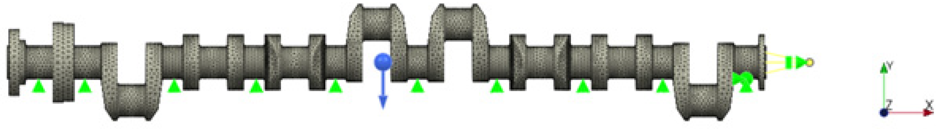
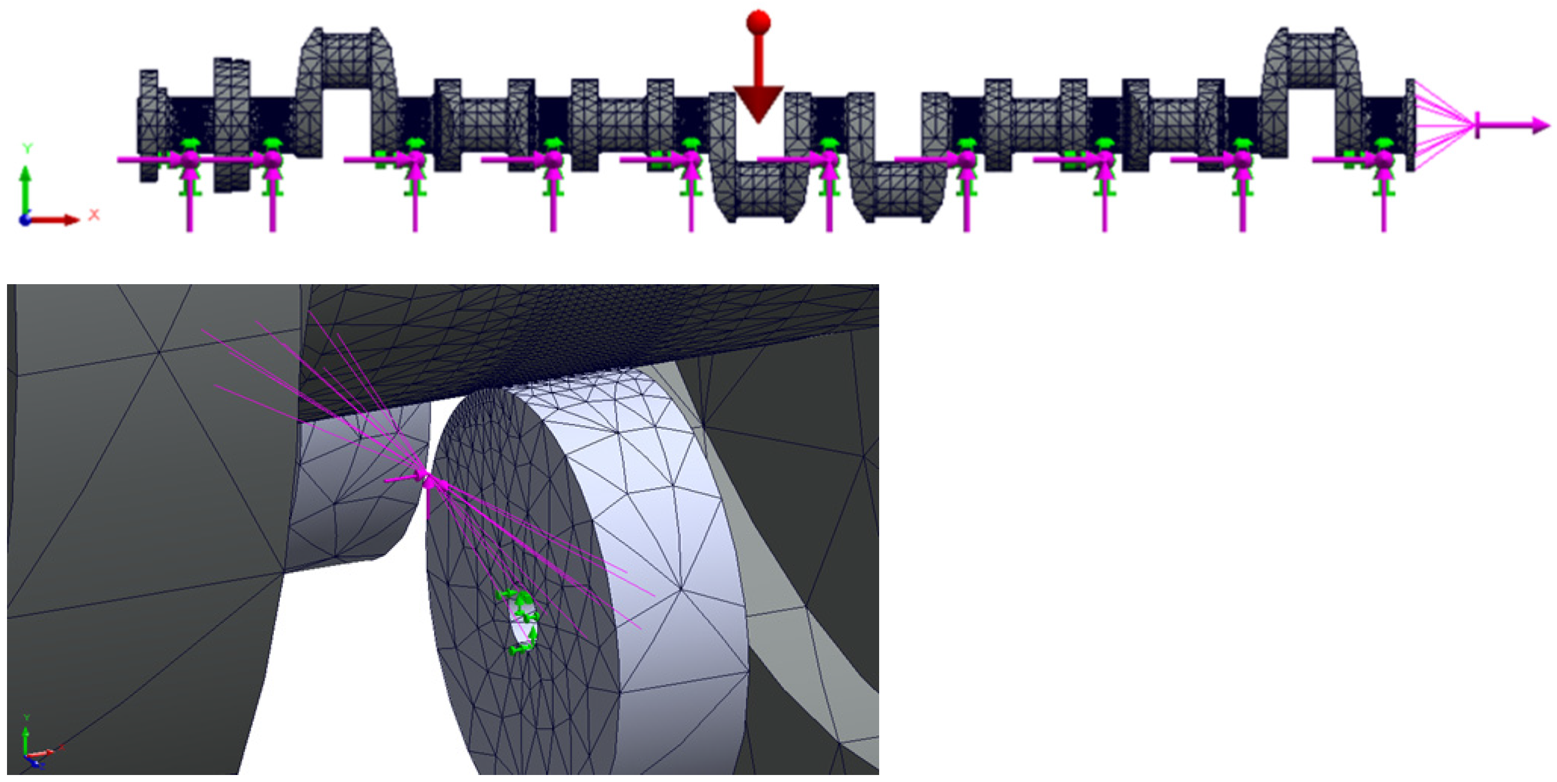
  • To enable correct measurements of the geometric deviations of the crankshafts, it is necessary to support their main journals with a set of supports whose prism heads do not restrict the displacements of the journals subjected to axial position errors.
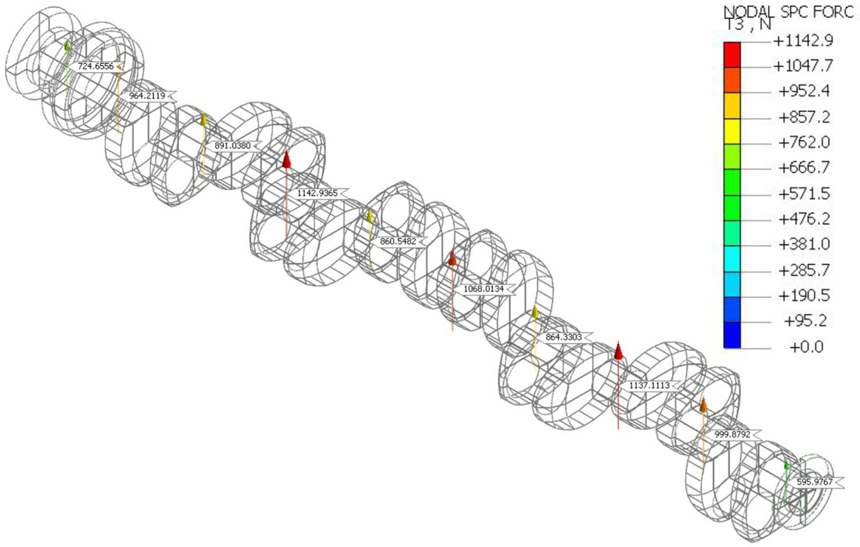
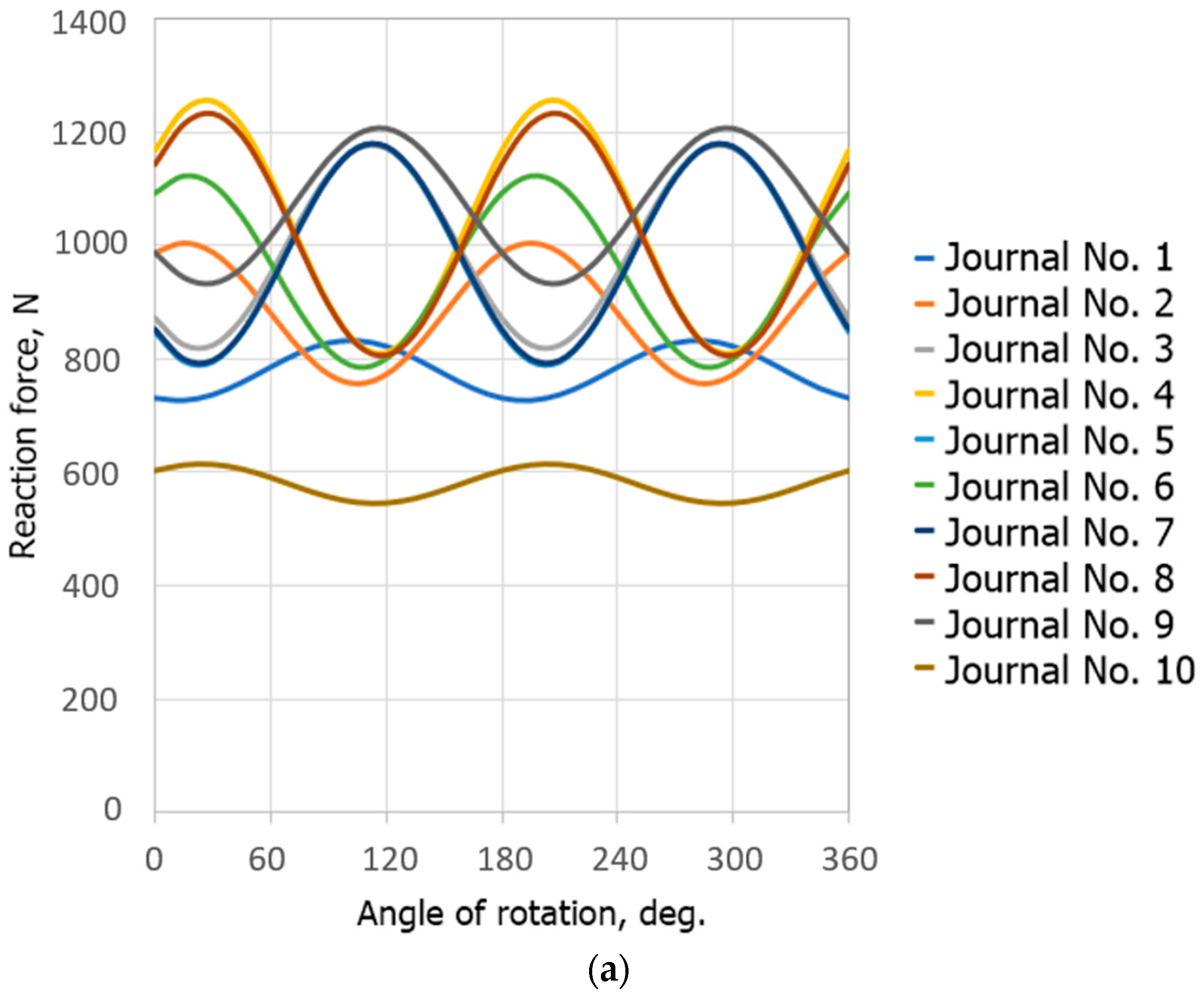
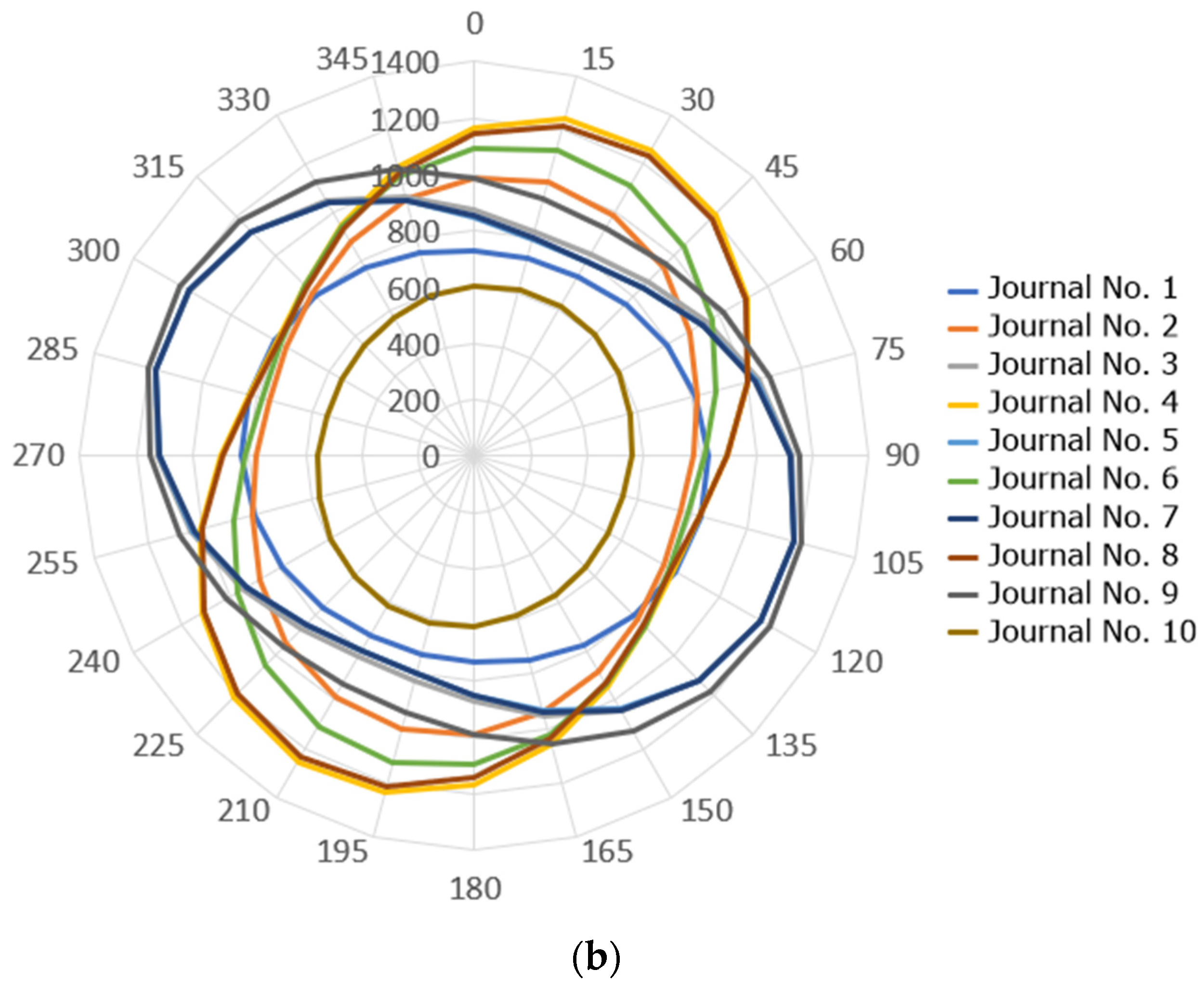
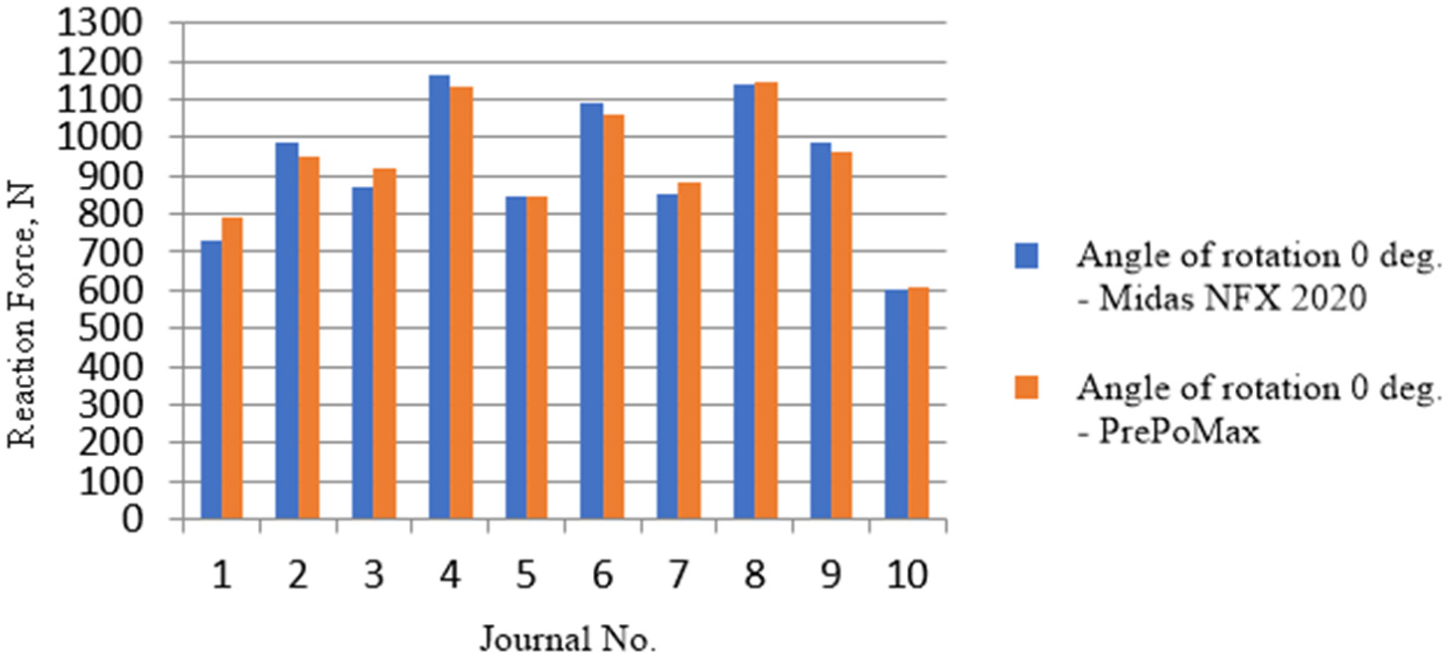
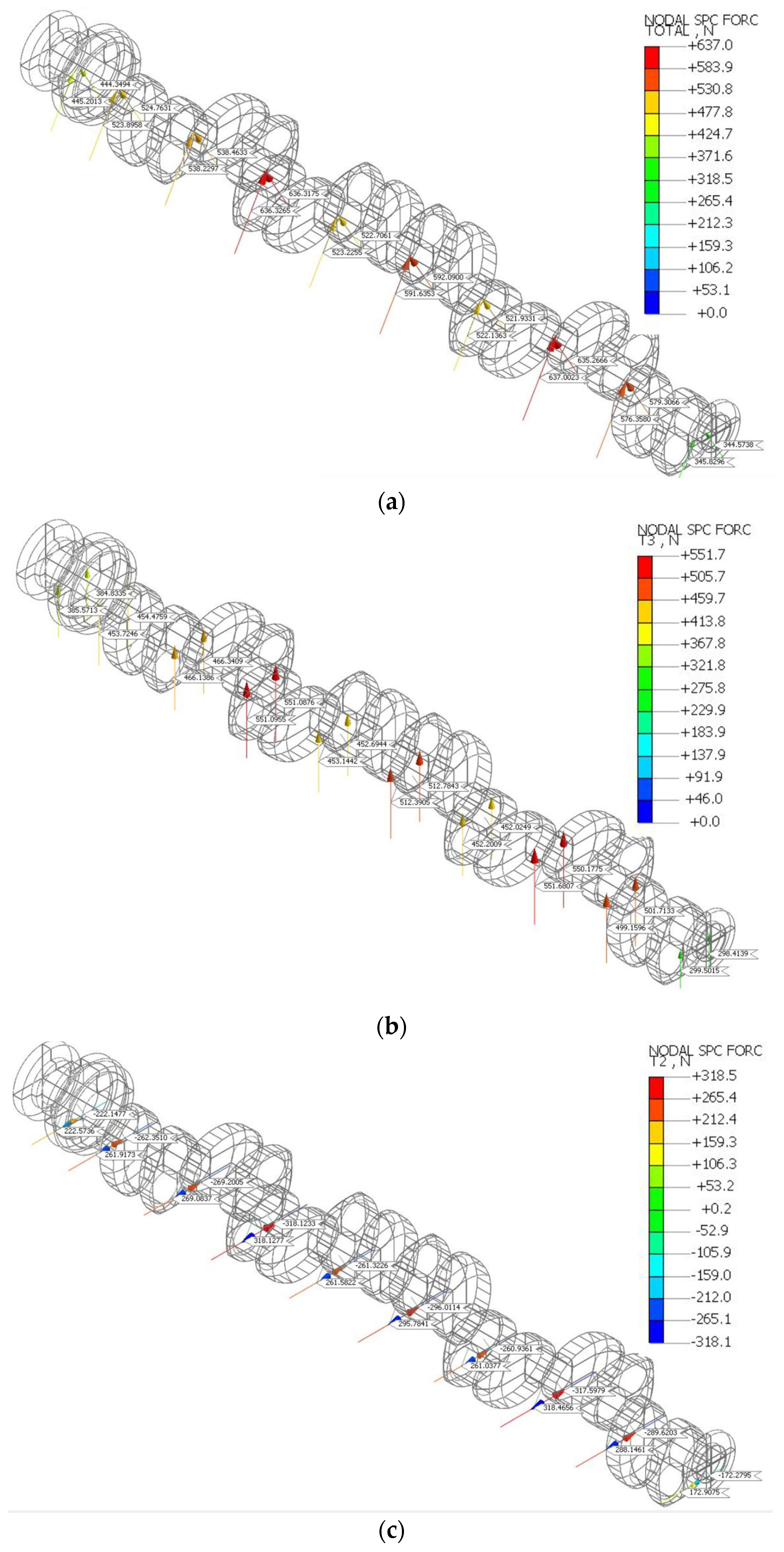
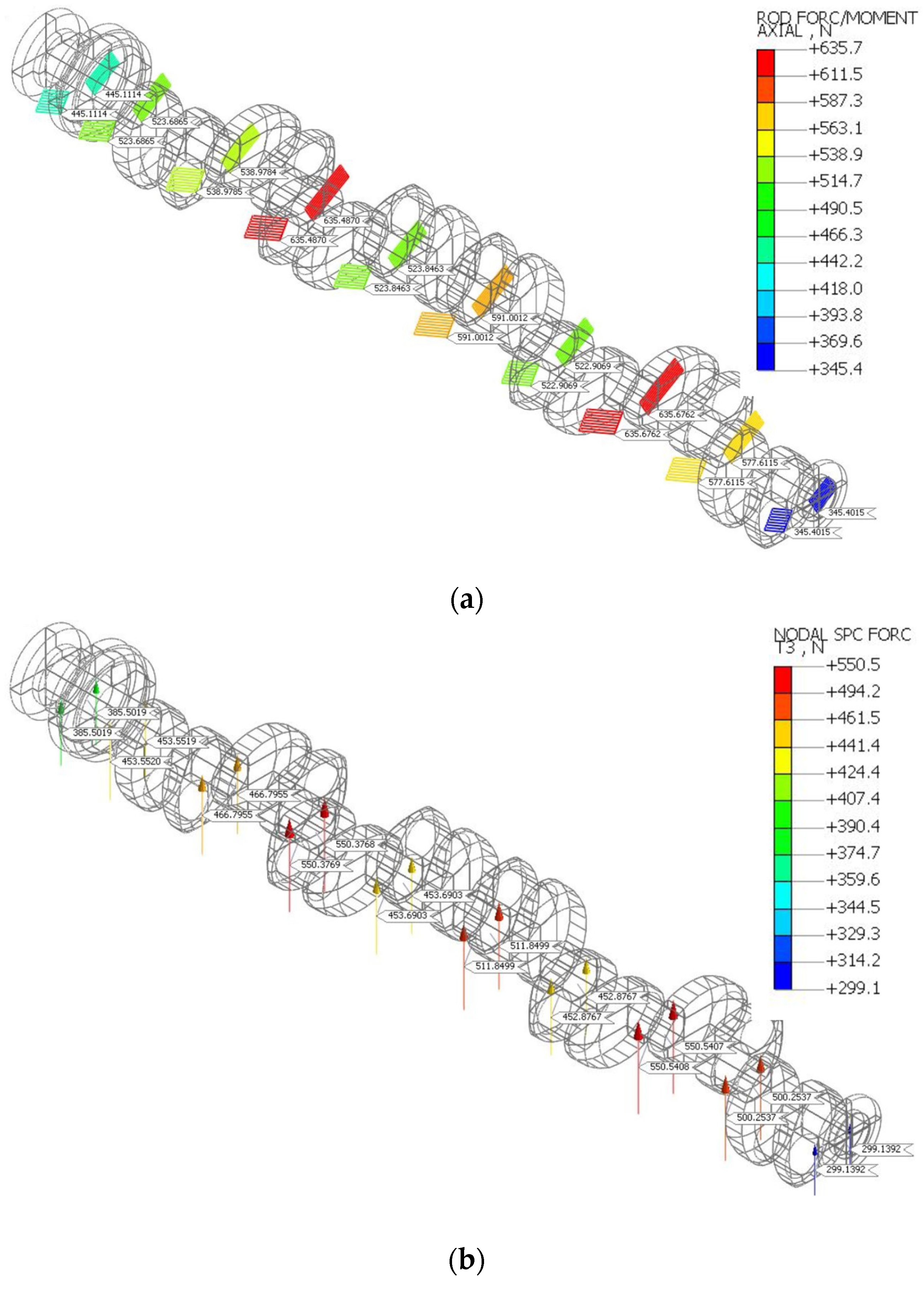
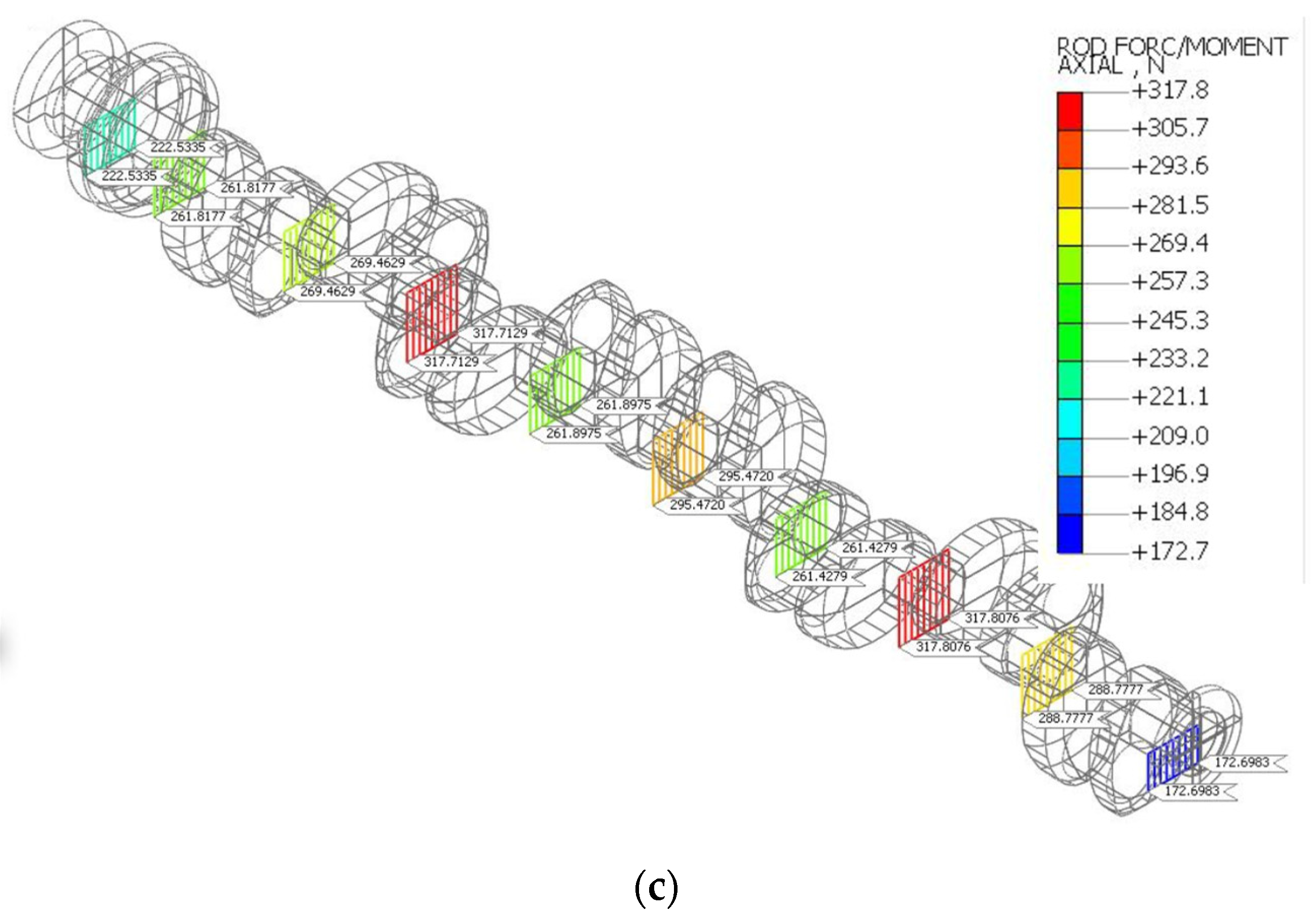
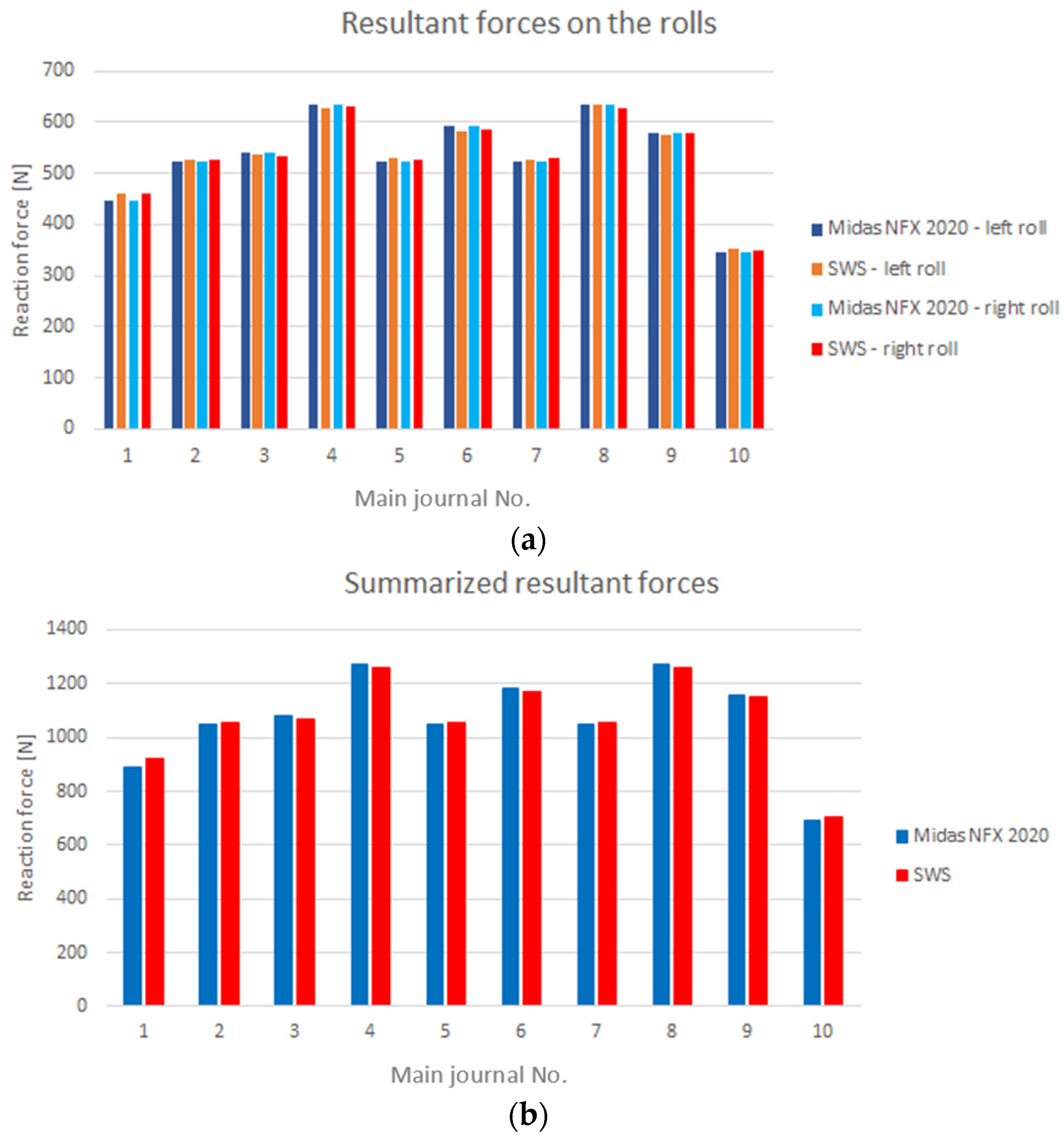
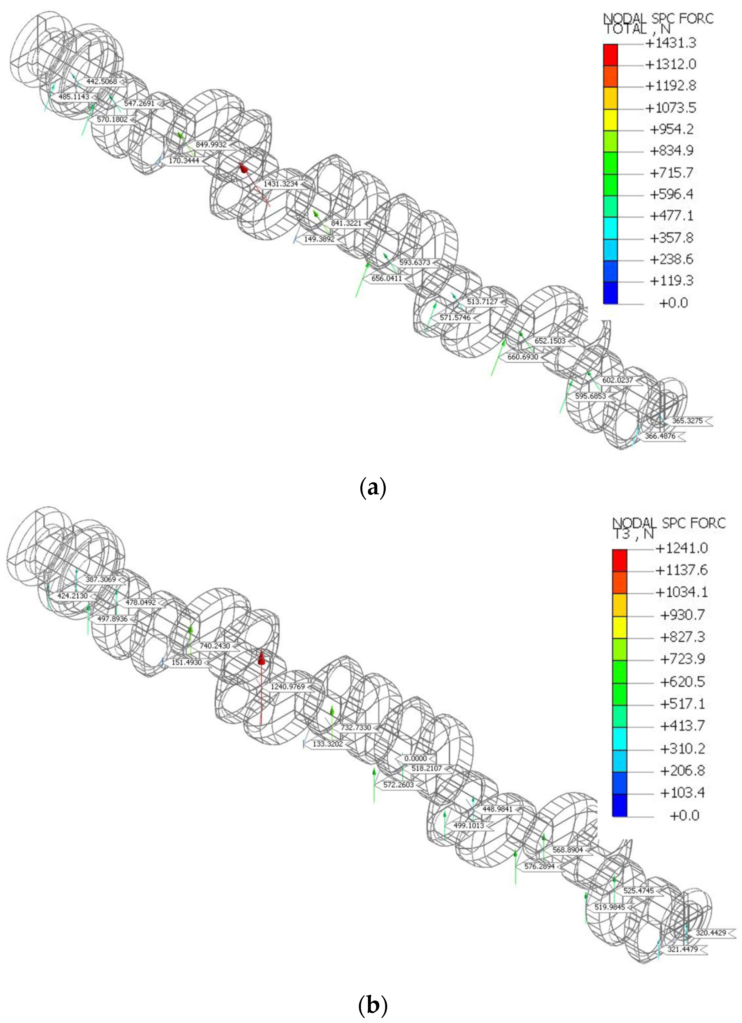
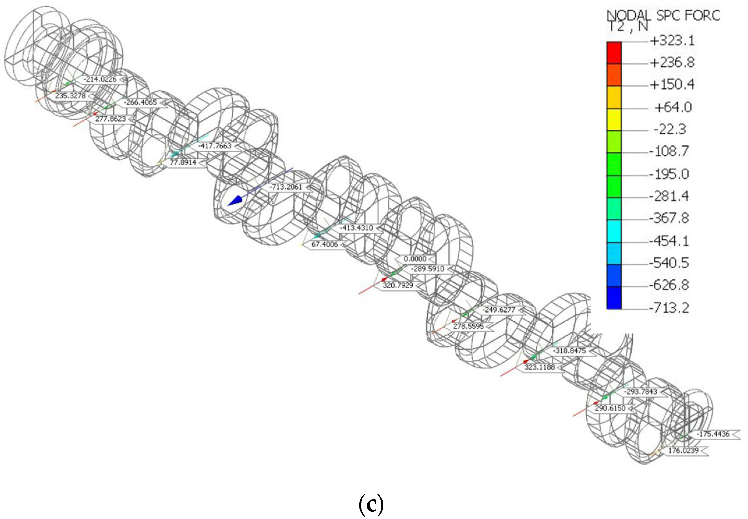
  • The determined values of the reaction forces ensuring the elimination of shaft deflections, assuming the nodal support, can be treated as corresponding to the resultant reaction forces realized by the prismatic heads.
  • The use of the developed system in practical measurements may improve the measurement techniques used so far, increasing the efficiency and credibility of the assessment of the geometrical condition of the crankshafts.

Author Contributions

Conceptualization, K.N. and Z.G.; methodology, K.N. and Z.G.; software, Z.G. and M.S.; validation, K.N. and Z.G.; formal analysis, K.N. and Z.G.; investigation, Z.G. and M.S.; resources, Z.G. and M.S.; data curation, Z.G. and M.S.; writing—original draft preparation, K.N., Z.G. and R.G.; writing—review and editing, M.W. and R.G.; visualization, Z.G. and M.S.; supervision, K.N.; project administration, K.N.; funding acquisition, M.W. and R.G. All authors have read and agreed to the published version of the manuscript.

Funding

This research received no external funding.

Institutional Review Board Statement

Not applicable.

Informed Consent Statement

Not applicable.

Data Availability Statement

Data are available upon request from the corresponding author.

Conflicts of Interest

The authors declare no conflict of interest.

References

  1. Murawski, L. Kinematic of marine piston-crankshaft system. J. KONES Powertrain Transp. 2015, 22, 155–162. [Google Scholar] [CrossRef] [Green Version]
  2. Gomes, J.; Gaivota, N.; Martins, R.F.; Pires Silva, P. Failure analysis of crankshafts used in maritime V12 diesel engines. Eng. Fail. Anal. 2018, 92, 466–479. [Google Scholar] [CrossRef]
  3. Sun, J.; Wang, J.; Gui, C. Whole crankshaft beam-element finite-element method for calculating crankshaft deformation and bearing load of an engine. Proc. Inst. Mech. Eng. Part J J. Eng. Tribol. 2010, 224, 299–303. [Google Scholar] [CrossRef]
  4. Walczyk, W.; Milenin, A.; Pietrzyk, M. Computer aided design of new forging technology for crank shafts. Steel Res. Int. 2011, 82, 187–194. [Google Scholar] [CrossRef]
  5. Nozdrzykowski, K.; Grządziel, Z.; Dunaj, P. Analysis of contact deformations in support systems using roller prisms. Materials 2021, 14, 2644. [Google Scholar] [CrossRef] [PubMed]
  6. Koehler, H.; Partes, K.; Seefeld, T.; Vollertsen, F. Laser reconditioning of crankshafts: From lab to application. Phys. Procedia 2010, 5, 387–397. [Google Scholar] [CrossRef] [Green Version]
  7. Ramana, A.V.; Raghav, G.R. Dynamic load analyzing and optimization of crankshaft. J. Crit. Rev. 2020, 7, 2332–2338. [Google Scholar]
  8. Grubišić, V.; Vulić, N.; Sönnichsen, S. Structural durability validation of bearing girders in marine Diesel engines. Eng. Fail. Anal. 2008, 15, 247–260. [Google Scholar] [CrossRef]
  9. Murawski, L. Shaft line alignment analysis taking ship construction flexibility and deformations into consideration. Mar. Struct. 2005, 18, 62–84. [Google Scholar] [CrossRef]
  10. Nozdrzykowski, K. Prevention of elastic strains in flexible large size machine parts with the use of elastic support. Mach. Dyn. Res. 2015, 39, 111–122. [Google Scholar]
  11. Gu, T.; Qian, X.; Lou, P. Research on high precision rapid online measurement system of crankshaft based on multi-station. J. Phys. Conf. Ser. 2021, 2101, 012016. [Google Scholar] [CrossRef]
  12. Liu, Y.; Zhou, H.; Zhao, D.; Guan, X.; Li, G.; Feng, F. Online approach to measuring relative location of spatial geometric features of long rotating parts. Measurement 2022, 187, 110317. [Google Scholar] [CrossRef]
  13. Bin, G.; Li, X.; Shen, Y.; Wang, W. Development of whole-machine high speed balance approach for turbomachinery shaft system with N+1 supports. Measurement 2018, 122, 368–379. [Google Scholar] [CrossRef]
  14. Nozdrzykowski, K.; Grządziel, Z.; Dunaj, P. Determining geometrical deviations of crankshafts with limited detection possibilities due to support conditions. Measurement 2022, 189, 110430. [Google Scholar] [CrossRef]
  15. Jadhav, A.; Chalwa, V.; Gaikwad, P. Fatigue failure analysis of marine engine crankshaft. Int. J. Eng. Res. Technol. 2013, 2, 614–621. [Google Scholar]
  16. Fonte, M.; Duarte, P.; Anes, V.; Freitas, M.; Reis, L. On the assessment of fatigue life of marine diesel engine crankshafts. Eng. Fail. Anal. 2015, 56, 51–57. [Google Scholar] [CrossRef]
  17. Dukalski, P.; Będkowski, B.; Parczewski, K.; Wnęk, H.; Urbaś, A.; Augustynek, K. Analysis of the influence of motors installed in passenger car wheels on the torsion beam of the rear axle suspension. Energies 2022, 15, 222. [Google Scholar] [CrossRef]
  18. Grzejda, R.; Warzecha, M.; Urbanowicz, K. Determination of the preload of bolts for structural health monitoring of a multi-bolted joint: FEM approach. Lubricants 2022, 10, 75. [Google Scholar] [CrossRef]
  19. Jiménez Espadafor, F.; Becerra Villanueva, J.; Torres García, M. Analysis of a diesel generator crankshaft failure. Eng. Fail. Anal. 2009, 16, 2333–2341. [Google Scholar] [CrossRef]
  20. Becerra, J.A.; Jimenez, F.J.; Torres, M.; Sanchez, D.T.; Carvajal, E. Failure analysis of reciprocating compressor crankshafts. Eng. Fail. Anal. 2011, 18, 735–746. [Google Scholar] [CrossRef]
  21. Sun, M.Y.; Lu, S.P.; Li, D.Z.; Li, Y.Y.; Lang, X.G.; Wang, S.Q. Three-dimensional finite element method simulation and optimization of shrink fitting process for a large marine crankshaft. Mater. Des. 2010, 31, 4155–4164. [Google Scholar] [CrossRef]
  22. Çevik, G.; Gürbüz, R. Evaluation of fatigue performance of a fillet rolled diesel engine crankshaft. Eng. Fail. Anal. 2013, 27, 250–261. [Google Scholar] [CrossRef]
  23. Metkar, R.M.; Sunnapwar, V.K.; Hiwase, S.D.; Anki, V.S.; Dumpa, M. Evaluation of FEM based fracture mechanics technique to estimate life of an automotive forged steel crankshaft of a single cylinder diesel engine. Procedia Eng. 2013, 51, 567–572. [Google Scholar] [CrossRef] [Green Version]
  24. Kakade, P.; Pasarkar, M.D. Analyzing and identifying various approaches for crankshaft failures. J. Multidiscip. Eng. Sci. Technol. 2015, 2, 76–92. [Google Scholar]
  25. Król, R.; Siemiątkowski, Z. The analysis of shrink-fit connection—The methods of heating and the factors influencing the distribution of residual stresses. Heliyon 2019, 5, e02839. [Google Scholar] [CrossRef]
  26. Chybowski, L.; Nozdrzykowski, K.; Grządziel, Z.; Jakubowski, A.; Przetakiewicz, W. Method to increase the accuracy of large crankshaft geometry measurements using counterweights to minimize elastic deformations. Appl. Sci. 2020, 10, 4722. [Google Scholar] [CrossRef]
  27. Xing, H.; Wu, Q.; Wu, Z.; Duan, S. Elastohydrodynamic lubrication analysis of marine sterntube bearing based on multi-body dynamics. Energy Procedia 2012, 16, 1046–1051. [Google Scholar] [CrossRef] [Green Version]
  28. Nozdrzykowski, K. Methodology of Geometric Measurements of Deviations of Cylindrical Surfaces of Large-Size Machine Elements Based on the Example of Ship Engine Crankshafts; Scientific Publishing House of the Maritime University of Szczecin: Szczecin, Poland, 2013. (In Polish) [Google Scholar]
  29. Nozdrzykowski, K.; Janecki, D. Comparative studies of reference measurements of cylindrical surface roundness profiles of large machine components. Metrol. Meas. Syst. 2014, 21, 67–76. [Google Scholar] [CrossRef] [Green Version]
  30. Nozdrzykowski, K.; Chybowski, L. A force-sensor-based method to eliminate deformation of large crankshafts during measurements of their geometric condition. Sensors 2019, 19, 3507. [Google Scholar] [CrossRef] [Green Version]
  31. Chybowski, L.; Nozdrzykowski, K.; Grządziel, Z.; Dorobczyński, L. Evaluation of model-based control of reaction forces at the supports of large-size crankshafts. Sensors 2020, 20, 2654. [Google Scholar] [CrossRef]
Figure 1. FEM model with the applied boundary conditions for the crankshaft support by the concentrated forces on the nodes located at the half-length of main journals.
Lubricants 10 00151 g001
Figure 2. The values of the reaction forces for removing deformations on the individual main journals for the initial angular position of the shaft (angle of rotation 0°).
Lubricants 10 00151 g002
Figure 3. The values of the reaction forces when changing the crankshaft position within the range of full rotation angle 0 ÷ 360° presented in: (a) the Cartesian coordinate system, (b) the polar coordinate system.
Lubricants 10 00151 g003aLubricants 10 00151 g003b
Figure 4. The calculated values of the reaction forces, based on the FEM programs Midas NFX 2020 and PrePoMax, ensuring the elimination of deformations on the individual main journals for the initial position of the crankshaft (angle of rotation 0°).
Lubricants 10 00151 g004
Figure 5. The FEM model with the assumed boundary conditions for the roller prism shaft support.
Lubricants 10 00151 g005
Figure 6. The values of the reaction forces for “rigid” rollers: (a) resultant reactions, (b) vertical reactions, (c) horizontal reactions.
Lubricants 10 00151 g006
Figure 7. The values of the reaction forces for “compliant” rollers: (a) resultant reactions, (b) vertical reactions, (c) horizontal reactions.
Lubricants 10 00151 g007aLubricants 10 00151 g007b
Figure 8. Resultant reaction forces on adjacent prism head rolls (a) and total resultant reaction forces (b) calculated using Midas NFX 2020 and Solid Works Simulation FEA programs.
Lubricants 10 00151 g008
Figure 9. The values of the reaction forces for “rigid” rollers and for the crankshaft with the main journals coaxial misalignment: (a) resultant reactions, (b) vertical reactions, (c) horizontal reactions.
Lubricants 10 00151 g009aLubricants 10 00151 g009b
Table 1. Basic technical data of Buckau-Wolf engine crankshaft R8VD-136.
ParameterValue
Crankshaft length3630 mm
Crankshaft weight9360 N
Number of crank journals8
Number of main journals10
Main journal diameter149 mm
Crank journal diameter144 mm
Crank dimensions252 mm × 358 mm (oval)
Material Poison ratio (steel)0.3
Material Young modulus (steel)210 GPa
Publisher’s Note: MDPI stays neutral with regard to jurisdictional claims in published maps and institutional affiliations.

