Article

Friction-Excited Oscillation of Air Conditioner Rotary Compressors: Measurements and Numerical Simulations

1
State Key Laboratory of Air-Conditioning Equipment and System Energy Conservation, Zhuhai 519070, China
2
GREE Electric Appliances Inc. of Zhuhai, Zhuhai 519070, China
3
School of Mechanical Engineering, Southwest Jiaotong University, Chengdu 610031, China
*
Author to whom correspondence should be addressed.
Lubricants 2022, 10(4), 50; https://doi.org/10.3390/lubricants10040050
Submission received: 16 February 2022 / Revised: 21 March 2022 / Accepted: 22 March 2022 / Published: 25 March 2022
(This article belongs to the Special Issue Tribology in Manufacturing and Design)

Abstract

:
The oscillation of a rotary compressor was measured and analyzed in the frequency and time domains. The harmonic wavelet transform was used to dissolve the oscillation signal into a series of single-frequency components. A power spectrum analysis of the single-frequency components shows that there are many vibration components whose frequencies are one, double, triple, quadruple, and even tens of times the rotating frequency. An envelope spectrum analysis shows that some single-frequency components originate from the friction-excited oscillation of the compressor. A full-size mode-coupling model of the rotary compressor was established to forecast the friction-excited oscillation of the compressor using the transient dynamics method and the complex eigenvalue method. The measurement results are consistent with the predictive results. A sensitivity analysis of the main parameters shows that the coefficient of friction has a major impact on the development tendency of the friction-excited oscillation of rotary compressors.

1. Introduction

With the improvement of people’s living standards, higher and higher requirements for the quality of air conditioners have become necessary. Because houses are quieter than public places, customers are demanding quieter household air conditioners. It has been identified that the air conditioner noise mainly consists of mechanical noise [1,2,3], electromagnetic noise, and aerodynamic noise [4,5,6,7,8]. In the air conditioner noise level, the noise of the outside unit of the air conditioner accounts for a large part. The compressor in the outside unit is the main noise source. The compressor has a significant level of influence on the noise level of the outside unit. Although the shell of the compressor is wrapped with sound-absorbing cotton and other materials for sound absorption and insulation, a lot of noise still radiates to the outside of the compressor. Moreover, the oscillation of the compressor will stimulate the resonance of the other parts of air conditioners, such as the pipeline, motor support, and compressor shell, and then radiate new noise. Friction-excited noise is a significant part of the mechanical noise of air conditioner compressors. Therefore, the research on the friction-excited oscillation and noise of compressors is valuable for reducing the overall noise level of air conditioners.
Friction-induced vibration and noise, such as automobile disc brake squeal, have been studied a lot over the past one hundred years. Significantly, the generation mechanism for brake squeal has been studied extensively in the past twenty years [9,10,11,12,13,14]. Up to now, six generations of mechanisms for brake squeal have been proposed, which included stick-slip, negative friction–velocity slope, sprag-slip, mode coupling, splitting the doublet modes, hammering, and thermoelastic instability [15,16]. Among these six mechanisms, the mode-coupling mechanism was generally accepted. Nowadays, the common finite element analysis of squeal is based on the mode-coupling mechanism [17,18]. For automobile disc brake systems consisting of a cast iron disc and two composite pads, sometimes brake squeal occurs, but sometimes no brake squeal occurs. More recently, the uncertainty of this brake squeal has also been studied [19,20,21].
The goal of the paper is to survey the formation mechanism behind the friction-excited oscillation and noise of a rotary compressor on the basis of the measurement of the oscillation of rotary compressors, the identification of the measured friction-excited oscillation of compressors, and the numerical imitation of the friction-excited oscillation of compressors.

2. Measurement of Oscillation and Noise of Rotary Compressors

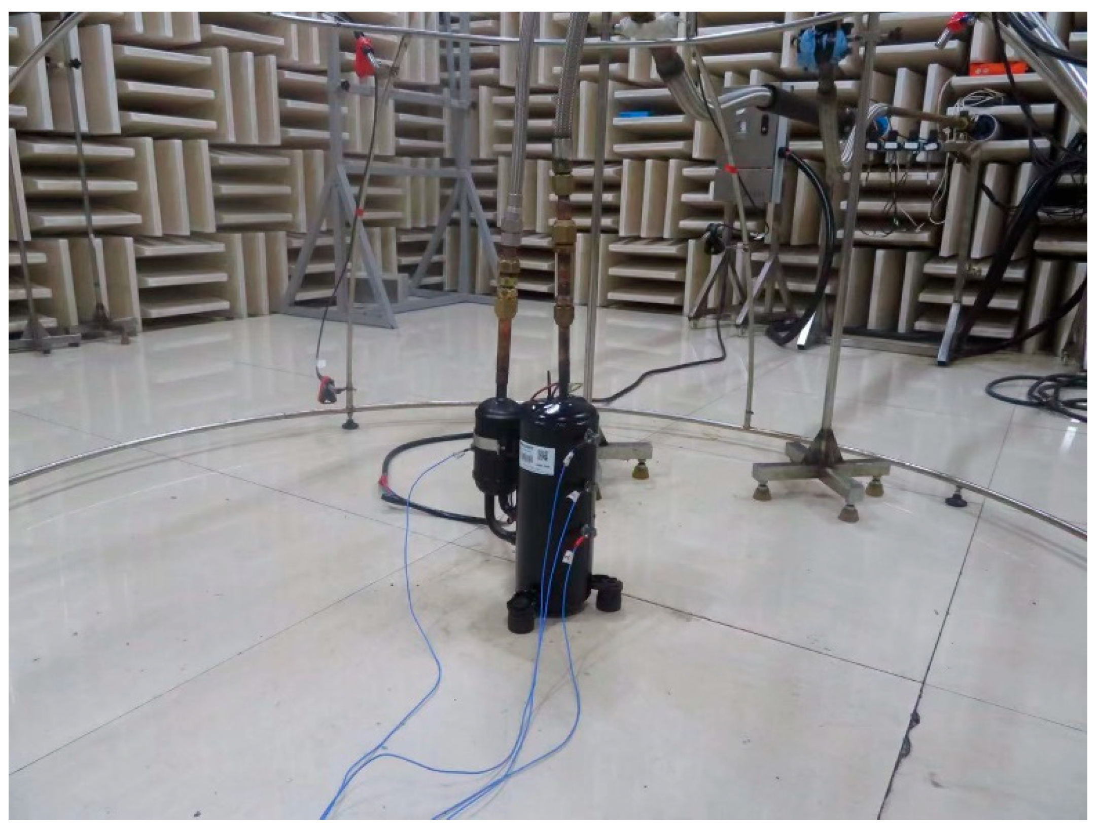
2.1. Test and Measurement Details

The oscillation and noise of rotary compressors were measured in an anechoic chamber, which is a very key experimental place for noise tests and acoustic experiments. The anechoic chamber provides a low-noise-level test environment in a semi-free field space or a free field space and is equipped with good sound and vibration isolation devices to avoid interference from the external environment. Figure 1 shows a picture of the measurement site of the oscillation and noise of rotary compressors experiment. The rotary compressor was located at the center of the anechoic chamber. Four 3D accelerometers were attached to the shell of the rotary compressor. Three microphones were fixed on the semi-ball-type frame. All vibration and sound signals were acquired simultaneously with a data acquisition system.

2.2. Test Parameters and Procedure

In the present test, the rotary compressor was a kind of variable frequency compressor. The rotating speed of the compressor depends on the frequency of the electric power that is input to the compressor. The rotating speed of the compressor is governed by the below equation:
n = 60f
where n stands for the rotating speed of the compressor crankshaft (rpm) and f stands for the rotating frequency of the electric power. In general, the working rotating speed of the compressor is located in the range of 1800–5400 rpm. Therefore, the rotating frequencies of the electric power were set as 30, 40, 50, 60, 70, 80, and 90 Hz, corresponding to the rotating speeds of 1800, 2400, 3000, 3600, 4200, 4800, and 5400 rpm, respectively.
For each rotating frequency, the compressor was run for ten minutes, and then the vibration and sound signals were collected at an acquiring frequency of 25,600 Hz. Each measurement time duration was about 11 s.

2.3. Extraction Approach of Friction-Excited Oscillation of Compressors

The rotary compressor is a typical piece of rotating machinery. When the lubrication of various compressor friction pairs is in good condition, no friction-excited vibration occurs. However, when the lubrication of various compressor friction pairs is in bad condition, and the eccentricity of the rotating components is too large, rubbing impact oscillation and friction-excited oscillation will be excited. The rubbing impact fault of the rotor system usually excites high-frequency vibrations whose frequencies are n times the rotating frequency (n = 1, 2, 3…) [22,23,24,25]. In addition, the friction-excited vibration due to the rubbing impact probably occurs, which is modulated by the rotating frequency of the rotors. In the paper, the harmonic wavelet transform was applied to dissolve the oscillation signals of compressors into a series of single-frequency components [26,27]. The modulation frequency of the single-frequency components was detected using the envelope spectrum analysis approach. If the modulation frequency was equal to n times the rotational frequency of the compressor (n = 1, 2, 3…), then this single-frequency component was considered to be a friction-excited oscillation.

3. Modeling of the Friction-Excited Oscillation of Compressors

3.1. Modeling of the Friction-Excited Oscillation Due to Mode Coupling

In the paper, a mode-coupling model of the friction-excited oscillation of the rotary compressor was established.
The motion equation of a compressor is written as follows [17,18]:
M r y ¨ + C r y ˙ + K r y = 0
where M r , C r , and K r are asymmetric matrices caused by friction, and y is the oscillation displacement vector of compressor nodes.
Figure 2 shows the structural drawing of a rotary compressor. It is mainly composed of a crankshaft, a motor, the main bearing, two rollers, a cylinder, a sub-bearing, a shell, etc. Figure 3 shows the solid model and the section view of the rotary compressor. Figure 4 demonstrates the simulation model of the rotary compressor. It is worthy of note to add that the motor rotor was omitted in the simulation model because it was connected with the crankshaft by a flat key without friction sliding. There are six main friction couples, which include one consisting of the crankshaft and main bearing, one consisting of the crankshaft and sub-bearing, one consisting of the upper roller and upper vane, one consisting of the lower roller and lower vane, one consisting of the upper roller and cylinder, and one consisting of the lower roller and cylinder. In the model, relative motions were imposed on these six friction couples.

3.2. Complex Eigenvalue Analysis of Friction-Excited Oscillation

The eigenvalue equation of Equation (1) is governed by the below equation:
M r λ 2 + C r λ + K r Ψ = 0
The general solution of Equation (1) is given as follows:
y t = Ψ i e x p ( λ i t ) = Ψ i e x p α i + j ω i t
where λ i = α i + j ω i is the ith eigenvalue of Equation (2), Ψ i is the ith eigenvector of Equation (2), and j is the imaginary unit. From Equation (3), one can see that when a real part of the eigenvalues is larger than zero, the displacement of the compressor nodes will diverge with time, that is, the oscillation of the compressor nodes becomes unstable. In the literature, the effective damping ratio is generally applied to measure whether unstable oscillations of the friction system occur, which is defined as below:
ξ = 2 α | ω |
When the effective damping ratio is less than zero, the system loses stability [17,18]. The smaller the effective damping ratio, the more easily the unstable oscillation occurs.

3.3. Transient Dynamic Analysis of Friction-Excited Oscillation

The complex eigenvalue analysis provides the general overview of all possible friction-excited oscillations, while the transient dynamic analysis reflects the strength of a certain friction-excited oscillation. In the transient dynamic analysis, Equation (1) was integrated using the explicit integration method [18]. In the explicit integration method, the overall equilibrium equation of the friction system was set up at the beginning of each time increment. Namely, it might be expressed as below:
M y ¨ t = P t I t
where [M] represents the nodal mass matrix, y ¨ represents the nodal acceleration vector, and P and I represent the external applied force vector and internal element force vector, respectively. The acceleration vector of all nodes at t time is obtained:
y ¨ t = [ M ] 1 P t I t
The velocity and displacement of all nodes can be obtained using the central difference method as follows:
y ˙ t + 0.5 Δ t = y ˙ t 0.5 Δ t + Δ t t + Δ t + Δ t t 2 y ¨ t
y t + Δ t = y t + Δ t t + Δ t y ˙ t + 0.5 Δ t
where the subscripts (t − 0.5Δt) and (t + 0.5Δt) represent the mid-increment values, and Δt is the time increment.

3.4. Material Property Parameters of the Compressor Model

The material property parameters of compressor parts are listed in Table 1.

3.5. Boundary Conditions

In practical compressors, the main bearing is attached to the shell, and the main bearing, sub-bearing, two cylinders, and partition are fixed into a whole structure by four screws. In the finite element model, therefore, the outer face of the main bearing was fixed. The main bearing, sub-bearing, two cylinders, and partition were connected into a whole structure by tie constraints.
The forces acting on the main components of rotary compressors are shown in Figure 5, including the gas force ( F r ), friction force ( F rv ), and normal force ( N rv ) between the vane and roller and the friction force ( F rc ) and normal force ( N rc ) between the roller and cylinder. F is the resultant force of all external forces. Its two components ( F x , F y ) changed from 1240 N to 0 and −1840 N to 0 [28,29].

3.6. Friction Coefficients

In practical applications, various friction pairs of the rotary compressor were well lubricated. A pin–disk test rig was applied to gauge the coefficients of friction of various friction couples of the rotary compressor. The friction couples were lubricated with the same lubricant as in the compressor. Figure 6 displays the change in the measured coefficients of friction with the slip speed. It is found that the coefficients of friction decreased with the increasing of the slip speed.

4. Results and Discussion

4.1. Identification of the Rub Impact Fault and Friction-Excited Vibration of Rotary Compressors

Figure 7 shows a measured vibration acceleration of the compressor shell and its power spectrum density analysis. From Figure 7b, it is found that there are vibration components whose frequencies are 1–22 times the rotating frequency, suggesting that the rub impact between the rotational compressor part and the static compressor part occurs in this case [23,24]. Given the compressor structure, the rub impact probably occurred on the friction pair between the crankshaft and main/sub-bearing, or between the roller and cylinder.
One can find that the frequency elements of the compressor oscillation are very complex from Figure 7b. In this paper, the harmonic wavelet transform and the envelope spectrum analysis were jointly used to extract the friction-excited oscillation component of the overall oscillation signal of compressors. An 11-layer harmonic wavelet transform was used to dissolve the measured overall oscillation signal of the compressor into the oscillation components with 2048 frequency bands whose bandwidth was 6.25 Hz. After the harmonic wavelet transform, a series of single-frequency components was obtained. Since it is excited by the contact between two friction parts, the friction-excited oscillation is generally modulated by the compressor’s rotating frequency. The envelope spectrum is a useful tool for detecting this modulation frequency. In the paper, if the characteristic frequency of the envelope spectrum of an oscillation component from the harmonic wavelet transform is equal to the rotating frequency of the compressor, this component was thought to be a friction-excited oscillation component. The sum of all friction-excited oscillation components was thought to be the friction-excited vibration signal of the compressor. Figure 8 shows the extracted friction-excited oscillation of the compressor and its amplitude spectrum analysis. One can see that the first major frequency of the extracted friction-excited oscillation is about 7640 Hz.

4.2. Prediction of the Friction-Excited Oscillation of the Rotary Compressor

Using the model demonstrated in Figure 4, the friction-excited oscillation of the rotary compressor can be predicted. Firstly, a static nonlinear contact analysis was performed under the application of various external forces. Secondly, a nonlinear contact analysis was conducted after imposing the rotating speed of the crankshaft. Thirdly, a mode analysis was conducted to obtain the resonance frequencies of the compressor. Fourthly, a complex eigenvalue analysis was conducted to extract the unstable propensity of the compressor system, which incorporates the friction coupling. Figure 9 shows the distribution of contact forces at the main friction couples of the compressor. One can see that six main friction couples all probably induce frictional oscillation from Figure 9, which include those between the crankshaft and main bearing, between the crankshaft and sub-bearing, between the vanes and rollers, and between the rollers and cylinders. Figure 10 shows the formation tendency of the friction-motivated oscillation of the compressor and their corresponding oscillation modes. It is seen that there are two friction-excited vibrations whose frequencies are 7169.4 Hz and 10,259.7 Hz, respectively. By comparing Figure 8b and Figure 10a, one can see that the frequency of the measured friction-motivated oscillation is roughly equal to that of the predicted friction-motivated oscillation.

4.3. Effect of Friction Coefficient on Friction-Motivated Oscillation of the Rotary Compressor

It is well known that the formation tendency of the friction-motivated oscillation and squeal increases with increasing friction coefficient in the academic community. The friction-motivated oscillation and noise of water-lubricated bearings have been studied, in which the friction coefficient between the shaft and bushing is about 0.08–0.18 [30,31]. In general, various friction couples of the rotary compressor are well lubricated. In this case, the coefficients of friction of various friction couples of the rotary compressor are very small at about 0.08–0.15, as shown in Figure 6. When the lubricant is degraded, however, the friction coefficients would probably increase. Figure 11 displays the change in the effective damping ratio with respect to the coefficient of friction. One can see that when the coefficient of friction is less than 0.07, no friction-motivated oscillation occurs. One can find, as well, that the larger the coefficient of friction, the smaller the negative effective damping ratio, suggesting that friction-motivated oscillation more easily occurs with an increasing friction coefficient.

4.4. Effect of Elastic Modulus on Friction-Motivated Oscillation of the Rotary Compressor

The elastic modulus of materials has an effect on the contact stiffness between two contact surfaces and, thus, on the friction-motivated oscillation of tribological systems. Figure 12 displays the variation of the effective damping ratio against the elastic modulus of the main bearing. From Figure 12, it is observed that the elastic modulus of the main bearing has an effect on the friction-motivated oscillation of the compressor in the range of 0.6–1.4 E0, where E0 is the elastic modulus of the main bearing, being equal to 130 GPa, as shown in Table 1. The formation tendency of the friction-motivated oscillation of the compressor decreases with the decrease in the elastic modulus of the main bearing.

4.5. Transient Dynamic Analysis of Friction-Motivated Oscillation of the Rotary Compressor

Nowadays, there are two analysis methods available for the prediction of friction-excited oscillation. One is called the complex eigenvalue analysis, which can establish an overall outlook of unstable modes of the compressor. The other is called the transient dynamic analysis, which can reflect the evolution of a certain friction-excited vibration. Figure 13 demonstrates the transient dynamics of measurement point two of the compressor and its power spectrum density analysis.

4.6. Effect of Damping Ring on Friction-Motivated Vibration of the Rotary Compressor

The motion stability analysis results show that when the unstable oscillation of the rotary compressor occurs, the displacement of the contact area between the main bearing and crankshaft is larger. In the rotary compressor, the sub- and main bearings were fixed to the shell by welding, and other main parts were fixed to the main and sub-bearings using screws. In order to reduce the friction-excited oscillation of the compressor, a damping ring was applied. The damping ring has the characteristics of both simple structure and good applicability. In the actual application, the damping ring only needs to be embedded and fixed firmly in the system requiring vibration and noise reduction. When the system vibrates due to external excitations, the damping effect will be generated between the damping ring and the part in contact due to dry friction, and the energy of system vibration will be converted into heat energy and dissipated to help achieve the effect of vibration and noise reduction. In the present work, a damping ring was fixed on the main bearing as shown in Figure 14. The author introduced the damping characteristics of the damping ring into the finite element model of the rotary compressor using Rayleigh damping. It was surmised that the damping matrix of the compressor system was a linear sum of the stiffness matrix and the mass matrix, namely [C] = α[M] + β[K]. The values of coefficients α and β were equal to 0.5 and 5 × 10⁻⁵, respectively. In the model, the damping ring was connected to the main bearing with the tie constraint.
Figure 15 shows a distribution of unstable modes of the rotary compressor. By comparing Figure 10a and Figure 15, it is seen that when the damping ring was applied, the friction-excited oscillation of the compressor could be suppressed to some extent.

5. Conclusions

In this paper, the oscillation of the rotary compressor was measured and analyzed. The component of the friction-motivated oscillation of the compressor was extracted. The model prediction of the friction-motivated oscillation of the compressor was conducted. The following several conclusions can be drawn:
  • There are many vibration components in the measured vibration of the compressor shell, frequencies of which are one, double, triple, quadruple, and even tens of times the rotating frequency of the rotary compressor, suggesting that rub impact occurs between the rotating components and static components of the rotary compressor.
  • The friction-motivated vibration of the rotary compressor can be identified using the harmonic wavelet transform and the envelope spectrum analysis.
  • The complex eigenvalue analysis of the mode-coupling model of the rotary compressor can be used to forecast the friction-motivated oscillation of the compressor.
  • The coefficient of friction has an important effect on the friction-motivated oscillation of the compressor. When the coefficient of friction is less than 0.07, no friction-motivated oscillation of the compressor occurs.

Author Contributions

Conceptualization, Y.H. and R.Z.; methodology, G.C.; software, Q.S.; validation, G.C. and Q.S.; formal analysis, G.C. and Q.S.; investigation, G.C. and Q.S.; resources, G.C.; data curation, J.Z.; writing—original draft preparation, G.C.; writing—review and editing, G.C., and Q.S.; visualization, G.C. and Q.S.; supervision, G.C.; project administration, Y.H. and R.Z.; funding acquisition, G.C. All authors have read and agreed to the published version of the manuscript.

Funding

The authors are grateful for financial support from the State Key Laboratory of Air-conditioning Equipment and System Energy Conservation (ACSKL2019KT01).

Institutional Review Board Statement

Not applicable.

Informed Consent Statement

Not applicable.

Data Availability Statement

Not applicable.

Conflicts of Interest

The authors declare that they have no known competing financial interest or personal relationship that could have appeared to influence the work reported in this paper.

References

  1. Hay, B.; Kemp, M.F. Frequency analysis of air conditioning noise in landscaped offices. J. Sound Vib. 1972, 23, 375–381. [Google Scholar] [CrossRef]
  2. Jie, T.; Ouyang, H.; Wu, Y. Experimental and numerical study on aerodynamic noise of outdoor unit of room air conditioner with different grilles. Int. J. Refrig. 2009, 32, 1112. [Google Scholar]
  3. Han, H.S.; Jeong, W.B.; Aoyama, S.; Mo, J.Y. Experimental analysis for reducing refrigerant-induced noise of 4-way cassette type air conditioner. J. Mech. Sci. Technol. 2009, 23, 1456–1467. [Google Scholar] [CrossRef]
  4. Soeta, Y.; Shimokura, R. Sound quality evaluation of air-conditioner noise based on factors of the autocorrelation function. Appl. Acoust. 2017, 124, 11–19. [Google Scholar] [CrossRef]
  5. Sugio, T.; Sano, K.; Izumi, Y.; Sakai, H. Noise sources of room air conditioners and their reduction techniques. Turbomachinery 1998, 26, 80–86. [Google Scholar]
  6. Jang, S.; Choung, H.; Park, S.; Lee, S. Investigation on noise of rotary compressors using fluid-structure interaction. J. Mech. Sci. Technol. 2019, 33, 5129–5135. [Google Scholar] [CrossRef] [Green Version]
  7. Lee, J.; Lee, U.Y. Design optimization of an accumulator for reducing rotary compressor noise. Proc. Inst. Mech. Eng. Part E J. Process Mech. Eng. 2012, 226, 285–296. [Google Scholar] [CrossRef]
  8. Kim, H.C.; Cho, M.G.; Kim, J.; Park, J.H.; Shim, J. Coherence technique for noise reduction in rotary compressor. J. Mech. Sci. Technol. 2012, 26, 2073–2076. [Google Scholar] [CrossRef]
  9. Lijun, Z.; Yongchao, D.; Dejian, M.; Wenbo, L. A hybrid model for predicting steering brake squeal based on multibody dynamics and finite element methods. Shock. Vib. 2022, 2022, 1906498. [Google Scholar]
  10. Dejian, M.; Jun, W.; Lijun, Z. Transient Analysis of a Flexible Pin-on-Disk System and Its Application to the Research into Time-Varying Squeal. J. Vib. Acoust. 2017, 140, 011006. [Google Scholar]
  11. Lazzari, A.; Tonazzi, D.; Massi, F. Squeal propensity characterization of brake lining materials through friction noise measurements. Mech. Syst. Signal Process. 2019, 128, 216–228. [Google Scholar] [CrossRef]
  12. Brunetti, J.; Massi, F.; D’Ambrogio, W.; Berthier, Y. A new instability index for unstable mode selection in squeal prediction by complex eigenvalue analysis. J. Sound Vib. 2016, 377, 106–122. [Google Scholar] [CrossRef]
  13. Baillet, L.; D’Errico, S.; Laulagnet, B. Understanding the occurrence of squealing noise using the temporal finite element method. J. Sound Vib. 2005, 292, 443–460. [Google Scholar] [CrossRef]
  14. Tang, B.; Mo, J.L.; Zhang, X.; Zhang, Q.; Zhu, M.H.; Zhou, Z.R. Experimental investigation of the squeal characteristics in railway disc brakes. Proc. Inst. Mech. Eng. Part J J. Eng. Tribol. 2018, 232, 1437–1449. [Google Scholar] [CrossRef]
  15. Kinkaid, N.M.; O’Reilly, O.M.; Papadopoulos, P. Automotive disc brake squeal. J. Sound Vib. 2003, 267, 105–166. [Google Scholar] [CrossRef]
  16. Ibrahim, R.A. Friction-induced vibration, chatter, squeal, and chaos. Part 2. Dynamics and modeling. Appl. Mech. Rev. 1994, 47, 227–253. [Google Scholar] [CrossRef]
  17. Nack, W.V. Brake squeal analysis by finite elements. Int. J. Veh. Des. 2000, 23, 263–275. [Google Scholar] [CrossRef]
  18. Ouyang, H.; Nack, W.; Yuan, Y.; Chen, F. Numerical analysis of automotive disc brake squeal: A review. Int. J. Veh. Noise Vib. 2005, 1, 207–231. [Google Scholar] [CrossRef]
  19. Lu, H.; Shangguan, W.; Yu, D. Squeal reduction of a disc brake system with fuzzy uncertainties. J. Vibroeng. 2016, 18, 3981–4001. [Google Scholar] [CrossRef]
  20. Lu, H.; Shangguan, W.-B.; Yu, D. A unified approach for squeal instability analysis of disc brakes with two types of random-fuzzy uncertainties. Mech. Syst. Signal Process. 2017, 93, 281–298. [Google Scholar] [CrossRef]
  21. Amir, N.; Huajiang, O.; Paul, B. Uncertainty quantification of squeal instability via surrogate modelling. Mech. Syst. Signal Process. 2015, 60–61, 887–908. [Google Scholar]
  22. Li, Y.; Wang, S.; Yang, Y.; Deng, Z. Multiscale symbolic fuzzy entropy: An entropy denoising method for weak feature extraction of rotating machinery. Mech. Syst. Signal Process. 2022, 162, 108052. [Google Scholar] [CrossRef]
  23. Ahmad, S. Rotor casing contact phenomenon in rotor dynamics-literature survey. J. Vib. Control 2010, 16, 1369–1377. [Google Scholar] [CrossRef]
  24. Goldman, P.; Muszynska, A. Rotor-to-stator, rub-related, thermal/mechanical effects in rotating machinery. Chaos Solitons Fractals 1995, 5, 1579–1601. [Google Scholar] [CrossRef] [Green Version]
  25. Xing, P.; Li, G.; Gao, H.; Wang, G. Experimental investigation on identifying friction state in lubricated tribosystem based on friction-induced vibration signals. Mech. Syst. Signal Process. 2020, 138, 106590. [Google Scholar] [CrossRef]
  26. Newland, D.E. Wavelet analysis of vibration, Part 1: Theory. J. Vib. Acoust. 1994, 116, 409–416. [Google Scholar] [CrossRef]
  27. Newland, D.E. Harmonic wavelet analysis. Proc. R. Soc. Lond. 1993, 443, 203–205. [Google Scholar]
  28. Zhang, H.F.; Wu, J.H.; Xie, F.; Chen, A.; Li, Y.Z. Dynamic behaviors of the crankshafts in single-cylinder and twin-cylinder rotary compressors. Int. J. Refrig.-Rev. Int. Froid 2014, 47, 36–45. [Google Scholar] [CrossRef]
  29. Wang, Z.L.; Yu, X.L.; Liu, F.L.; Feng, Q.K.; Tan, Q. Dynamic analyses for the rotor-journal bearing system of a variable speed rotary compressor. Int. J. Refrig.-Rev. Int. Froid 2013, 36, 1938–1950. [Google Scholar] [CrossRef]
  30. Xiao, B.; Zheng, X.; Zhou, Y.; Yao, D.; Wan, Y. Tribological behaviors of the water-lubricated rubber bearings under different lubricated conditions. Ind. Lubr. Tribol. 2020, 73, 260–265. [Google Scholar] [CrossRef]
  31. Kuang, F.; Zhou, X.; Liu, Z.; Huang, J.; Liu, X.; Qian, K. Konstantinos Gryllias, Computer-vision-based research on friction vibration and coupling of frictional and torsional vibrations in water-lubricated bearing-shaft system. Tribol. Int. 2020, 150, 106336. [Google Scholar] [CrossRef]
Figure 1. Picture of the measurement site of the vibration and noise of rotary compressors experiment.
Lubricants 10 00050 g001
Figure 2. Structure draft of a rotary compressor.
Lubricants 10 00050 g002
Figure 3. Solid model of a rotary compressor and its section view: (a) solid model and (b) section view.
Lubricants 10 00050 g003
Figure 4. Finite element model of the rotary compressor.
Lubricants 10 00050 g004
Figure 5. Forces acting on the roller, vane, and cylinder.
Lubricants 10 00050 g005
Figure 6. The change of the coefficient of friction relative to the sliding speed: (a) at the friction pair consisting of the roller and cylinder, (b) at the friction pair consisting of the vane and roller, and (c) at the friction pair consisting of the crankshaft and main (sub) bearing.
Lubricants 10 00050 g006
Figure 7. Measured vibration acceleration of the compressor shell at a rotating frequency of 50 Hz and its amplitude spectrum analysis: (a) measured vibration acceleration and (b) amplitude spectrum analysis.
Lubricants 10 00050 g007
Figure 8. Measurement oscillation acceleration of the compressor shell at a rotating frequency of 50 Hz and its amplitude spectrum analysis: (a) measured oscillation acceleration and (b) amplitude spectrum analysis.
Lubricants 10 00050 g008
Figure 9. Distribution of the contact forces at main friction pairs: (a) between the crankshaft and main bearing, (b) between the crankshaft and sub-bearing, (c) between the vanes and rollers, and (d) between the rollers and cylinders.
Lubricants 10 00050 g009
Figure 10. Formation tendency of the friction-motivated oscillation of the compressor and their corresponding vibration modes: (a) distribution of the friction-motivated oscillation of the compressor, (b) vibration mode at a frequency of 7169.4 Hz, and (c) vibration mode at a frequency of 10,259.7 Hz.
Lubricants 10 00050 g010
Figure 11. The variation of the effective damping ratio with respect to the coefficient of friction.
Lubricants 10 00050 g011
Figure 12. The change in the effective damping ratio relative to the elastic modulus of the main bearing.
Lubricants 10 00050 g012
Figure 13. Transient dynamic analysis of friction-motivated oscillation of measurement point 2: (a) transient dynamics in x-direction and (b) PSD analysis of the transient dynamics in x-direction.
Lubricants 10 00050 g013
Figure 14. The assembly of the damping ring.
Lubricants 10 00050 g014
Figure 15. The distribution of the unstable modes of the rotary compressor.
Lubricants 10 00050 g015
Table 1. Material Property Parameters of Compressor Parts.
PartMaterialDensity (kg/m3)Modulus of Elasticity (MPa)Poisson’s Ratio
Main bearingHT2507300130,0000.3
CrankshaftDuctile iron7190163,0000.3
RollerFC3007200130,0000.3
CylinderGrey cast iron7070130,0000.26
Sub-bearingHT2507300130,0000.3
VaneStainless steel7600190,0000.3
Publisher’s Note: MDPI stays neutral with regard to jurisdictional claims in published maps and institutional affiliations.

