Article

Flooding Application of Vegetable- and Mineral-Based Cutting Fluids in Turning of AISI 1050 Steel

by
Déborah Oliveira Almeida Carvalho
1,
Leonardo Rosa Ribeiro da Silva
1,*,
Felipe Chagas Rodrigues de Souza
1,
Pedro Henrique Pires França
1,
Álisson Rocha Machado
1,2,
Eder Silva Costa
1,
Gustavo Henrique Nazareno Fernandes
1 and
Rosemar Batista da Silva
1
1
Faculty of Mechanical Engineering, Federal University of Uberlandia, Av. João Naves de Ávila, 2121, Uberlândia 38400-902, Brazil
2
Mechanical Engineering Graduate Program, Pontifícia Universidade Católica do Paraná–PUCPR, Rua Imaculada Conceição, 1155, Prado Velho, Curitiba 80215-901, Brazil
*
Author to whom correspondence should be addressed.
Lubricants 2022, 10(11), 309; https://doi.org/10.3390/lubricants10110309
Submission received: 7 October 2022 / Revised: 29 October 2022 / Accepted: 3 November 2022 / Published: 14 November 2022
(This article belongs to the Special Issue Methods of Application of Cutting Fluids in Machining)

Abstract

:
The use of cutting fluids during machining processes remains one of the main challenges toward greener manufacturing, mainly when applied by flooding. The use of vegetable-based cutting fluids stands out as one of the alternatives toward more sustainability by making the process eco-friendlier without much impact on the economic aspects of the chain. In this paper, the performance of two vegetable-based cutting fluids applied by flooding was compared to one mineral-based during the turning process of the AISI 1050 steel. They were also tested after aging for microbiological contamination to assess the fluids’ sustainability further. The machinability of the cutting fluids was evaluated by considering the tool life and wear mechanisms, workpiece surface roughness, and cutting temperatures. After microbial contamination, all the fluids increased kinematic viscosity and specific weight, except for the emulsion of vegetable-based fluid, where its kinematic viscosity decreased. The vegetable-synthetic fluid obtained the best machining results in cutting temperature and roughness (Ra) and also had the best behavior for microbial growth. However, considering the tool life, the best result was obtained with the emulsion of the vegetable-based fluid.

Graphical Abstract

1. Introduction

The ideal system in machining would probably be dry machining (DM), especially concerning green manufacturing [1]. Indeed, many operations can be performed dry with some special tools with texture [2] and coatings [3]. For instance, [4] performed a wear mechanisms investigation during the taping of aluminum alloys using diamond-like carbon-coated tools in dry machining. However, they could conclude intense wear adhesion at the tool with a detachment of the DLC coating, mainly due to the lack of lubrication. Thus, despite being the most eco-friendly cooling technique, DM also often does not have the technical quality required since it lacks lubrication, cooling, chip removal, and oxidation protection [5].
To overcome excessive heating problems during the machining, the standard cooling technique applies cutting fluid in abundance (CFA). This technique is the gold practice inside the metal-mechanic industry and has been applied for more than a century since the studies of Taylor in 1883 [6]. CFAs have a strong balance between cooling and lubricating capacity and represent the lower machining cost in the most common operations [7]. An example is the study of Abbas et al. [8]. The authors use three different cooling strategies, dry, flood, and minimum quantity lubrication-based nanofluid (MQL-nanofluid). CFA still had the lowest costs despite the good results obtained for the MQL-nanofluid in terms of surface roughness and power consumption. In another study performed by [9] about optimizing the turning operation of titanium alloys, various cutting fluids were tested. The authors stated that cutting fluids (CFs) played a vital role in the technical aspect of manufacturing.
This assertion is entirely correct as far as the aspects of the triple bottom line (TBL) (social, environmental, and economic) is concerned. According to the famous machining textbook by Trent and Wright [10], cutting lubricants and coolants can be liquid, gaseous, or even solid, and they perform various specific tasks during machining, and among them, the four most important are lubrication, cooling, anti-oxidation, and chips removal. According to Rodriguez [11], in a study about the minimization of the usage of cutting fluids, the environmental and economic aspects are the two significant problems with CFs, which are making the use of these fluids increasingly problematic and standing up concerns about its sustainability. This is particularly true when the fluids are applied by flooding. In this case, using vegetable-based cutting fluids instead of mineral-based can reduce environmental aggressiveness [12].
As reported by [12] in their work about the performance of indigenously developed green cutting fluids, their environmental impacts are already well established, mainly because most CFs have several hazardous chemical additives in their formulation that could affect the operator’s health. Kipling [13], in his work about the health hazards of cutting fluids, stated that when in prolonged contact with skin, CFs cause dermatitis; when inhaled, it brings breathing problems, and contact with eyes brings allergic reactions. During machining operation, CFs also evaporate and are exposed to contaminations due to high temperatures and pressures, needing to be periodically maintained or even replaced when getting to the end of its life cycle.
Even at their disposal, the cutting fluids are problematic, mainly due to the increasingly rigid environmental regulations. Irani, Bauer, and Warkentin [14] reviewed cutting fluids’ application in the grinding process and stated that the disposal of CFs is expensive and frequently needs to be performed by specialized companies. Using less polluting inert cutting fluids could reduce environmental problems but not always bring technical benefits.
Ezugwu et al. [15] showed that the application of conventional cutting fluids outperformed the use of argon in the machining of titanium alloy in terms of tool lives and cutting forces. They justified these results by the argon’s poor cooling and lubricating properties compared to the emulsion. In a work developed by Sales et al. [16], a procedure to determine the cooling ability of a cutting fluid is suggested. This ability is closely related to the fluid properties and chip–tool interface temperatures.
All these environmental aspects greatly influence the cutting fluids’ economic factor, as well as the other associated CFs’ costs, such as purchase, storage, and maintenance. King et al. [17] estimated the costs associated with cutting fluids typically ranging from 7 to 17% of the total production, which is significant when compared, for example, to 4% of tool costs. Sanchez et al. [18] reported that the costs of cutting fluids inside the automotive industry are about 18% of the total production costs. Srikant and Rao [19] evaluated the performance of vegetable emulsifier-based green cutting fluid in the turning process, stating that those green cutting fluids have been increasingly used by industry because, in addition to emitting less pollution in the environment, they are less harmful to the operator’s health and can provide significant improvement in tools’ lives.
According to Ozimina et al. [20], the total CF global consumption is near 2000.000 m3 per year. The central part of it, nearly 85%, is made from mineral oil extracted from petroleum. Its biodegradability is reported to be a third less than vegetable-based ones; this increases its toxicity [21].
As reported by Debnat et al. [22] in their work about the influence of cutting fluid conditions on surface roughness and tool wear, in general, despite the advantages, vegetable-based CFs are easier to contaminate by microorganisms than mineral-based since they have a greater variety of nutrients that facilitate their reproduction.
Vegetable-based oils are available in a large variety, with a wide range of plants that can provide oils for use as lubricants: soy, corn, canola, sunflower, cotton, sesame, coconut, and castor bean, among others. Siniawski et al. [23] investigated the influence of fatty acid composition on the tribological performance of two vegetable-based lubricants. They studied the wear mechanisms, such as friction and abrasion rate, for soybean and sunflower oils compared with a mineral-based oil using different loads. The authors concluded that friction and abrasion rates were less severe when using vegetable-based fluids, such as soybean, followed by sunflower oil. Paul and Pal’s [24] work about the surface quality during high-speed machining using eco-friendly cutting fluids explains that one of the most prominent advantages of vegetable oils is their polar molecules, which align with the surface of the material and form a much more effective lubricating film compared to mineral-based oils. According to the authors, this happens because mineral oils have just straight hydrocarbon molecules, while vegetable ones also have other functional groups containing oxygen, which lead to greater bonding forces with the metal surface. Araujo et al. [25] investigated the performance of six edible vegetable oils (cottonseed, babassu nut, canola, sunflower, corn, and soybean) applied by MQL in the face milling of AISI 1045 steel and compared to a commercial not edible vegetable-based oil and dry cut. The results showed that cottonseed and canola oils are promising non-toxic oils.
Osama et al. [26] reviewed the recent developments and performance of metalworking fluids, among them the cutting fluids. These authors explained that chemically modified plant oils are developed to remove or correct deficiencies in vegetable oils, such as low thermal-oxidative and hydraulic stability and high fungi and bacteria growth. Meanwhile, chemical modification maintains its positive attributes, such as exceptional lubrication, high viscosity index, high pour point, good corrosion behavior, and low evaporation losses. Lawal et al. [27] compared vegetable and mineral oil-in-water emulsion cutting fluids in the turning AISI 4340 steel with coated carbide tools. They found that ecological fluids offer quite acceptable performance as lubricants. Xavior and Adithan [28] investigated the influence of cutting fluids on tool wear and surface roughness of the workpiece during turning AISI 304 stainless steel using carbide tools and three types of fluids: coconut oil, an emulsion, and neat mineral oil. The authors found that coconut oil had the most significant influence on surface roughness and wear, followed by neat oil and emulsion, which showed worse results.
Despite the works commented on above, [27] performed a critical study on recent research on the formulation and application of vegetable oil-based metalworking fluids in the turning process. One of the conclusions is that some aspects of the characterization of vegetable CFs are being neglected, such as the cutting forces and cutting temperature, and they need more attention. Beyond that, there is the bio-stability issue in vegetal-based fluids. By contrast, it is a good factor since it helps with disposal and provides a much faster environmental recovery [29]. On the other hand, biological attack and destabilization make it much more susceptible [30]. Additionally, many studies contain a gap regarding this aspect.
Thus, the main goal of this work was to study the performance of two vegetable-based cutting fluids compared to a mineral one during the turning of AISI 1050 steel using coated cemented carbide tools. It was also tested after aging for microbiological contamination to assess the bio resistance of the fluids further. Output variables were the tool’s life, bio resistance, cutting temperatures, and workpiece surface roughness.

2. Experimental Procedures

2.1. Workpiece Materials and Cutting Fluids

In the present investigation, workpiece materials used were cylindrical bars of AISI 1050 steel, 54 mm in diameter and 500 mm in length. The chemical composition of the material is shown in Table 1 and its mechanical properties in Table 2, adapted from Carvalho et al. [31]. The machining tests were performed until the bars reached a diameter of approximately 25 mm, to avoid possible problems with the assembly stiffness. The microstructure of the material, shown in Figure 1, is composed predominantly of pearlite matrix, with the presence of smaller ferritic grains, characterizing a hypoeutectic ABNT 1050 steel.
The three cutting fluids used in the tests are commercial products manufactured by Castrol Industrial Inc., two being vegetable- and one mineral-based, with the basic composition shown in Table 3. Fluids “A” and “C” are vegetable-based, and fluid “B” is mineral-based, while in Table 4, there is classification and some chemical properties

2.2. Methodology

All the machining tests were performed on a CNC lathe, Multiplic 35D model manufactured by Romi S.A. (Santa Bárbara d’Oeste, Brazil), with 11 kW of power and spindle speed variation ranging from 3 to 3000 rpm. Cutting tools were used from the T9035 series cemented OSG/Tungaloy-manufactured carbide inserts with the following ISO specification: SNMG120408-DM. These tools have a triple-layer coated by CVD (chemical vapor deposition), a thin layer of α-alumina with high stability temperature, a column with fine granulation and higher toughness of TiCN (titanium carbo-nitride), and an external layer of TiN (titanium nitride), which provides a lower coefficient of friction in the cutting interface. The tool holder has the ISO PSBNR 2525 M12 specification and was also manufactured and supplied by OSG/Tungaloy.
Figure 2 illustrates the experimental methodology for testing the three cutting fluids. The machining tests were performed only with a fluid concentration of 7% and a flow rate of 4.5 L/min, and the non-machining tests were carried out with 3, 7, and 10% concentrations.

2.3. Aging Tests for Microbiological Contamination

Non-machining aging tests of the cutting fluids were performed with microbiological contamination according to the standard ASTM-E2275 [32]. The aim is to identify the product’s resistance to contamination by microorganisms. The three cutting fluids, A, B, and C, were contaminated with a high microbial load and were observed for 51 days. The contamination was made with four different microorganisms, and at the end of the 51 days, tests were carried out to verify if the properties of these fluids had been altered. The inoculated microorganisms were Stenotrophomonas maltophilia, Pseudomonas spp., Acinetobacter lwoffii, and Gram-positive Bacillus.
Each microorganism was placed on a plate with brain heart infusion (BHI) agar and left in the oven at 37 °C for 24 h. After this time, inoculation was performed: a CFU (colony forming unit) was placed in an Erlenmeyer with 80 mL BHI broth (culture medium) for 72 h. The contaminated broth was then placed in 15 mL Falcon tubes and centrifuged at 4000 rpm for 8 min to separate the pellet from the broth. After centrifugation, the broth was discarded, and the pellet was washed with the same cutting fluid and then placed in the container with this same fluid to be contaminated.
Each fluid was monitored by dilution, culturing, and CFU counting on a solid medium every two days. Four 10 µL aliquots of each fluid were withdrawn, and the four drops were equidistantly placed in the center of a plate with a solid medium (BHI agar). These drops were then scattered, forming four columns on the plate, as shown in Figure 3, and brought into the greenhouse for 24 h for growth. After growth, the colony-forming units (CFU) were ready to be counted. In case of excessive growth, a serial dilution in saline was made to perform the count again.

2.4. Tool Life Tests

To evaluate the influence of the cutting fluids on the tool’s life, two cutting speeds and two feed rates (levels −1 and +1) were used, totaling four combinations of cutting parameters based on a complete factorial design 22, shown in Table 5. These combinations were made for each fluid, i.e., with four repeat tests for each condition. The end-of-tool-life criteria used were based on the maximum flank wear VBmax ≥ 0.6 mm as suggested by an ISO 3685 standard [33]. Since some tests under the lower cutting conditions lasted very long, an additional end-of-tool-life criterium of 30 min of machining time was adopted.
The wear was measured at regular intervals at the end of each tool passed over the workpiece length, using a stereomicroscope, model Evolution LC color SZ6145TR, manufactured by Olympus (Tokyo, Japan). At the end of the tests, the tools were taken to a scanning electron microscope (SEM) for a detailed analysis of the wear mechanisms. If the adhered material on the tool surface was detected, the tools were cleaned in a water solution containing 2% of HNO3 (nitric acid) for 48 h.
The surface roughness was also evaluated in this work. These measurements were performed using a Mitutoyo roughness meter model Surftest SJ-201, with a cutoff of 0.8 mm and a resolution of 10 nm. To minimize the effects of bar stiffness, three measurements were made at the beginning, middle, and end of the workpiece by rotating the workpiece by 120° in each region, totaling nine measurements, with the average value of all the measurements.

2.5. Temperature Analysis

The machining temperature was evaluated using the tool–workpiece thermocouple method developed by Santos et al. [34] and shown in Figure 4. In this method, during the machining tests, an electrical signal is generated at the contact between the tool and the workpiece. This signal is proportional to the gradient between the workpiece/tool/chip contact temperature and the room temperature. This signal is collected and amplified using copper wires attached to the data acquisition board, Agilent® 34901A, Santa Clara, CA, USA, with a resolution of 1 μV and measurement uncertainty of 0.3 °C. A calibration curve between electrical data (voltage) and the temperature is required. The workpiece and the tool holder are electrically insulated from the lathe (with rubber and insulation tape), so there is no voltage leakage, and the modified center mounted in the tailstock used has a liquid mercury reservoir that aims to conduct the electrical signal from the rotating workpiece to the amplifier and data acquisition board.
P30-grade carbide bits were used as tools. The parameters used for the temperature tests were variable cutting speed, vc = 50, 100, 150, 200, and 250 m/min, constant feed rate, f = 0.20 mm/rev, and depth of cut, ap = 1 mm. The tests were performed in a dry condition and with flood application of the cutting fluids A, B, and C, all with 7% concentration, with three tests for each condition.
To calibrate the tool–workpiece thermocouple, there are different methods to heat, such as a torch, a furnace, and an electrical resistance. In the present work, the calibration was performed by a muffle furnace with a temperature range of 0 °C to 1200 °C and an accuracy of 1 °C. Compared to the other methods, the furnace presents a more accentuated hysteresis. For this purpose, a P30 cemented carbide bit (bar tool material) and a long chip of the same workpiece material, AISI 1050 steel, were joined to form the thermocouple. This chip was welded to the end of the tool bit by a slight capacitive discharge to guarantee safe contact between the materials, and after this, it was placed inside the furnace. The furnace was heated until the temperature reached 900 °C, monitored by the furnace sensor (resolution of 1 °C), and the electric signals generated by the thermocouple were collected with graphically plotted values. The measurements were performed between 400 and 900 °C (the range expected for the chip–tool interface temperatures), and the signal was collected every 50 °C increments during the heating and cooling of the furnace. These values were plotted, and a linear fitted calibration curve was generated for both the heating and cooling process, as shown in Figure 5, with the final calibration equation curve being the average of both linear equations (where x is the voltage in mV):
T (°C) = 37.9455x + 356.98

3. Results and Discussions

3.1. Microbiological Analysis

Following the methodology for evaluating the resistance against microbiological contamination, loads of microorganisms were added to each cutting fluid (at a concentration of 7%) and left for 51 days. During this time, the growth of microorganisms was assessed, counting the CFUs, and the properties of the contaminated fluids were measured to compare whether this contamination caused any change in the performance of the cutting fluids. Figure 6 shows the plots of microbial growth in the cutting fluids.
All the cutting fluids were resistant to bacterial proliferation within the first ten days of testing. The first CF to be significantly affected was fluid B (mineral-based semisynthetic), which showed a growth of 02 CFU/mL (colony forming units per milliliter) on the 12th day of the experiment. Cutting fluid C (vegetable-based synthetic) was the one that presented greater original resistance to microbial growth, with the first colonies detected on the 18th day.
In approximately 34 days (32 days for cutting fluid A and 36 days for cutting fluids B and C), the UFC counting of the three fluids reached the maximum values, and after that time, they began to fall, obeying the growth curve previewed in the literature [36,37].
Figure 7 presents the variations of the viscosity and specific weight of the cutting fluids analyzed before and after contaminations for 51 days.
The kinematic viscosity of fluid A (vegetable-based emulsion) decreased after contamination and increased for fluids B (mineral-based semisynthetic) and C (vegetable-based synthetic). Usually, the viscosity of a cutting fluid decreases with increasing contaminations as the acidity enhances (pH decreases) [37]. However, this will depend on the biofilms formed. To precisely explain the opposite direction shown by fluid, a detailed chemical analysis after contamination is necessary, but this probably happened because of reduced water concentration caused by the proliferation of fungi and bacteria. The specific weight decreased for the cutting fluids after contamination but was more pronounced for fluid A. These results indicate that the semisynthetic and synthetic fluids present less variation of properties when contaminated, and the emulsion is less stable.

3.2. Tool Life

The tool life results when applying the three cutting fluids and the dry condition for the four cutting conditions listed in Table 5 are shown in the graphs of Figure 8. The average tool lives for each cutting condition are illustrated in Figure 9.
For condition 1, the tool wear did not reach the end-of-tool-life criterion of VBmax ≥ 0.6 regardless of the lubri-cooling condition used, so the tests were stopped after a machining time of 30 min (1800 s), following the second end-of-tool-life criterion. It can be observed that using CF-C (vegetable-based synthetic), the wear was more significant at the end of the 30 min compared to the other lubri-cooling conditions. In cutting condition 1, the tool flank wear in the dry machining was also lower than when using the cutting fluids. This can be explained because the test was not performed until the end-of-tool-life criterion based on the tool flank wear (VBmax ≥ 0.6). For condition two, the tool had a greater wear rate when the workpiece was machined without cutting fluid (dry) and reached the end of life based on the maximum flank wear before the 30 min stipulated as another end of tool life criterion. Within 30 min, the use of the synthetic fluid C promoted higher tool wear than the use of the other two cutting fluids. For condition 3, the maximum machining time was approximately 7 min. In this cutting condition, the semisynthetic mineral-based cutting fluid showed a longer tool life, and the dry condition showed the shortest. As expected, in the most severe cutting condition 4, the tools presented the shortest tool lives (below 2 min), and the emulsion of the vegetable-based cutting fluid A presented the most extended tool life, slightly higher than in dry condition. The mineral-based semisynthetic cutting fluid B showed the shortest tool life.
After the tool life tests were ended, considering the two end-of-tool-life criteria based on the maximum flank wear, VBMax = 0.6 mm, and the limit of the machining time of 30 min, it was decided to continue running the tool life tests that were ended based on the time until the tools had reached the maximum flank wear stipulated. The results are presented in Figure 9 for all the cutting conditions and lubri-cooling atmospheres used. For the criterion based on tool wear, a tool life of almost 2 h was encountered for the lighter cutting condition.
According to Figure 9, cutting fluid A (vegetable-based emulsion) provided the most extended tool life under all the cutting conditions tested, except for the lighter condition 1 where cutting Fluid B (semisynthetic mineral-based) outperformed the competitors. Cutting fluid A is an emulsion that balances both the cooling and lubricating functions, and this could explain the better performance of this fluid overall, particularly under the most severe cutting conditions (higher cutting speeds and feed rates). This emulsion is composed of vegetable-based oil “droplets” that are suspended in water, making a heterogeneous blend or a biphasic mixture (that is, their components do not combine chemically in a monophase), and such “suspended vegetable-based oil particles” can easier align with the tool, forming a lubricating film and protecting it from wear. Additionally, the water present in the emulsion ensures good refrigeration.
Many studies corroborated these results, where the vegetable-based cutting fluids outperformed the mineral-based regarding the tool life. For instance, Ozcelik et al. [38] compared new environmentally friendly vegetable-based cutting fluids using refined sunflower and canola oils and two commercial CFs, semisynthetic and mineral-based. The authors found that the best results considering the average flank wear were provided by the canola vegetable-based cutting fluid with 8% extreme pressure additive, compared to all the other vegetable-based cutting fluids and mineral-based fluids tested. De Chiffre et al. [39] also found similar results in their investigation of tool life in the turning process of austenitic stainless steel using three different types of cutting fluids, such as mineral and vegetable-based emulsions and a synthetic ester. The authors varied the cutting speed in four different values and verified that for all the conditions, the vegetable-based CF gave better results.
Results in Figure 9 also show that the cutting speed had more influence on tool life than the feed rate within the ranges tested. The 350 m/min cutting speed gave concise tool lives, mainly when using the higher feed rate, regardless of the lubri-cooling condition.

3.3. Tool Wear Analyses

Figure 10 illustrates the SEM images of the flank wear of the tools used with each lubri-coolant atmosphere under the lightest cutting condition (lowest cutting speed and feed rate). Under this cutting condition, the tests were stopped after 30 min and not under the criterion based on maximum flank wear of VBmax ≥ 0.6; therefore, the tools do not present significant wear. The wear revealed the substrate in some regions by using cutting fluid A (vegetable emulsion) and C (synthetic vegetable base). For fluid B (semisynthetic of mineral base) and dry conditions, the wear was superficial and did not trespass on the coating of the tool. Overall, micro abrasion and adhesion (attrition) wear mechanisms predominate in the coatings and adhesion on the substrate.
Figure 11 and Figure 12 illustrate the worn areas around the cutting edges of the tools used in tests with the cutting fluid A (vegetable-based emulsion) under condition 1 (vc = 200 m/min, f = 0.2 mm/rev) and condition 2 (vc = 200 m/min, f = 0.32 mm/rev), respectively. In condition 1, the higher magnification exposes with more clarity the wear mechanisms on play on both flank and rake surfaces, ratifying the adhesive wear (a rough aspect of the worn areas) and micro abrasion (parallel micro groves).
In Figure 12, cutting condition 2 (lower cutting speed and higher feed rate) and fluid A show that crater wear is more evident, and adhered work materials are present on the worn areas. However, adhesion (rough aspects of the worn regions) and micro abrasion (parallel micro grooves) are seen.
Figure 13 illustrates the flank faces of the tools used under cutting condition 2 (vc = 200 m/min, f = 0.32 mm/rev) for all lubri-cooling atmospheres. The substrate was revealed for all the lubri-cooling atmospheres, with a highlight for cutting fluid B (semisynthetic of mineral base) where abrasive wear prevailed. Usually, when the workpiece material does not contain excessively hard and abrasive particles, such as AISI 1050 steel, this wear mechanism is preceded by the attrition mechanism, with posterior abrasive wear being caused by the tungsten carbide particles originating from the tool itself [10]. Besides micro abrasion, adhesive (attrition) wear predominates when using the other lubri-cooling atmospheres under this cutting condition.
Figure 14 illustrates the flank wear of the tools under condition 3 (vc = 350 m/min, f = 0.2 mm/rev, and ap = 2 mm) for all the lubri-cooling atmospheres tested. Figure 14a shows a pronounced flank wear characterizing the collapse of the tool used in the test with cutting fluid A (vegetable-based emulsion), which involved abrasive wear (parallel grooves). As already mentioned, the presence of an abrasive wear mechanism probably had been preceded by attrition. Figure 14b illustrates the tool that was used for the CF-B (mineral-based semisynthetic), in which there is also pronounced flank wear but with a predominance of the adhesive wear mechanism (attrition) in the substrate. In the periphery of this rougher area, the coating is still present but worn with parallel microgrooves observed, which indicate the predominance of the micro-abrasive wear mechanism, as also found by Ozcelik et al. [38].
The tool used in the machining for CF-C (vegetable-based synthetic), illustrated in Figure 14c, had flank wear whose characteristics showed regions with a predominance of adhesion, abrasion, and diffusion wear mechanisms. A diffusion wear mechanism is evidence that the cutting temperature was high. The tool used in the dry cutting for condition 3 is shown in Figure 14d and presented a cutting-edge fracture, evidencing the severity of this cutting condition. The characteristics of the worn surface indicate the presence of diffusion (smooth surface) and adhesion (rough aspect). Figure 15 illustrates a more detailed view of the tool surface for cutting condition 3, using CF-A (vegetable-based emulsion), evidencing the presence of the attrition wear mechanism.
Figure 16 shows the flank face of the tools used for all the lubri-cooling atmospheres under the most aggressive cutting condition 4 (vc = 350 m/min, f = 0.32 mm/rev and ap = 2) mm, in which the maximum tool life was 2 min when the CF-A was used. The worn surfaces present a smooth aspect characteristic of diffusive wear. The worn regions also have parallel grooves in the direction of workpiece material flow, denoting abrasive wear. There is also evidence, especially in the dry condition, of asperities in some areas that indicate the presence of an adhesive wear mechanism.
Details of the tool rake surface using CF-C (vegetable-based synthetic) and dry conditions are presented, respectively, in Figure 17 and Figure 18. The predominant wear mechanism is the micro-abrasive (micro-grooves parallel with the material flow direction of the chip). The abrasive particles were released, probably from the tool, by another wear mechanism, attrition, as suggested by some asperity areas observed in these figures. Those particles are mixed in the workpiece material flow, thus causing abrasive wear on the rake surface of the tool. This behavior, as stated above, was noticed in all cutting conditions and all lubrication-cooling conditions tested.

3.4. Cutting Temperature Analysis

Using the average values of the electrical voltages obtained during each machining test, the average chip–tool interface temperatures can be accessed using the calibration equation presented in Figure 5. The measured temperatures as a function of the cutting speed are shown in Figure 19. As expected, the temperatures of the chip–tool interface increase directly with the increase in the cutting speed regardless of the lubri-coolant condition since there is an increase in the deformation rate of the material in the shear planes, increasing the shear energy.
Trent and Wright [10] explain that the temperature in the chip–tool interface results from the energy consumed to overcome friction and shearing. Thus, the lubricating function of the cutting fluids will reduce friction, and their cooling function helps to dissipate the heat generated in the process; therefore, the temperature can be reduced. However, the lower temperatures in the chip–tool interface prevent the material from softening, thus implying more demanding energy for the shearing process needed for chip formation. Therefore, the temperature at the chip–tool interface results from the cutting fluids’ combined lubricating and simultaneous cooling actions.
At lower cutting speeds (from 50 to 100 m/min), there are no significant differences in the cutting temperatures when using the different cutting fluids tested. The temperatures were higher when the machining was performed without cutting fluids (dry condition) under all the ranges of cutting speeds tested, indicating that the lubricating function of the cutting fluids can reduce friction at the cutting interface, which is the primary source of heat in the system. Comparing only the situations where the fluids were used, at the highest cutting speed that the test was performed, vc = 250 m/min, the cutting fluid A (vegetable-based emulsion) provided higher machining temperatures, and cutting fluid C (vegetable-based synthetic) provided the lowest temperatures. As cutting fluid C has a lower viscosity than cutting fluid A [31], the possible explanation is that it promotes better fluid penetration in the chip–tool interface, and consequently improves the heat transfer capacity lubrication. A similar result concerning the temperature behavior in function of the viscosity was found by Paul and Pal [24] in their investigation of the surface quality during high-speed machining using eco-friendly cutting fluids. These authors found higher temperatures when machining with vegetables than conventional mineral cutting fluids, explaining this fact by the more extended molecular structure of the vegetable oils and consequently higher viscosity.

3.5. Surface Roughness Analysis

The average surface roughness parameters (Ra) obtained in the first tool machining pass during the tool life tests with all the lubri-cooling atmospheres are illustrated in Figure 20. The roughness values are higher for conditions 2 and 4 because of the higher feed rate. No statistical difference was observed for the surface roughness during the tool life cycle. Considering the first tool pass (Figure 20) for the cutting conditions 1 and 2, the lowest Ra values were found for the dry cutting and the highest for the CF-B (mineral-based semisynthetic), which was 21% higher than the dry condition. In cutting condition 3, the lowest value of the surface roughness parameter was obtained with the application of the CF-B (mineral-based semisynthetic) and the highest for the CF-C, 23%. In the fourth cutting condition, the lowest Ra parameter was presented by the cutting fluid C (synthetic plant-based), and the highest value was found for the CF-B, 131%, the most significant difference between values found in this study. The better performance of the vegetable-based cutting fluids regarding the surface finishing was also observed by [24] in their study about the surface quality in high-speed machining using eco-friendly cutting fluids in the turning process of mild steel and by Ogedengbe et al. [40] in their comparative analysis of machining stainless steel using soluble and vegetable oils in the turning process.
Comparing only tests made with the cutting fluids, the values were lower when fluid C (vegetable-based synthetic fluid) was used, except for condition 3, where cutting fluid B (mineral-based semisynthetic) had better performance. When acting mainly as lubricants, the cutting fluids reduce the friction between the tool and the workpiece and chip, reducing the tool wear. However, when their cooling behavior is more preponderant, it causes the shear material resistance, increasing the machining forces and, consequently, producing a poorer surface finish. The roughness measurements were lower when machining was performed in a dry condition for the first two cutting conditions (lower shearing rate), indicating that, in these cases, the cutting fluids had no beneficial effect on surface finishing.

4. Conclusions

The methodology used in the investigation was efficient. The time chosen to monitor microbial growth was sufficient, stabilizing close to the final date. In this way, there is a well-defined time interval, facilitating the expert planning of schedules for future works. The input parameters chosen for machining were also online, with those ranges of articles used as a reference in this work, thus allowing comparisons for future work.
Considering all the tests performed, it can be concluded that the two vegetable-based cutting fluids had better results compared with the mineral-based cutting fluid. Results are considered better or worse based on how much they favor or detract from the cut during machining.
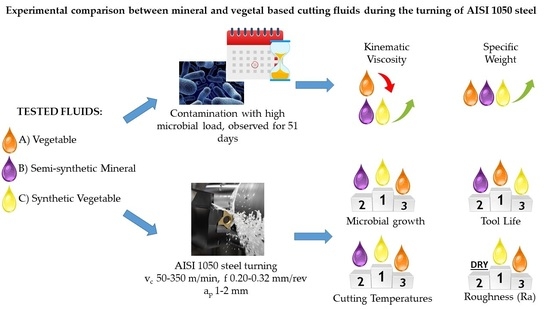
  • For the microbiological aging test, despite all the fluids having similar performance, CF-C had slightly better results, resisting more microbiological contaminations than CF-A and CF-B, because of the more efficient inter-fungi and bacterial additives in the formulation of these fluids.
  • Regarding tool life, CF-A had the best result, followed by CF-B and CF-C, with the dry cutting presenting the worst performance overall.
  • In general, the type and wear mechanisms observed were flank and crater wear, and the prevailing wear mechanisms were attrition and micro abrasion with the lowest cutting speed (200 m/min), and attrition, micro abrasion, and diffusion wear mechanisms under the highest cutting speed (350 m/min).
  • Regarding the average chip–tool interface temperatures, there are no significant differences for the lower cutting speeds, but for the highest cutting speed vc = 250 m/min, CF-C presented the best results (780 °C), followed by CF-B (820 °C), CF-A (880 °C), and dry condition (960 °C).
  • Concerning the surface roughness values after the first pass in the tool life tests, the CF-C presented the best results, followed by the dry machining, CF-A, and CF-B.
  • CF-A resulted in the longest tool life, good surface roughness, and good contamination stability, presenting the best overall performance.
In addition to the well-known environmental advantages in the production and maintenance of vegetable-based cutting fluids over mineral-based ones, the results presented here lead to the conclusion that vegetable-based cutting fluids can improve the machinability of material and permit a further step toward the development of a cleaner and sustainable machining process.

Author Contributions

Conceptualization, D.O.A.C. and Á.R.M.; Methodology, Á.R.M. and R.B.d.S.; Software, G.H.N.F.; Validation, E.S.C., P.H.P.F. and F.C.R.d.S.; Formal Analysis, L.R.R.d.S.; Investigation, L.R.R.d.S.; Resources, Á.R.M.; Data Curation, L.R.R.d.S.; Writing—Original Draft Preparation, D.O.A.C.; Writing—Review & Editing, L.R.R.d.S.; Visualization, L.R.R.d.S.; Supervision, Á.R.M.; Project Administration, Á.R.M.; Funding Acquisition, Á.R.M. All authors have read and agreed to the published version of the manuscript.

Funding

This research received no external funding.

Data Availability Statement

All the authors declare that this paper has no available data or material.

Conflicts of Interest

The authors declare no conflict of interest.

References

  1. Siju, A.S.; Gajrani, K.K.; Joshi, S.S. Dual textured carbide tools for dry machining of titanium Alloys. Int. J. Refract. Met. Hard Mater. 2021, 94, 105403. [Google Scholar] [CrossRef]
  2. Dhage, S.; Jayal, A.D.; Sarkar, P. Effects of surface texture parameters of cutting tools on friction conditions at tool-chip interface during dry machining of AISI 1045 steel. Procedia Manuf. 2019, 33, 794–801. [Google Scholar] [CrossRef]
  3. Kumar, C.S.; Majumder, H.; Khan, A.; Patel, S.K. Applicability of DLC and WC/C low friction coatings on Al2O3/TiCN mixed ceramic cutting tools for dry machining of hardened 52100 steel. Ceram. Int. 2020, 46, 11889–11897. [Google Scholar] [CrossRef]
  4. Fernandes, G.H.N.; Lopes, G.H.F.; Barbosa, L.M.Q.; Martins, P.S.; Machado, Á.R. Wear mechanisms of diamond-like carbon coated tools in tapping of AA6351 T6 aluminium alloy. Procedia Manuf. 2021, 53, 293–298. [Google Scholar] [CrossRef]
  5. Debnath, S.; Reddy, M.M.; Pramanik, A. Dry and near-dry machining techniques for green manufacturing. In Innovations in Manufacturing for Sustainability; Springer: Berlin/Heidelberg, Germany, 2019; pp. 1–27. [Google Scholar]
  6. Brown, W.L.; Butler, R.G. Metalworking fluids. In Synthetics, Mineral Oils, and Bio-Based Lubricants; CRC Press: Boca Raton, FL, USA, 2020; pp. 751–778. [Google Scholar]
  7. Ravi, S.; Gurusamy, P.; Mohanavel, V. A review and assessment of effect of cutting fluids. Mater. Today Proc. 2021, 37, 220–222. [Google Scholar] [CrossRef]
  8. Abbas, A.T.; Benyahia, F.; El Rayes, M.M.; Pruncu, C.; Taha, M.A.; Hegab, H. Towards optimization of machining performance and sustainability aspects when turning AISI 1045 Steel under different cooling and lubrication strategies. Materials 2019, 12, 3023. [Google Scholar] [CrossRef] [PubMed] [Green Version]
  9. Revuru, R.S.; Zhang, J.Z.; Posinasetti, N.R.; Kidd, T. Optimization of titanium alloys turning operation in varied cutting fluid conditions with multiple machining performance characteristics. Int. J. Adv. Manuf. Technol. 2018, 95, 1451–1463. [Google Scholar] [CrossRef]
  10. Trent, E.M.; Wright, P.K. Metal Cutting; Butterworth-Heinemann: Boston, MA, USA, 2000. [Google Scholar]
  11. Rodriguez, R.L.; Lopes, J.C.; Mancini, S.D.; de Ângelo Sanchez, L.E.; de Almeida Varasquim, F.M.F.; Volpato, R.S.; de Mello, H.J.; de Aguiar, P.R.; Bianchi, E.C. Contribution for minimization the usage of cutting fluids in CFRP grinding. Int. J. Adv. Manuf. Technol. 2019, 103, 487–497. [Google Scholar] [CrossRef]
  12. Gajrani, K.K.; Suvin, P.S.; Kailas, S.V.; Sankar, M.R. Hard machining performance of indigenously developed green cutting fluid using flood cooling and minimum quantity cutting fluid. J. Clean. Prod. 2019, 206, 108–123. [Google Scholar] [CrossRef]
  13. Kipling, M.D. Health Hazards from Cutting Fluids. Tribol. Int. 1977, 10, 41–46. [Google Scholar] [CrossRef]
  14. Irani, R.A.; Bauer, R.J.; Warkentin, A. A review of cutting fluid application in the grinding process. Int. J. Mach. Tools Manuf. 2005, 45, 1696–1705. [Google Scholar] [CrossRef]
  15. Ezugwu, E.O.; Da Silva, R.B.; Bonney, J.; Machado, Á.R. The effect of argon-enriched environment in high-speed machining of titanium alloy. Tribol. Trans. 2005, 48, 18–23. [Google Scholar] [CrossRef]
  16. Sales, W.F.; Guimarães, G.; Machado, Á.R.; Ezugwu, E.O. Cooling ability of cutting fluids and measurement of the chip-tool interface temperatures. Ind. Lubr. Tribol. 2002, 54, 57–68. [Google Scholar] [CrossRef]
  17. King, N.; Keranen, L.; Gunter, K.; Sutherland, J. Wet versus Dry Turning: A Comparison of Machining Costs, Product Quality, and Aerosol Formation; SAE Technical Paper; SAE International: Warrendale, PA, USA, 2001. [Google Scholar]
  18. Sanchez, J.A.; Pombo, I.; Alberdi, R.; Izquierdo, B.; Ortega, N.; Plaza, S.; Martinez-Toledano, J. Machining evaluation of a hybrid MQL-CO2 grinding technology. J. Clean. Prod. 2010, 18, 1840–1849. [Google Scholar] [CrossRef]
  19. Srikant, R.R.; Rao, P.N. Use of vegetable-based cutting fluids for sustainable machining in sustainable machining. In Sustainable Machining; Springer: Cham, Switzerland, 2017; pp. 31–46. [Google Scholar]
  20. Ozimina, D.; Kowalczyk, J.; Madej, M.; Nowakowski, Ł.; Kulczycki, A. The impact of the type of cutting fluid on the turning process. Tribologia 2018, 273, 119–126. [Google Scholar] [CrossRef]
  21. Shashidhara, Y.M.Ã.; Jayaram, S.R. Tribology international vegetable oils as a potential cutting fluid—An evolution. Tribol. Int. 2010, 43, 1073–1081. [Google Scholar] [CrossRef]
  22. Debnath, S.; Reddy, M.M.; Yi, Q.S. Environmental friendly cutting fluids and cooling techniques in machining: A review. J. Clean. Prod. 2014, 83, 33–47. [Google Scholar] [CrossRef]
  23. Siniawski, M.T.; Saniei, N.; Adhikari, B.; Doezema, L.A. Influence of fatty acid composition on the tribological performance of two vegetable-based lubricants. J. Synth. Lubr. 2007, 24, 101–110. [Google Scholar] [CrossRef]
  24. Paul, S.; Pal, P.K. Study of surface quality during high speed machining using eco-friendly cutting fluid. Mach. Technol. Mater. 2011, 11, 24–28. [Google Scholar]
  25. Araújo Junior, A.S.; Sales, W.F.; da Silva, R.B.; Costa, E.S.; Rocha Machado, Á. Lubri-cooling and tribological behavior of vegetable oils during milling of aisi 1045 steel focusing on sustainable manufacturing. J. Clean. Prod. 2017, 156, 635–647. [Google Scholar] [CrossRef]
  26. Osama, M.; Singh, A.; Walvekar, R.; Khalid, M.; Gupta, T.C.S.M.; Yin, W.W. Recent developments and performance review of metal working fluids. Tribol. Int. 2017, 114, 389–401. [Google Scholar] [CrossRef]
  27. Lawal, S.A.; Choudhury, I.A.; Nukman, Y. Developments in the formulation and application of vegetable oil-based metalworking fluids in turning process. Int. J. Adv. Manuf. Technol. 2013, 67, 1765–1776. [Google Scholar] [CrossRef]
  28. Xavior, M.A.; Adithan, M. Determining the influence of cutting fluids on tool wear and surface roughness during turning of AISI 304 austenitic stainless steel. J. Mater. Process. Technol. 2009, 209, 900–909. [Google Scholar] [CrossRef]
  29. Katna, R.; Suhaib, M.; Agrawal, N. Nonedible vegetable oil-based cutting fluids for machining processes—A review. Mater. Manuf. Process. 2020, 35, 1–32. [Google Scholar] [CrossRef]
  30. Souza, M.C.; Gonçalves, J.F.S.; Gonçalves, P.C.; Lutif, S.Y.S.; Gomes, J.O. Use of jatropha and moringa oils for lubricants: Metalworking fluids more environmental-friendly. Ind. Crops Prod. 2019, 129, 594–603. [Google Scholar] [CrossRef]
  31. Carvalho, D.O.A.; da Silva, L.R.R.; Sopchenski, L.; Jackson, M.J.; Machado, Á.R. Performance evaluation of vegetable-based cutting fluids in turning of AISI 1050 steel. Int. J. Adv. Manuf. Technol. 2019, 103, 1603–1619. [Google Scholar] [CrossRef]
  32. ASTM E2275-14; Standard Practice for Evaluating Water-Miscible Metalworking Fluid Bioresistance and Antimicrobial Pesticide Performance. ASTM International: West Conshohocken, PA, USA, 2014.
  33. ISO 3685; Tool-Life Testing with a Single-Point Turning Tools. International Organization for Standardization: Geneve, Switzerland, 1993.
  34. Santos, M.C.; Araújo Filho, J.S.; Barrozo, M.A.S.; Jackson, M.J.; Machado, A.R. Development and application of a temperature measurement device using the tool-workpiece thermocouple method in turning at high cutting speeds. Int. J. Adv. Manuf. Technol. 2017, 89, 2287–2298. [Google Scholar] [CrossRef]
  35. Marques, A. Torneamento de Inconel 718 Com Aplicação de Lubrificantes Sólidos. Ph.D. Thesis, Universidade Federal de Uberlândia, Uberlândia, Brazil, 2015. (In Portuguese). [Google Scholar]
  36. Grossi, M.; Parolin, C.; Vitali, B.; Riccò, B. A Portable sensor system for bacterial concentration monitoring in metalworking fluids. J. Sens. Sens. Syst. 2018, 7, 349–357. [Google Scholar] [CrossRef] [Green Version]
  37. Finzi, M. Microbioma do Fluido de Corte Utilizado na Indústria Metal-Mecânica Brasileira: Composições Quantitativa e Qualitativa, Fatores que Influenciam a Presença de Microrganismos, Biodegradação e Impacto nas Propriedades Lubri-Refrigerante. Ph.D. Thesis, Universidade Federal de Uberlândia, Uberlândia, Brazil, 2015. (In Portuguese). [Google Scholar]
  38. Ozcelik, B.; Kuram, E.; Huseyin Cetin, M.; Demirbas, E. Experimental investigations of vegetable based cutting fluids with extreme pressure during turning of AISI 304l. Tribol. Int. 2011, 44, 1864–1871. [Google Scholar] [CrossRef]
  39. Jozić, S.; Vrsalović, L.; Bajić, D.; Gudić, S. Investigation of different cutting conditions in the machining of steel—Towards cleaner production. J. Clean. Prod. 2022, 356, 131881. [Google Scholar] [CrossRef]
  40. Ogedengbe, T.S.; Awe, P.; Joseph, O.I. Comparative analysis of machining stainless steel using soluble and vegetable oils as cutting fluids. Int. J. Eng. Mater. Manuf. 2019, 4, 33–40. [Google Scholar] [CrossRef]
Figure 1. Microstructure of the AISI 1050 steel etched with Nital 2% for 15 s.
Lubricants 10 00309 g001
Figure 2. Experimental methodology used in the investigation.
Lubricants 10 00309 g002
Figure 3. Plates with bacteria: Left: Samples with three different bacterium types; Center: sample with an uncountable number of bacteria (dilution is necessary); and Right: sample with two types of bacteria.
Lubricants 10 00309 g003
Figure 4. Schematic drawing of the temperature measuring system using the tool–workpiece thermocouple method. Adapted from Marques [35].
Lubricants 10 00309 g004
Figure 5. Calibration curves of the workpiece/tool thermocouple.
Lubricants 10 00309 g005
Figure 6. Microbial growth of the cutting fluids for 51 days for the three cutting fluids investigated at the concentration of 7%.
Lubricants 10 00309 g006
Figure 7. Kinematic viscosity (mm2/s) and a specific weight (g/cm3) of fluids A, B, and C before and after contamination by microbiological organisms for 51 days.
Lubricants 10 00309 g007
Figure 8. Tool wear against time curves obtained under the four cutting conditions tested.
Lubricants 10 00309 g008
Figure 9. Comparison of tool lifetimes in each cutting condition.
Lubricants 10 00309 g009
Figure 10. Views of the flank wear of the tools used under the various cutting atmospheres tested after 30 min of cut for condition 1, vc = 200 m/min, f = 0.2 mm/rev, and ap = 2 mm. (a) Cutting fluid A; (b) Cutting fluid V; (c) Cutting fluid C; (d) Dry machining.
Lubricants 10 00309 g010
Figure 11. Views of the worn areas of the tool used under the cutting condition 1, vc = 200 m/min, f = 0.2 mm/rev, and ap = 2 mm cutting fluid A.
Lubricants 10 00309 g011
Figure 12. Details of the wear on the tool’s rake face used under cutting condition 2, vc = 200 m/min, f = 0.32 mm/rev and ap = 2 mm, and cutting fluid A.
Lubricants 10 00309 g012
Figure 13. Flank faces of the tools used under cutting condition 2, vc = 200 m/min, f = 0.32 mm/rev, and ap = 2 mm for all the lubri-cooling atmospheres tested. (a) Cutting fluid A; (b) Cutting fluid V; (c) Cutting fluid C; (d) Dry machining.
Lubricants 10 00309 g013
Figure 14. Flank faces of the tools used under cutting condition 3, vc = 350 m/min, f = 0.2 mm/rev, and ap = 2 mm, for all the lubri-cooling atmospheres tested. (a) Cutting fluid A; (b) Cutting fluid V; (c) Cutting fluid C; (d) Dry machining.
Lubricants 10 00309 g014
Figure 15. Details of the crater wear of the tool used under cutting condition 3, vc = 350 m/min, f = 0.2 mm/rev and ap = 2 mm, and cutting fluid A.
Lubricants 10 00309 g015
Figure 16. Views of the flank worn surfaces of tools used under cutting condition 4, vc = 350 m/min, f = 0.32 mm/rev, and ap = 2, for all the lubri-cooling atmospheres tested. (a) Cutting fluid A; (b) Cutting fluid V; (c) Cutting fluid C; (d) Dry machining.
Lubricants 10 00309 g016
Figure 17. Rake face of the tool used under the cutting condition 4, vc = 350 m/min, f = 0.32 mm/rev and ap = 2 mm, and cutting fluid C.
Lubricants 10 00309 g017
Figure 18. Rake face of the tool used under the cutting condition 4, vc = 350 m/min, f = 0.32 mm/rev and ap = 2 mm, and dry condition.
Lubricants 10 00309 g018
Figure 19. Temperatures x cutting speed using the tool/piece thermocouple method in f = 0.20 mm/rev and ap = 1 mm.
Lubricants 10 00309 g019
Figure 20. Roughness (Ra) measurements taken for the tool’s first usage considering the four cutting conditions.
Lubricants 10 00309 g020
Table 1. Chemical composition of steel ABNT 1050 (%wt.).
CMnSiPCuSCrNiMoSn
0.520.7300.240.0130.080.0220.150.110.030.008
AlVNbTiBCaAsONFe
0.0160.020.0010.00090.00040.00060.00312 ppm83 ppmBalance
Table 2. Typical mechanical properties of ABNT 1050 steel. Adapted with permission from [31].
Specific Weight
ρ ton/m3
Young Modulus
E (GPa)
Shear Modulus
G (GPa)
Ultimate StrengthElongation
Percent
ε (%)
Coefficient. of Thermal Expansion
α (10−6 C−1)
Vickers Hardness
HV (400 N)
Tensile
σ (MPa)
Shear
τ (MPa)
7.86210803402001511.7255
Table 3. Composition of the three cutting fluids tested.
Cutting FluidCompound’s Name%
AEsters of phosphoric acid and neutralized amine≥6~<10
Triethanolamine≥5~<10
Fatty acids, tall oils, ethoxylates≥5~<10
N,N′-methylenebisismorpholine alcohols≥3~<5
3-iodo-2-propynyl butylcarbamate≥0.3~<1
BBasic oil–highly refined15~20
N,N-methylene bismorpholine5~10
Triethanolamine5~10
Esters of phosphoric acid and neutralized amine1~5
Amino-neutralized amine carboxylic acids1~5
2-aminoethanol1~5
2-Methylpentane-2,4-diol0.1~1
CTriethanolamine20~25
N,N-methylene bismorpholine1~5
Table 4. According to the manufacturer, the classification and main properties of the three cutting fluids were tested.
FluidFluid A–An Emulsion of Vegetable BaseFluid B–Semisynthetic of Mineral BaseFluid C–Synthetic Vegetable Base
Properties
General characteristicsBio-stable with anticorrosion properties; anti-foaming; free from boron, nitrites, and phenols; contains corrosion inhibitors, fatty acids, synthetic lubricants, and bactericide.A chemical blend contains highly refined mineral oils, water, emulsifiers, performance additives, and biocides.Bio-stable with anticorrosion properties; anti-foaming, free from boron, chlorinated paraffin, nitrites, and phenols; anti-corrosive, synthetic lubricants, and bactericide.
pH (5% solution)9.19.59.2
Boiling pointabove 100 °C
FlashpointWater-based product (not inflammable)
Density at 20 °C (g/mL)1.0711.0201.060
SolubilityWater soluble
Table 5. Machining parameters used for the tool’s life analysis.
Conditionsvc (m/min)f (mm/rev)
12000.20
22000.32
33500.20
43500.32
Publisher’s Note: MDPI stays neutral with regard to jurisdictional claims in published maps and institutional affiliations.

