3.1. Microstructure of AA7075-SiC/Gr Composites
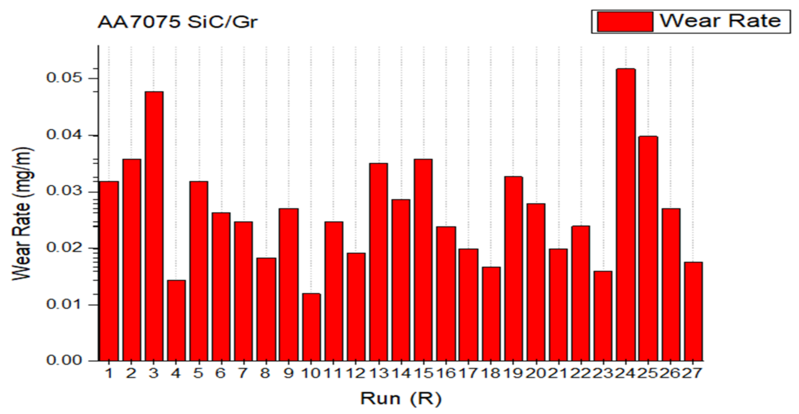
In the present study, a total of 27 SiC/Gr surface composites samples (S1–S27) were fabricated as per the response surface central composite design using Design Expert 10. The 27 samples processed with designed parameters and their microhardness and wear rates have been reported. Amongst these 27, the S-24 sample (processed at rotational speed-500rpm, traverse speed-20 mm/min, hybrid ratio of SiC/Graphite-60:40, volume percentage-12) and S-10 (processed at rotational speed-1500 rpm, traverse speed-40 mm/min, hybrid ratio of SiC/Graphite-60:40 and volume percentage-4), hybrid composites showed the highest (0.05175 mg/m) and lowest wear rate (0.01194 mg/m), respectively. Samples were cut and examined in this work for further microstructure investigation. The microstructure samples were prepared, and after etching, the imaging of the processed zone carried out using OM and SEM.
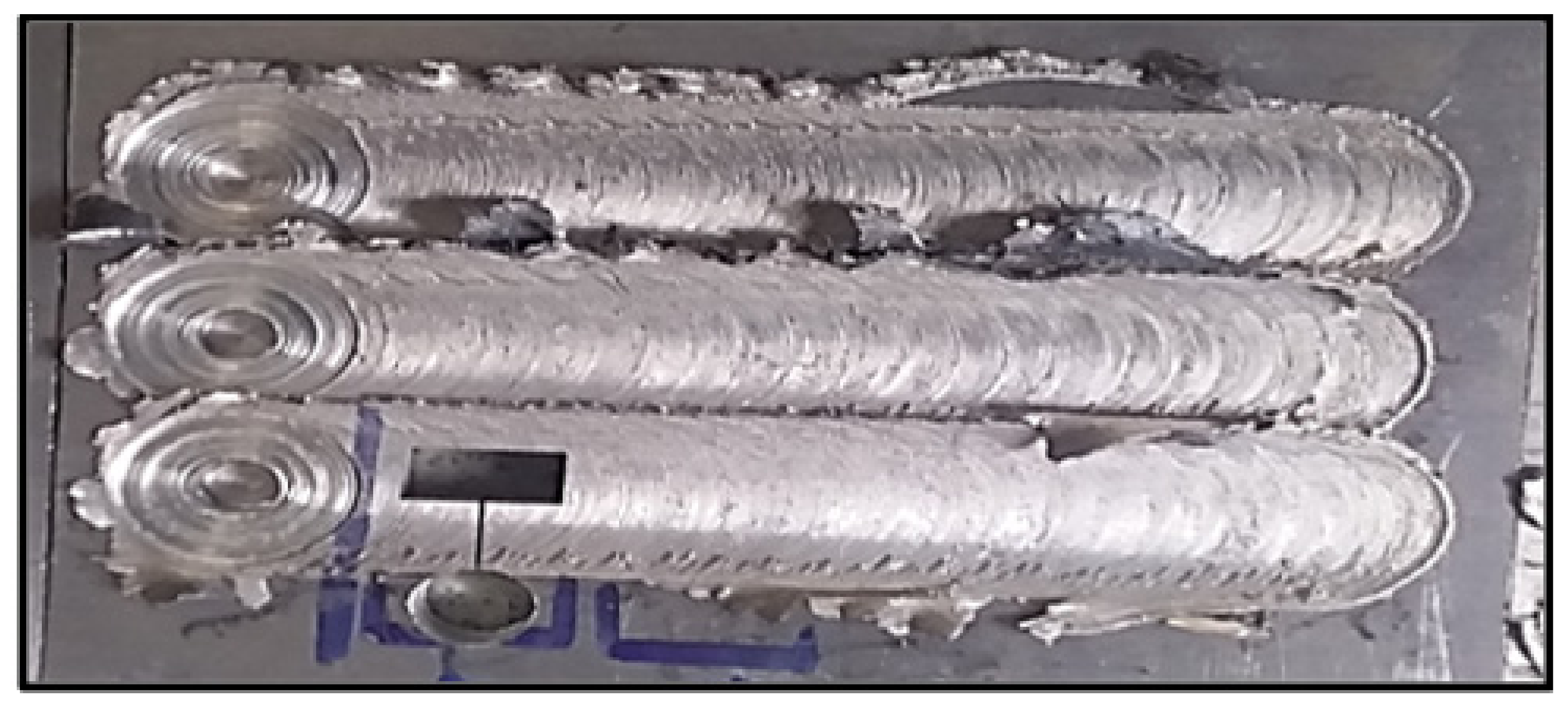
The micrographs obtained are observed carefully to understand the SiC/Gr nanoparticles’ distribution, the movement of particles with plasticized metal during the processing, and the dispersion regions with low, medium, and highly dense SiC/Gr particles presence. The morphology of the AA7075-SiC-graphite composites has been shown in
Figure 2. The onion rings on the surface composites are observed. Three composite bands were produced for every run of L27 combinations. The wear sample was cut from the middle of the band as shown in
Figure 2. The
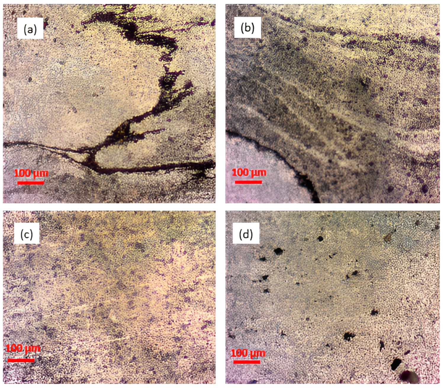
Figure 3 and
Figure 4 show the optical imaging micrographs of run S-10 and run S-24 surface composite’s stir zone region. From the optical micrographs, it is observed that the SiC/Gr nanoparticles’ distribution inside the stir zone is governed by the resultant plasticized material movement during processing. Thus, bands with various particle presences are seen in the SZ areas. For S-10 composite,
Figure 3a denotes the SiC-Gr particles moderate agglomeration in reverse s-shape area, and in other regions, it looks well distributed. Similarly, the SiC/Gr particles’ distribution looks good and homogenous, as presented in
Figure 3b–d. The S-10 composite band has been produced for the volume percentage of 4% and with the speed of 1500 rpm. Due to the high rotating speed, the SiC/Gr particles are now mainly uniformly spread with a few small dense clusters. The re-fined equiaxial fine grains’ structure is a result of the grain size refinement, which was caused by the uniform distribution of SiC/Gr particles.
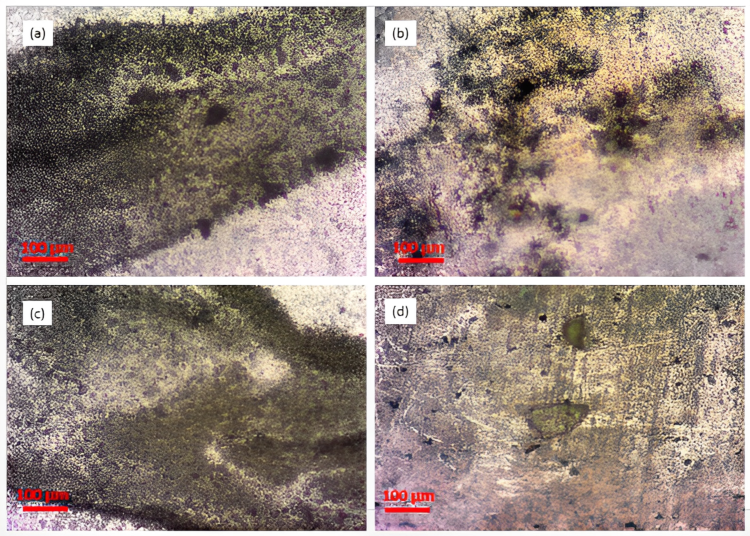
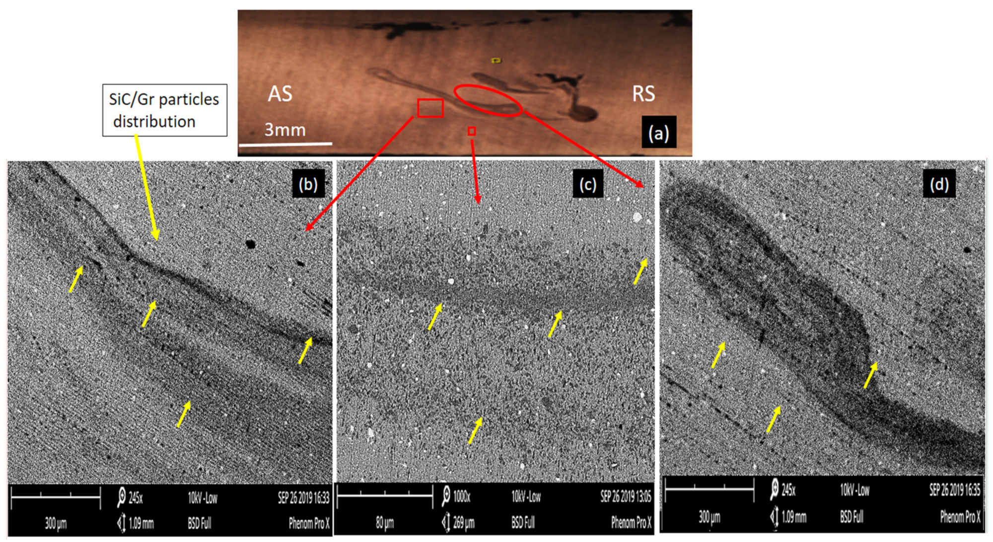
Figure 4 depicts the particle distribution within the composite’s stir zone after processing in the case of the S-24 composite. When compared to the S-10 composite, it has been shown that the particles are more densely distributed inside the aluminum matrix. The dense clusters of SiC/Gr particles have led to the porosity around the agglomerates, as shown in
Figure 4b. The highly dense regions are observed in
Figure 4a,c,d images. Here, in the S-24 composite, the tool rotational speed used is 500 rpm at 20 mm/min traverse for the volume percentage of 12% SiC/Gr. Thus, the extent of plastic deformation during the processing was not enough to give particles homogenous distribution within the matrix. The flow stress of the basic aluminum alloy must be greatly exceeded by the level of plasticization; only then would the dispersion have occurred more evenly. The high-volume percentage of SiC/Gr mixture was found to be difficult to disperse uniformly within the matrix band with lower stirring rotational speed.
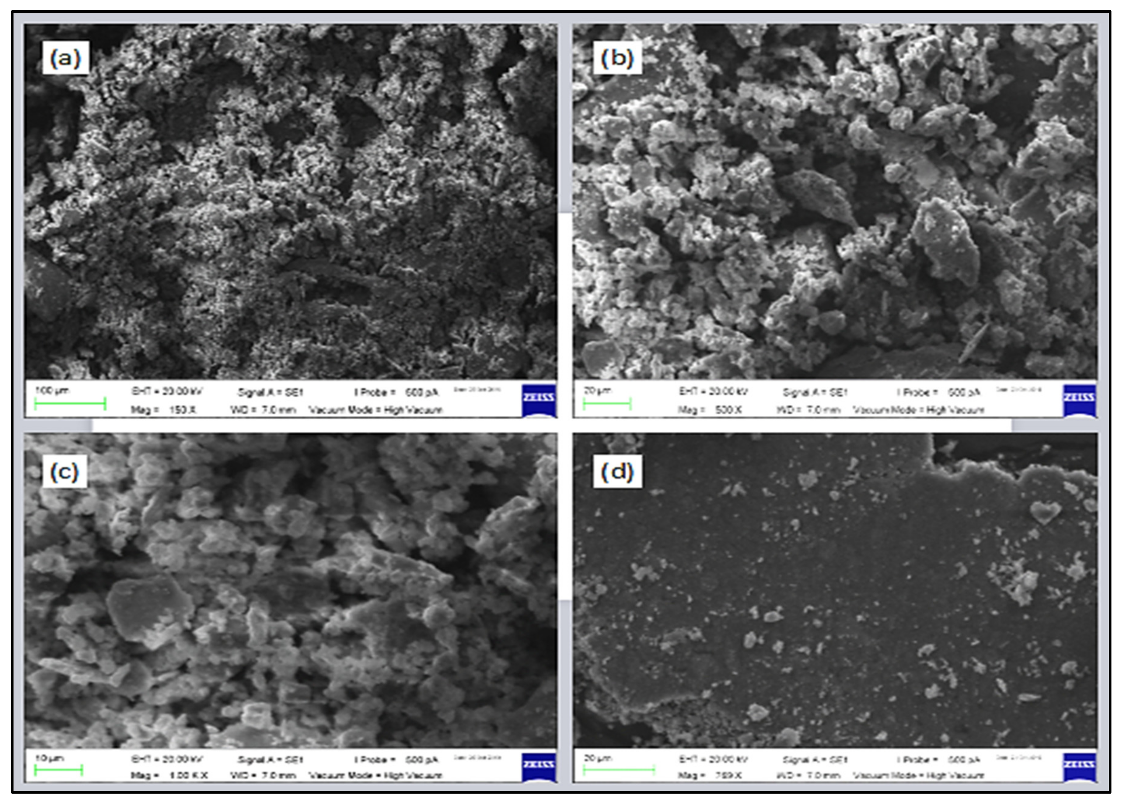
In the
Figure 5, SEM micrographs of Al7075-SiC/Gr composites from the S-24 sample that have been enlarged to demonstrate the SiC/Graphite particle dispersion inside the base alloy. The composite’s stir zone (SZ) area is shown by the macrographs in
Figure 5a and
Figure 6a. The plasticized material in the FSP typically moves from the advancing side (AS) to the retreating side (RS). The highly dense particle agglomerated zones are seen in the macrograph as green oval shape outlines. Due to weak interfacial bonding with the base alloy under surface-to-surface stress conditions, these zones are possible locations where the particles might break away. The porosity is also shown by the particles over agglomerated zones as a drawback. Particle agglomerates cause the formation of spheroids, which serve as locations for porosity and loose interfacial bonding areas where particle detachment may occur during surface loading.
The micrographs of
Figure 5 show the variation in the SiC/Gr particles’ dispersion within the stir zone. Due to the variable plasticized material movement during FSP, the resultant particle distribution varies in nature. Yellow arrow marks denote the particles clusters in the micrographs. It is observed that the material movement was prominent in the central part of the stir zone, however on the bottom side of retreating sides and advancing side’s top portion, the material movement during plasticization was not enough to force the particles evenly in the composite band. It can be easily observed that the particles have moved from AS to RS and have gathered in the RS below half portion. At the top portion of the SZ, the forging action of the FSP tool was prominent to allow the generated intense plasticization to disperse the particles uniformly. Still, the material movement was not enough to get homogenous distribution on the lower side of the tool pin. Thus, the mismatch in the amount of SiC/Gr powder to be dispersed and the extent of plasticization that took place led to the agglomerated zones inside the composite.
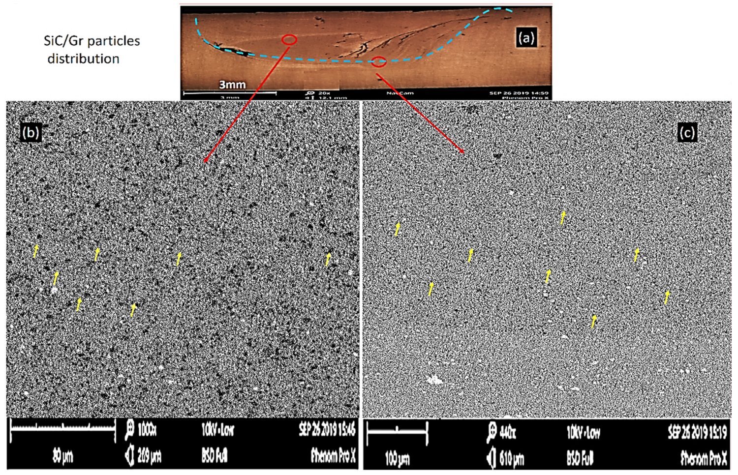
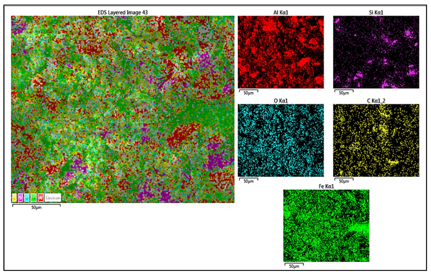
For the S-10 composite, the SEM micrographs are shown in
Figure 6, where the particle distribution within the band stir zone is observed. The macrograph of the processed zone depicts that the SiC/Gr reinforcement particles have distributed comparatively well in comparison to the S-24 composite. Only at the AS bottom, the small agglomerates are observed. On the retreating side, the particles agglomerations have not been regarded as like the S-24. The stirring action in the case of run S-10 was found to be intense enough to overcome the aluminum base alloy’s flow stress and smoothened the particles’ dispersion within the plasticized zones. Different areas on the bands have been observed using SEM, as shown in
Figure 5 and
Figure 6, respectively. The yellow arrows indicate the SiC/Gr particles’ dispersion agglomerates and continuous bands.
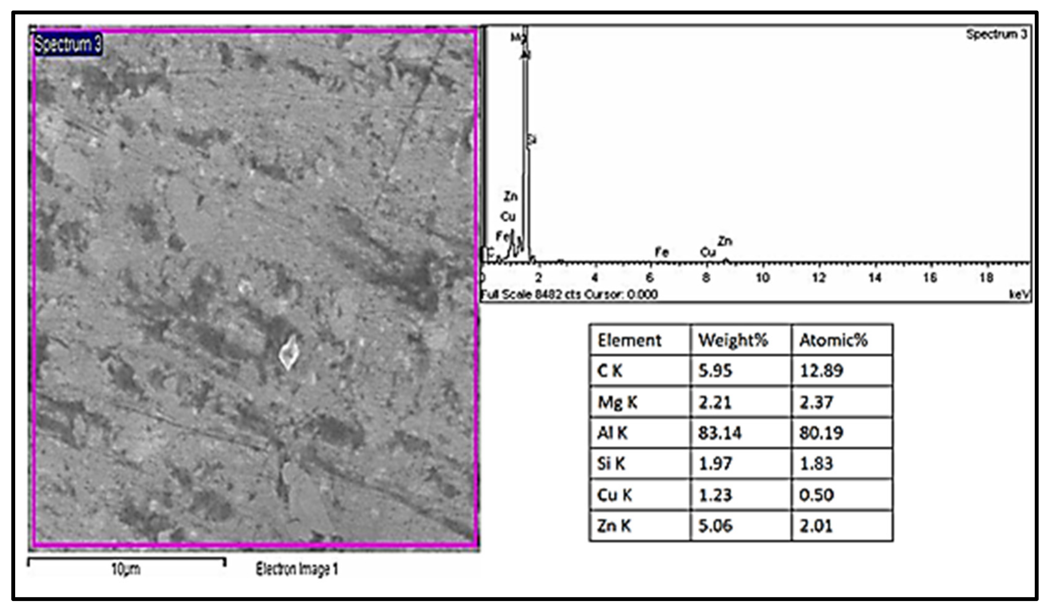
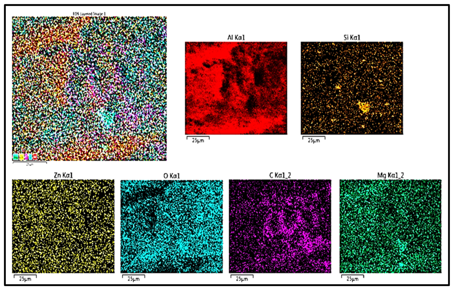
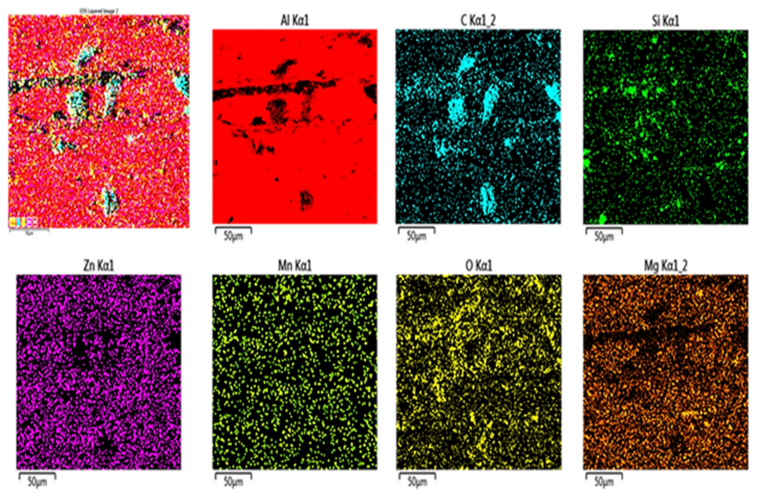
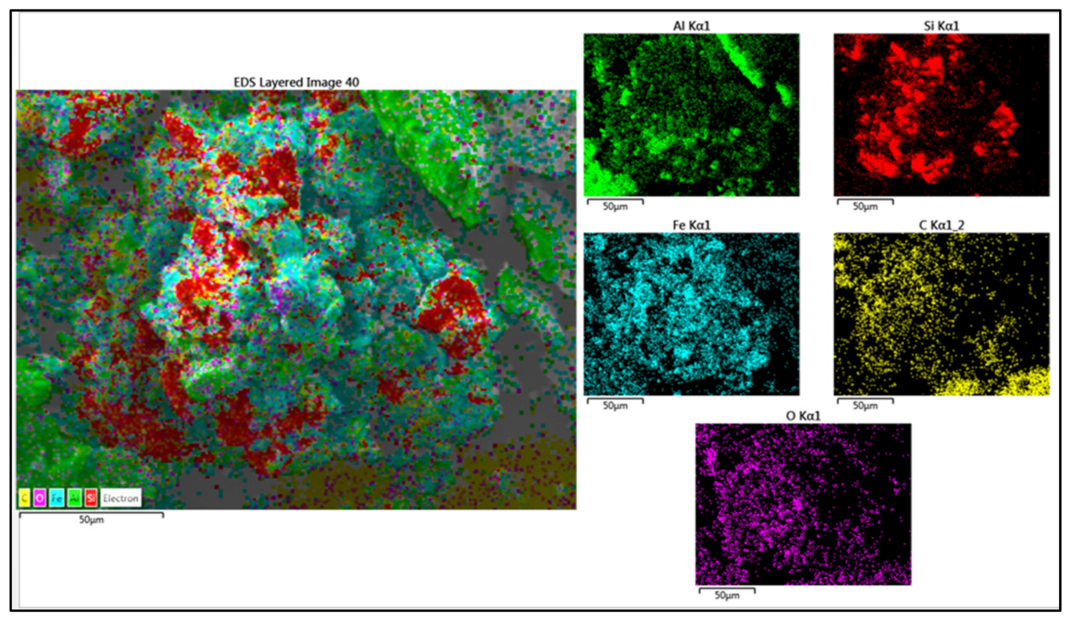
In both the composites of the S-10 and S-24, at the interface of the reinforced and unreinforced zones, the change in the microstructure has been observed. The reinforced zone indicates the presence of SiC hard particles with graphite nanosheets dispersed around and also the inherent insoluble constituent phases and soluble precipitates, whereas in the case of the unreinforced/particles free processed zone, the inherent isomorphous precipitates and insoluble constituent phases are present. The constituent phases are micron-sized s, and an oval shape can be observed more clearly compared to the isomorphous phases in nanoscales. The presence of SiC-graphite particles has been confirmed through EDS and mapping analysis as shown in
Figure 7 and
Figure 8, respectively.
Due to the very fast rotating, stirring action used in the S-10 composite, the SiC/Gr powders were well dispersed, and there was enough time to encapsulate the graphitic layers surrounding the SiC particles. The shear force during vigorous plasticization causes the graphite flakes to be exfoliated into multilayer graphene [
32,
33]. Due to the enormous surface area that graphite flakes naturally possess, they have a substantial coverage in the composites. Due to the severe plasticization, the SiC particles that break in both samples have fractured into varying sizes. The base alloy and the SiC/Gr reinforcements are connected by the exfoliated graphitic layers, which have improved interfacial bonding. The hybrid ratio of graphite is limited to a maximum of 40% due to the material’s very high heat conductivity, since amounts of Gr over this limit have caused tattering faults in the composite bands [
33].
In contrast to the S-24 composite sample, the graphitized SiC particles in the S-10 sample are shown to have better interfacial bonding. Due to a more vigorous stirring action, the S-10 composite sample has more graphite layers encasing the SiC particles than the S-24 sample. The hybrid ratio of 60:40 is employed in both samples but run S-10’s extreme plasticization caused by its fast-rotating speed made it easier to overcome the base alloy’s flow stress, which led to an increase in the mobilization of particles within the matrix. The mobility and dispersion of the particles during the stirring action were constrained by the higher volume percentage (12%) of SiC/Gr powder and lower rotating speed (500 rpm) in S-24. On the other hand, the high rotating speed (1500 rpm) and low volume % of the SiC/Gr powder have enabled substantial particle mobility and dispersion in the matrix.
The Al 7075-SiC/Gr composites have a higher surface area covered by the very thin graphite flakes. The SiC particles have also been broken up and disseminated throughout the composites at the same time. The machine settings and reinforcement dispersion affected how the composite surfaces looked. The resulting grain size achieved within the composites has been impacted by the SiC/Gr reinforcement particles dispersion inside the matrix. Due to the presence of reinforcements, the pinning effect primarily regulates the grain development in treated composites. As a consequence, the resulting surface composites have a finer grain structure thanks to the encapsulation of reinforcements during severe plasticization. In the instance of the S-24 composite, it can be seen that the SiC/Gr particle interfaces suggest the potential for porosity surrounding them owing to poorer interfacial bonding.
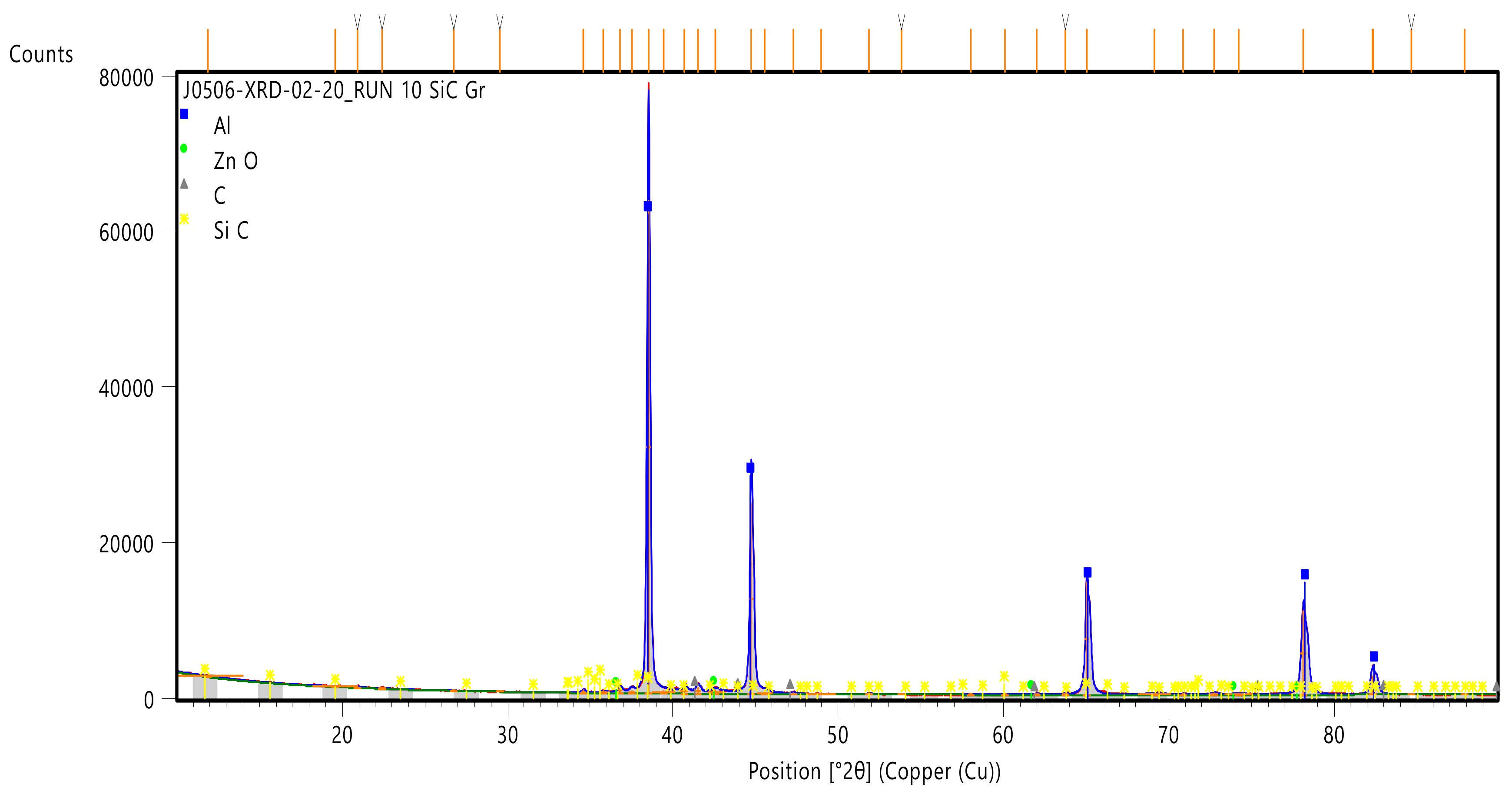
It’s confirmed that the S-10 composite surface contains SiC, Graphite, and ZnO inside the aluminum base alloy as shown in
Figure 9. The base alloy Al shows peaks at 2θ = 8.46° with 100% match I% with [
34]. The aluminum with cubic crystalline structure with indices (111) with an interlayer spacing of 2.3381 A° is observed, matching with the base alloy results. The rhombohedral crystal structure for SiC has been observed at a peak of 35.621°, d-spacing 2.5183 A° which matches 100% with the results from [
35]. Many small peaks were present, indicating the SiC particles’ presence with different intensities, e.g., at 60.047° at 73 I%, 37.84° at 73.4 I%, 38.48° at 56.9 I%, etc. with the same rhombohedral crystal structure with different Miller indices.
The graphite content is indicated in terms of hexagonal crystal structured at 41.337° with (100) indices, which matches with the results in the system from [
36]. The main graphite peak appears at 2θ of 26.5°. Like SiC, the graphite has also shown different intensity small peaks at various angles. The zinc oxide ZnO presence has also been confirmed in the analysis with the peak at 42.496°. The ZnO can be formed during processing by the reaction between the Zn in the form of precipitates with the atmospheric air. ZnO can also be observed between the surface-to-surface dry sliding actions as the isomorphous precipitates could react with the atmospheric oxygen to form the oxide film.
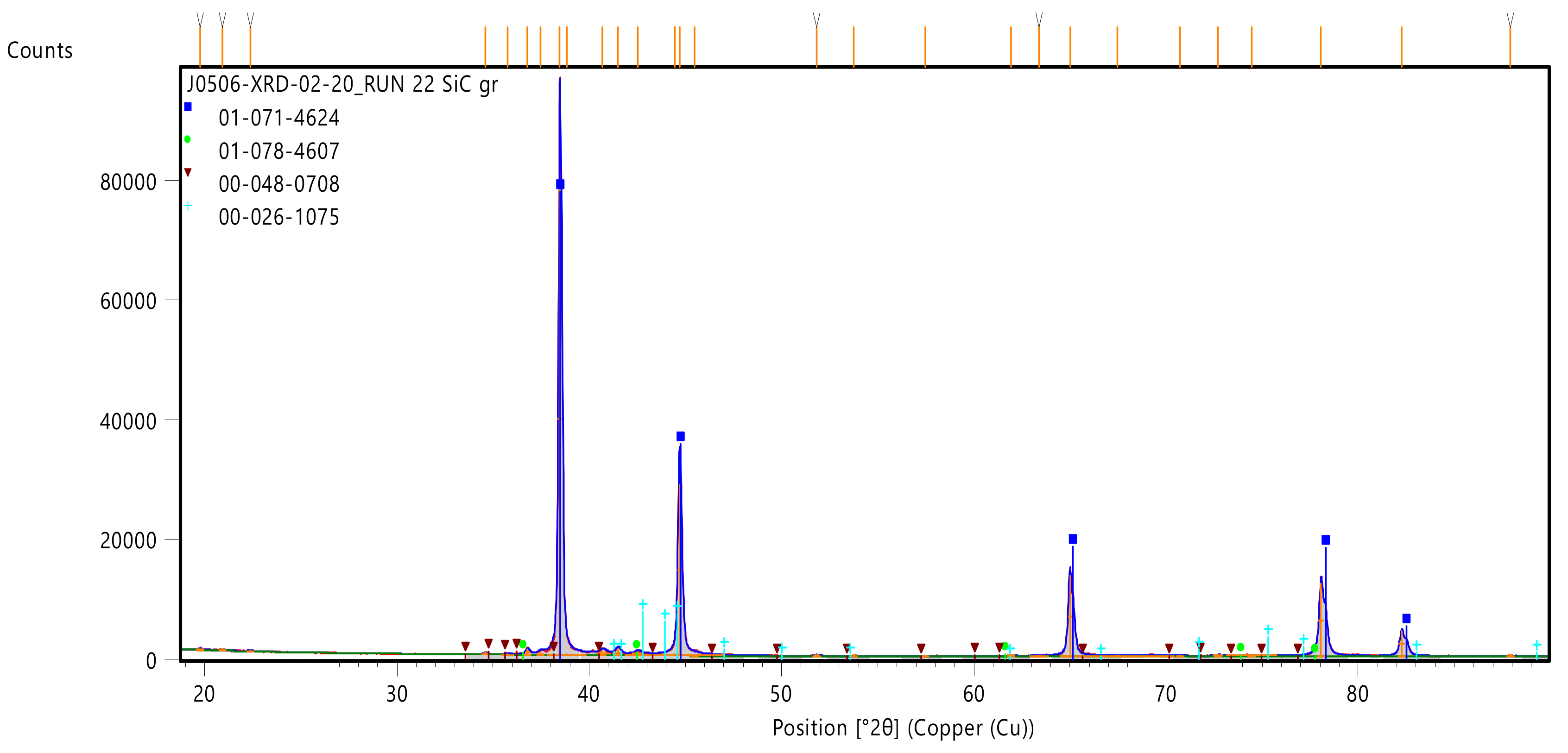
In S-24, the aluminum peak was observed at 38.508° with I%-100, with the cubic crystal structure (111) and interlayer d-spacing (2.335 A°) minimally lowered compared to the S-10 composite, as shown in
Figure 10. The SiC crystal structure was found to be hexagonal with a 36.222° peak with 100% intensity, d-spacing of 2.478 A°, and other peaks with different intensities and miller indices. Here, the d-spacing of the SiC crystal structure looks lower than the S-10. The graphite with a hexagonal crystal structure shows the peak at 42.803° with 100.0 match intensity. The d-spacing again in this S-24 case is lower than the S-10 sample. The ZnO presence was again found with the d-spacing 2.125, peak at 2θ angle of 42.496°. Thus, from the XRD results, the SiC/graphite embedding inside the composite is confirmed with some oxide layer formation on the surface.
3.2. Wear Properties of AA7075-SiC/Gr Composites
The wear rate in mg/m for all of the L27 runs are represented in the bar graph as shown in
Figure 11. The wear resistance has improved overall for the Al 7075-SiC/Gr samples compared to the base alloy. Under dry sliding circumstances, the wear rates of the surface composites were calculated using a Pin-on-Disc tribometer. The results of the wear are encouraging and have shown the significant effect of embedding the hard SiC and soft solid lubricant graphite nanoflakes on the surface behavior of the composites under dry sliding conditions, with this being different to the fretting wear behavior of the base alloy.
3.2.1. Wear Tracks Analysis of AA7075-SiC/Gr Composites
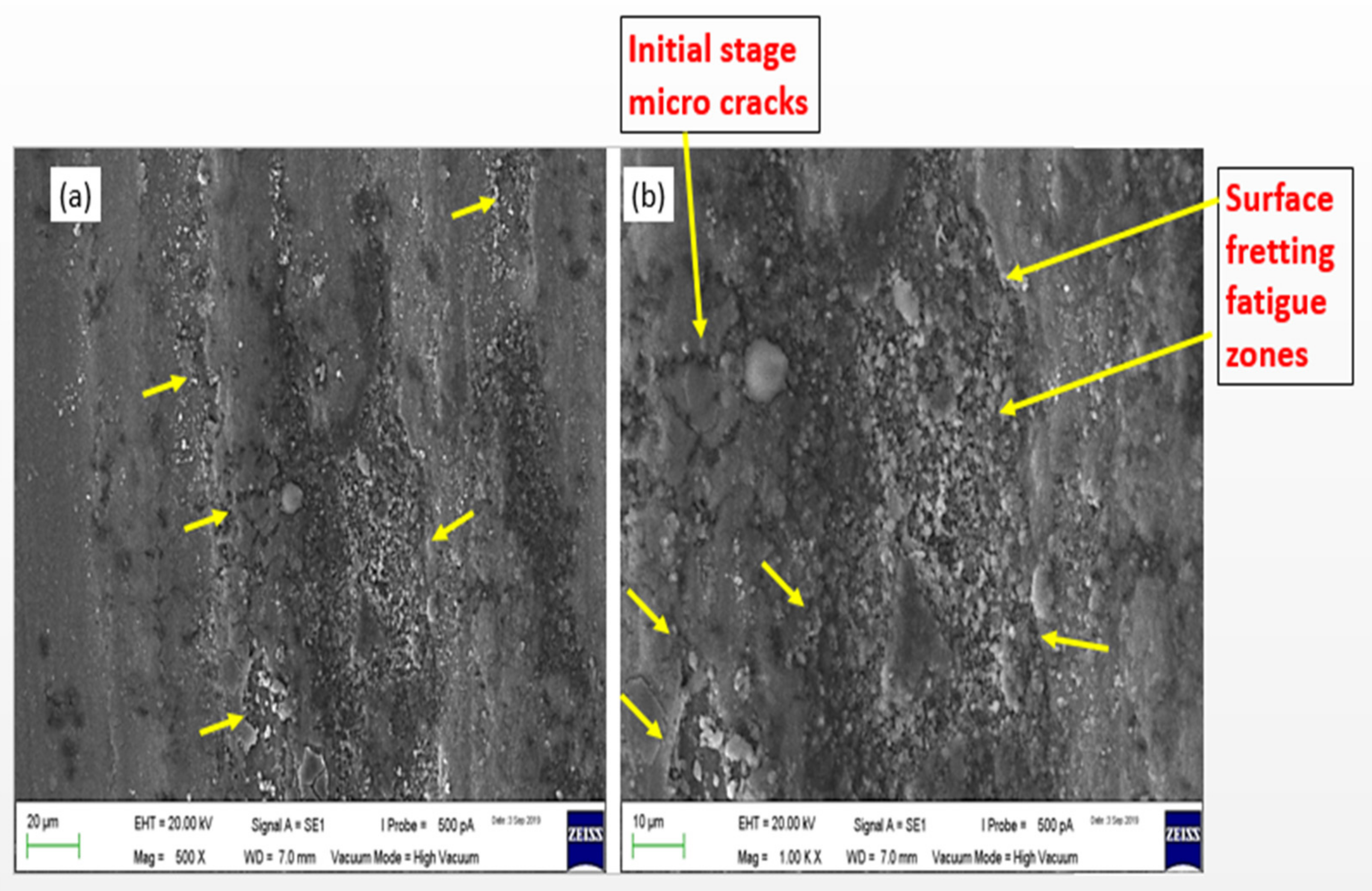
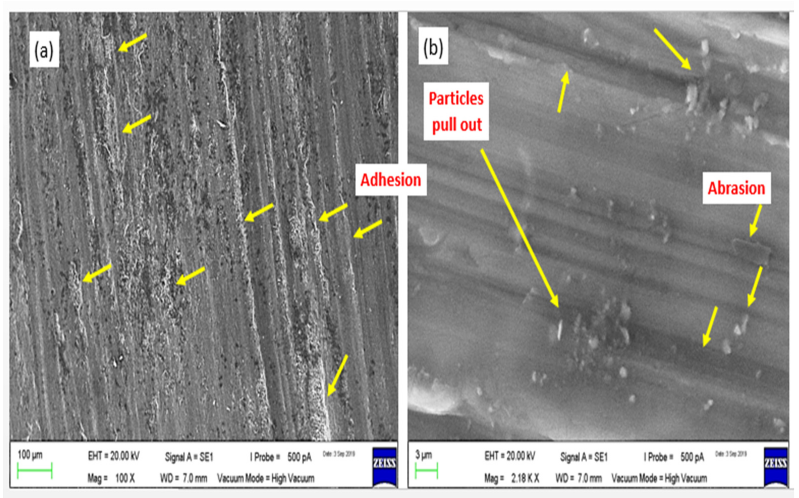
Figure 12 and
Figure 13 show the wear tracks on the pins of base alloy AA7075-T6. The surface fatigue and resulting fretting wear taking place can be observed on the surface wear tracks. Mainly, the precipitates’ dense zones have been found to be prone for the fretting fatigue wear nucleation sites. From the images of the tracks, it can be observed that the dark black colors are the inherent isomorphous precipitates and the constituent phases zones, upon which repeated cycling loading among the asperities of the mating materials start showing symptoms of the fatigue micro cracks, which then subsequently convert into the crater area of the loose debris. The debris particles pulled out again have churned and acted as the abrasive medium between the mating materials, which led to the small abrasion lines. Along the parallel tracks of the dry sliding wear, tiny pits started to develop as a result of the adhesion caused by localized plastic flow, which was also seen on the surface. The adhesion and fretting fatigue wear were found to be prominent mechanisms responsible for the wear of the AA7075-T6 alloy samples.
For the S-10 composite, the wear tracks are as shown in
Figure 14 and
Figure 15. The delamination, and fatigue tendency has been observed over the surface as shown in
Figure 15. The EDX and mapping of the sample-area shown in
Figure 14 are presented in
Figure 16 and
Figure 17, respectively. Analysis of the S-10 composite’s wear track has confirmed the existence of mating steel disc particles and SiC/Gr reinforcement particles.
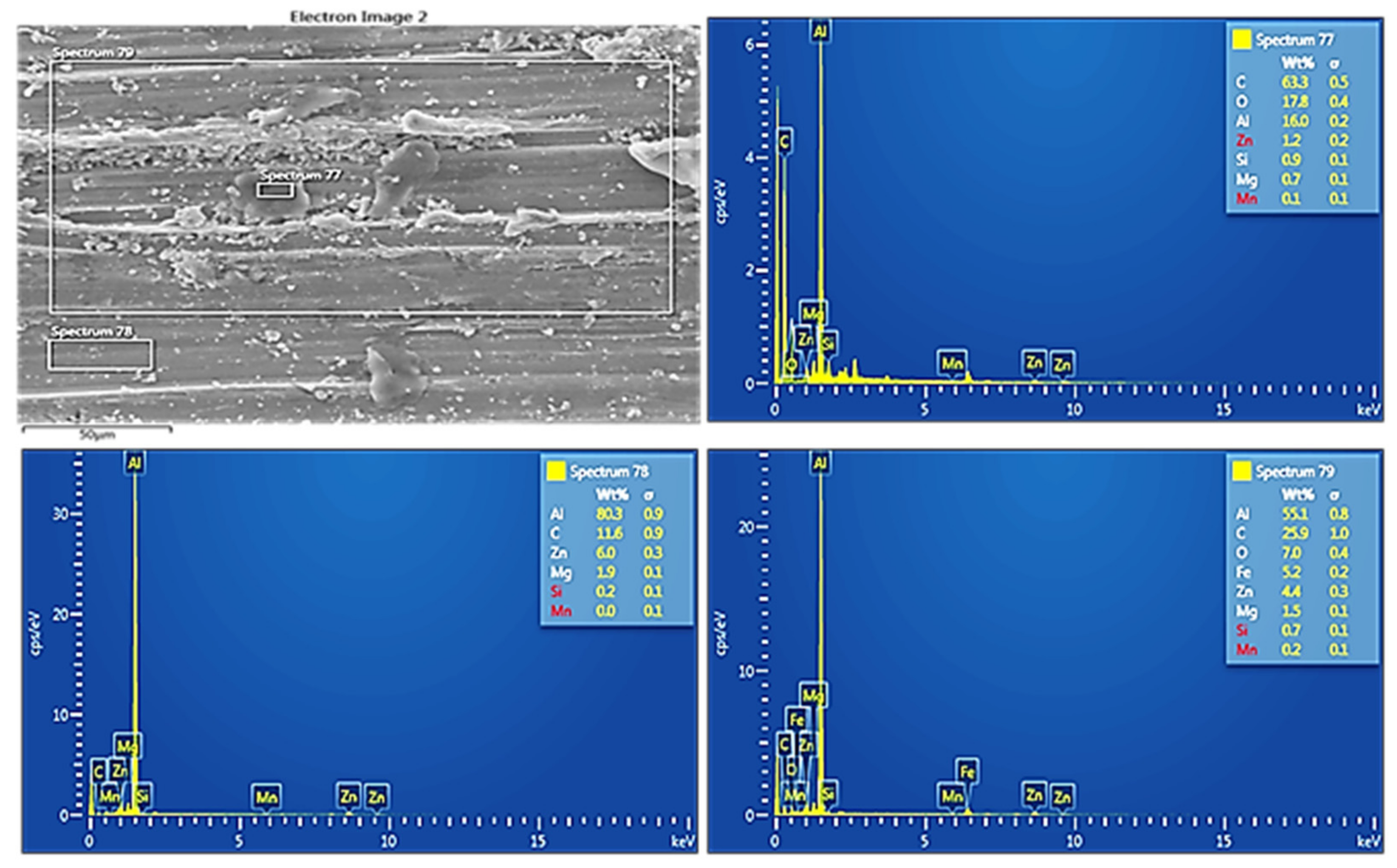
Figure 16 in the following text displays the SEM EDX analysis for such confirmation. The wear track has dark patches that are consistent with the graphitized SiC particles seen in spectrum77 in
Figure 16. The presence of the most carbon (C) shows that the areas with SiC/Gr reinforcements are those.
As illustrated in
Figure 16, the somewhat dark uniform region supports the existence of a thin graphitic tribofilm since the spectrum78 reveals the presence of C close to the aluminum alloy. The spectrum79, which finally covered the whole track surface within its view, confirmed the presence of SiC/Gr reinforcement and small amounts of steel disc particles as ferrous (Fe) elements. The SiC particles and Graphite flakes forming the mechanically mixed layer over the run S-10 sample surface have been confirmed through the SEM mapping analysis as shown in
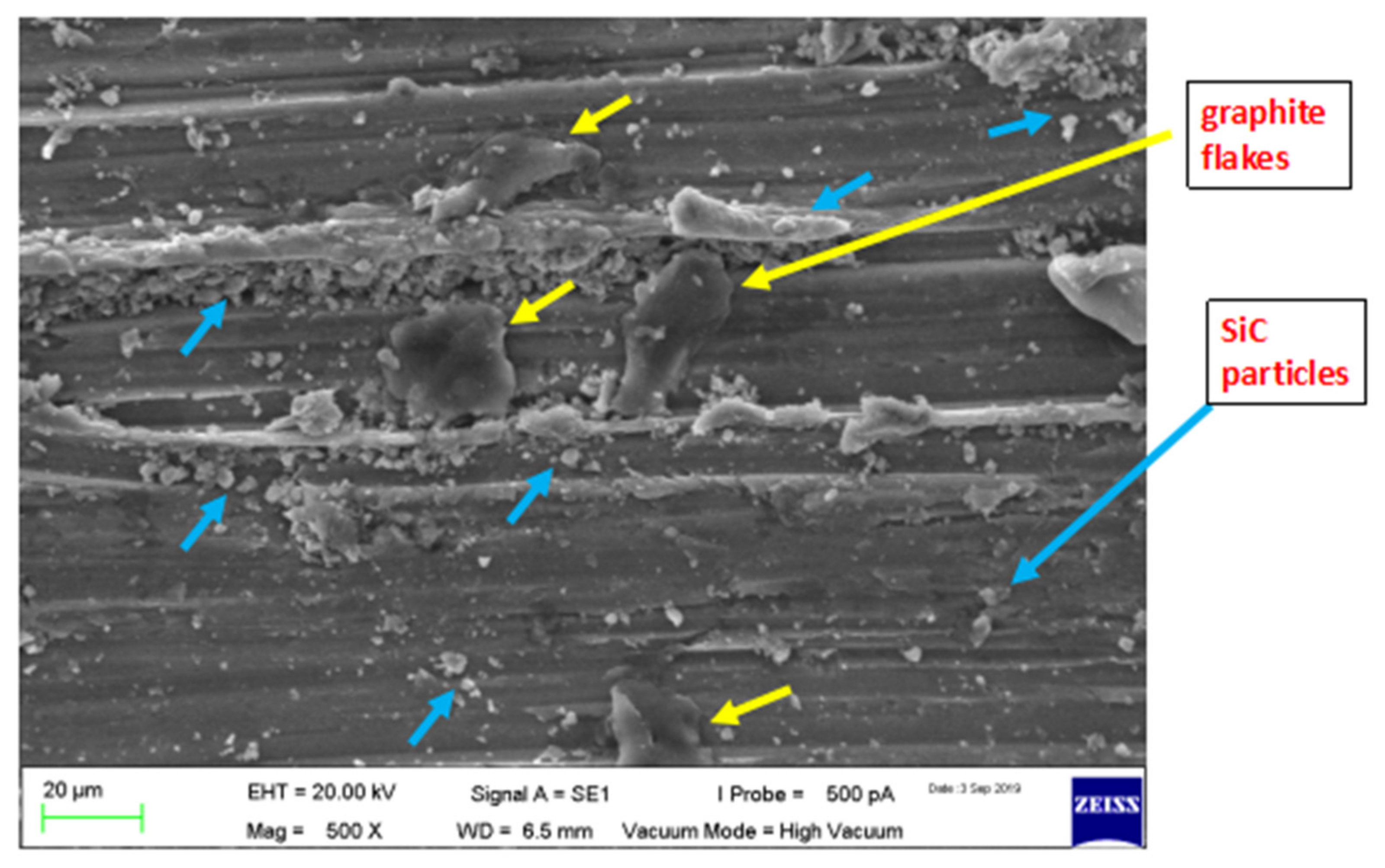
Figure 17. The dark black colored flakes of graphite have covered the large surface area on the wear tracks. These spread graphite layers act as a solid lubricating medium that subsequently reduces the mating surfaces’ wear rate.
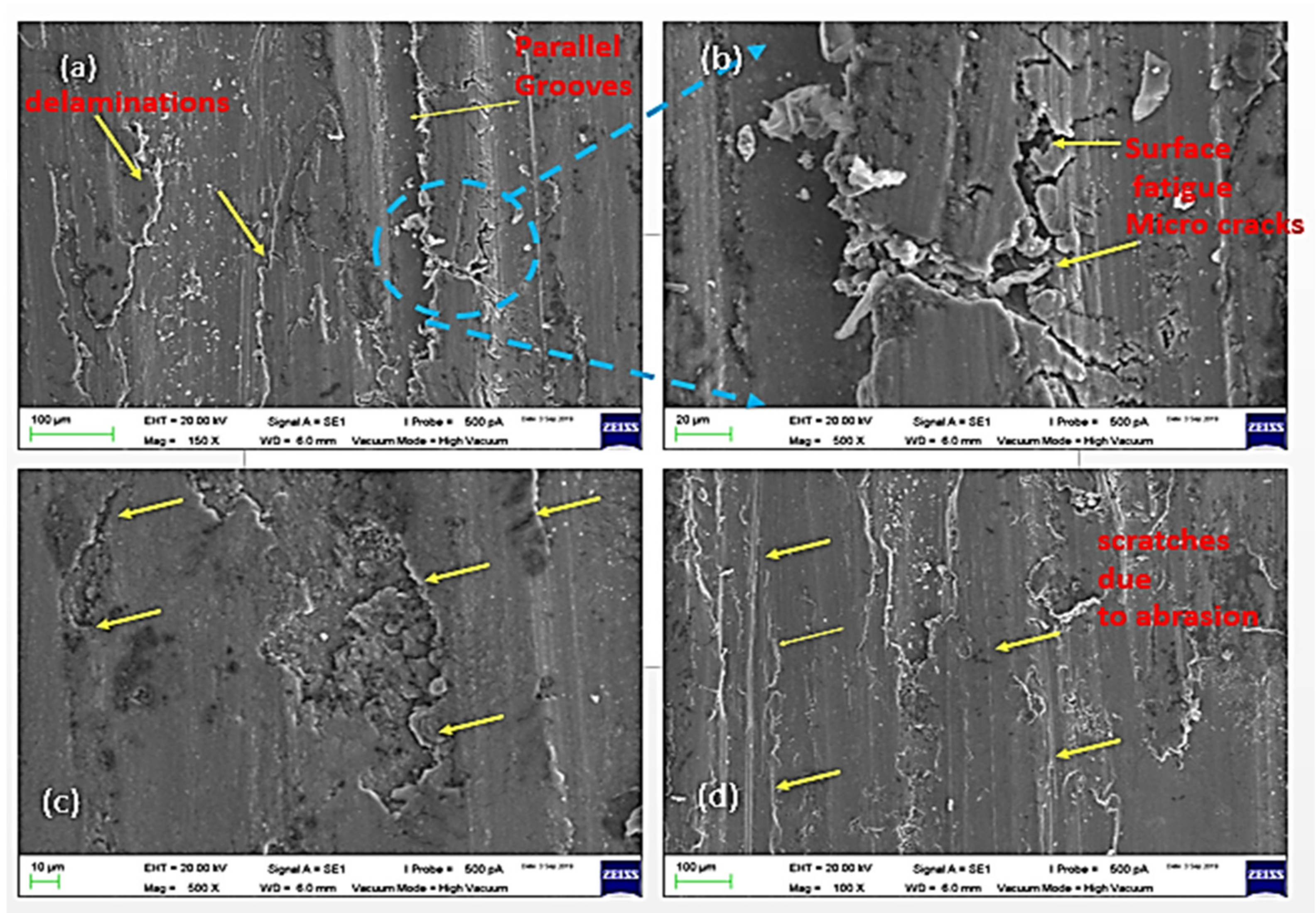
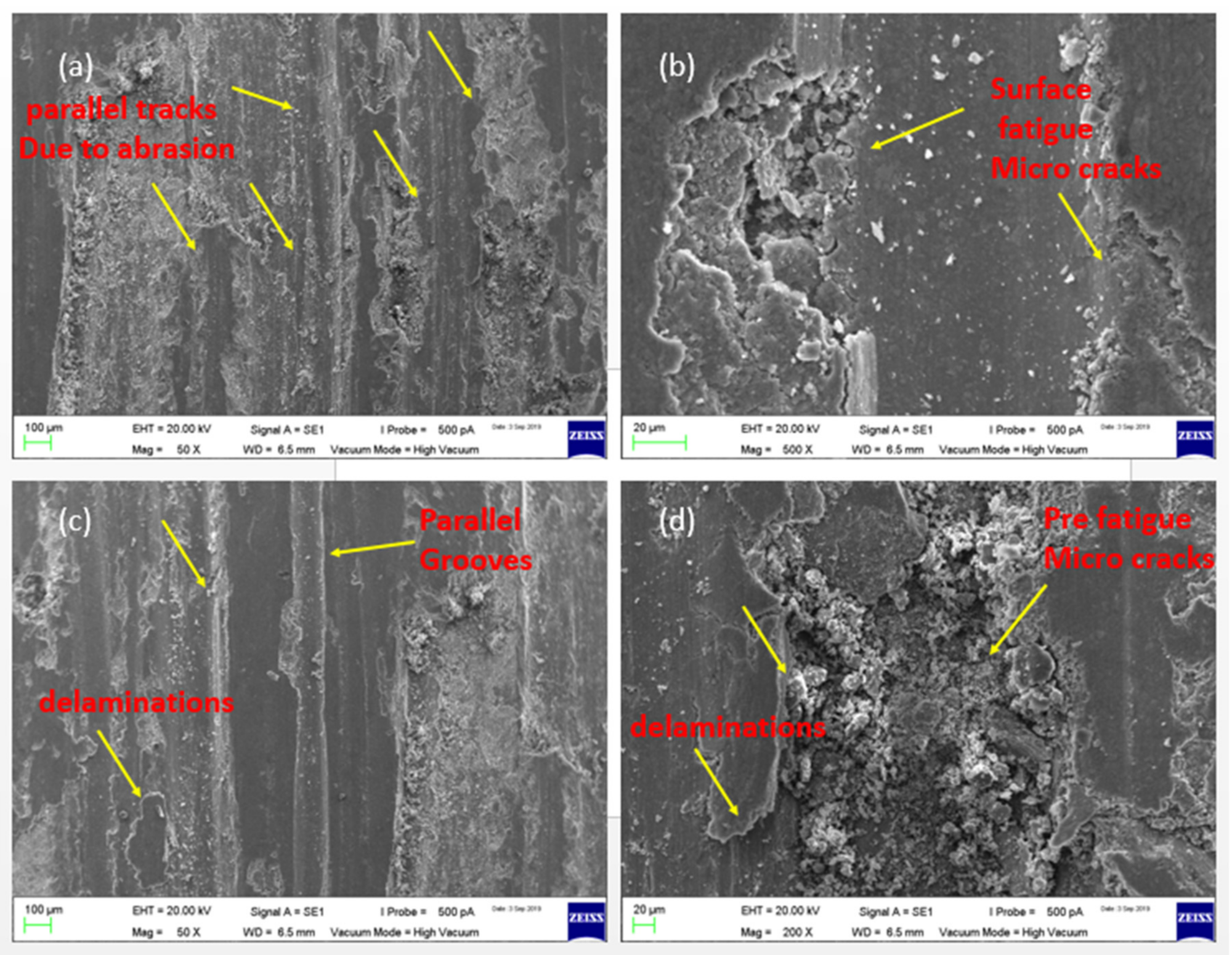
The surface composites with a high-volume percentage of reinforcements exhibit pulling out phenomenon as a result of low interfacial bonding with the base alloy. As seen in
Figure 18, the S-24 wear track exhibits such particles pulling out as a consequence of powder agglomeration and a lack of interfacial bonding with the base alloy, leading to a greater wear rate. Due to the existence of these hard reinforcing particles that have been torn out, the wear process has altered from adhesion to abrasion. The surface fatigue tendency has been increased and the micron sized craters have been observed due to particles pull out as shown in
Figure 18b. The pre-fatigue conditions bulging is observed as shown in
Figure 18d. The parallel grooves due to abrasion and delaminated layers are also observed on the surface as shown in
Figure 18c. So the surface wear has turned higher with abrasion, fatigue and delamination prone zones on this heavily reinforced, loosely particles bonded composite S-24. On other side, in case of the S-10 composite sample, the graphitized-SiC reinforcements resist wear prior to reaching high microhardness and form lubricative tribofilm owing to graphitic flakes between mating surfaces due to homogeneous distribution and strong interfacial bonding with the base alloy. As a result, the S-10 composite sample had a lower wear rate than the S-24 composite sample.
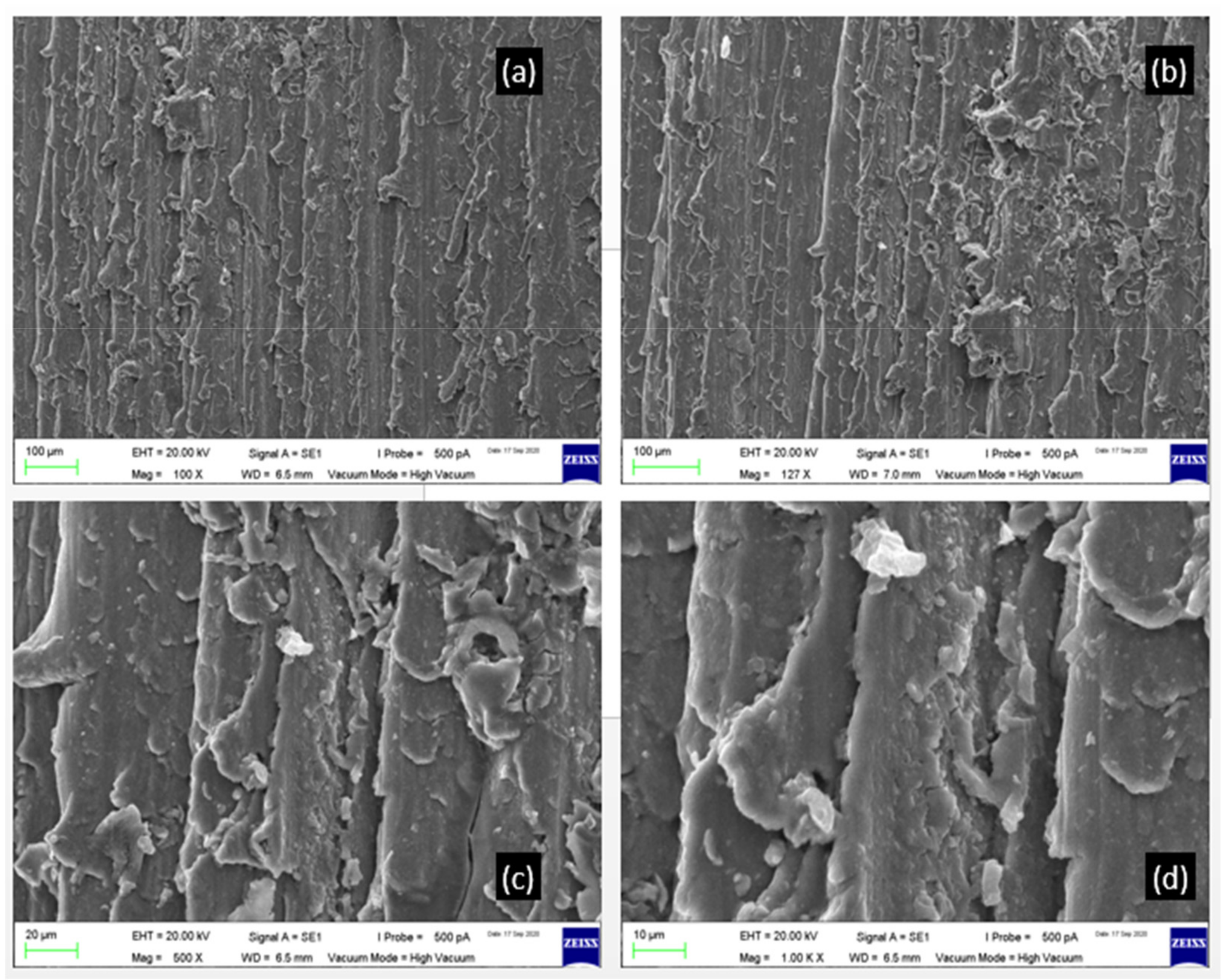
The experimental validation test, i.e., confirmation test sample, processed with parameters of tool rotation-1250 rpm, tool traverse-40 mm/min, hybrid ratio-90:10 and vol. percent.-12 have been tested for wear analysis. The wear tracks have been observed as shown in
Figure 19 and were also analyzed through EDX and mapping. The elemental analysis results are shown in
Figure 20. In this sample, the abrasive wear tracks are clearly visible with some delamination sites. The adhesive wear look thoroughly absent. The fatigue and fretting wear indications are also not present as shown in
Figure 19a–d micrographs. Thus, it can be concluded that the encapsulation of graphitized SiC reinforcement has successfully overcome the fretting fatigue behavior. The SiC particles have acted as the load-bearing elements. They are supported with the graphite tribolayers, making the surface-to-surface contact smooth, thus avoiding any further exploitations of the dendritic α-phase base aluminum alloy. The SiC particles and graphite flakes entrapped can be observed over the surface of wear tracks.
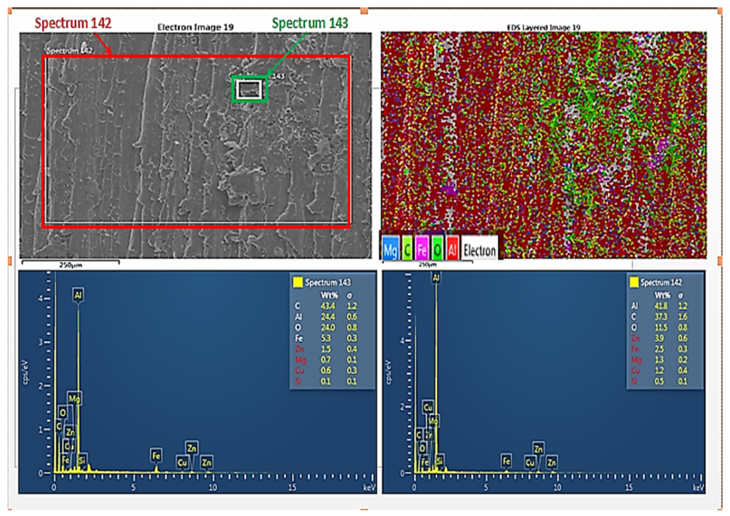
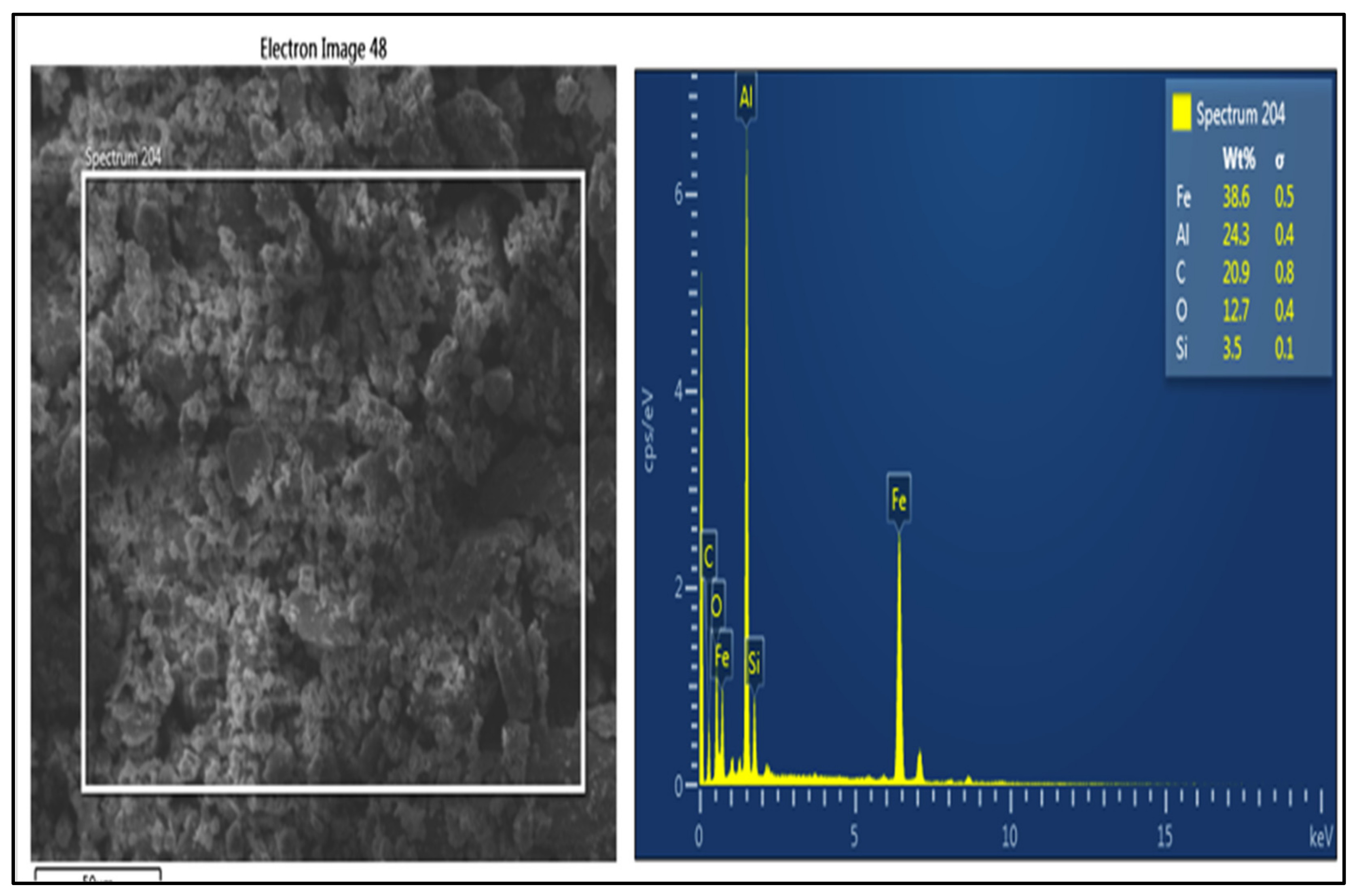
The wear tracks elemental analysis indicates that the wear track is filled with SiC/graphite reinforcement particles, ferrous disk debris particulates, and certain oxides formed with the alloying elements, mainly Zn oxides. The EDX table shows that carbon C- 37 wt% and oxygen O- 11 wt% are present over the surface next to the parent metal Al- 41 wt% for the spectrum 142. The small window that focuses on the dark particulates regions indicates that graphite-exfoliated nanolayers spread along with the oxides formed. The carbon C-43.4% and oxygen O-24% and the parent metal α-phase aluminum Al-24 wt% are detected in spectrum 143. This indicates that the graphite layers along with the SiC nanoparticles have well-encapsulated insides, have spread over the surface, and have been trapped between wear tracks to act as mechanically mixed layers. These tribolayers are responsible for the resultant change in the wear rate of the composite sample. The Al-Fe-O and ZnO formation over the surface is a common phenomenon during wear. The ZnO also is observed in the XRD analysis of the microstructure. The main alloying elements in the form of precipitates gets reacted with atmospheric oxygen during increased temperature environments dry sliding repetitive actions. The oxide films also indicate that the hard isomorphous precipitates have resisted the exploitation of base alloy dendritic structure during wear actions.
3.2.2. Wear Debris Analysis of AA7075-SiC/Graphite Composites
The wear debris of AA7075-T6, S-10, and S-24 AA7075-SiC/Gr Composite samples are analyzed using SEM imaging EDX and mapping elemental analysis. The wear debris images of base alloy AA7075-T6 are shown in
Figure 21. Their EDX and mapping results are displayed in
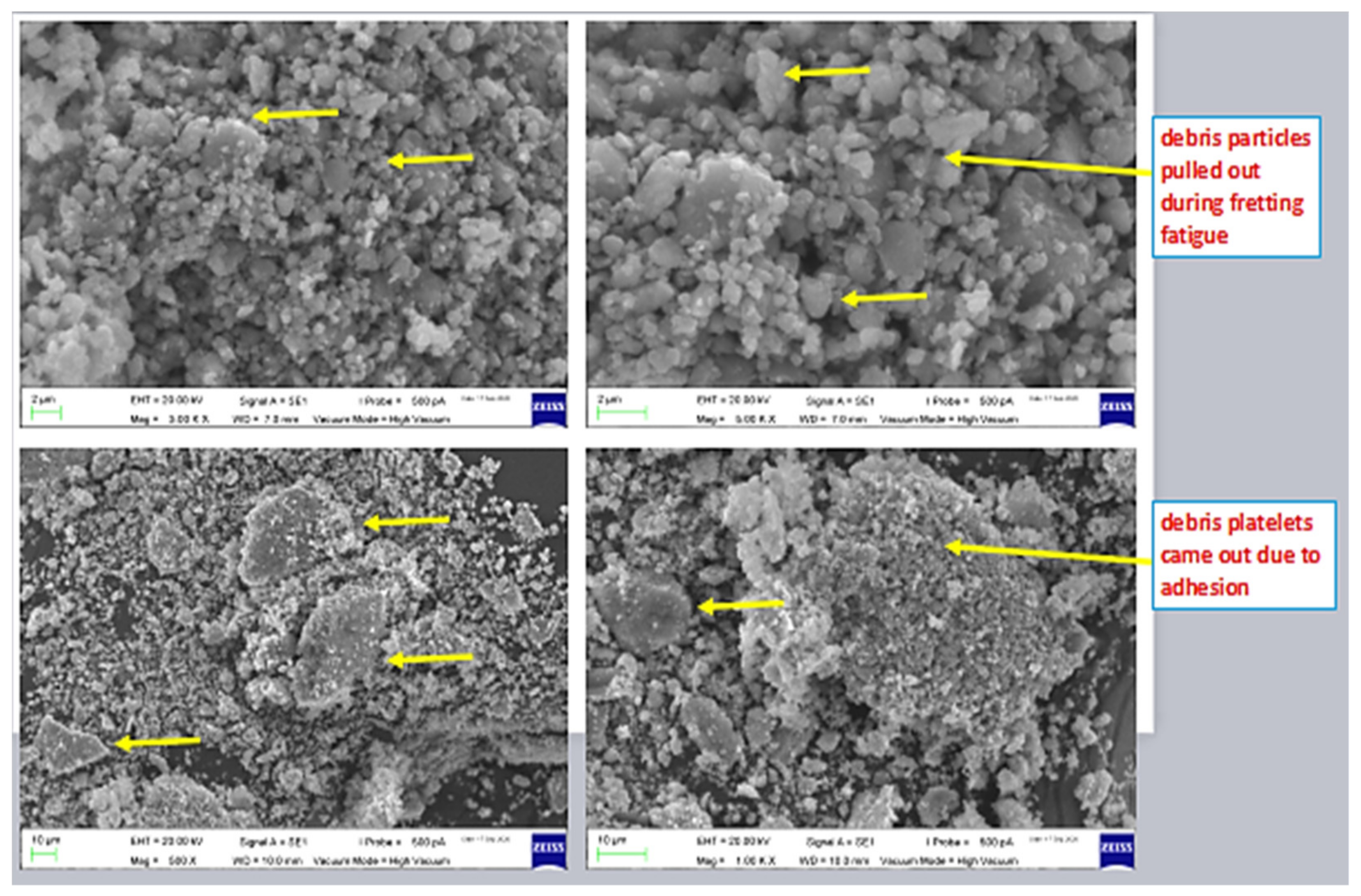
Figure 22. From the wear debris images, it is observed that there are mainly two shapes of particulates; one is fine spherical morphology particles which came out of the parent metal alloy during dry sliding wear because of fretting fatigue behavior. The surface cracking and nucleation around the hard precipitates result from the fretting fatigue repetitive loadings during dry sliding actions. Once the surface crack propagates, the inherent precipitates along with α-phase dendritic structures break down due to exposure to the surface repetitive loadings. These forms the fine particulate-shaped debris.
Secondly, the platelet-like debris are also observed in the imaging; platelets are mainly formed due to detachment during adhesion between the mating surfaces. With the increased temperature at the interface of mating asperities, the plastic flow takes place, which resembles the formation of platelet-like debris and the craters on the base alloy surface once these platelets detach entirely from the surface.
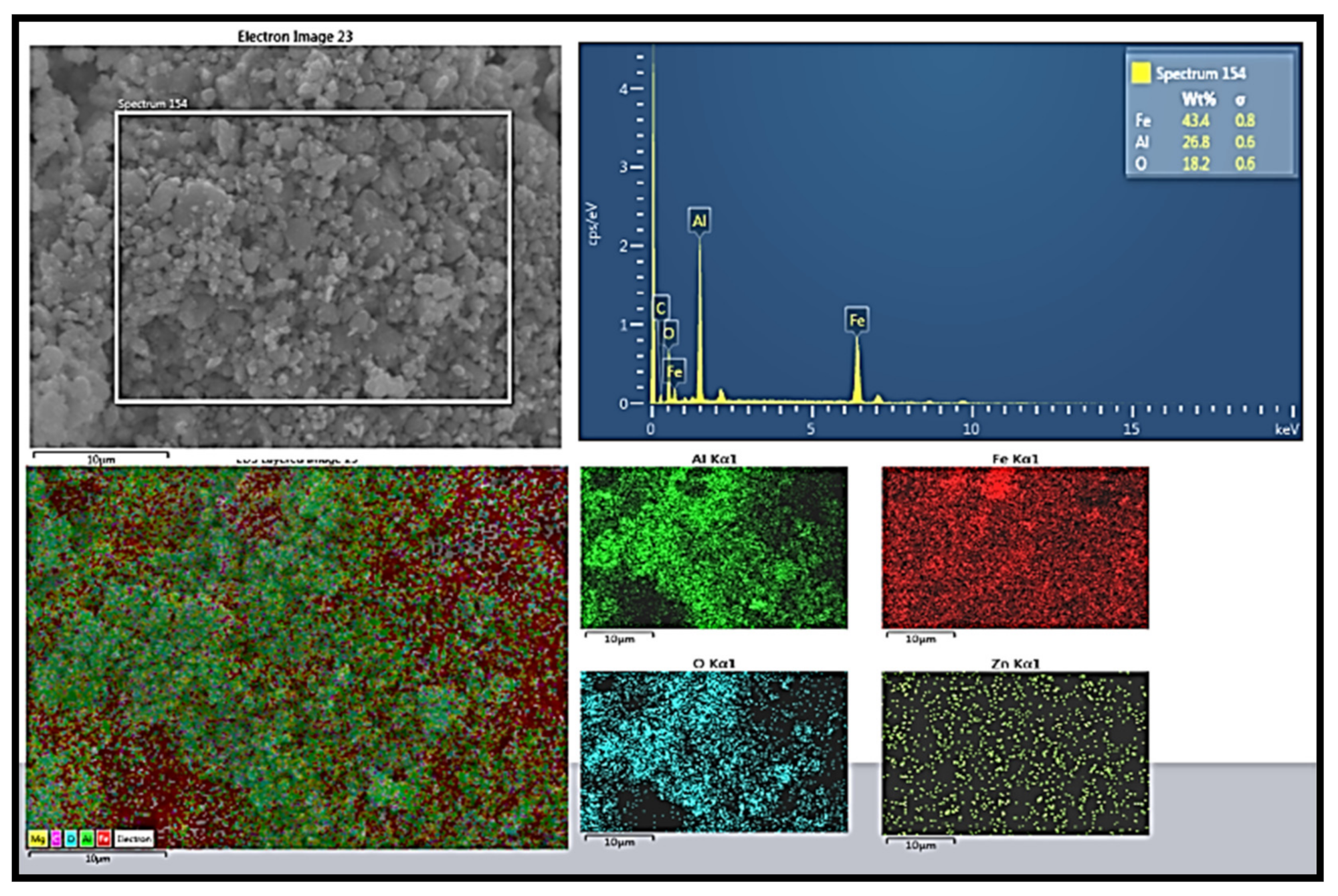
In the EDX and mapping analysis, the debris particles are observed to the mixture of (Al-Fe-O) oxides. The base aluminum alloy, the ferrous metal alloy disc, and the primary alloying element in the base alloy Zn react with the environmental oxygen to generate these oxides over the surface during the dry sliding actions. The Fe content of 47%, Al content of 27%, and O content of 15% are confirmed in the elemental analysis. The higher Fe content indicates that the hard inherent constituent phases have acted as resisting elements in the wear actions.
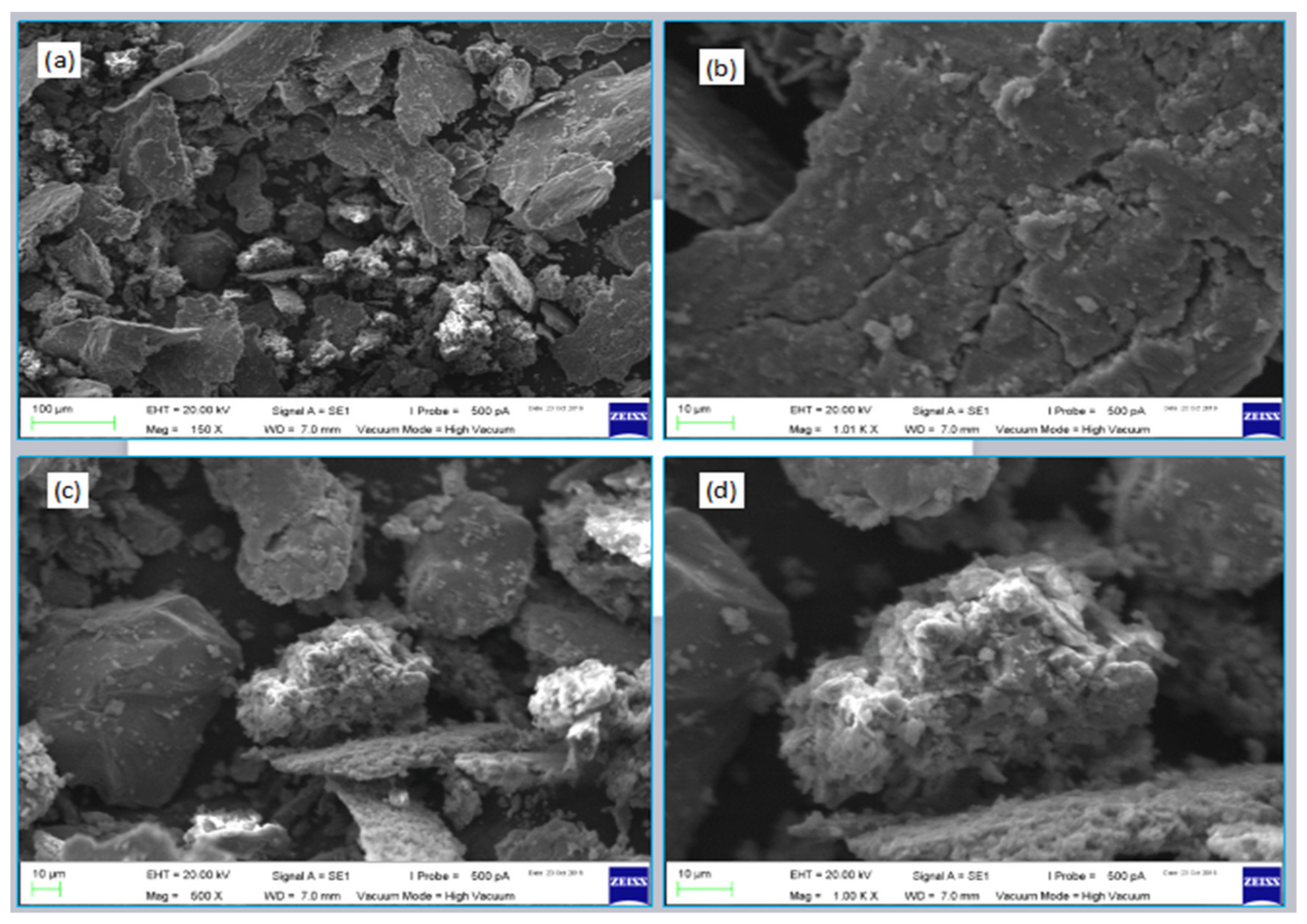
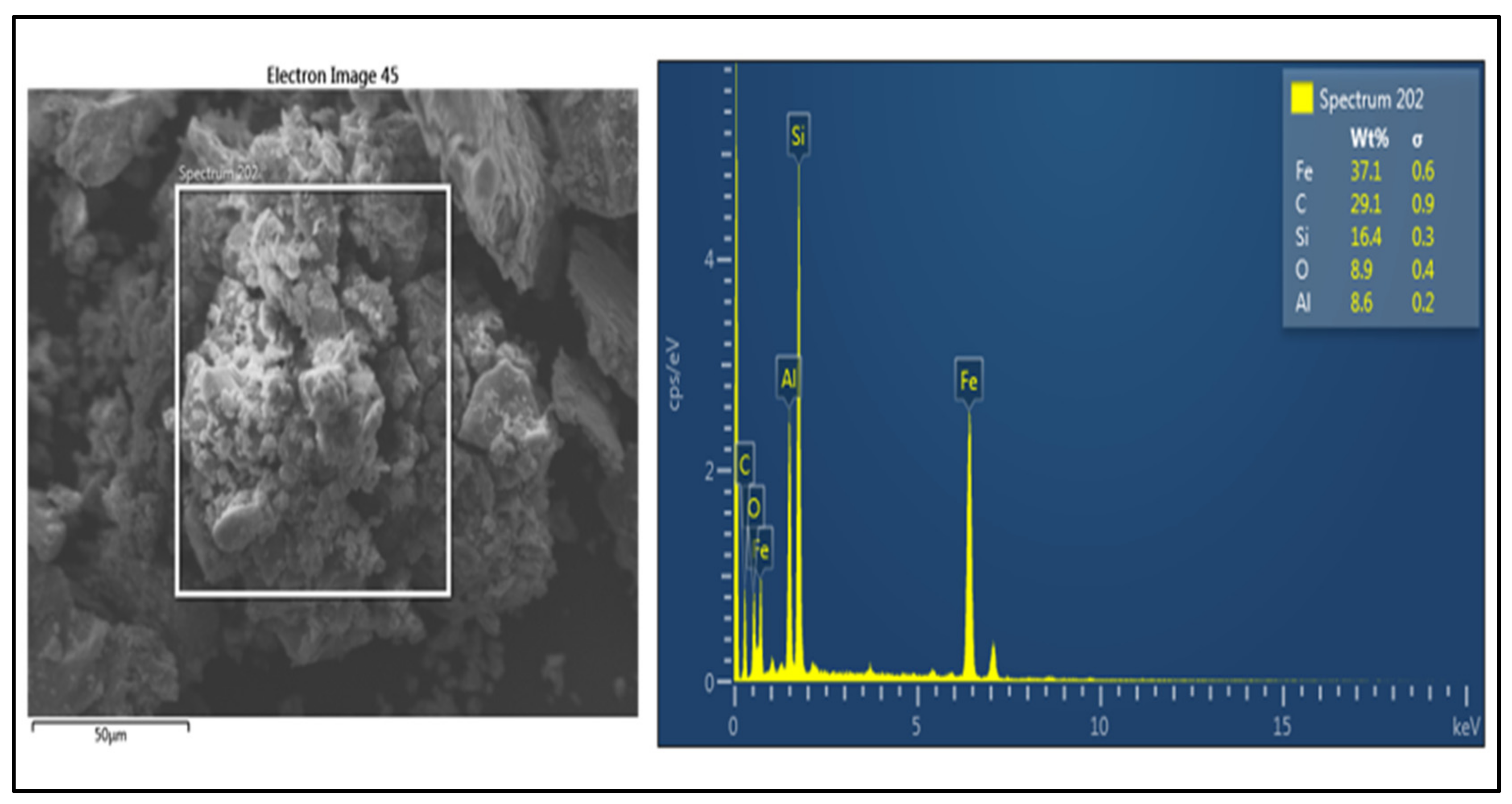
The wear debris of the S-24 sample for which the wear rate was the maximum has been analyzed, and the SEM images are shown in
Figure 23, and EDX mapping analysis is shown in
Figure 24 and
Figure 25. The wear debris show two types of morphologies, mainly the platelets and the spheroids of particulates. As shown in
Figure 23a,b the platelets are formed due to the initial fatigue, and then subsequent delamination wear mechanisms. The chip-like structures are pulled out once the cracks are entirely looped around delaminate. The second spheroids of particulates shown in
Figure 23c,d are formed due to small fine debris particles from both the pin and disc samples during fatigue continuation. The fine particles, during abrasive wear out actions, agglomerate together and form the spheroid-like structures. The spheroid structures indicate that once the initial asperities have dug out each other’s surface in the form of platelets, then the big particles dig-out of platelets or chunks is stopped. Subsequently, only fine debris particles have been observed in the next course of abrasive action because of the high quantity of SiC/Gr agglomeration zones with loose interfaces with the matrix. These fine particles roll between the surfaces and escape out of the zone as the optimized asperities now take full loads between them. The spheroids are formed since the nano-sized SiC/Gr particles tend to agglomerate because of their large surface areas.
The SEM EDX analysis shows that the higher Fe content is observed to be 37%, the carbon C-29%, silicon Si- 16.4%, and a small amount of Al-8%. Here, the critical point is that a higher content of SiC and graphite particles have been pulled out during abrasion due to the reinforcement’s high-volume percentage. Thus, these reinforcements have initially resisted the wear of the pin. Still, when the repetitive loading continued, the loose interfaces led to the particles pull-out instead of optimizing the firm shaped load-bearing asperities. The initial platelets were generated during the resistance to the mating surface asperities. Then, continuous fine particulates from the pin have been dug out as interfacial bonding was not good. Thus, it is indicated that reinforcement’s uniform dispersion with suitable interfaces with matrix material is an essential requirement irrespective of the nature of the reinforcement to be utilized. The latter can be functionalized if the dispersion and interfaces with the α-phase aluminum matrix are good.
The findings of the S-10 wear sample debris analysis are represented in
Figure 26,
Figure 27 and
Figure 28. The images of the wear debris generally depict small-sized particulates morphology and in combination with a few giant platelets. Here, in this case, the Fe content has increased in comparison to the last sample, i.e., 38.9%. The Al content is greater, and the Si and C percentages have significantly decreased. This indicates that the SiC and graphite particle pullout has not happened. Instead, the well-bonded graphitized SiC particles have acted as the load-bearing elements and have reduced the wear rate. The initial fatigue action has led to few platelet formations due to the combination of fatigue and delamination. However afterward, once the well-bonded graphitized-SiC particles have exposed and optimized their shapes as the active asperities, the wear rate has decreased significantly. The mechanically mixed layers of graphitized-SiC formed have continuously protected the pin sample area, and only fine debris particles due to abrasion are out. Thus, the large spheroids are not obtained; instead, the fine debris with small sizes is observed.


