
Influence of the Computer-Aided Static Navigation Technique and Mixed Reality Technology on the Accuracy of the Orthodontic Micro-Screws Placement. An In Vitro Study

Abstract
:1. Introduction
2. Materials and Methods
2.1. Study Design
2.2. Experimental Procedure
2.3. Measurement Procedure
2.4. Statistical Tests
3. Results
4. Discussion
5. Conclusions
Author Contributions
Funding
Institutional Review Board Statement
Informed Consent Statement
Data Availability Statement
Acknowledgments
Conflicts of Interest
References
- Papadopoulos, M.A.; Papageorgiou, S.N.; Zogakis, I.P. Clinical effectiveness of orthodontic miniscrew implants: A meta-analysis. J. Dent. Res. 2011, 90, 969–976. [Google Scholar] [CrossRef]
- Chen, Y.; Lee, J.W.; Cho, W.H.; Kyung, H.M. Potential of self-drilling orthodontic microimplants under immediate loading. Am. J. Orthod. Dentofac. Orthop. 2010, 137, 496–502. [Google Scholar] [CrossRef]
- Papadopoulos, M.A.; Tarawneh, F. The use of miniscrew implants for temporary skeletal anchorage in orthodontics: A comprehensive review. Oral Surg. Oral Med. Oral Pathol. Oral Radiol. Endod. 2007, 103, e6–e15. [Google Scholar] [CrossRef] [PubMed]
- Casaña-Ruiz, M.D.; Bellot-Arcís, C.; Paredes-Gallardo, V.; García-Sanz, V.; Almerich-Silla, J.M.; Montiel-Company, J.M. Risk factors for orthodontic mini-implants in skeletal anchorage biological stability: A systematic literature review and meta-analysis. Sci. Rep. 2020, 10, 1–10. [Google Scholar] [CrossRef] [PubMed] [Green Version]
- Bufalá, P.M.; O’Connor, E.M.; Zubizarreta-Macho, Á.; Riad Deglow, E.; Hernández Montero, S.; Abella Sans, F.; Albaladejo Martínez, A. Novel Digital Technique to Analyze the Influence of the Operator Experience on the Accuracy of the Orthodontic Micro-Screws Placement. Appl. Sci. 2021, 11, 400. [Google Scholar] [CrossRef]
- Pithon, M.M.; Figueiredo, D.S.F.; Oliveira, D. Mechanical Evaluation of Orthodontic Mini-Implants of Different Lengths. J. Oral Maxillofac. Surg. 2013, 71, 479–486. [Google Scholar] [CrossRef]
- Qamruddin, I.; Nazir, M. Shahid F Factors that contribute to the failure of orthodontic mini-implants: A literature review. Pak. Orthod. J. 2010, 2, 76–81. [Google Scholar]
- Motoyoshi, M.; Yoshida, T.; Ono, A.; Shimizu, N. Effect of cortical bone thickness and implant placement torque on stability of orthodontic mini-implants. Int. J. Oral Maxillofac. Implant. 2007, 22, 779–784. [Google Scholar]
- Ono, A.; Motoyoshi, M.; Shimizu, N. Cortical bone thickness in the buccal posterior region for orthodontic mini-implants. Int. J. Oral Maxillofac. Surg. 2008, 37, 334–340. [Google Scholar] [CrossRef]
- Consolaro, A.; Romano, F.L. Reasons for mini-implants failure: Choosing installation site should be valued. Dental Press J. Orthod. 2014, 19, 18–24. [Google Scholar] [CrossRef] [Green Version]
- Jung, Y.R.; Kim, S.C.; Kang, K.H.; Cho, J.H.; Lee, E.H.; Chang, N.Y.; Chae, J.M. Placement angle effects on the success rate of orthodontic microimplants and other factors with cone-beam computed tomography. Am. J. Orthod. Dentofac. Orthop. 2013, 143, 173–181. [Google Scholar] [CrossRef] [PubMed]
- Kuroda, S.; Yamada, K.; Deguchi, T.; Hashimoto, T.; Kyung, H.-M.; Yamamoto, T.T. Root proximity is a major factor for screw failure in orthodontic anchorage. Am. J. Orthod. Dentofac. Orthop. 2007, 131, S68–S73. [Google Scholar] [CrossRef] [PubMed]
- Santiago, R.C.; De Paula, F.O.; Fraga, M.R.; Assis, N.M.S.P.; Vitral, R.W.F. Correlation between miniscrew stability and bone mineral density in orthodontic patients. Am. J. Orthod. Dentofac. Orthop. 2009, 136, 243–250. [Google Scholar] [CrossRef]
- Daokar, S.; Gauri, G.; Mahesh, L. Orthodontic implant failure: A systematic review. Int. J. Oral Implantol. Clin. Res. 2016, 7, 1–6. [Google Scholar] [CrossRef]
- Kyung, H.-M.; Park, H.-S.; Bae, S.-M.; Sung, J.-H.; Kim, I.-B. Development of orthodontic micro-implants for intraoral anchorage. J. Clin. Orthod. 2003, 37, 321–328. [Google Scholar] [PubMed]
- Park, J.H.; Chae, J.-M.; Bay, R.C.; Kim, M.-J.; Lee, K.-Y.; Chang, N.-Y. Evaluation of factors influencing the success rate of orthodontic microimplants using panoramic radiographs. Korean J. Orthod. 2018, 48, 30–38. [Google Scholar] [CrossRef] [PubMed] [Green Version]
- Proffit, W.R. Contemporary Orthodontics, 6th ed.; Elsevier Health Sciences: Amsterdam, The Netherlands, 2018. [Google Scholar]
- Kadioglu, O.; Büyükyilmaz, T.; Zachrisson, B.U.; Maino, B.G. Contact damage to root surfaces of premolars touching miniscrews during orthodontic treatment. Am. J. Orthod. Dentofac. Orthop. 2008, 134, 353–360. [Google Scholar] [CrossRef]
- Park, H.S. The usage of microimplants in orthodontics. In Current Therapy in Orthodontics; Nanda, R., Kapila, S., Eds.; Mosby Inc.: Maryland Heights, MO, USA, 2010; pp. 291–300. [Google Scholar]
- Papageorgiou, S.N.; Zogakis, I.P.; Papadopoulos, M. Failure rates and associated risk factors of orthodontic miniscrew implants: A meta-analysis. Am. J. Orthod. Dentofac. Orthop. 2012, 142, 577–595.e7. [Google Scholar] [CrossRef]
- Kalra, S.; Tripathi, T.; Rai, P.; Kanase, A. Evaluation of orthodontic mini-implant placement: A CBCT study. Prog. Orthod. 2014, 15, 61. [Google Scholar] [CrossRef] [Green Version]
- Suzuki, E.Y.; Suzuki, B. Accuracy of Miniscrew Implant Placement with a 3-Dimensional Surgical Guide. J. Oral Maxillofac. Surg. 2008, 66, 1245–1252. [Google Scholar] [CrossRef]
- Durham, M.; Engel, B.; Ferrill, T.; Halford, J.; Singh, T.P.; Gladwell, M. Digitally Augmented Learning in Implant Dentistry. Oral Maxillofac. Surg. Clin. N. Am. 2019, 31, 387–398. [Google Scholar] [CrossRef]
- Elbashti, M.E.; Itamiya, T.; Aswehlee, A.M.; I Sumita, Y.; Ella, B.; Naveau, A. Augmented Reality for Interactive Visualization of 3D Maxillofacial Prosthetic Data. Int. J. Prosthodont. 2020, 33, 680–683. [Google Scholar] [CrossRef] [PubMed]
- Cozzani, M.; Nucci, L.; Lupini, D.; Dolatshahizand, H.; Fazeli, D.; Barzkar, E.; Naeini, E.; Jamilian, A. The ideal insertion angle after immediate loading in Jeil, Storm, and Thunder miniscrews: A 3D-FEM study. Int. Orthod. 2020, 18, 503–508. [Google Scholar] [CrossRef] [PubMed]
- 2Liu, H.; Liu, D.-X.; Wang, G.; Wang, C.-L.; Zhao, Z. Accuracy of surgical positioning of orthodontic miniscrews with a computer-aided design and manufacturing template. Am. J. Orthod. Dentofac. Orthop. 2010, 137, 728.e1–728.e10. [Google Scholar] [CrossRef]
- Qiu, L.; Haruyama, N.; Suzuki, S.; Yamada, D.; Obayashi, N.; Kurabayashi, T.; Moriyama, K. Accuracy of orthodontic miniscrew implantation guided by stereolithographic surgical stent based on cone-beam CT-derived 3D images. Angle Orthod. 2012, 82, 284–293. [Google Scholar] [CrossRef] [Green Version]
- Bae, M.-J.; Kim, J.-Y.; Park, J.-T.; Cha, J.-Y.; Kim, H.-J.; Yu, H.-S.; Hwang, C.-J. Accuracy of miniscrew surgical guides assessed from cone-beam computed tomography and digital models. Am. J. Orthod. Dentofac. Orthop. 2013, 143, 893–901. [Google Scholar] [CrossRef] [PubMed]
- Miyazawa, K.; Kawaguchi, M.; Tabuchi, M.; Goto, S. Accurate pre-surgical determination for self-drilling miniscrew implant placement using surgical guides and cone-beam computed tomography. Eur. J. Orthod. 2010, 32, 735–740. [Google Scholar] [CrossRef] [PubMed] [Green Version]
- Cassetta, M.; Altieri, F.; Di Giorgio, R.; Barbato, E. Palatal orthodontic miniscrew insertion using a CAD-CAM surgical guide: Description of a technique. Int. J. Oral Maxillofac. Surg. 2018, 47, 1195–1198. [Google Scholar] [CrossRef]
- Qiu, L.L.; Li, S.; Bai, Y.X. [Preliminary safety and stability assessment of orthodontic miniscrew implantation guided by surgical template based on cone-beam CT images]. Zhonghua Kou Qiang Yi Xue Za Zhi = Zhonghua Kouqiang Yixue Zazhi = Chin. J. Stomatol. 2016, 51, 336–340. [Google Scholar]
- Almeida, M.R. Biomechanics of extra-alveolar mini-implants. Dent. Press J. Orthod. 2019, 24, 93–109. [Google Scholar] [CrossRef] [PubMed] [Green Version]
- Lee, Y.-K.; Kim, J.-W.; Baek, S.-H.; Kim, T.-W.; Chang, Y.-I. Root and Bone Response to the Proximity of a Mini-Implant under Orthodontic Loading. Angle Orthod. 2010, 80, 452–458. [Google Scholar] [CrossRef] [Green Version]
- Melsen, B.; Verna, C. Miniscrew implants: The Aarhus anchorage system. Semin. Orthod. 2005, 11, 24–31. [Google Scholar] [CrossRef]
- Asscherickx, K.; Vannet, B.V.; Wehrbein, H.; Sabzevar, M.M. Root repair after injury from mini-screw. Clin. Oral Implant. Res. 2005, 16, 575–578. [Google Scholar] [CrossRef] [PubMed]
- Suzuki, E.Y.; Buranastidporn, B. An adjustable surgical guide for miniscrew placement. J. Clin. Orthod. 2005, 39, 588–590. [Google Scholar]
- Kravitz, N.D.; Kusnoto, B. Risks and complications of orthodontic miniscrews. Am. J. Orthod. Dentofac. Orthop. 2007, 131, S43–S51. [Google Scholar] [CrossRef] [PubMed]
- Carano, A.; Velo, S.; Leone, P.; Siciliani, G. Clinical applications of the Miniscrew Anchorage System. J. Clin. Orthod. 2005, 39, 9–24. [Google Scholar] [PubMed]
- Morea, C.; Dominguez, G.C.; Wuo, A.D.V.; Tortamano, A. Surgical guide for optimal positioning of mini-implants. J. Clin. Orthod. 2005, 39, 317–321. [Google Scholar] [PubMed]
- Bae, S.-M.; Park, H.-S.; Kyung, H.-M.; Kwon, O.-W.; Sung, J.-H. Clinical application of micro-implant anchorage. J. Clin. Orthod. 2002, 36, 298–302. [Google Scholar] [PubMed]
- Dula, K.; Mini, R.; Van Der Stelt, P.F.; Buser, D. The radiographic assessment of implant patients: Decision-making criteria. Int. J. Oral Maxillofac. Implant. 2001, 16, 80–89. [Google Scholar]
- Hammarstrom, L.; Blomlof, L.; Lindskog, S. Dynamics of dentoalveolar ankylosis and associated root resorption. Dent. Traumatol. 1989, 5, 163–175. [Google Scholar] [CrossRef]
- Motoyoshi, M.; Uchida, Y.; Matsuoka, M.; Inaba, M.; Iwai, H.; Karasawa, Y.; Shimizu, N. Assessment of damping capacity as an index of root proximity in self-drilling orthodontic mini-implants. Clin. Oral Investig. 2014, 18, 321–326. [Google Scholar] [CrossRef] [PubMed]
- Gintautaitė, G.; Kenstavičius, G.; Gaidytė, A. Dental roots’ and surrounding structures’ response after contact with orthodontic mini implants: A systematic literature review. Stomatologija 2018, 20, 73–81. [Google Scholar] [PubMed]
- Ma, L.; Jiang, W.; Zhang, B.; Qu, X.; Ning, G.; Zhang, X.; Liao, H. Augmented reality surgical navigation with accurate CBCT-patient registration for dental implant placement. Med. Biol. Eng. Comput. 2018, 57, 47–57. [Google Scholar] [CrossRef] [PubMed]
- Jiang, W.; Ma, L.; Zhang, B.; Fan, Y.; Qu, X.; Zhang, X.; Liao, H. Evaluation of the 3D Augmented Reality–Guided Intraoperative Positioning of Dental Implants in Edentulous Mandibular Models. Int. J. Oral Maxillofac. Implant. 2018, 33, 1219–1228. [Google Scholar] [CrossRef]


| n | Mean | SD | Minimum | Maximum | ||
|---|---|---|---|---|---|---|
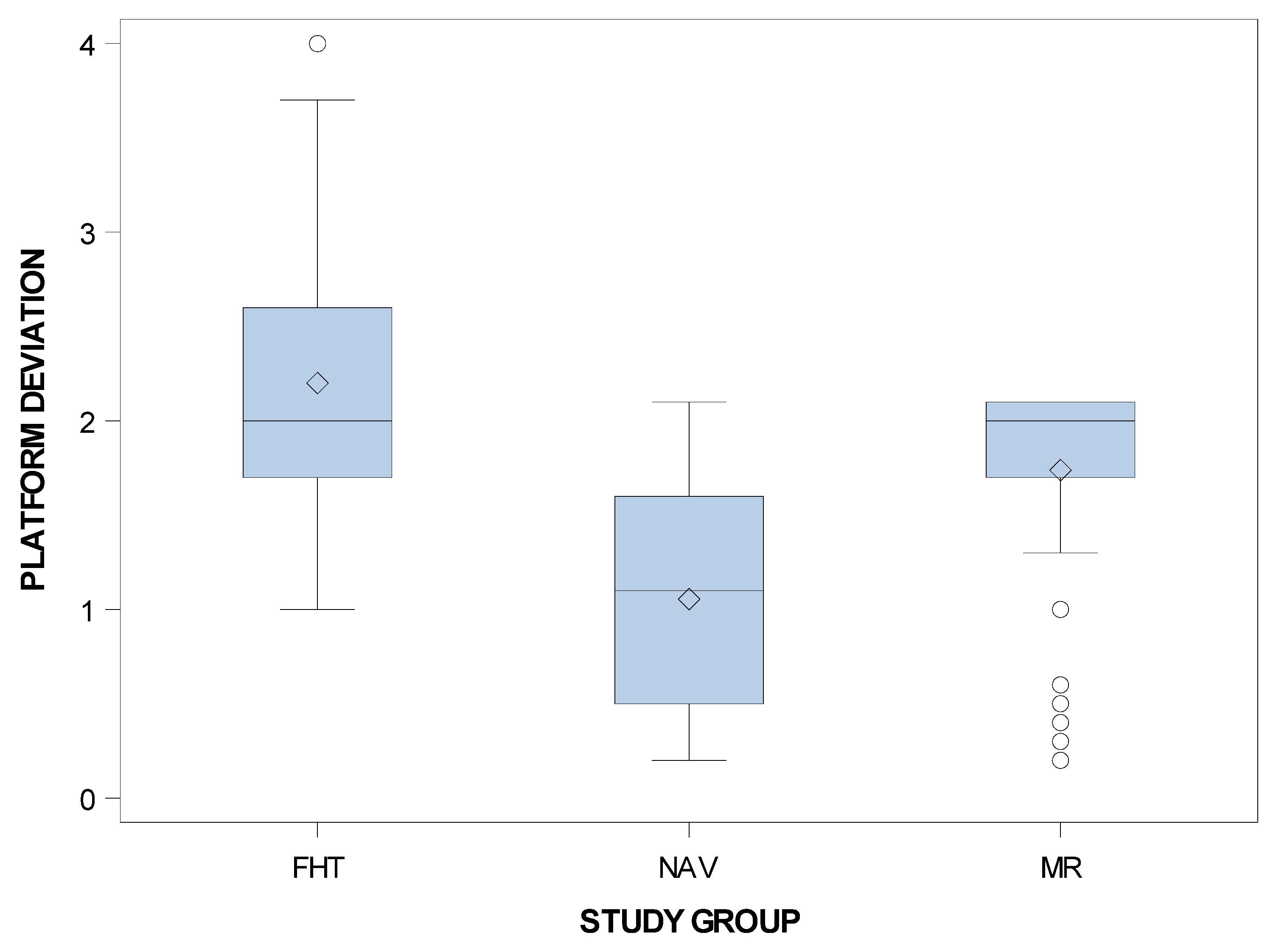
| Coronal | NAV | 69 | 1.06 | 0.59 | 0.20 | 2.10 |
| MR | 69 | 1.74 | 0.52 | 0.20 | 2.10 | |
| FHT | 69 | 2.20 | 2.00 | 1.00 | 4.00 | |
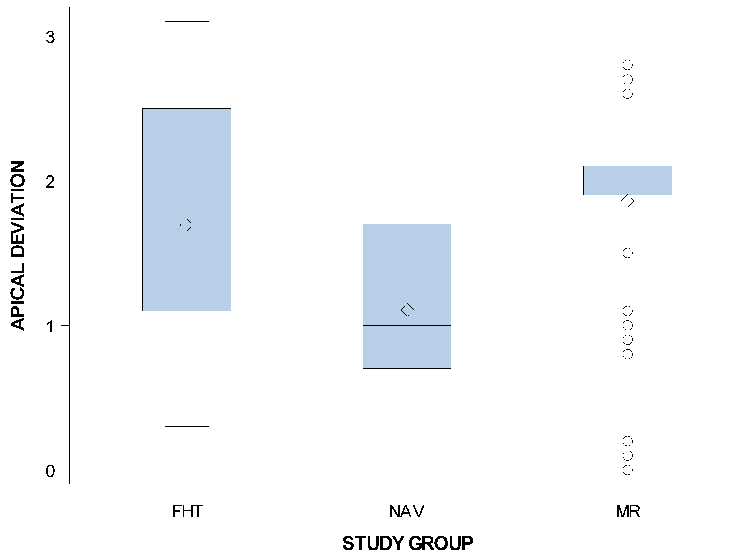
| Apical | NAV | 69 | 1.11 | 0.77 | 0.10 | 2.80 |
| MR | 69 | 1.86 | 0.65 | 0.00 | 2.80 | |
| FHT | 69 | 1.69 | 0.82 | 0.40 | 3.10 | |
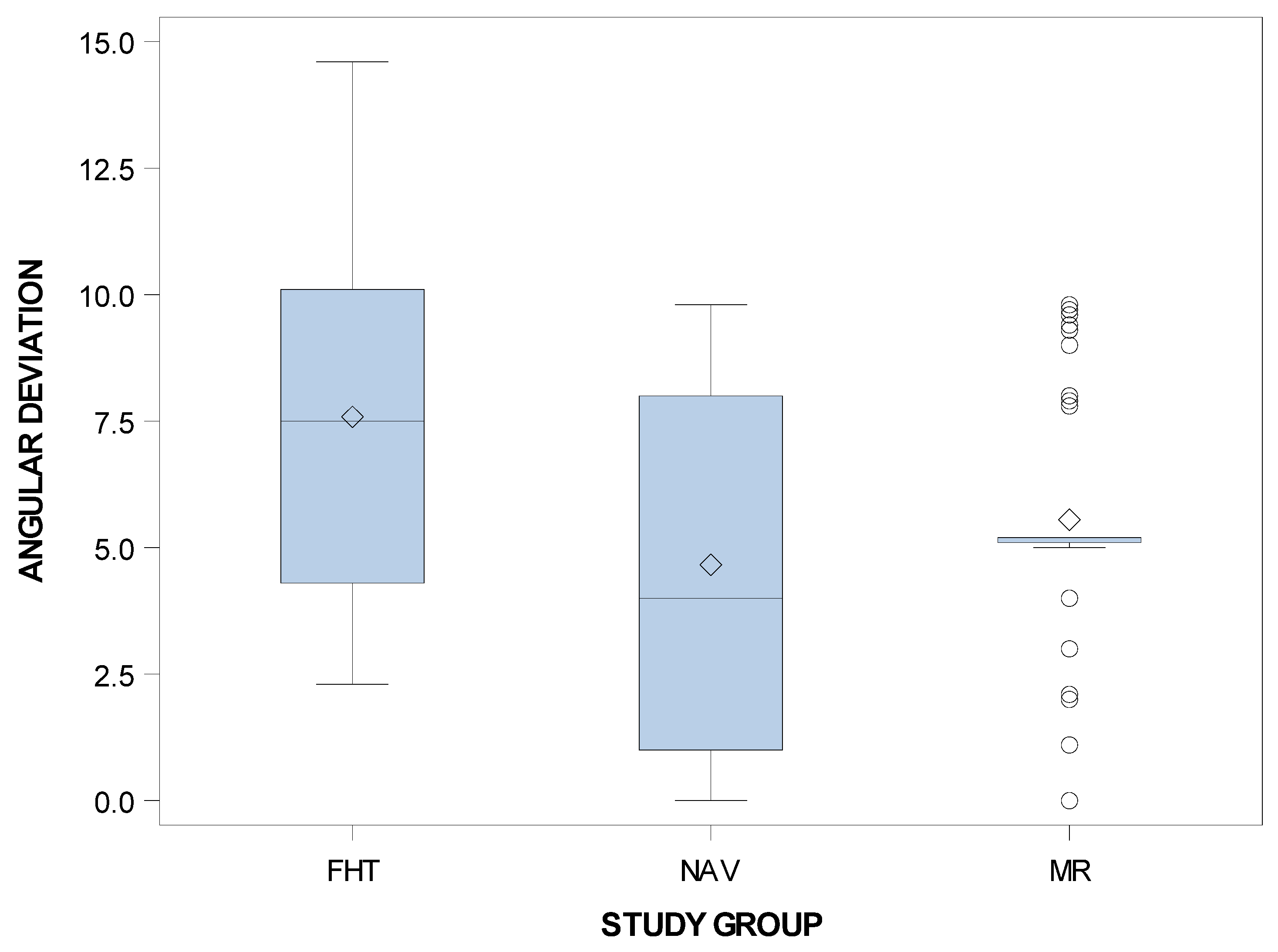
| Angular | NAV | 69 | 4.66 | 3.65 | 0.00 | 9.80 |
| MR | 69 | 5.55 | 2.46 | 0.00 | 9.80 | |
| FHT | 69 | 7.58 | 3.50 | 2.30 | 14.60 |
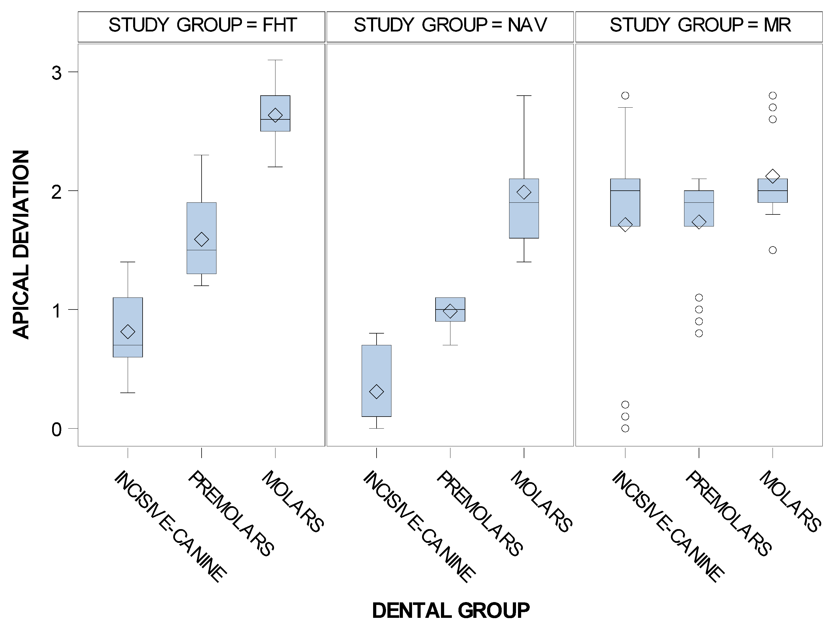
| n | Mean | SD | Minimum | Maximum | ||
|---|---|---|---|---|---|---|
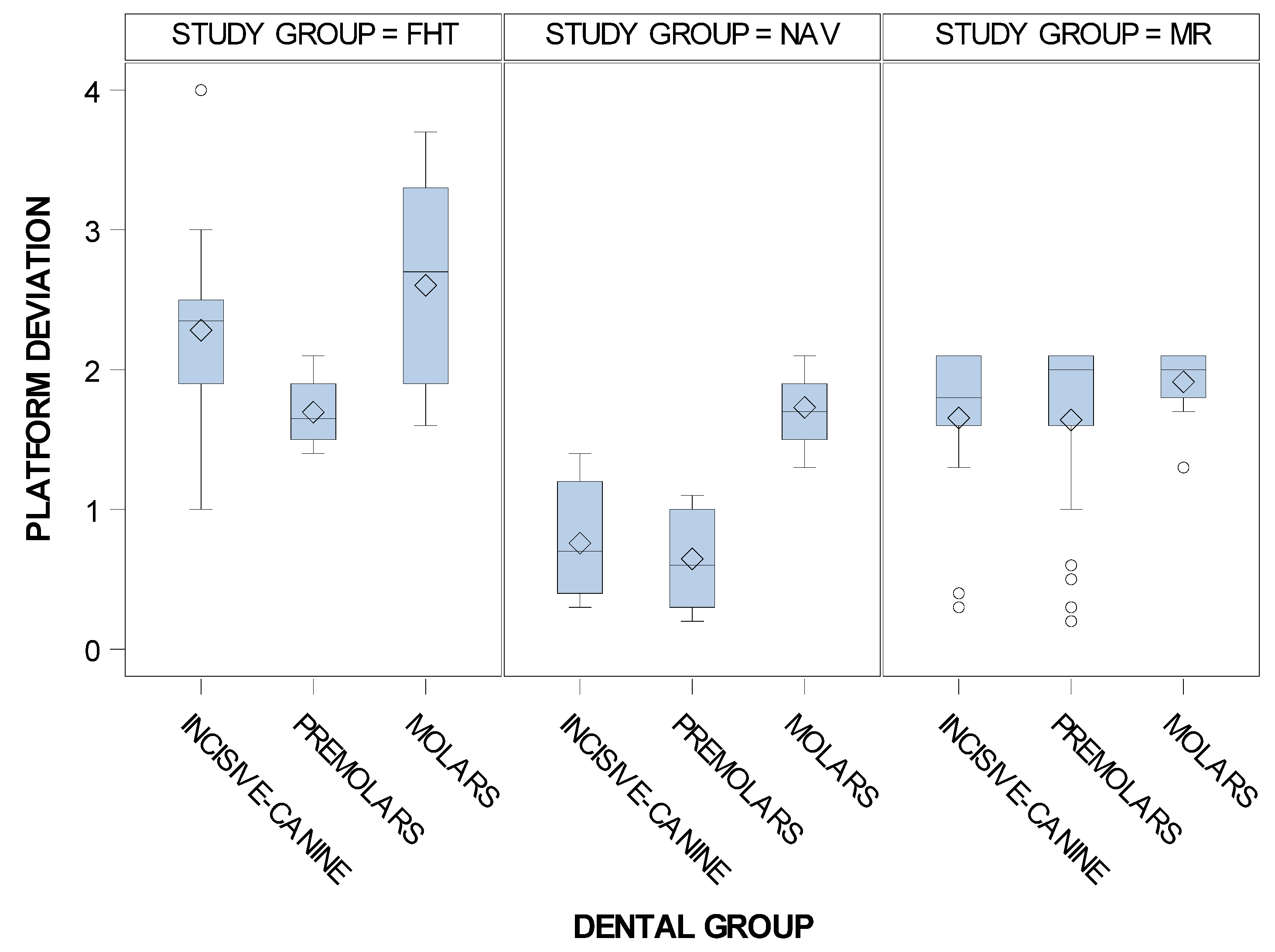
| Inci sive-canine | NAV | 23 | 0.76 | 0.39 | 0.30 | 1.40 |
| MR | 23 | 1.65 | 0.57 | 0.30 | 2.10 | |
| FHT | 23 | 2.28 | 0.63 | 1.00 | 4.00 | |
| Premolar | NAV | 23 | 0.65 | 0.35 | 0.20 | 1.10 |
| MR | 23 | 1.64 | 0.65 | 0.20 | 2.10 | |
| FHT | 23 | 1.70 | 0.25 | 1.40 | 2.10 | |
| Molar | NAV | 23 | 1.73 | 0.24 | 1.30 | 2.10 |
| MR | 23 | 1.91 | 0.20 | 1.30 | 2.10 | |
| FHT | 23 | 2.60 | 0.65 | 1.60 | 3.70 |
| n | Mean | SD | Minimum | Maximum | |
|---|---|---|---|---|---|
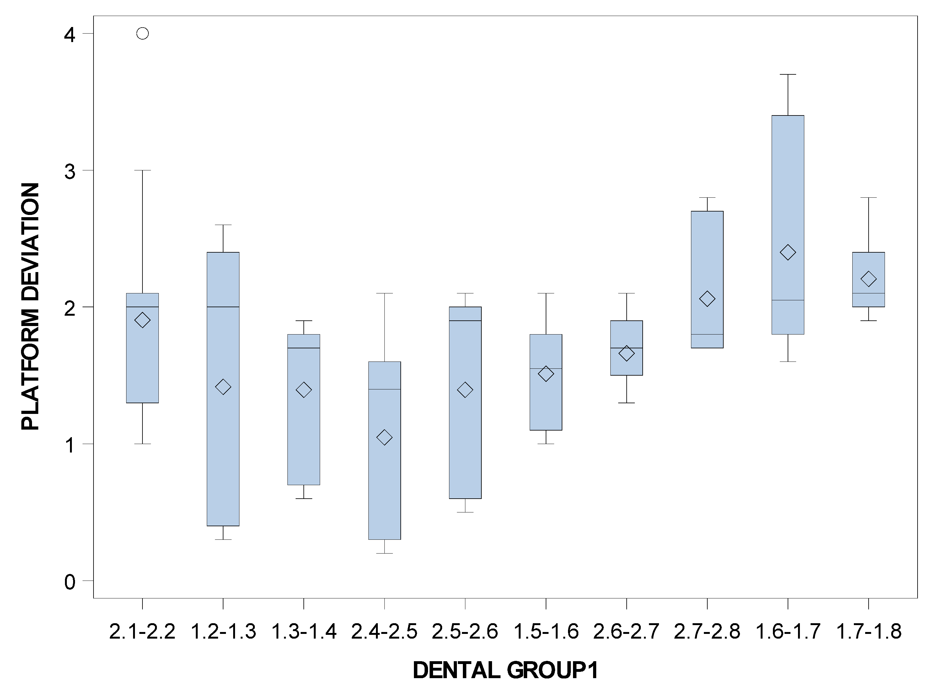
| 2.1–2.2 | 14 | 1.90 | 0.78 | 1.00 | 4.00 |
| 1.2–1.3 | 14 | 1.42 | 0.99 | 0.30 | 2.60 |
| 1.3–1.4 | 13 | 1.40 | 0.53 | 0.60 | 1.90 |
| 2.4–2.5 | 14 | 1.05 | 0.73 | 0.20 | 2.10 |
| 2.5–2.6 | 14 | 1.40 | 0.75 | 0.50 | 2.10 |
| 1.5–1.6 | 14 | 1.51 | 0.40 | 1.00 | 2.10 |
| 2.6–2.7 | 13 | 1.66 | 0.25 | 1.30 | 2.10 |
| 2.7–2.8 | 14 | 2.06 | 0.47 | 1.70 | 2.80 |
| 1.6–1.7 | 14 | 2.40 | 0.78 | 1.60 | 3.70 |
| 1.7–1.8 | 14 | 2.21 | 0.28 | 1.90 | 2.80 |
| n | Mean | SD | Minimum | Maximum | ||
|---|---|---|---|---|---|---|
| Inci sive-canine | NAV | 23 | 0.31 | 0.32 | 0.00 | 0.80 |
| MR | 23 | 1.71 | 0.95 | 0.00 | 2.80 | |
| FHT | 23 | 0.81 | 0.34 | 0.30 | 1.40 | |
| Premolar | NAV | 23 | 0.99 | 0.12 | 0.70 | 1.10 |
| MR | 23 | 1.74 | 0.46 | 0.80 | 2.10 | |
| FHT | 23 | 1.59 | 0.35 | 1.20 | 2.30 | |
| Molar | NAV | 23 | 1.99 | 0.43 | 1.40 | 2.80 |
| MR | 23 | 2.12 | 0.34 | 1.50 | 2.80 | |
| FHT | 23 | 2.63 | 0.25 | 2.20 | 3.10 |
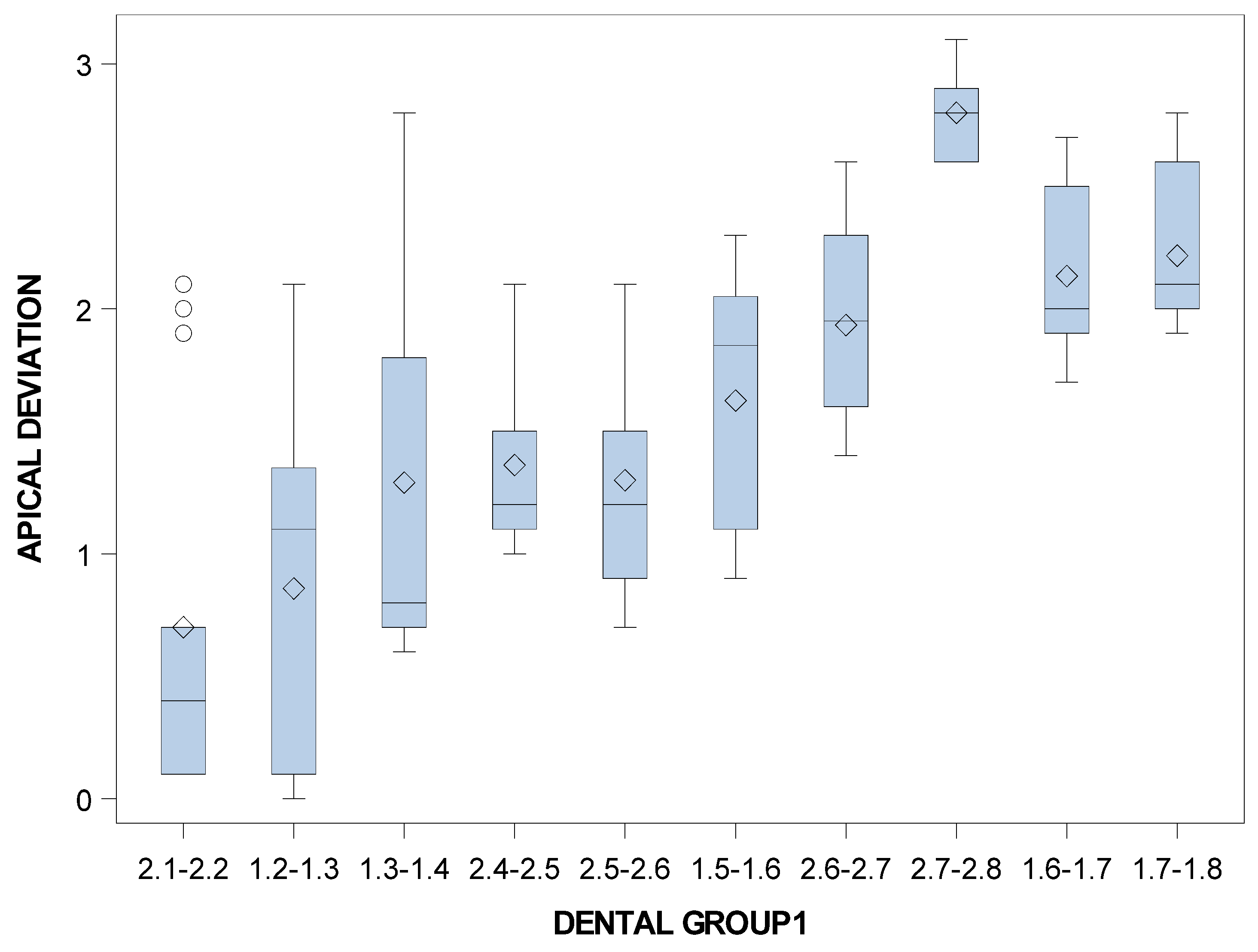
| n | Mean | SD | Minimum | Maximum | |
|---|---|---|---|---|---|
| 2.1–2.2 | 14 | 0.70 | 0.78 | 0.10 | 2.10 |
| 1.2–1.3 | 14 | 0.86 | 0.80 | 0.00 | 2.10 |
| 1.3–1.4 | 13 | 1.29 | 0.87 | 0.60 | 2.80 |
| 2.4–2.5 | 14 | 1.36 | 0.37 | 1.00 | 2.10 |
| 2.5–2.6 | 14 | 1.30 | 0.48 | 0.70 | 2.10 |
| 1.5–1.6 | 14 | 1.63 | 0.49 | 0.90 | 2.30 |
| 2.6–2.7 | 13 | 1.93 | 0.39 | 1.40 | 2.60 |
| 2.7–2.8 | 14 | 2.80 | 0.18 | 2.60 | 3.10 |
| 1.6–1.7 | 14 | 2.13 | 0.34 | 1.70 | 2.70 |
| 1.7–1.8 | 14 | 2.22 | 0.33 | 1.90 | 2.80 |
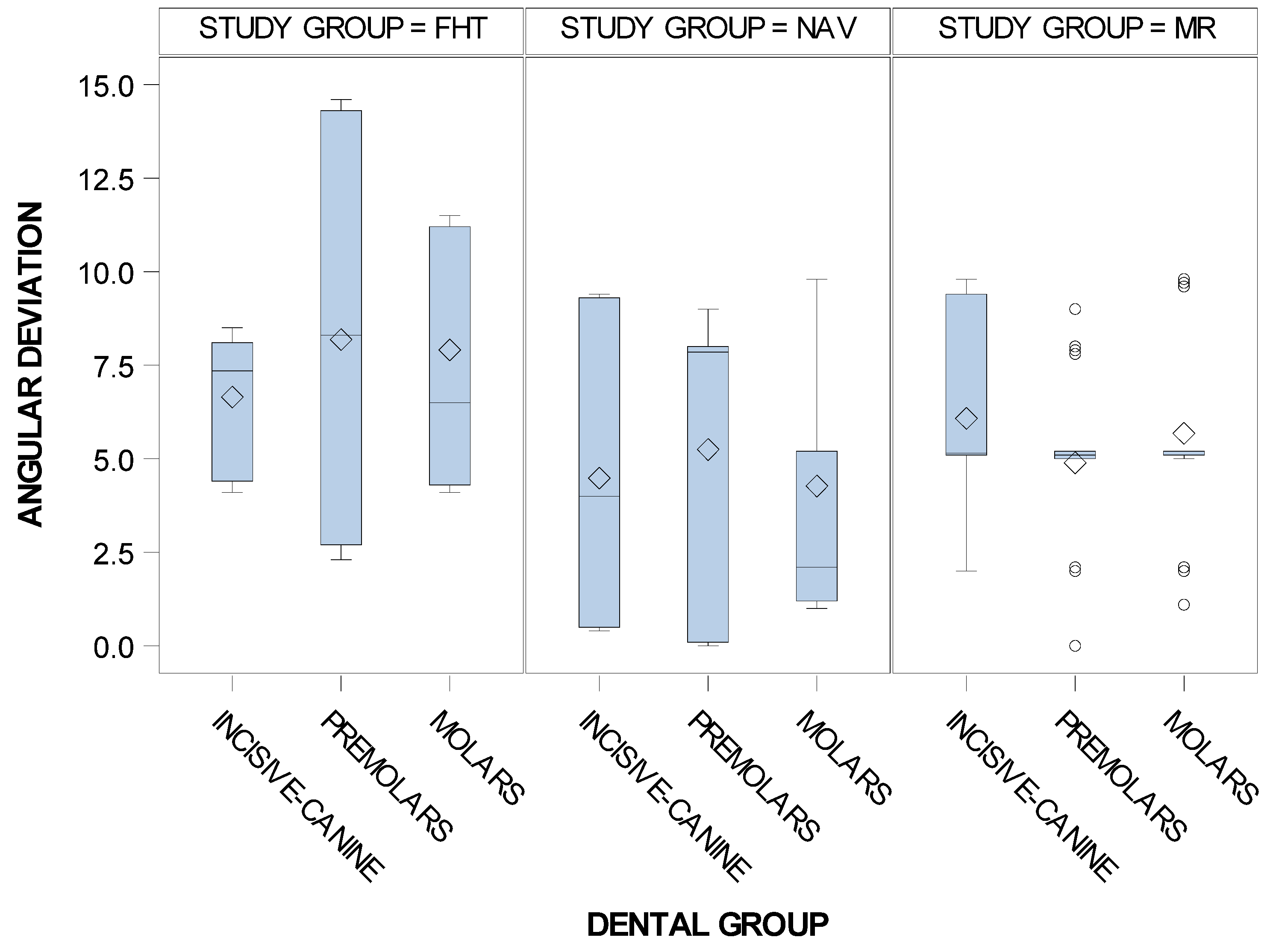
| n | Mean | SD | Minimum | Maximum | ||
|---|---|---|---|---|---|---|
| Inci sive-canine | NAV | 23 | 4.48 | 3.67 | 0.40 | 9.40 |
| MR | 23 | 6.08 | 2.65 | 2.00 | 9.80 | |
| FHT | 23 | 6.65 | 1.72 | 4.10 | 8.50 | |
| Premolar | NAV | 23 | 5.25 | 4.03 | 0.00 | 9.00 |
| MR | 23 | 4.89 | 2.19 | 0.00 | 9.00 | |
| FHT | 23 | 8.18 | 4.98 | 2.30 | 14.60 | |
| Molar | NAV | 23 | 4.27 | 3.32 | 1.00 | 9.80 |
| MR | 23 | 5.68 | 2.47 | 1.10 | 9.80 | |
| FHT | 23 | 7.91 | 2.99 | 4.10 | 11.50 |
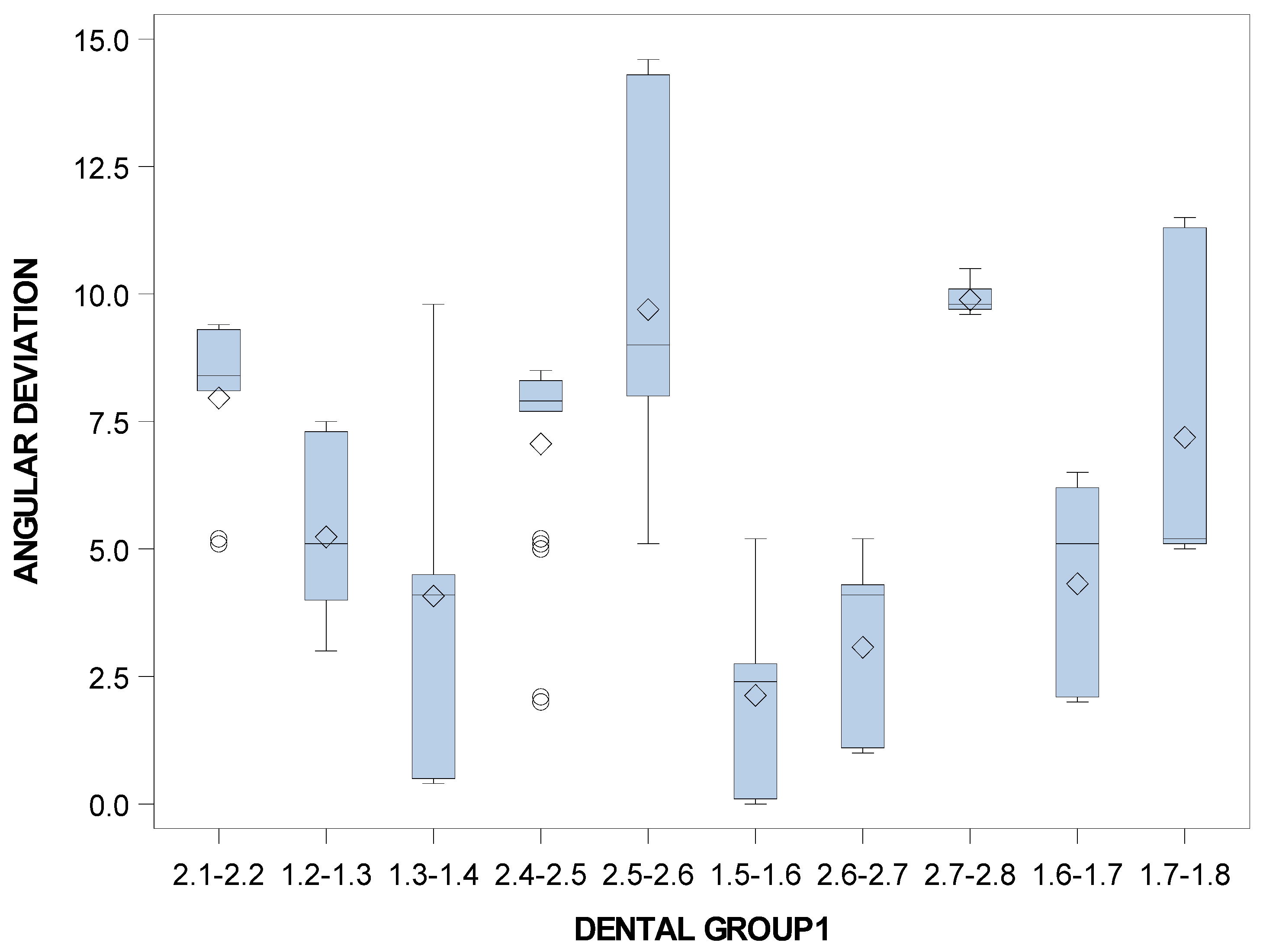
| n | Mean | SD | Minimum | Maximum | |
|---|---|---|---|---|---|
| 2.1–2.2 | 14 | 7.96 | 1.69 | 5.10 | 9.40 |
| 1.2–1.3 | 14 | 5.24 | 1.67 | 3.00 | 7.50 |
| 1.3–1.4 | 13 | 4.08 | 3.60 | 0.40 | 9.80 |
| 2.4–2.5 | 14 | 7.06 | 1.98 | 2.00 | 8.50 |
| 2.5–2.6 | 14 | 9.70 | 3.70 | 5.10 | 14.60 |
| 1.5–1.6 | 14 | 2.13 | 1.93 | 0.00 | 5.20 |
| 2.6–2.7 | 13 | 3.07 | 1.76 | 1.00 | 5.20 |
| 2.7–2.8 | 14 | 9.89 | 0.28 | 9.60 | 10.50 |
| 1.6–1.7 | 14 | 4.32 | 1.91 | 2.00 | 6.50 |
| 1.7–1.8 | 14 | 7.19 | 3.02 | 5.00 | 11.50 |
Publisher’s Note: MDPI stays neutral with regard to jurisdictional claims in published maps and institutional affiliations. |
© 2021 by the authors. Licensee MDPI, Basel, Switzerland. This article is an open access article distributed under the terms and conditions of the Creative Commons Attribution (CC BY) license (https://creativecommons.org/licenses/by/4.0/).
Share and Cite
Riad Deglow, E.; Toledano Gil, S.; Zubizarreta-Macho, Á.; Bufalá Pérez, M.; Rodríguez Torres, P.; Tzironi, G.; Albaladejo Martínez, A.; López Román, A.; Hernández Montero, S. Influence of the Computer-Aided Static Navigation Technique and Mixed Reality Technology on the Accuracy of the Orthodontic Micro-Screws Placement. An In Vitro Study. J. Pers. Med. 2021, 11, 964. https://doi.org/10.3390/jpm11100964
Riad Deglow E, Toledano Gil S, Zubizarreta-Macho Á, Bufalá Pérez M, Rodríguez Torres P, Tzironi G, Albaladejo Martínez A, López Román A, Hernández Montero S. Influence of the Computer-Aided Static Navigation Technique and Mixed Reality Technology on the Accuracy of the Orthodontic Micro-Screws Placement. An In Vitro Study. Journal of Personalized Medicine. 2021; 11(10):964. https://doi.org/10.3390/jpm11100964
Chicago/Turabian StyleRiad Deglow, Elena, Sergio Toledano Gil, Álvaro Zubizarreta-Macho, María Bufalá Pérez, Paulina Rodríguez Torres, Georgia Tzironi, Alberto Albaladejo Martínez, Antonio López Román, and Sofía Hernández Montero. 2021. "Influence of the Computer-Aided Static Navigation Technique and Mixed Reality Technology on the Accuracy of the Orthodontic Micro-Screws Placement. An In Vitro Study" Journal of Personalized Medicine 11, no. 10: 964. https://doi.org/10.3390/jpm11100964