Article

3D Measurement of Structured Specular Surfaces Using Stereo Direct Phase Measurement Deflectometry

1
EPSRC Advanced Metrology Hub, University of Huddersfield, Huddersfield HD1 3DH, UK
2
School of Mechanical Engineering, Hebei University of Technology, Tianjin 300130, China
*
Author to whom correspondence should be addressed.
Machines 2021, 9(8), 170; https://doi.org/10.3390/machines9080170
Submission received: 2 July 2021 / Revised: 13 August 2021 / Accepted: 13 August 2021 / Published: 17 August 2021
(This article belongs to the Special Issue Precision Measurement and Machines)

Abstract

:
With the rapid development of modern manufacturing processes, ultra-precision structured freeform surfaces are being widely explored for components with special surface functioning. Measurement of the 3D surface form of structured specular objects remains a challenge because of the complexity of the surface form. Benefiting from a high dynamic range and large measuring area, phase measurement deflectometry (PMD) exhibits great potential in the inspection of the specular surfaces. However, the PMD is insensitive to object height, which leads to the PMD only being used for smooth specular surface measurement. Direct phase measurement deflectometry (DPMD) has been introduced to measure structured specular surfaces, but the surface form measurement resolution and accuracy are limited. This paper presents a method named stereo-DPMD for measuring structured specular objects by introducing a stereo deflectometor into DPMD, so that it combines the advantages of slope integration of the stereo deflectometry and discontinuous height measurement from DPMD. The measured object is separated into individual continuous regions, so the surface form of each region can be recovered precisely by slope integration. Then, the relative positions between different regions are evaluated by DPMD system to reconstruct the final 3D shape of the object. Experimental results show that the structured specular surfaces can be measured accurately by the proposed stereo-DPMD method.

1. Introduction

With the emergence of ultra-precision manufacturing technology, a large number of complex and precision components and objects were fabricated to meet various needs, which pushed the development of many cutting-edge industries (such as aerospace, automobile manufacturing, large scale integrated circuit, etc.). The precision 3D data of the objects is a basic evaluation criterion of their machining accuracy and also an important guarantee for their functions and surface properties [1]. Therefore, the 3D shape measurement has gradually become an indispensable part of modern industry, and a precise detection will greatly improve the quality of the products [2,3]. The three-coordinate measuring machine (CMM) has been utilized to obtain the spatial coordinates of the object points with a probe for many years; its principle is simple but time-consuming and easily causes scratches on the surface, which may damage the surface property [4]. With the concept of nondestructive inspection and the progress of computer technology and electronics devices, the optical 3D measurement methods with the advantages of non-contact operation and dense-data acquisition have been widely explored [5,6,7]. The fringe projection technique is a typical optical measurement method [8,9]. When the coded fringe pattern is projected onto the measured surface, the image is modulated by the topography of the surface. Once the deformed fringe pattern is demodulated, the 3D coordinate of the measured surface can be accurately obtained. After years of development, the fringe projection technology has made great progress in speed, accuracy, size, and other measurement aspects. However, this technique is only suitable for diffused surface measurement. When the coded fringe pattern is projected onto a specular surface, like an astronomical telescope, car windshield, painted body, polished mechanical parts, and so on, light spots appear on the tested surface, so that the shape information is difficult to retrieve from the deformed patterns. A traditional way to solve this problem is to spray coating materials on the specular surface to make it show diffuse reflection characteristics, then the fringe projection technique can be applied to obtain its 3D data, but this behavior may damage the optical properties of the precision specular surface [10].
In order to flexibly measure the specular surfaces and satisfy various kinds of engineering demands, some optical methods that cleverly use the reflective characteristics of the specular surface have been proposed [11,12,13,14]. Among these techniques, interferometry and PMD technology demonstrate great advantages [15,16]. Interferometry is the most accurate optical measurement technology. Based on the principle of light wave superposition, it obtains the relevant information of the object by analyzing the alternating light and dark interference fringes. The surface form determined by this method often has a sub-nanometer resolution [17,18]. However, it is difficult to measure a specular object with complicated surfaces, especially a free-form surface, and usually requires expensive auxiliary equipment. PMD does not have these restrictions. Its simple system structure, large measuring area, and high dynamic range give it more applicability in the measurement of specular surfaces.
As commonly known, when a camera is used to shoot a specular object, the image captured by the camera is not the texture image of the target object, but a virtual image of the surrounding environment reflected by the object. Moreover, the reflected image is distorted by the topography of the object. PMD technology takes the advantage of this fact to reconstruct the 3D shape of the object [19,20,21]. In order to weaken the brightness of the light source and avoid the light spots on the measured specular surface, the coded sinusoidal fringe pattern is displayed on a liquid crystal display (LCD) screen as the input source, and then a camera is utilized to collect the deformed patterns reflected by the object. Then the slope information of the measured object is obtained through the phase difference between the input fringe pattern and the deformed pattern. Finally, an integral algorithm is implemented to recover the 3D shape of the object [22,23]. Su et al. proposed a software-configurable optical test system for the measurement of large, highly aspherical shapes; the spatial relationship between the imaging point, the measured point, and the corresponding screen pixel is set up to reconstruct the 3D shape of the object [24]. However, this system is mostly used for measuring the regular specular surfaces (i.e., spherical or aspherical mirrors). Knauer et al. established a stereo deflectometry system, in which two cameras were used to capture the reflected fringe patterns [25]. By assuming the spatial position of a measured point along its reflected ray, two normal vectors with respect to different cameras are obtained. Then, the uniqueness of the normal vector of the object point is used to identify the real slope value, and finally the 3D shape is recovered by slope integration. This method seriously relies on the system calibration accuracy, otherwise it will get an inaccurate result. Graves et al. presented a model-free iteration deflectometry approach, which takes no input model. The relationship between phase, slope, and height is correlated by system parameters, and the iteration strategy is applied to get a converged reconstruction surface [26]. It provides an accurate 3D measurement result, but the multiple integrations lead to a continuously accumulating system error. To eliminate the system error in each cycle, Wang et al. introduced a system error control method with rotation self-shearing into the iteration circle, and then the measured points were iteratively corrected according to the reconstructed surface [27]. Furthermore, some dynamic specular surfaces measurement methods were proposed, only one fringe pattern is required in these methods. Huang et al. built a monoscopic fringe reflection system with a two-dimensional Fourier algorithm [28]. In this case, a composite fringe pattern is used for the measurement of dynamic specular surfaces. Later, Wu et al. replaced the cross grating with a color-encoded fringe pattern to solve the spectrum overlapping problem [29]. Additionally, the color intensity crosstalk problem between the three channels is discussed in their study, and the results show that it seldom affects the phase accuracy. All the methods mentioned above retrieve the topography of the object by slope integration. Even though they guarantee high precision, the integration process makes them unable to measure structured specular surfaces.
To tackle this issue, some other PMD models that can directly calculate the height data of the tested surface through phase change were explored. Guo et al. moved the LCD screen parallel to several positions, then the incident light was fitted by the least square method to solve the intrinsic height-slope ambiguity problem in PMD technology, thus the spatial position of each object point was acquired without slope integration [30]. However, the physical movement of the LCD screen may introduce errors. To avoid moving of the device, a method named direct PMD (DPMD) is put forward [31], in which two LCD screens are introduced to construct the incident ray and a reference plane mirror is used to evaluate the topography of the measured surface. In a properly configured DPMD system, suppose R is a point on the reference plane mirror, and it reflects the information of pixel R1 on the first LCD plane and pixel R2 on the second LCD plane into point m in the camera image plane. The reflected ray of R can be easily obtained by connecting point m and the optical center o of the camera. Subsequently, the physical positions of R1 and R2 are positioned by the phase values collected by m, and then the incident light R 1 R 2 is determined. When the measured object is placed in front of the reference plane, it is assumed that point M on the measured surface reflects the screen pixels into m. Since m only collects information along m o , the reflected rays of R and M coincide, and the incident ray of M is achieved by the new phase value collected by m. Finally, the height information of M can be deduced by the geometric relationship between incident rays and reflected ray. Therefore, the DPMD technique is not only displacement-free, but it can also calculate the height value of each object point independently, which means it has the ability to measure specular objects having isolated surfaces. However, compared to the height change of the surface, PMD technology is more sensitive to slope variation, which leads to the fact that the accuracy of DPMD is far lower than the accuracy of the object shape reconstructed by the slope integration method [32].
Considering the limitations of the existing PMD technologies, we proposed a stereo-DPMD method to realize the high accuracy measurement of structured specular surfaces. In our method, a camera is added into the DPMD measurement system to obtain the slope data of the measured surface. The measured structured specular object is separated into individual continuous regions, hence, the topography of each region can be obtained accurately by slope integration. Meanwhile, the advantage of the original DPMD system that can calculate the height information of discrete object points is maintained, so the 3D shape of the measured object is reconstructed by combining the topography and spatial position of each continuous surface.
The rest of the paper is organized as follows. Section 2 presents the stereo-DPMD system, the height and slope calculation geometric model is introduced, and the measurement principle of the structured specular surfaces is also demonstrated. The system parameters that need to be calibrated are analyzed in Section 3. Moreover, a global optimization calibration method is demonstrated. In 
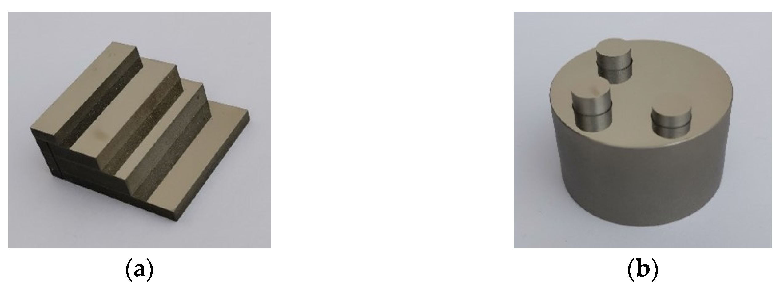
Section 4, an experimental setup is calibrated and two structured specular objects are measured to verify the feasibility of the proposed method. Section 5 summarizes the paper.

2. Materials and Methods

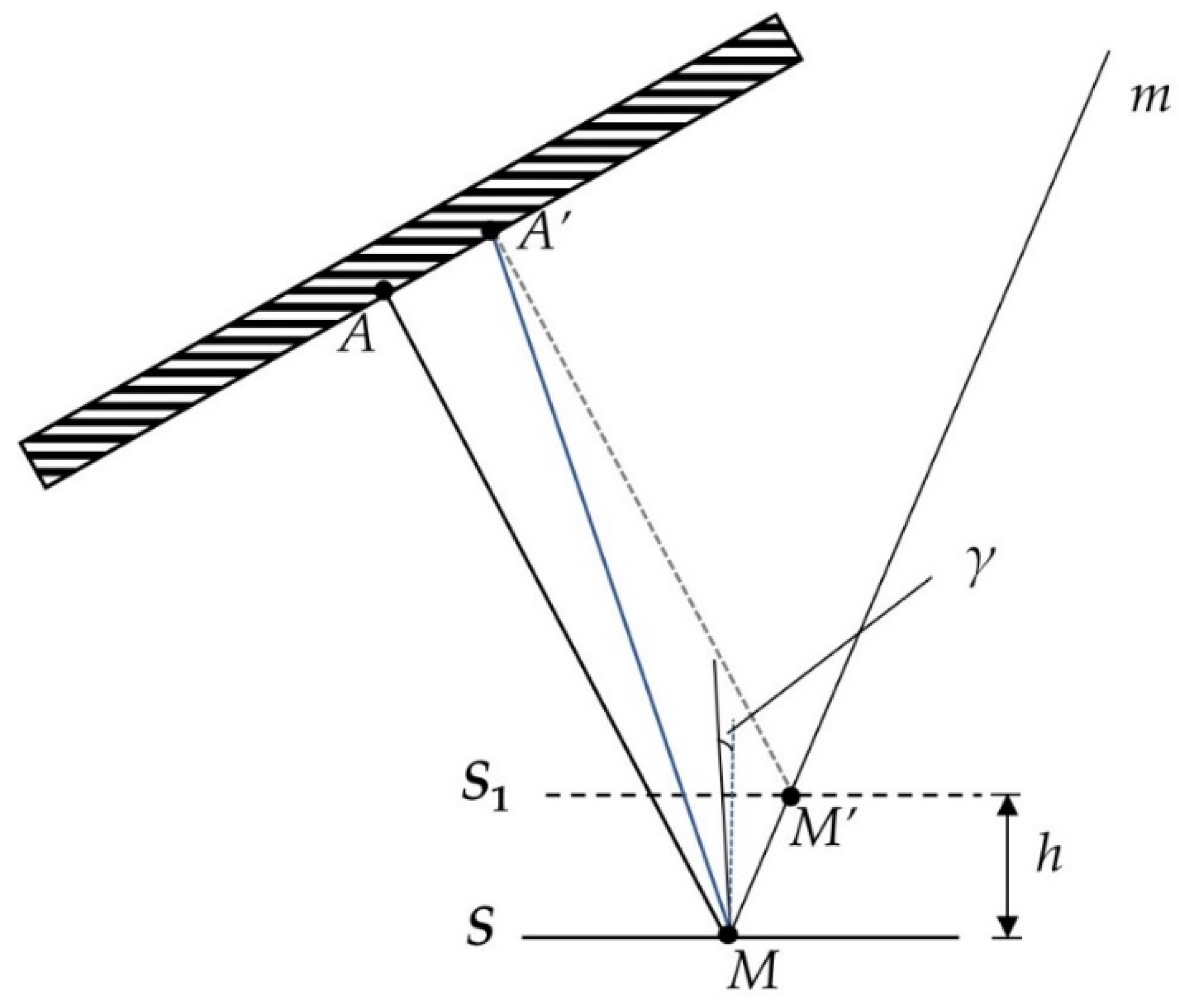
In PMD technology, the deformed fringe pattern reflected by the object contains the shape information of the measured surface, and its absolute phase information is used to calculate the slope field or height dataset of the surface. Nevertheless, limited by the accuracy of the phase calculation algorithm and various noises in the measurement, phase error is inevitable. Thus, the PMD measurement models with higher phase error tolerance can obtain better reconstruction results [32,33]. The influence of the phase error on the measurement results is analyzed, as shown in Figure 1. The phase information φ A of A is collected by point m in the camera image plane after being reflected by point M on the surface S. However, the phase error makes the actual calculated phase value of m be φ A , which causes the incident point to be wrongly positioned at point A’. If the height information of the measured point is deduced directly from this reflection, a point M’ on the surface S1 will be searched as the real point M. The slope values of M and M’ are equivalent, while the height difference between them is h. However, if the surface is expected to be recovered with a slope integration algorithm, A’ will be taken as the incident point and m as the imaging point to solve the slope data of the point under test; its corresponding incident ray changes from AM to AM, and the slope error is γ. It can be seen clearly from Figure 1 that the anti-noise performance of slope data is better than that of height data, and the relevant formula derivation can be found in [32]. Therefore, slope integration is the key step to obtain high accuracy measurements of specular surfaces.
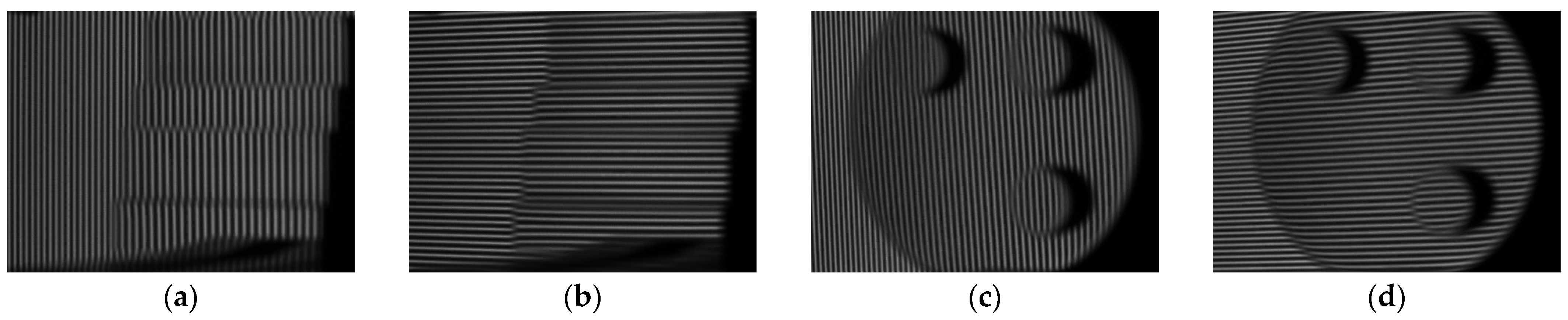
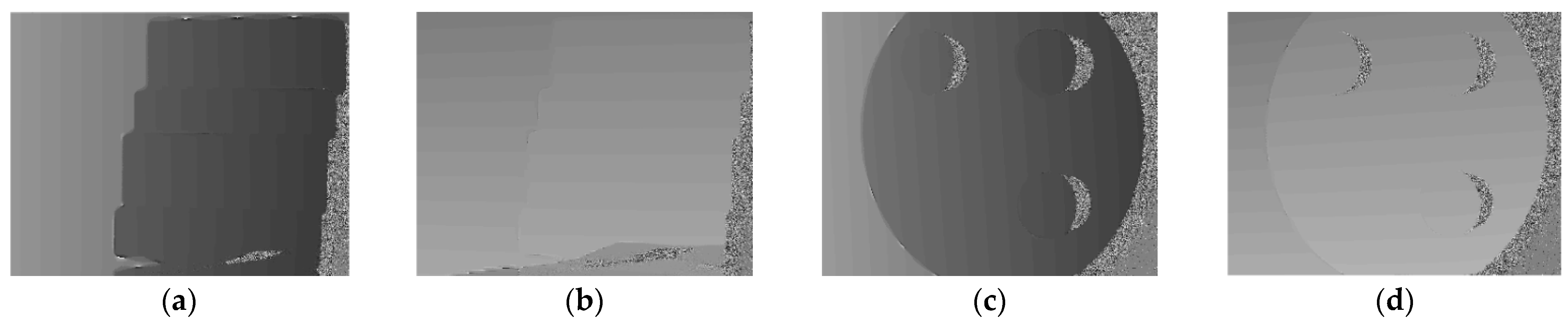
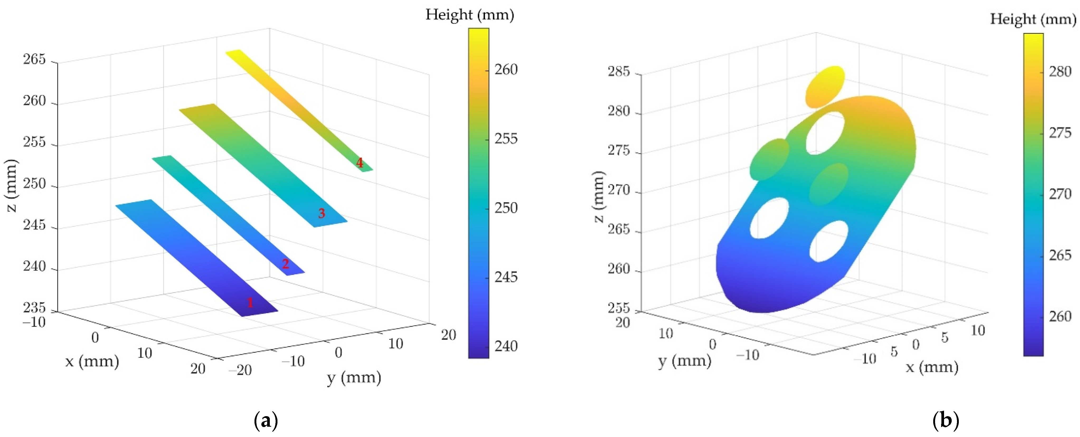
However, the nature of the integration algorithm makes it impossible to reconstruct the 3D shape of structured specular surfaces. Incorrect height data appears at the edges of two discontinuous surfaces and is then accumulated into the height calculation process of other surfaces. The reason for this phenomenon is that the height of discontinuous edge points cannot be simply calculated with the slope data and step length of adjacent edge points. Therefore, we proposed a stereo-DPMD method to perform the high precision 3D measurement of structured specular surfaces. The measured object is separated into individual continuous surfaces, and the relative positions between different surfaces are estimated by a DPMD model, then the topography of each isolated surface is accurately achieved by slope integration. Finally, the topography and spatial position of each surface are fused to reconstruct the 3D shape of the structured specular object.
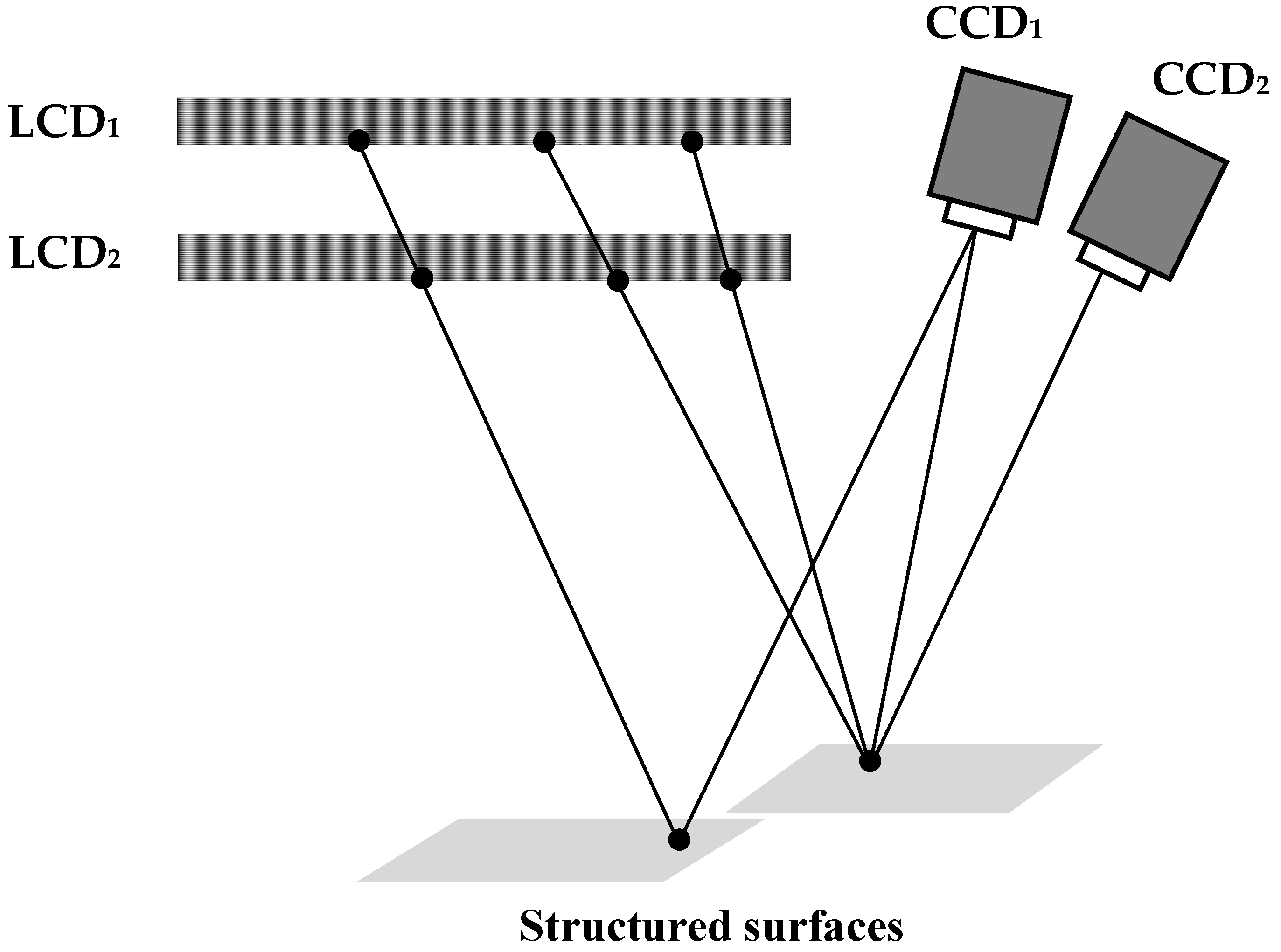
Figure 2 shows the schematic setup of the stereo-DPMD technology. It includes two LCD screens, LCD1 and LCD2, which are parallel; two charge coupled device (CCD) cameras; and the measured object. In the system, the two LCD screens and CCD1 make up the DPMD system to evaluate the relative position between the two different isolated surfaces, the two CCD cameras and LCD1 form the stereo deflectometry model for the calculation of the slope field. When the sinusoidal fringe patterns are displayed onto the LCD screens, the CCD cameras collect the images reflected by the object. Then, the absolute phase information of the deformed fringe patterns is calculated to retrieve the 3D shape of the object through system parameters.
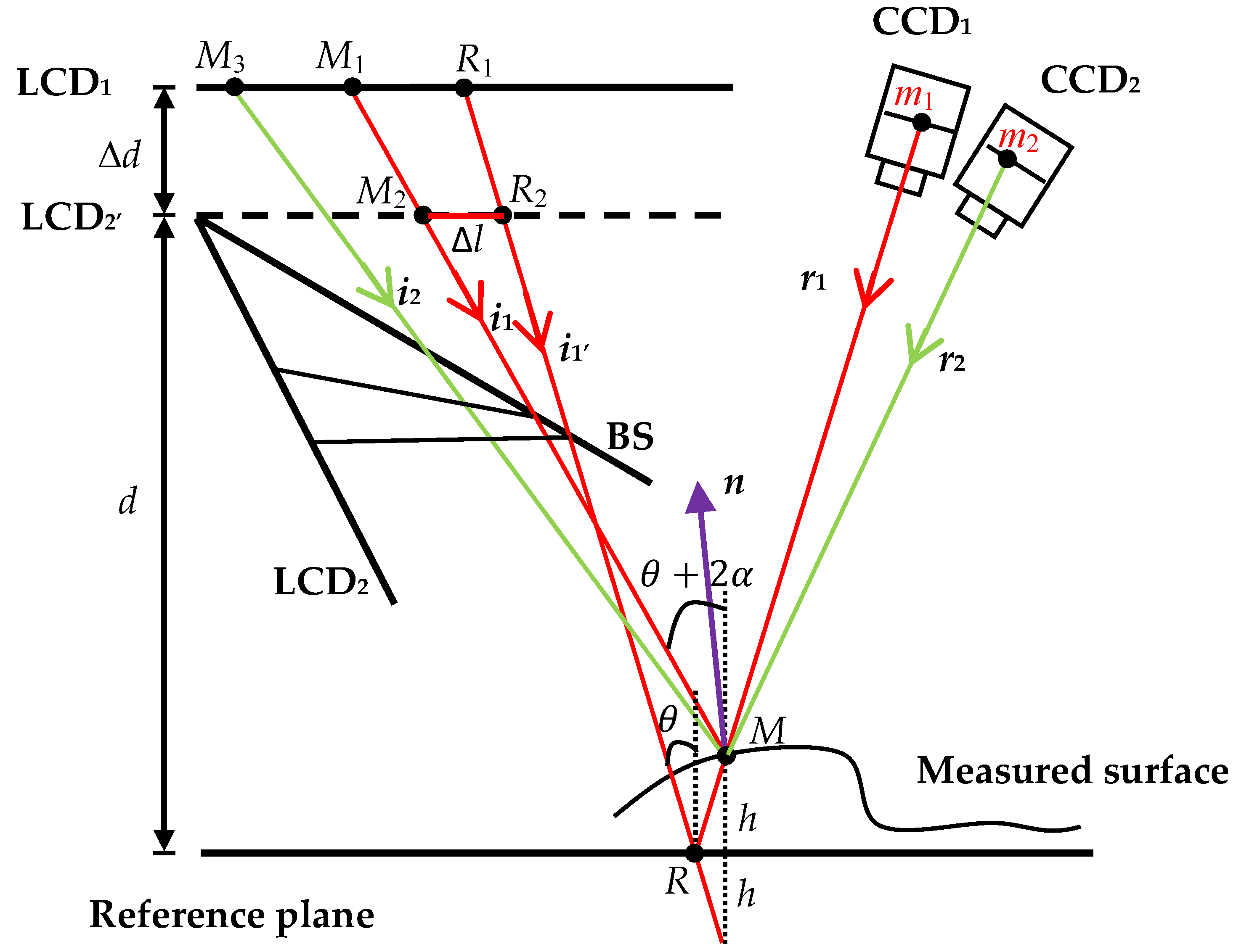
The mathematical model is demonstrated in 
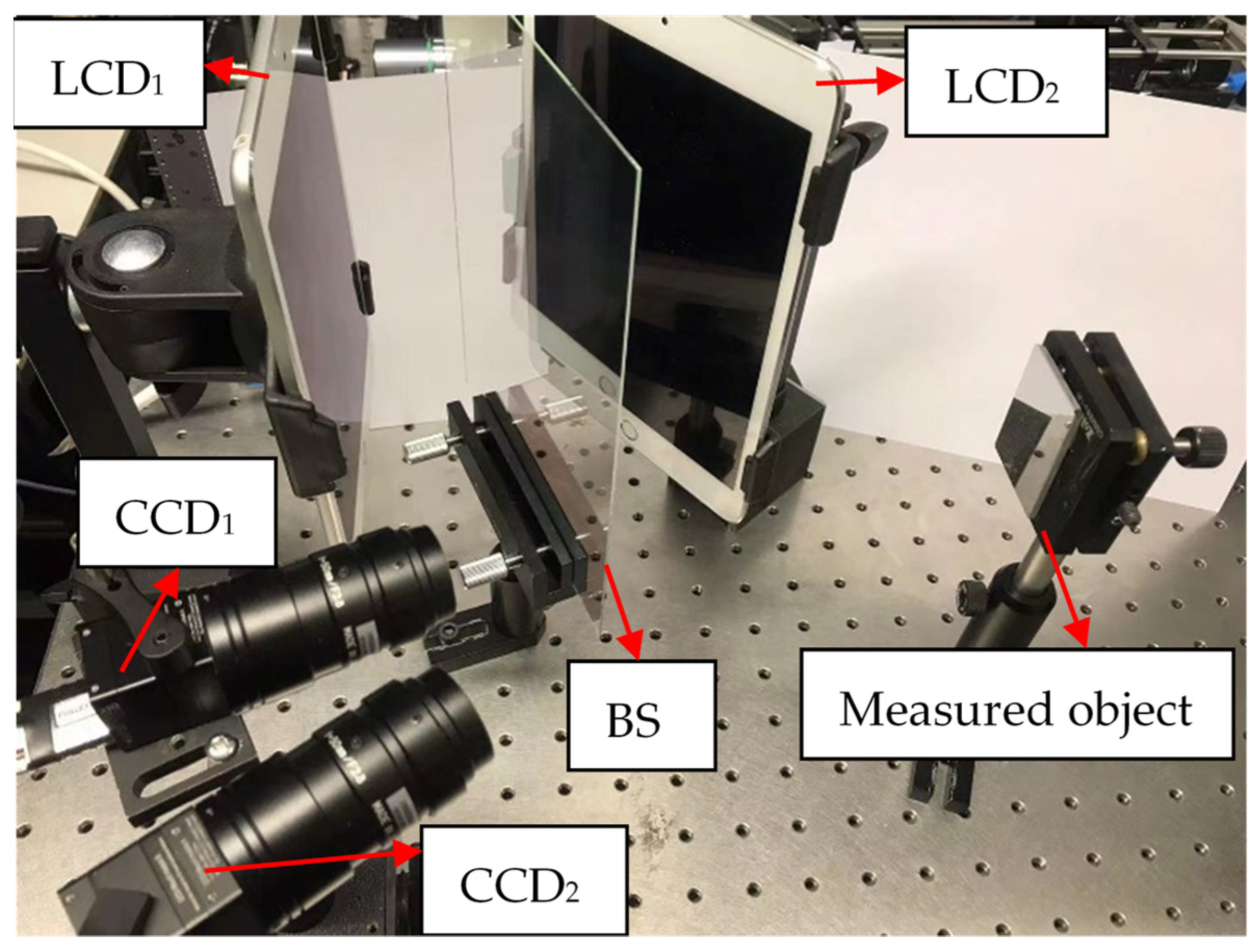
Figure 3. A beam splitter (BS) is utilized to avoid the occlusion of LCD1 by LCD2. The BS is placed at a position where the virtual image of the LCD2 screen LCD2′ is parallel to LCD1. Additionally, a reference plane mirror is added to assist the measurement, and this plane mirror is located parallel to the two LCD screens. In Figure 3, the distance between LCD2′ and LCD1 is Δd, and the distance between LCD2′ and the reference mirror is d.
For a point R on the reference plane, its reflected ray r1 passes through the optical center of CCD1 and imaged at point m1. Based on the phase information recorded by m1, the corresponding screen points R1 on LCD1 and R2 on LCD2′ are acquired, then the incident light i1′ is determined accordingly. When a measured object is placed in front of the plane mirror, the reflected ray collected by pixel m1 still passes through the optical center, so its direction remains unchanged. However, the height and slope change of the measured point (from R to M) varies the incident ray from i1′ to i1. The corresponding screen pixels locate at M1 and M2. According to the geometrical relationship in Figure 2, the following equations are obtained, in which φ X denotes the vertical phase data of point X, q is the physical period of fringe pattern, θ and θ + 2 α are the incident angles of i1′ and i1, α is the angle difference between the normal vectors of R and M, and Δ l represents the horizontal distance between R2 and M2.
q ( φ M 1 φ M 2 ) 2 π = Δ d tan ( θ + 2 α ) q ( φ R 1 φ R 2 ) 2 π = Δ d tan θ q ( φ M 2 φ R 2 ) 2 π = Δ l ( d + h ) tan θ + Δ l = ( d h ) tan ( θ + 2 α )
Then, the height information of the point M can be deduced by [28]:
h = d [ ( φ M 1 φ M 2 ) ( φ R 1 φ R 2 ) ] Δ d ( φ M 2 φ R 2 ) ( φ M 1 φ M 2 ) + ( φ R 1 φ R 2 ) .
Equation (2) shows that a well-deployed DPMD system is capable of acquiring the height dataset of the structured specular object and can reconstruct its 3D topography. However, to improve the measurement accuracy of each isolated surface, the slope field of the object is calculated. The horizontal and vertical sinusoidal fringe patterns are displayed on LCD1 screen, then the patterns reflected by the object are captured by CCD1 and CCD2 simultaneously. An imaging point m is selected to make an inverse ray tracing. Its reflected ray r1 is still determined by the pinhole model, and its screen pixel M1 is acquired based on the phase value captured by m. Assuming that the point M on r1 is the measured point, the second reflected ray r2 of point M with respect to CCD2 is achieved by linking M with the optical center of CCD2, which intersects the image plane of CCD2 at point m2. Then, by looking up the phase value of m2 on the LCD1 plane, the screen point M3 can be found, and a new reflection relation is formed. At this time, two normal vectors n k (k = 1 or 2) of the point M can be calculated through two groups of incident rays and reflected rays ( i 1 , r 1 ) / ( i 2 , r 2 ) .
n k = i k + r k .
Subsequently, the fact that the target point M has only one normal vector is used to distinguish the real slope data. If n1 and n2 are equal, the correct slope information is obtained, otherwise a new point on r1 will be reassumed to seek the slope value. Moreover, to tolerate the inevitable systematical error, a threshold is set to stop the point assuming process. When the difference between two normal vectors is less than the threshold, the slope value is acquired.
Then, the slope data of the structured specular object is separated into several continuous fields to eliminate the integration error between the discontinuous edges, and then the 3D shape of each isolated surface is reconstructed precisely by slope integration. Note that the integration algorithm has difficulty in determining the absolute position of the surface; the form of each continuous surface obtained by slope integration and the discontinuous depth information calculated by DPMD technology are combined to reconstruct the final 3D shape of the structured specular surfaces.

3. System Calibration

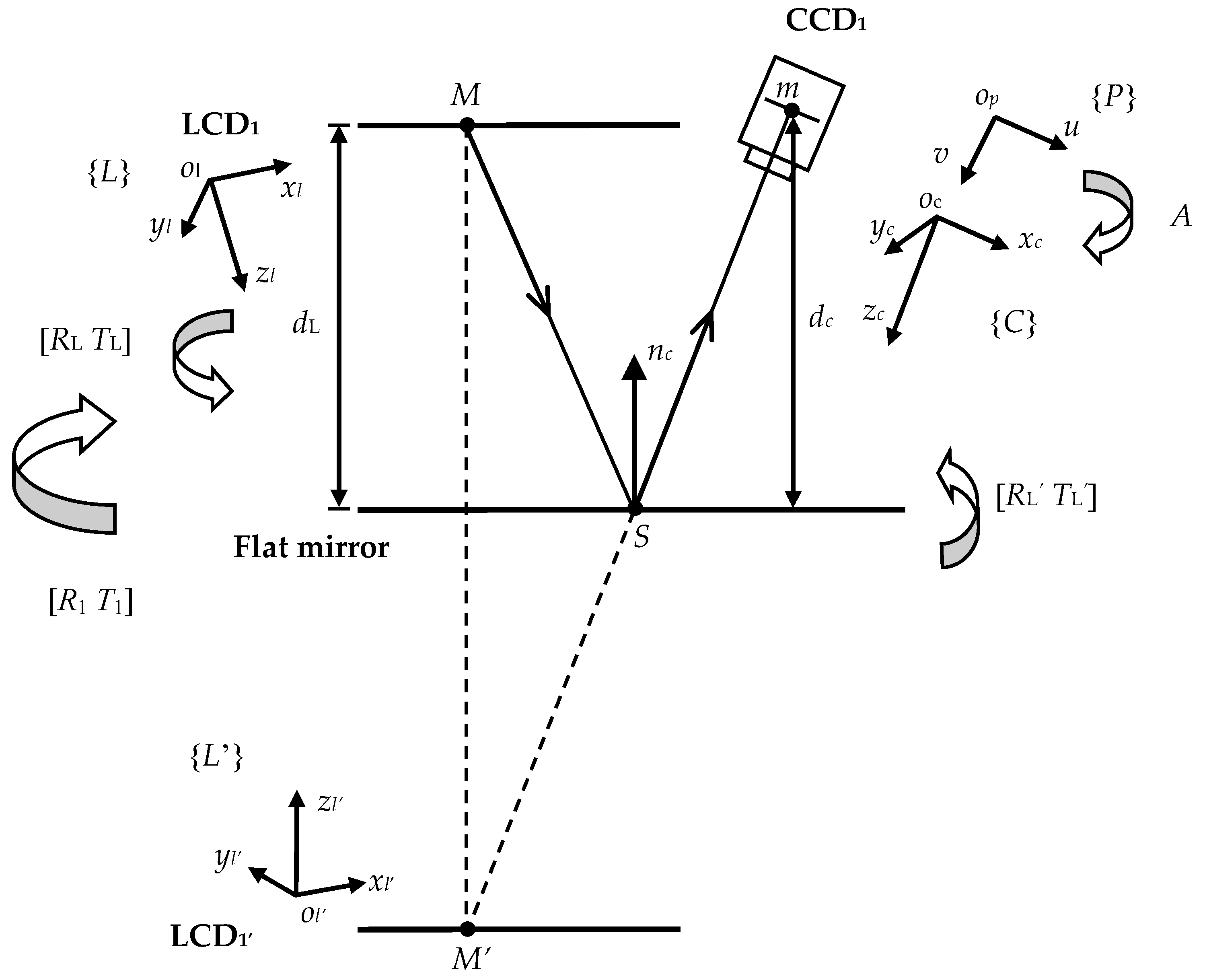
The phase map of the deformed fringe patterns collected by the CCD cameras carries the shape information of the measured object, and the system parameters connect them. It can be seen from Equation (2) that the parameters Δd and d need to be calibrated when the height information of the target point is calculated. Meanwhile, the calculation of surface slope relies on the relative positions between CCD cameras and LCD1 screen. Since the screen is not in the field of view of the cameras, a markless reference plane mirror is used to assist the calibration process.
In order to obtain system parameters accurately, a global optimization calibration algorithm is applied [34]. Take the calibration process between LCD1 and CCD1 as an example, as shown in Figure 4. The horizontal and vertical sinusoidal fringe patterns are sequentially displayed on the LCD1 screen, then the camera captures the virtual images reflected by the plane mirror. A phase unwrapping algorithm is performed to establish the corresponding pairs between the camera and the screen pixels. The LCD screen is assumed to be an ideally flat plane to acquire the physical coordinates of the screen pixels. Thus, for a camera pixel m, its virtual screen pixel M in the mirrored LCD1′ coordinate system can be located uniquely by the phase information recorded by point m:
{ x M = φ u q / ( 2 π ) y M = φ v q / ( 2 π ) .
where ( φ u , φ v ) is the horizontal and vertical phase data collected by point m, ( x M , y M ) is the physical coordinate of M in LCD1′ frame.
Based on the pinhole imaging model, the relative position [RL tL] between LCD1′ and CCD1 can be obtained with the patterns reflected by three arbitrary mirror positions. A is a matrix that contains the internal parameters of the camera, which can be calibrated by Zhang’s method [35], and s is the scale factor:
s m = A [ R L t L ] M .
Subsequently, the relation between the real LCD1 screen and the camera can be acquired by the mirror relationship between LCD1 and LCD1′:
{ R L = ( I 2 n c n c T ) R L t L = ( I 2 n c n c T ) t L + 2 d c n c .
where [RL tL] is the extrinsic matrix of LCD1, nc is the normal vector of the plane mirror and dc is the distance from the mirror to the center of CCD1, with all of these parameters expressed in the CCD1 coordinate system. Since LCD1 screen is fixed, [RL tL] does not change with the posture of the mirror. For two different mirror positions i, j, there are:
R L i = ( I 2 n c i n c i T ) R L R L j = ( I 2 n c j n c j T ) R L
Thus,
R L i = ( I 2 n c i n c i T ) ( I 2 n c j n c j T ) R L j .
Let
R i j = R i R j .
nc can be calculated with three different poses of the plane mirror:
n c i = m i j × m i k m i j × m i k .
where mij is the eigenvector to the eigenvalue 1 of Rij, and k is the kth position of the mirror, k i j . And dc can be deduced by:
[ I n c i n c i T 2 n c i 0 0 I n c j n c j T 0 2 n c j 0 I n c k n c k T 0 0 2 n c k ] [ t L d c i d c j d c k ] = [ t L i t L j t L k ] .
In the same way, the relative position between LCD1 and CCD2 in 
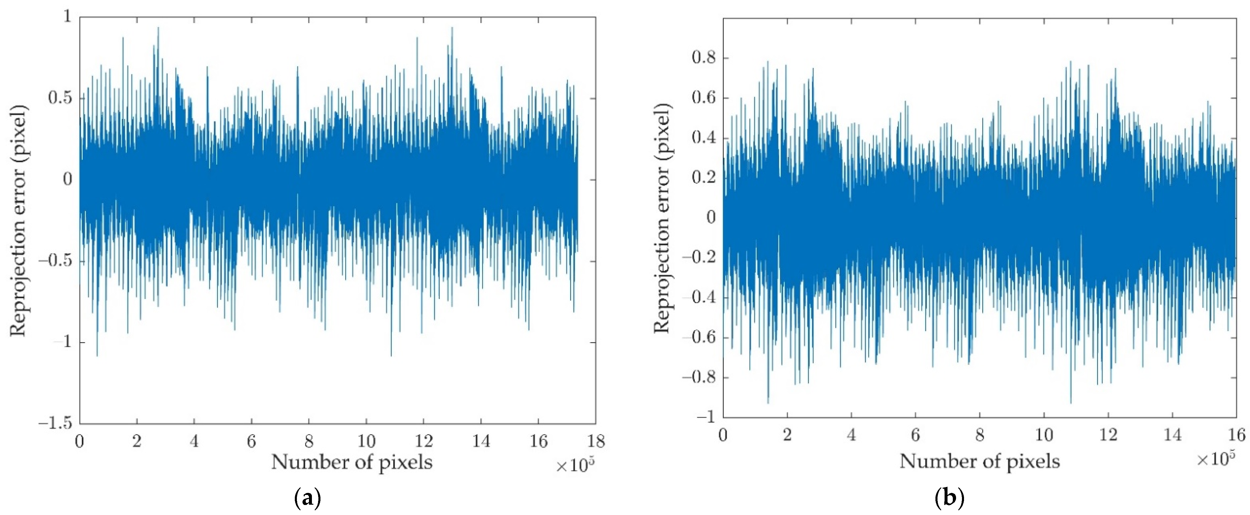
Figure 3 can be achieved. Finally, the system parameters are optimized by minimizing the reprojection error of screen pixels in a cost function [34]. Due to the different values of nc and dc in the two CCD frames, they are converted to the LCD1 coordinate system to simplify the optimization process.
{ n L = R L 1 n c d L = d c n c t L .
where n L is the normal vector of the mirror in LCD1 frame and dL is the distance between LCD1 and the reference mirror. In addition, dL is also the parameter d in Equation (2) that needs to be calibrated in the DPMD system. Using the same method demonstrated above to get the relative position between LCD2′ and CCD1, the distance Δ
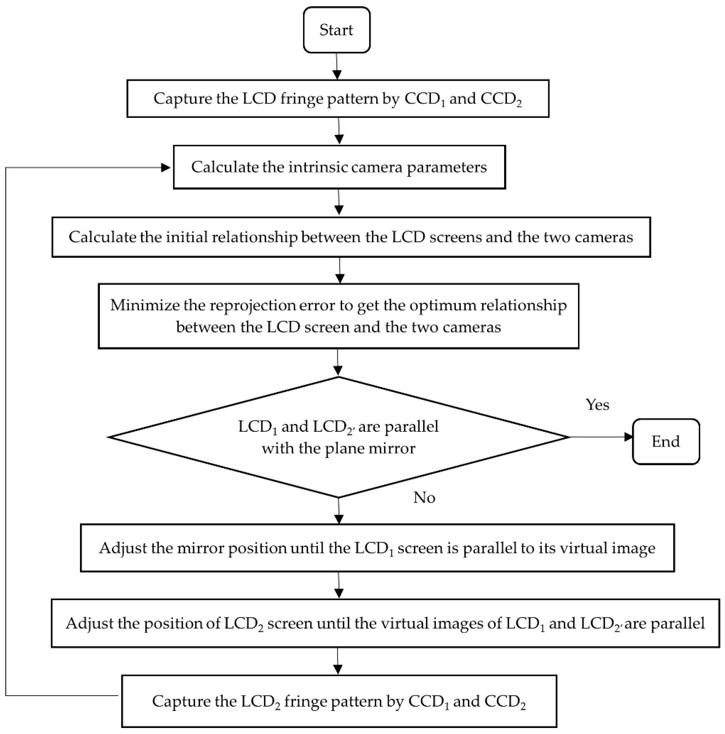
d can be obtained by the differences between the two LCD screens and the reference mirror. The workflow is shown in Figure 5.

4. Experiment

4.1. Setup

A stereo-DPMD system was established, it consists of two LCD screens, two cameras and a beam splitter, as shown in Figure 6. The display screen is an iPad Pro with a resolution of 1366 × 1024 pixels, and the pixel size is 0.192 × 0.192 mm2. The cameras are MQ042RG-CM with a resolution of 2048 × 2048 pixels, and they focus on the fringe pattern reflected by the specular surface. To ensure the stability of the setup, the experimental system was built on an optical table, each LCD screen and each camera was provided with a heavy-duty magnetic base from Thorlabs, and the holders of the beam splitter and the measured object were screwed into the screw holes of the optical table.

4.2. System Calibration

Considering the phase accuracy and the measurement speed, two groups of horizontal and vertical sinusoidal fringe patterns with eight-step phase-shifting and having fringe numbers of 225, 224, and 210 were exhibited on the LCD1 screen. A 4-inch plane mirror with λ / 20 flatness provided with a holder was manually placed at 13 random positions in the common field of view of the two cameras. The distance and angle between the different mirror poses are not strictly required. Then, the fringe patterns reflected by the mirror were captured by the two CCD cameras simultaneously. To reduce the random noise, each pattern was repeatedly captured five times and averaged, which takes more time but leads to an accurate result. Then, the multiple phase-shifting algorithm and three-fringe selection method were implemented to calculate the absolute phase information [36,37]. The calibration method mentioned in Section 3 was performed to acquire the relation between the LCD1 screen and the two cameras. Subsequently, the same fringe patterns were displayed on the LCD2 screen to obtain the relative position between LCD2′ and two cameras with 13 different mirror poses. The final reprojection error distributions of these two calibration processes are shown in Figure 7.
The calibrated normal vectors of LCD1 and LCD2′ in the CCD1 coordinate system are listed in Table 1. The Euler angle differences between the two screens are less than 0.1 degrees, and the normal vectors of the reference plane mirror in LCD1 and LCD2′ frames are [−0.00129 0.00056 −0.99999] and [−0.0009 0.00035 −0.99999], which are approximate to [0 0 −1], so the reference mirror and the two screens (LCD1 and LCD2′) are almost parallel. In addition, a fringe compensation method can be used to eliminate the slight non-parallel between the two screens [38]. The DPMD system parameters Δd and d are 26.2436 mm and 234.1214 mm.

4.3. Measurement Results

To verify the proposed method, two artificial structured specular objects were measured, as shown in Figure 8. The horizontal and vertical sinusoidal fringe patterns were displayed on the LCD screens, and the deformed patterns reflected by the reference mirror and the measured object were recorded by two cameras, as shown in Figure 9. The fringe patterns reflected by the reference mirror were also collected to calculate the topography of the sample, which requires a large depth of field of the camera, otherwise the contrast of the fringe pattern will be decreased.
Then, the absolute phase information was calculated by eight-step phase-shifting algorithm and the optimum three-fringe selection method; the absolute phase maps are listed in Figure 10. Afterwards, the 3D shapes of the two samples were reconstructed, as shown in Figure 11.
Limited by the manufacturing accuracy, the surfaces of the circular step gauge in Figure 11b are not parallel, but it can be seen from its reconstruction results that the proposed method can achieve the measurement of structured specular surfaces. The rectangular gauge in Figure 11a has four parallel planes, so the relative height between adjacent steps can be used to evaluate the measurement accuracy of discontinuous surfaces. By fitting the 3D data of four separate surfaces obtained by the proposed method into ideal planes, the height differences between every two adjacent surfaces can be calculated, as shown in the third column of Table 2. For comparison, the corresponding height data were also measured by CMM (within a measuring accuracy of 2 µm). The measurement of each isolated surface of the sample is realized by measuring the depth information of 8 to 10 points on the surface, and the average of these height data is taken as the height value of the surface. Then, the height difference between the adjacent isolated surfaces can be calculated, as shown in the second column of Table 2. The maximum height difference between these two methods is 32.7 µm, while the minimum value is 21 µm.
The reconstruction accuracy of the continuous surface is judged by calculating the root-mean-square (RMS) value between the fitted surface and its corresponding measured data. At first, the RMS values of the four reconstructed surfaces of the rectangular gauge obtained by the proposed method were calculated. The maximum and minimum RMS values are 141.1 nm and 94.6 nm, as shown in the second row of Table 3. In addition, DPMD has the ability to obtain the height data of each target point, so we also fitted the height data of the isolated surfaces acquired by DPMD and calculated their corresponding RMS values. It can be seen from the third row of Table 3 that when using DPMD to measure continuous areas, the maximum and minimum RMS values are 122 µm and 110 µm respectively. Limited by the manufacturing accuracy, the surfaces of the sample are not ideally flat, which makes the calculated RMS value slightly larger than the real value, otherwise better results can be obtained. However, it is obvious that slope integration has a huge advantage in continuous surface measurement, and its sensitivity to phase changes makes it thousands of times better than DPMD in continuous surface measurement. Experimental data proves that the proposed method can effectively improve the measurement accuracy of surface topography while maintaining the advantages of DPMD technology for measuring discontinuous surfaces.

5. Conclusions

In this paper, a stereo-DPMD method was proposed to improve the 3D measurement accuracy of structured specular objects. The proposed stereo-DPMD method combines the advantages of slope integration and discontinuous height calculation. By adding a camera to the DPMD system, the height information and the slope data of the tested surface were obtained simultaneously. The structured object was separated into continuous surfaces to guarantee that the topography of each surface could be recovered precisely by a slope integration algorithm. Also, the relative position between different surfaces was determined by the DPMD geometrical model, thus the 3D shape of the measured structured specular object could be reconstructed. In addition, a global calibration method was applied to acquire the optimum relations between the screens and cameras. Based on the external parameters of the LCD screen expressed in camera coordinate system, the parallelism between the screen and the reference mirror was adjusted to meet the height calculation geometrical structure. To verify the feasibility of the proposed stereo-DPMD method, an experimental setup consisting of two LCD screens, two CCD cameras, a BS and a markless plane mirror was established and two specular objects with discontinuous surfaces were measured. Experimental results show that the structured specular surfaces can be accurately measured by the proposed method.

Author Contributions

Conceptualization, Z.Z. and F.G.; methodology, all authors; software, Y.W. and Y.X.; validation, Y.W. and Y.X.; formal analysis, all authors; data curation, Y.W.; writing—original draft preparation, Y.W. and Y.X.; writing—review and editing, Y.W., Z.Z. and F.G.; supervision, F.G., Z.Z. and X.J.; funding acquisition, F.G., Z.Z. and X.J. All authors have read and agreed to the published version of the manuscript.

Funding

This research was funded by the Engineering and Physical Sciences Research Council (EPSRC) of the UK, grant number EP/P006930/1 and EP/T024844/1; the National Natural Science Foundation of China, grant number 52075147.

Institutional Review Board Statement

Not applicable.

Informed Consent Statement

Not applicable.

Data Availability Statement

Not applicable.

Conflicts of Interest

The authors declare no conflict of interest.

References

  1. Sherrington, I.; Smith, E. The significance of Surface topography in engineering. Precis. Eng. 1986, 8, 79–87. [Google Scholar] [CrossRef]
  2. Tang, Y.; Su, X.; Liu, Y.; Jing, H. 3D shape measurement of the aspheric mirror by advanced phase measuring deflectometry. Opt. Express 2008, 16, 15090–15096. [Google Scholar] [CrossRef]
  3. Blais, F. Review of 20 years of range sensor development. J. Electron. Imaging 2004, 13, 231–243. [Google Scholar] [CrossRef]
  4. Mian, S.H.; Al-Ahmari, A. Enhance performance of inspection process on Coordinate Measuring Machine. Measurement 2014, 47, 78–91. [Google Scholar] [CrossRef]
  5. Zhang, Z. Review of single-shot 3D shape measurement by phase calculation-based fringe projection techniques. Opt. Lasers Eng. 2012, 50, 1097–1106. [Google Scholar] [CrossRef]
  6. Zhang, H.; Han, S.; Liu, S.; Li, S.; Ji, L.; Zhang, X. 3D shape reconstruction of large specular surface. Appl. Opt. 2012, 51, 7616–7625. [Google Scholar] [CrossRef]
  7. Tao, T.; Chen, Q.; Da, J.; Feng, S.; Hu, Y.; Zuo, C. Real-time 3-D shape measurement with composite phase-shifting fringes and multi-view system. Opt. Express 2016, 24, 20253–20269. [Google Scholar] [CrossRef]
  8. Wang, Z.; Zhang, Z.; Gao, N.; Xiao, Y.; Gao, F.; Jiang, X. Single-shot 3D shape measurement of discontinuous objects based on a coaxial fringe projection system. Appl. Opt. 2019, 58, 169–178. [Google Scholar] [CrossRef]
  9. Zhang, S. Recent progresses on real-time 3D shape measurement using digital fringe projection techniques. Opt. Laser Eng. 2010, 48, 149–158. [Google Scholar] [CrossRef]
  10. Tao, T.; Guo, H.; He, H. Overview of optical three-dimensional measurement technique for specular reflection surfaces. Opt. Instrum. 2005, 27, 90–95. [Google Scholar]
  11. Kafri, O.; Glatt, I. Moiré deflectometry: A ray deflection approach to optical testing. Opt. Eng. 1985, 24, 246944. [Google Scholar] [CrossRef]
  12. Rosete-Aguilar, M.; Díaz-Uribe, R. Profile testing of spherical surfaces by laser deflectometry. Appl. Opt. 1993, 32, 4690–4697. [Google Scholar] [CrossRef] [PubMed]
  13. Lee, H.-J.; Kim, S.-W. Precision profile measurement of aspheric surfaces by improved Ronchi test. Opt. Eng. 1999, 38, 1041–1047. [Google Scholar] [CrossRef]
  14. Windecker, R.; Haible, P.; Tiziani, H.J. Fast coherence scanning interferometry for measuring smooth, rough and spherical surfaces. J. Mod. Optic. 1995, 42, 2059–2069. [Google Scholar] [CrossRef]
  15. Häusler, G.; Faber, C.; Olesch, E.; Ettl, S. Deflectometry vs. interferometry. Opt. Meas. Syst. Indust. Inspect. VIII 2013, 8788, 87881C. [Google Scholar]
  16. Huang, L.; Idir, M.; Zuo, C.; Asundi, A. Review of phase measuring deflectometry. Opt. Lasers Eng. 2018, 107, 247–257. [Google Scholar] [CrossRef]
  17. Marrugo, A.; Gao, F.; Zhang, S. State-of-the-art active optical techniques for three-dimensional surface metrology: A review. J. Opt. Soc. Am. A 2020, 37, B60–B77. [Google Scholar] [CrossRef]
  18. Davila, A. Wavelength scanning interferometry using multiple light sources. Opt. Express 2016, 24, 5311–5322. [Google Scholar] [CrossRef]
  19. Li, C.; Li, Y.; Xiao, Y.; Zhang, X.; Tu, D. Phase measurement deflectometry with refraction model and its calibration. Opt. Express 2018, 26, 33510–33522. [Google Scholar] [CrossRef]
  20. Liu, D.; Yang, Y.; Tian, C.; Luo, Y.; Wang, L. Practical methods for retrace error correction in nonnull aspheric testing. Opt. Express 2009, 17, 7025–7035. [Google Scholar] [CrossRef]
  21. Xiao, Y.; Su, X.; Chen, W.; Liu, Y. Three-dimensional shape measurement of aspheric mirrors with fringe reflection photogrammetry. Appl. Opt. 2012, 51, 457–464. [Google Scholar] [CrossRef] [PubMed]
  22. Huang, L.; Idir, M.; Zuo, C.; Kaznatcheev, K.; Zhou, L.; Asundi, A. Comparison of two-dimensional integration methods for shape reconstruction from gradient data. Opt. Lasers Eng. 2015, 64, 1–11. [Google Scholar] [CrossRef]
  23. Ren, H.; Gao, F.; Jiang, X. Improvement of high-order least-squares integration method for stereo deflectometry. Appl. Opt. 2015, 54, 10249–10255. [Google Scholar] [CrossRef] [PubMed]
  24. Su, P.; Parks, R.; Wang, L.; Angel, R.; Burge, J. Software configurable optical test system: A computerized reverse Hartmann test. Appl. Opt. 2010, 49, 4404–4412. [Google Scholar] [CrossRef] [PubMed]
  25. Knauer, M.; Kaminski, J.; Häusler, G. Phase measuring deflectometry: A new approach to measure specular free-form surfaces. Int. Soc. Opt. Photonics 2004, 5457, 366–376. [Google Scholar]
  26. Graves, L.R.; Choi, H.; Zhao, W.; Oh, C.J.; Su, P.; Su, T.; Kim, D.W. Model-free deflectometry for freeform optics measurement using an iterative reconstruction technique. Opt. Lett. 2018, 43, 2110–2113. [Google Scholar] [CrossRef]
  27. Wang, R.; Li, D.; Zhang, X. Systematic error control for deflectometry with iterative reconstruction. Measurement 2021, 168, 108393. [Google Scholar] [CrossRef]
  28. Huang, L.; Ng, C.; Asundi, A. Dynamic three-dimensional sensing for specular surface with monoscopic fringe reflectometry. Opt. Express 2011, 19, 12809–12814. [Google Scholar] [CrossRef]
  29. Wu, Y.; Yue, H.; Yi, J.; Li, M.; Liu, Y. Dynamic specular surface measurement based on color-encoded fringe reflection technique. Opt. Eng. 2016, 55, 024104. [Google Scholar] [CrossRef]
  30. Guo, H.; Feng, P.; Tao, T. Specular surface measurement by using least squares light tracking technique. Opt. Lasers Eng. 2010, 48, 166–171. [Google Scholar] [CrossRef]
  31. Liu, Y.; Huang, S.; Gao, N.; Gao, F.; Jiang, X. Full-field 3D shape measurement of discontinuous specular objects by direct phase measuring deflectometry. Sci. Rep. 2017, 7, 1–8. [Google Scholar] [CrossRef] [PubMed]
  32. Xu, Y.; Gao, F.; Jiang, X. Performance analysis and evaluation of geometric parameters in stereo deflectometry. Engineering 2018, 4, 806–815. [Google Scholar] [CrossRef]
  33. Liang, L.; Xiao, Y.; Su, Y.; Liu, Y. Phase-measuring deflectometry based on binocular vision. J. Sichuan Univ. Nat. Sci. Ed. 2009, 46, 387–391. [Google Scholar]
  34. Xu, Y.; Gao, F.; Jiang, X. A holistic calibration method with iterative distortion compensation for stereo deflectometry. Opt. Lasers Eng. 2018, 106, 111–118. [Google Scholar] [CrossRef]
  35. Zhang, Z. Flexible camera calibration by viewing a plane from unknown orientations. In Proceedings of the Seventh IEEE International Conference on Computer Vision, Corfu, Greece, 20–25 September 1999; 1, pp. 666–673. [Google Scholar]
  36. Niu, Z.; Xu, X.; Zhang, X.; Wang, W.; Zhu, Y.; Ye, J.; Xu, M.; Jiang, X. Efficient phase retrieval of two-directional phase-shifting fringe patterns using geometric constraints of deflectometry. Opt. Express 2019, 27, 8195–8207. [Google Scholar] [CrossRef]
  37. Towers, C.; Towers, D. Time efficient color fringe projection system for 3D shape and color using optimum 3-frequency selection. Opt. Express 2006, 14, 6444–6455. [Google Scholar]
  38. Zhang, Z.; Guo, J.; Wang, Y.; Huang, S.; Gao, N.; Xiao, Y. Parallel-alignment and correction of two displays in three-dimensional measuring system of specular surfaces. Opt. Precis. Eng. 2017, 25, 289–296. [Google Scholar] [CrossRef]
Figure 1. Effect of phase error.
Machines 09 00170 g001
Figure 2. Measurement diagram.
Machines 09 00170 g002
Figure 3. Mathematical model.
Machines 09 00170 g003
Figure 4. System calibration diagram.
Machines 09 00170 g004
Figure 5. The workflow of the calibration process.
Machines 09 00170 g005
Figure 6. Experimental setup.
Machines 09 00170 g006
Figure 7. Reprojection error: (a) the reprojection error between LCD1 and two cameras; (b) the reprojection error between LCD2′ and two cameras.
Machines 09 00170 g007
Figure 8. Two structured specular surfaces: (a) rectangular step; (b) circular step gauge.
Machines 09 00170 g008
Figure 9. The deformed vertical and horizontal fringe patterns reflected by the structured specular surfaces: (a,b) rectangular step; (c,d) circular step gauge.
Machines 09 00170 g009
Figure 10. Absolute phase maps: (a,b) rectangular step; (c,d) circular step gauge.
Machines 09 00170 g010
Figure 11. The 3D shape of two samples: (a) rectangular step; (b) circular step gauge.
Machines 09 00170 g011
Table 1. The normal vector of LCD screens (units: °).
ScreenNormal Vector in CCD1
Coordinate System
Euler Angle
PitchYawRoll
LCD1[−0.44769 −0.01247 −0.89410]0.8665−153.4064−0.3396
LCD2′[−0.44897 −0.01338 −0.89345]0.8765−153.3228−0.2449
Table 2. The results and errors of the measured specular step (units: mm).
Step HeightCMMOur MethodMeasurement Difference
1–22.99273.01370.0210
2–33.92823.96090.0327
3–44.93924.91440.0248
Table 3. The RMS values between fitted surfaces and measured surfaces (units: µm).
MethodSurface 1Surface 2Surface 3Surface 4
Stereo-DPMD0.14110.12630.11680.0946
DPMD122116112110
Publisher’s Note: MDPI stays neutral with regard to jurisdictional claims in published maps and institutional affiliations.

