Article

Evaluation of the Ability to Accurately Produce Angular Details by 3D Printing of Plastic Parts

by
Andrei Marius Mihalache
1,
Gheorghe Nagîț
1,
Laurențiu Slătineanu
1,
Adelina Hrițuc
1,
Angelos Markopoulos
2 and
Oana Dodun
1,*
1
Department of Machine Manufacturing Technology, Gheorghe Asachi Technical University of Iasi, 700050 Iaşi, Romania
2
Department of Mechanical Engineering, National Technical University of Athens, 15780 Athens, Greece
*
Author to whom correspondence should be addressed.
Machines 2021, 9(8), 150; https://doi.org/10.3390/machines9080150
Submission received: 30 June 2021 / Revised: 22 July 2021 / Accepted: 27 July 2021 / Published: 29 July 2021

Abstract

:
3D printing is a process that has become widely used in recent years, allowing the production of parts with relatively complicated shapes from metallic and non-metallic materials. In some cases, it is challenging to evaluate the ability of 3D printers to make fine details of parts. For such an assessment, the printing of samples showing intersections of surfaces with low angle values was considered. An experimental plan was designed and materialized to highlight the influence of different factors, such as the thickness of the deposited material layer, the printing speed, the cooling and filling conditions of the 3D-printed part, and the thickness of the sample. Samples using areas in the form of isosceles triangles with constant height or bases with the same length, respectively, were used. The mathematical processing of the experimental results allowed the determination of empirical mathematical models of the power-function type. It allowed the detection of both the direction of actions and the intensity of the influence exerted by the input factors. It is concluded that the strongest influence on the printer’s ability to produce fine detail, from the point of view addressed in the paper, is exerted by the vertex angle, whose reduction leads to a decrease in printing accuracy.

1. Introduction

A remarkable expansion, both in manufacturing and in research in different fields, can be seen at present in additive manufacturing.
The manufacturing technologies included in additive manufacturing are based on the gradual generation of a part due to the successive deposition of the material layers through different processes until producing the complete part. In some cases, post-additive-manufacturing operations may be required to fit the part within the prescribed quality parameters. The successive deposition of the layers of material can occur through processes such as fused-deposition modeling, plastic jet printing, selective laser melting, selective laser sintering, digital light processing, laminated object manufacturing, and stereolithography [1,2,3,4].
The main advantage of additive manufacturing is versatility, as it is possible to produce parts with very different shapes and sizes in a wide range of materials, including both plastics and metals. A disadvantage of additive manufacturing is its relatively low productivity in the case of series or mass production. The problem has been solved, for the time being, by increasing the quantity of equipment involved in the additive manufacturing of the desired product. This has been facilitated in the last decade by a significant reduction in the prices of certain categories of equipment used for 3D printing.
When selecting one of the additive manufacturing processes, it is necessary to take into account different criteria, such as the functional role of the future part [5,6,7,8,9,10,11], the nature of the material from which the part will be made, the physical and mechanical properties of the part material [12,13,14,15,16,17,18,19], the performance of the 3D-printing process [11,20], the accuracy and roughness of the surfaces obtained, and last but not least, the cost of manufacturing the part [7,21].
Concerning manufacturing accuracy, there are some differences of opinion between applicants as to how it should be assessed.
Thus, many researchers have followed the extent to which it is possible to make parts usable for medical purposes by 3D printing. Msallem et al. investigated the achievable accuracy using five additive manufacturing technologies to produce anatomical mandibular models [22]. They found that the highest accuracy corresponds to fused-filament fabrication technology. According to one of their conclusions, when selecting the additive manufacturing technology, the available materials, the destination, and the final product cost must still be considered.
Three 3D-printing procedures were analyzed by Yoo et al. to evaluate the dimensional accuracy that can be obtained in the case of dental models for three-unit prostheses [23]. The most accurate models were produced using the multi-jet printing process, but these models had disadvantages in buccolingual contraction and surface roughness. Taking into account such aspects, in the end, a procedure using a stereolithography apparatus was preferred.
Dorweiller et al. aimed to evaluate the accuracy of vascular anatomy models manufactured by two 3D-printing technologies, namely fused-deposition modeling and PolyJet [24]. The comparison of the processes was performed considering the deviations of the wall thickness from the dimensions entered in the original STL file. The results were assessed as acceptable for the two procedures under analysis.
A 3D-printing process based on fused-filament fabrication was used by Lee et al. to generate 3D-printed models to delineate congenital heart disease [25]. The verification of the manufacturing accuracy of these models was performed by comparison with computed tomography images and standard tessellation language (STL) and by using specific comparison indicators. They considered the necessary accuracy requirements to be met.
A comparison of dental stone models with some 3D-printed acrylic replicas was made by Czajkowska et al. [26]. Precision and mechanical properties were used as comparison criteria. The results proved the superiority of 3D-printed models in terms of the comparison criteria used compared to dental stone models.
A comprehensive control system designed to meet the requirements of Industry 4.0 was proposed by Budzik et al. for the evaluation of products made of polymeric materials [27]. They appreciated that the manufacture of thermoplastic ABS by the MEM (melted and extruded modeling) method could ensure the highest accuracy. However, in evaluating manufactured products, economic aspects must be taken into account.
Another group of researchers aimed to identify different shapes of parts that could be used to test the ability of additive manufacturing processes to produce certain details of the part [28,29] accurately.
To investigate the accuracy of 3D printing of patient aortic anatomies, Kaschwich et al. [30] studied the differences between some computed tomography data from people and the deviation of the 3D vascular models. The relative deviations of the measured values showed no significant differences, proving that 3D printing can create vascular models with reliable accuracy.
Additionally, in the medical field, some researchers compared a dental implant made by FDM 3D printing with a light-cured template [31]. The conclusion was that the printed implant replacement was as accurate as the light-cured template and more efficient.
Interest in the uses of 3D printing is high in the medical field, so a comparison can also be found between milling and 3D-printing processes in the case of try-in dentures. The results highlighted the overall performance of 3D printing, with an excellent accuracy placing it in the clinically acceptable range for try-in prostheses [32].
Like any process based on temperatures corresponding to the melting of material, residual stresses are expected to occur. Appropriate solutions were analyzed and proposed to reduce the influence of residual stresses on the manufacturing accuracy of parts, including by considering the correlations between strength and ductility of the material [33].

2. Hypotheses

Traditionally, manufacturing processes address all actions and procedures needed to transform raw materials and blanks into finite products. Its main stages include: producing the blanks, manufacturing, technical checkups, assembly, dyeing, packaging, and shipment. One of the most significant parameters that influences the ability of equipment to produce fine details is processing accuracy. It can be defined by considering the consistency degree between dimensions, surface quality, geometrical shape, and relative position accuracy. In machining, it often takes into account dimensional and shape accuracy and the reciprocal position of surfaces.
In the case of 3D printing, most of the ways mentioned above of assessing the ability of equipment to produce high-precision parts could be supplemented by taking into account other aspects. Given the specific conditions for generating surfaces, a 3D printer may lead to better results than its equivalent alternatives, but these results may be affected by certain limitations.
This paper investigates the possibilities of 3D printing of parts with areas characterized by the intersection of surfaces at small angles. It has been assumed that the smaller the value of the angle, the lower the accuracy of some dimensions. First, it was decided to print samples that included triangles of the same height but with smaller and smaller angle values. Subsequently, attention was paid to the 3D printing of samples that included isosceles triangles characterized by the identical lengths of their bases.
The hypothesis that the accuracy of making areas with intersections in the form of sharp vertices could be improved if the thickness of the sample were large was still considered. Previously obtained results in the case of profiles generated on a plate had confirmed that areas characterized by intersection angles with sizes below a certain limit would no longer be able to be materialized by 3D printing, which will affect some dimensions of the produced parts [28]. Such a result could be even more obvious if the areas with sharp angles were not supported by a plate to which they were attached (Figure 1a).
As mentioned, in the case proposed for investigation, the samples were first considered small prisms, with a cross-section in the form of isosceles triangles with decreasing angles, but with the same height of all triangles (Figure 1a).
Based on the above, the question arose as to what would result from producing prisms with cross-sections in the form of isosceles triangles with bases of the same length b and heights h depending on the sizes of the angles of the vertices of the isosceles triangle (Figure 1a). In such a triangle, we can write a theoretical relation that shows the dependence of the height h of the isosceles triangle on the length b of the base of the isosceles triangle and the dependence of both, respectively, on the size of the vertex angle α:
h = f ( b ,   α )
Based on geometric considerations, it can be written as follows:
h = b 2 t a n 2
Therefore, the form h = f (α, b) function will be valid in this case. The values of the angle α and the common value b of the size of the base of the triangle are known. Thus, it will be possible to determine the theoretical heights of the triangles. However, because it is expected (as in the previous case) that the areas characterized by low values of angles α cannot be produced by 3D printing, there will also be a dimensional deviation of the heights of the real samples from the theoretical variation assumed by Equation (1).
Not only the values of the angles corresponding to the vertices of the isosceles triangles in the previous case will influence the accuracy of achieving the height h of the triangles when making samples by 3D printing. The research carried out so far highlights groups of factors with possible influence on the ability of equipment to make fine details by 3D printing. Some such groups of factors are the following:
-
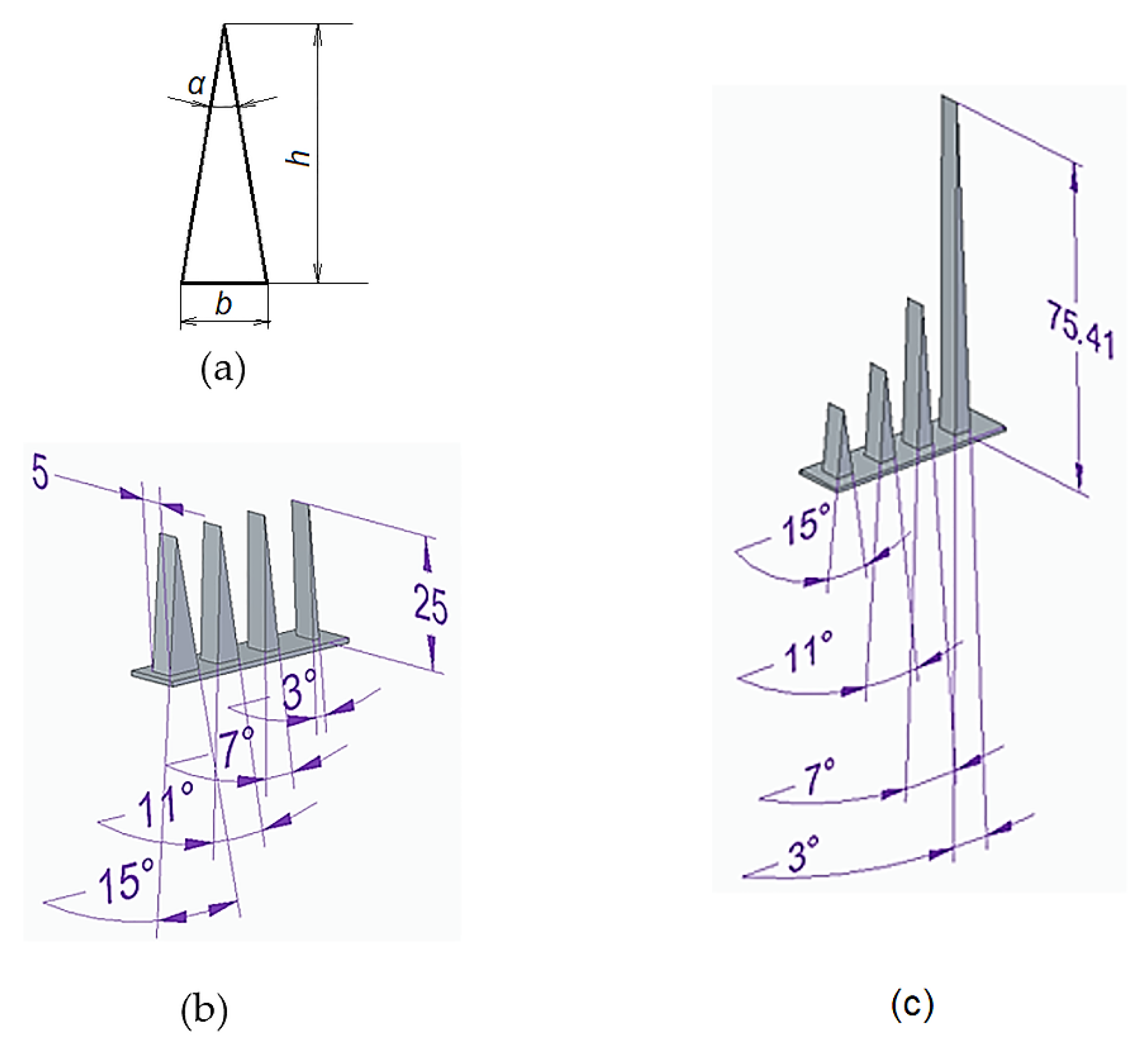
The values of certain dimensions that characterize the shape of the sample surfaces to be produced (the presence of some intersections made by small values of the intersection angles or the connection radii, the thickness of the sample, the coefficient of the slenderness of some areas of the sample, etc.);
-
Characteristics of the wire/filament generated by the printer nozzle (diameter of the deposition filament, corresponding to the diameter of the nozzle hole) and of the filament material (melting temperature, viscosity, specific heat and thermal conductivity, thermal shrinkage, the adhesion capacity between the deposited layers, etc.);
-
Elements of thermal conditions of operation of some components/subassemblies of the printer (heating temperature of the nozzle, temperature of the plate on which the deposition takes place, ventilation cooling, etc.);
-
Parameters that characterize the deposition conditions (travel speed between nozzle and printer table, the thickness of the deposited layer, etc.);
-
The degree of filling of the spaces between the walls of the sample, etc.
Experiments carried out by printer manufacturers have led to the formulation of recommendations by printer manufacturers for the values of some of the working parameters that their users could take into account.
The values of the input factors used in the 3D printing of samples consisting of triangles designed to have the same height h were included in Table 1.

3. Materials and Methods

A test sample with the shape and dimensions shown in Figure 1b was first designed to verify experimentally some of the theoretical considerations mentioned above.
The actual samples were made of polylactic acid (PLA), one of the most attractive materials for the planned experiment due to its high versatility. From the multitude of factors capable of influencing the height of isosceles triangles, in experimental research, the thickness tl of the deposited layer, printing speed v, cooling c, infill I, and the size of the isosceles vertex angle α were taken into account.
The samples were produced on an Ultimaker 2+ type of equipment (made by Ultimaker—Netherlands) with its own designated software Ultimaker Cura.
To reduce the number of experimental tests and, at the same time, to arrive at a sufficiently precise image of the influence exerted by the variation of the input factors in the printing process on the values of the output parameters, a planned factorial experiment using the Taguchi L9 method was used, with five independent variables (layer thickness, printing speed, cooling, infill, and sample thickness) at three experimental levels. An L9 orthogonal array allows the use of a minimum number of experimental trials to study the effect of 5 independent factors, each with three levels of evaluation. Such an experiment can be used when accepting the hypothesis that there is no interaction between any two factors [34].
There are many input factors of the 3D-printing process that could be considered as independent variables. From this multitude of factors, those factors were taken into account that could be assumed to have a significant influence on the values of the output parameters. Attention was also paid to the possibilities of using different values for input factors on the available 3D-printing equipment.
When establishing the initial values of the independent variables (of the input factors in the 3D-printing process), the printer manufacturer’s recommendations were taken into account first. Thus, three distinct thicknesses tl of the deposited layers were used (0.06 mm, 0.1 mm, and 0.15 mm), as well as three printing speeds v (50 mm/s, 55 mm/s, and 60 mm/s, three characterized cooling regimes c (0%, 50%, and 100%), three levels of filling (infill) i of the inner space of the sample (18%, 20%, and 22%), and three thicknesses ts of the samples (5 mm, 7.5 mm, 10 mm).
Intending to arrive at some empirical mathematical models that highlight the influence of other input factors in the 3D-printing process, apart from those initially considered by using the planned Taguchi L9 factorial experiment, blocks of 4 adjacent isosceles triangles were printed, as can be seen in Figure 2 and Figure 3 and Table 1, with vertex angles of 15°, 11°, 7°, and 3°.
Preliminary tests showed, however, that it is not possible to produce acceptable samples with a thickness below 5 mm in the same setup as the authors used. In the latter case, due to a less acceptable combination of the values of the printing parameters (values established based on the printer manufacturer’s recommendations), thin samples were found that do not interrupt when switching from one isosceles triangle to another.
The values of the input factors in the process of 3D printing the samples aimed at obtaining triangles with the same height are included in Table 1.

4. Results

According to the hypotheses initially adopted, the tests showed different heights of the four isosceles triangles with visibly different values of the vertex angles α, in the case of tests that were to lead to the same height h for all four isosceles triangles. In this way, additional information was obtained on the ability of the printing equipment to achieve precise details of the printed parts.
It was also expected that, from a practical point of view, differences in the heights of the triangles would occur when the execution of isosceles triangles with the same size of the base length was considered.
The actual heights h of the triangles were determined by measurement using a LeeXo 50-1600X digital optical microscope (China). The values of the heights of the triangles are also included in Table 1.
Examination of the facilities offered by the software used to program the printing process showed that an image of the heights of isosceles triangles achievable by 3D printing could be obtained using a reverse-engineering process applied to the G codes developed by the software for each situation. Thus, we designed the 3D prisms in a CAD environment, namely SolidEdge. We saved our samples in .stl format and imported them into the Ultimaker Cure software, where we used specific settings for each sample. After all the printing parameters were established, we sliced each sample and saved the document in a .gcode file format. These files were fed to the 3D printer, and each sample was produced. We reverse-engineered the .gcode files by importing each of them into the Voxelizer software where, specifying exactly the same layer height as the one used for each sample, we converted them to the .stl format. Each new .stl format document was imported into Ansys SpaceClaim, where we measured the height h of each sample accurately.
Thus, it was possible to highlight some aspects of the printer’s capability before the actual printing process. For a sample thickness ts = 10 mm, and for certain values of the parameters of the printing conditions, in Figure 2, the solid model of the sample, the model obtained by reverse engineering, and the real image of the printed sample can be observed. Images similar to those in Figure 2, but valid for the situation when it was proposed to obtain isosceles triangles that have the same length b of the base of the triangle and heights h determined by the value of the vertex angle α, can be seen in Figure 3.

5. Discussion

The experimental results included in Table 1 and Table 2 were mathematically processed using specialized software [35]. Thus, empirical mathematical models of the power-function type were determined. It was preferred to identify some mathematical functions such as power-type functions, considering that due to the intervals of variation of the input factor values, monotone variations of the values of the heights of the isosceles triangles will be produced from the 3D-printing process. Such mathematical models of the power-function type are also frequently used in various situations in machine manufacturing. The mathematical processing of the experimental results included in Table 1 and Table 2 with the help of specialized software was based on the least-squares method.
In the case of samples including triangles with desired constant height h, the following empirical mathematical models were obtained:
-
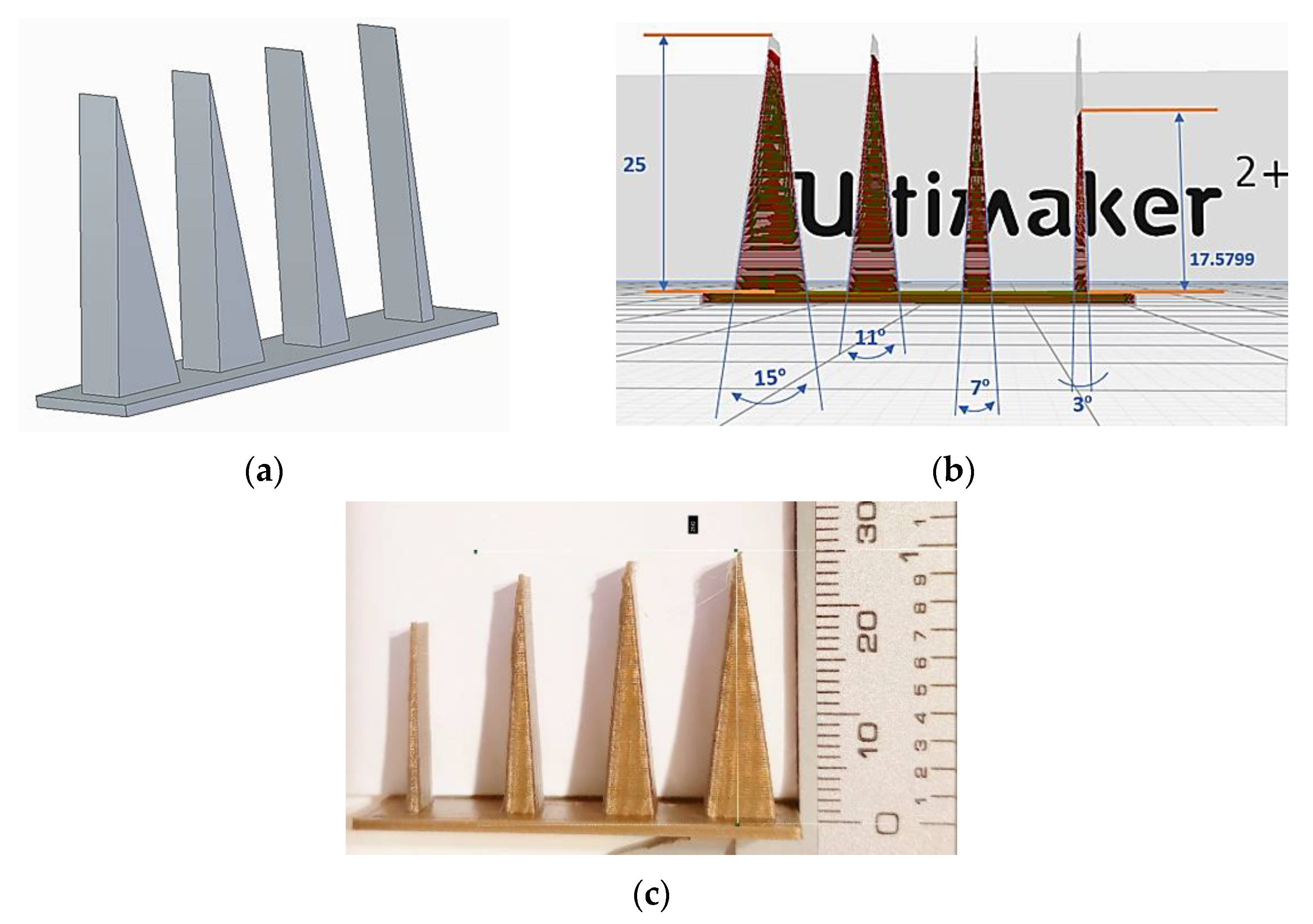
For the height determined by using G code:
h = 5.162 t l 0.00121 v 0.324 c 0.000330 i 0.0343 t s 0.0781 α 0.190
-
By using the experimental results:
h = 19.929 t l 0.000713 v 0.0860 c 0.000078 i 0.00131 t s 0.0215 α 0.190
Regarding the samples containing isosceles triangles with bases of the same length b, the following mathematical models were determined:
-
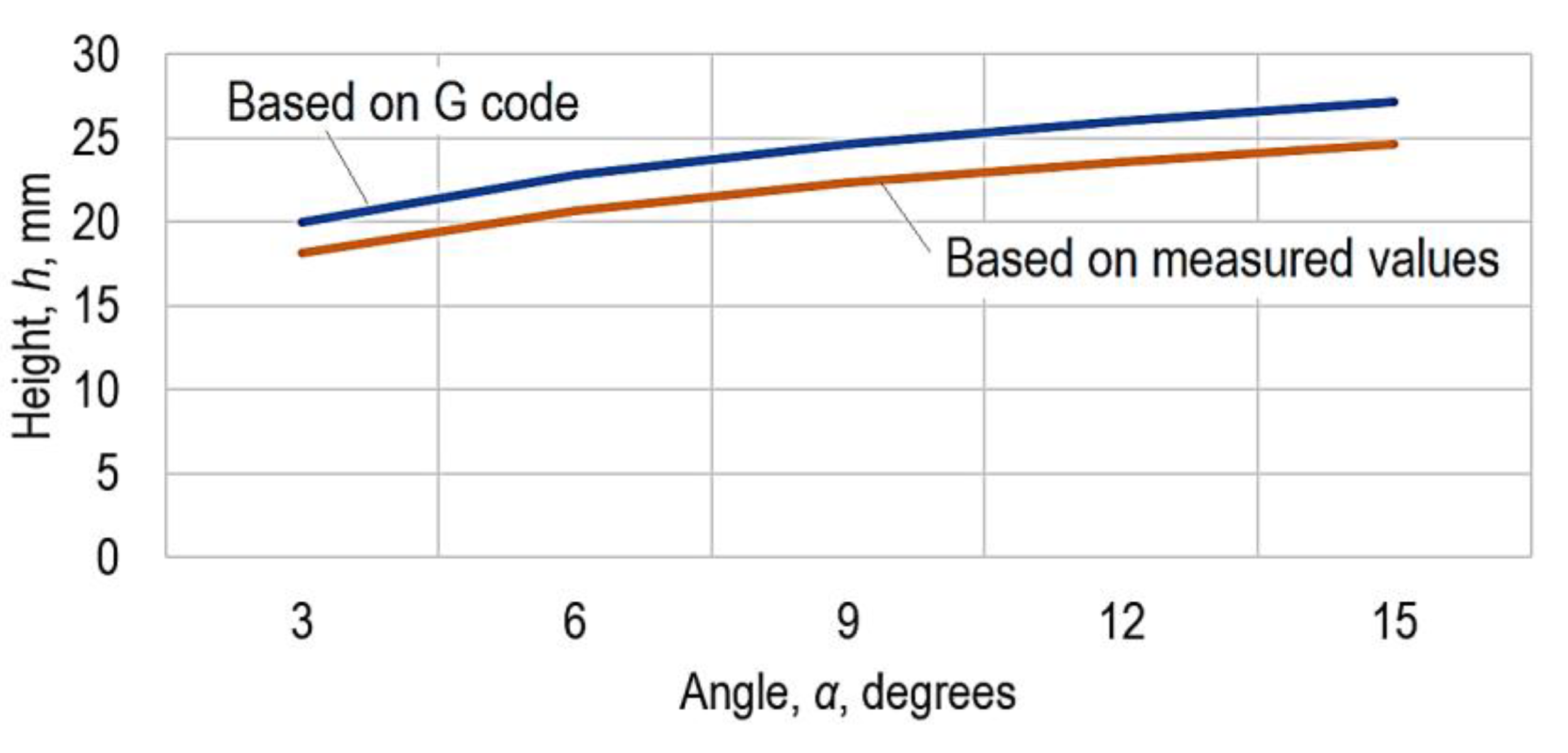
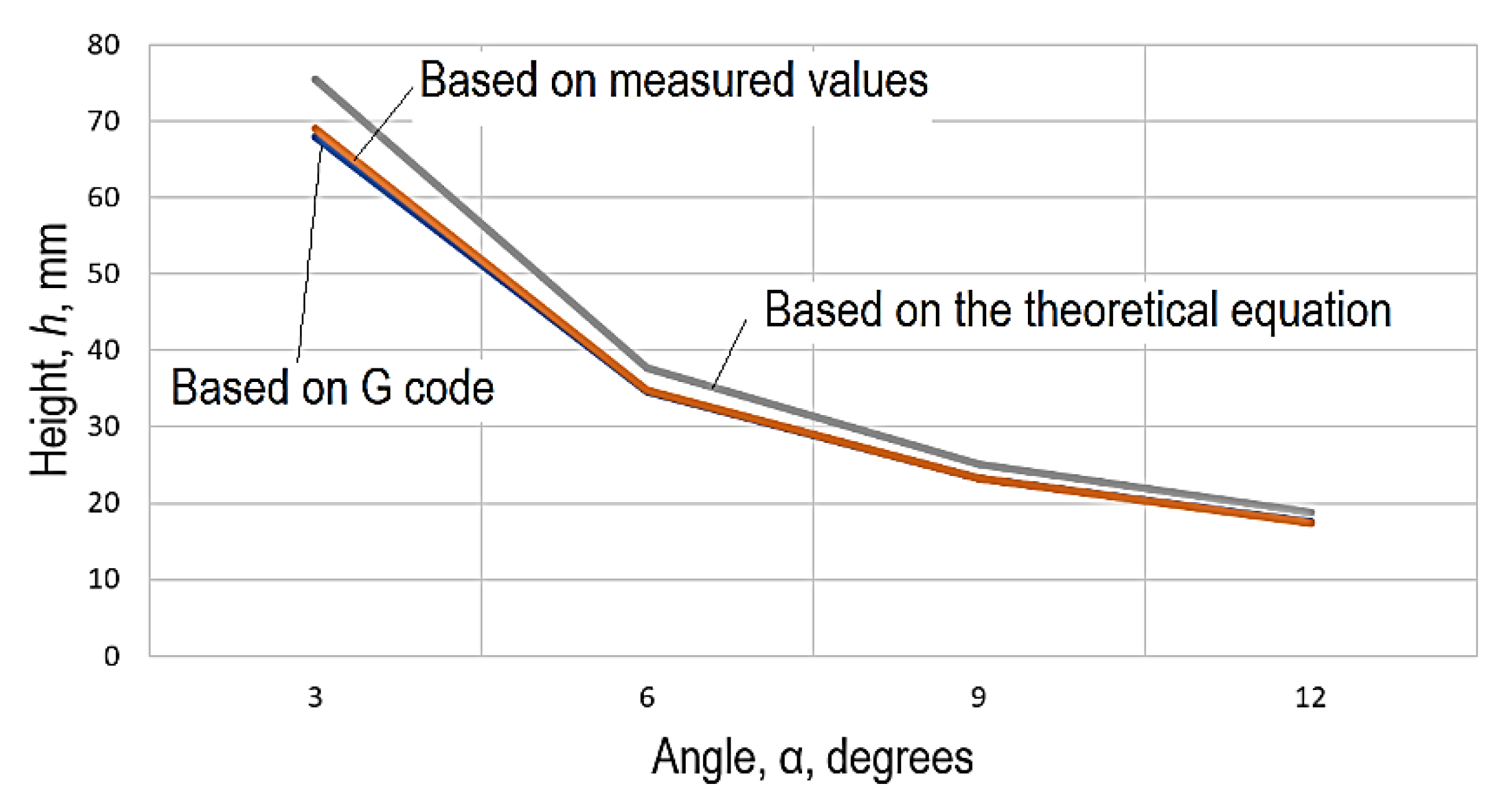
For the theoretical variation of the height h of the triangles, Equation (2) remains valid;
-
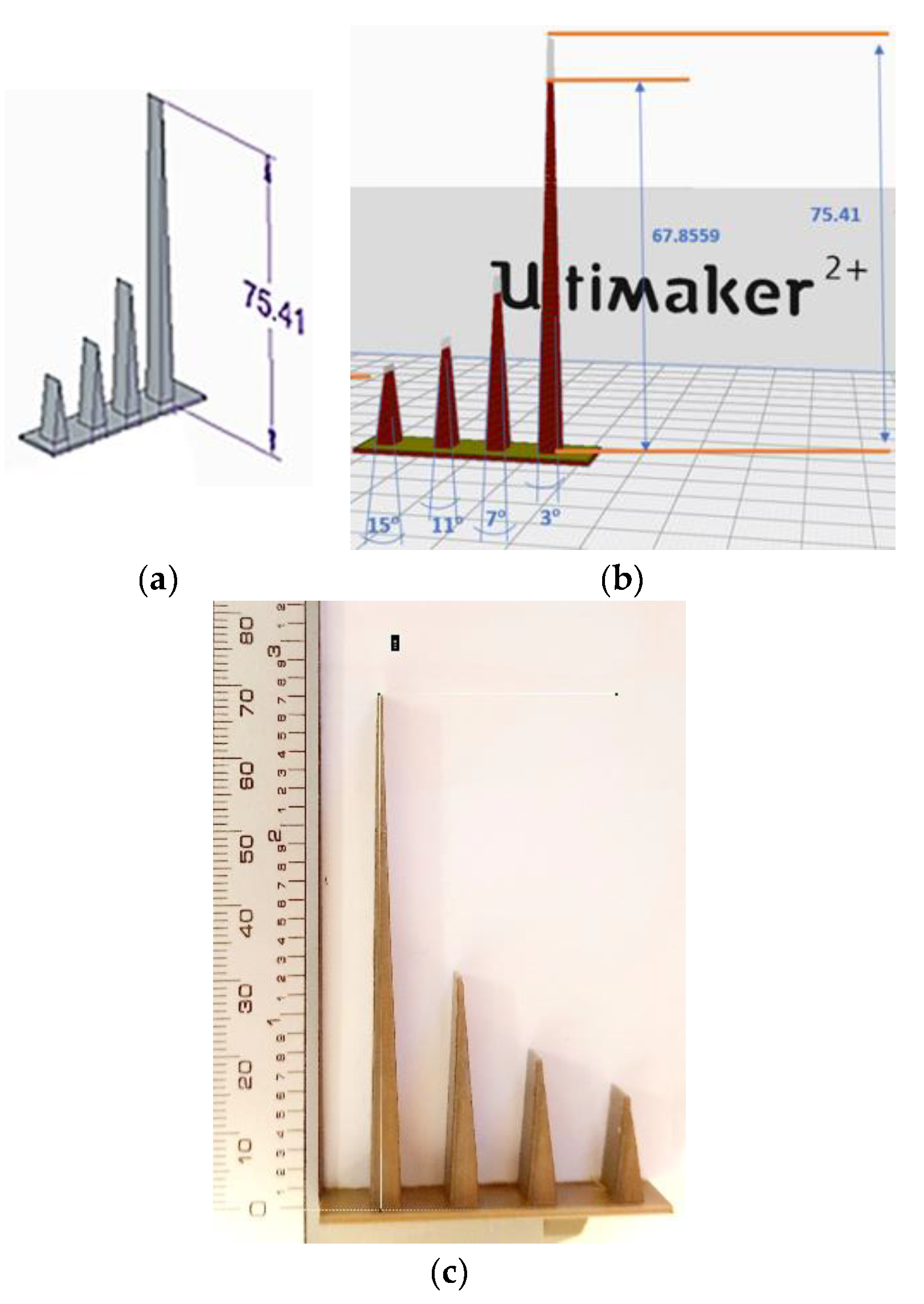
For the variation of the height h of the triangles determined by taking into account the G code:
h = 43.405 t l 0.0228 v 0.441 c 0.000645 i 0.0165 t s 0.123 α 0.975
-
By taking into account the experimental results:
h = 320.696 t l 0.00120 v 0.122 c 0.0000890 i 0.00440 t s 0.0290 α 0.992
Using the empirical mathematical models corresponding to Equations (3)–(6), the graphical representations in Figure 4 and Figure 5 were elaborated. Analysis of these graphical representations and of the empirical mathematical models constituted by Equations (3)–(6) allowed the following comments to be made.
The absolute values of the exponents attached to each of the input factors used in the 3D-printing process can be examined to reveal the intensity of the influence exerted by the factors taken into account. It is thus found that when triangles of the same height h must be obtained, the strongest influence is exerted by the size of the α angle at the vertices of the isosceles triangle, since the values of the exponents attached to the α size are much higher compared to the values of the exponents attached to the other process input factors. It can still be seen that as the size of the α angle increases, there is an increase in the height h, since the value of the exponent is positive. The other input factors taken into account exert a minimal and negligible influence on the considered output parameter.
The diagram in Figure 4 shows that the values obtained using G code are higher than those determined experimentally.
In the case of isosceles triangles that were to have the same length b of the base, increasing the value of the α angle leads to a decrease in the height h of the isosceles triangles, as shown in Equations (5) and (6). As in the previous case and as expected, the strongest influence is exerted by the size of the α angle, at the increase of which there is a decrease in the height h of the isosceles triangles. It should be noted that both mathematical models lead to identical values of the exponent attached to the size of the α angle (−0.975).
In this case, the values based on the G code are lower compared to the measured values and those corresponding to the theoretical model constituted by Equation (2). It can be seen that the values obtained using the empirical mathematical model are close enough to those determined by using the theoretical mathematical model that in the graphical representation in Figure 5, the two curves almost coincide. An explanation could consider the thermal phenomena that develop during the printing process and the material’s behavior when brought into the plastic state by melting during the 3D-printing process.
An assessment of the situation in which it is possible to obtain the lowest value Δ for the difference between the values obtained by experimental tests and the values corresponding to the theoretical model of Equation (2) can be made by following the values included in the last columns of Table 1 and Table 2. Thus, it can be found that there are several combinations of the values of the input factors in the 3D-printing process that led to the reduction of the deviation Δ from the desired values of the heights h. In the case of triangles that should have the same height h (Table 1), it is found that the combinations of values of the input factors corresponding to the experiments with numbers 4–9 ensure minimum deviation values Δ. For triangles that had to have the same length b of the base (Table 2), the input factors corresponding to the experimental tests with numbers 4–9 lead to minimal deviations.

6. Conclusions

The problem of producing fine detail by 3D-printing processes continues to be a concern for researchers involved in the investigation and use of such processes. Complete factorial experiments were designed and materialized based on the initial use of Taguchi L9 factorial experiments, with five independent variables at three experimental levels. Additionally, four values of the intersection angles of the flat surfaces corresponding to prismatic surfaces with cross-sections in the form of isosceles triangles were taken into account. In this way, the input factors considered were the thickness of the deposited layer, the printing speed, the degree of cooling, the infill level, the thickness of the sample, and the size of the intersection angle of the flat surfaces, respectively.
The experimental tests first aimed at obtaining isosceles triangles with the same height but with different values of the vertex angle. Subsequently, other triangles characterized by the same value of the base length and by distinct values of the vertex angle were considered. The mathematical processing using specialized software led to obtaining some empirical mathematical models of the power-function type.
The analysis of these mathematical models showed that the factors with the strongest influence on the deviations from the theoretically designed heights of the triangles were the value of the vertex angle of the isosceles triangle and the printing speed, respectively. The analysis of the differences between the theoretical values of the heights of isosceles triangles and the values of these heights determined experimentally highlighted the existence of some combinations of the values of the input factors for which the deviations are minimal. In the future, the intent is to continue experimental research by considering the influence of other input factors in the 3D-printing process, one of these factors being the nature of the material used for deposition.

Author Contributions

Conceptualization, L.S.; Data curation, A.M.M. and G.N.; Formal analysis, A.M.M. and A.H.; Investigation, A.M.M.; Methodology, A.H. and O.D.; Project administration, L.S.; Resources, G.N.; Validation, A.M.; Visualization, O.D.; Writing—original draft, L.S.; Writing—review & editing, A.M.M. and A.H. All authors have read and agreed to the published version of the manuscript.

Funding

This research received no external funding.

Institutional Review Board Statement

Not applicable.

Informed Consent Statement

Not applicable.

Conflicts of Interest

The authors declare no conflict of interest.

References

  1. Brischetto, S.; Maggiore, P.; Ferro, C.G. (Eds.) Additive Manufacturing Technologies and Applications; MDPI: Basel, Switzerland, 2017; pp. 1–180. [Google Scholar] [CrossRef] [Green Version]
  2. Ponis, S.; Aretoulaki, E.; Maroutas, T.N.; Plakas, G.; Dimogiorgi, K. A systematic literature review on additive manufacturing in the context of circular economy. Sustainability 2021, 13, 6007. [Google Scholar] [CrossRef]
  3. Mehrpouya, M.; Dehghanghadikolaei, A.; Fotovvati, B.; Vosooghnia, A.; Emamian, S.S.; Gisario, A. The potential of additive manufacturing in the smart factory industrial 4.0: A review. Appl. Sci. 2019, 9, 3865. [Google Scholar] [CrossRef] [Green Version]
  4. Asnaf, N. Metal Additive Manufacturing—State of the Art 2020. Metals 2021, 11, 867. [Google Scholar] [CrossRef]
  5. Arefin, A.M.E.; Khatri, N.R.; Kulkarni, N.; Egan, P.F. Polymer 3D Printing Review: Materials, Process, and Design Strategies for Medical Applications. Polymers 2021, 13, 1499. [Google Scholar] [CrossRef]
  6. Azad, M.A.; Olawuni, D.; Kimbell, G.; Badruddoza, A.Z.M.; Hossain, M.S.; Sultana, T. Polymers for extrusion-based 3D printing of pharmaceuticals: A holistic materials–process perspective. Pharmaceutics 2020, 12, 124. [Google Scholar] [CrossRef] [Green Version]
  7. Bagalkot, A.; Pons, D.; Symons, D.; Clucas, D. Analysis of raised feature failures on 3D printed injection moulds. Polymers 2021, 13, 1541. [Google Scholar] [CrossRef] [PubMed]
  8. Gwamuri, J.; Franco, D.; Khan, K.Y.; Gauchia, L.; Pearce, J.M. High-efficiency solar-powered 3-D printers for sustainable development. Machines 2016, 4, 3. [Google Scholar] [CrossRef]
  9. Mantelli, A.; Romani, A.; Suriano, R.; Diani, M.; Colledani, M.; Sarlin, E.; Turri, S.; Levi, M. UV-Assisted 3D printing of polymer composites from thermally and mechanically recycled carbon fibers. Polymers 2021, 13, 726. [Google Scholar] [CrossRef] [PubMed]
  10. Nath, S.D.; Nilufar, S. An Overview of Additive Manufacturing of Polymers and Associated Composites. Polymers 2020, 12, 2719. [Google Scholar] [CrossRef] [PubMed]
  11. Ziółkowski, M.; Dyl, T. Possible Applications of Additive Manufacturing Technologies in Shipbuilding: A Review. Machines 2020, 8, 84. [Google Scholar] [CrossRef]
  12. Amza, C.G.; Zapciu, A.; Constantin, G.; Baciu, F.; Vasile, M.I. Enhancing mechanical properties of polymer 3D printed parts. Polymers 2021, 13, 562. [Google Scholar] [CrossRef] [PubMed]
  13. Avdeev, A.; Shvets, A.; Gushchin, I.; Torubarov, I.; Drobotov, A.; Makarov, A.; Plotnikov, A.; Serdobintsev, Y. Strength increasing additive manufacturing fused filament fabrication technology, based on spiral toolpath material deposition. Machines 2019, 7, 57. [Google Scholar] [CrossRef] [Green Version]
  14. Calignano, F.; Lorusso, M.; Roppolo, I.; Minetola, P. Investigation of the Mechanical Properties of a Carbon Fibre-Reinforced Nylon Filament for 3D Printing. Machines 2020, 8, 52. [Google Scholar] [CrossRef]
  15. Ferrari, F.; Corcione, C.E.; Montagna, F.; Maffezzoli, A. 3D printing of polymerwaste for improving people’s awareness about marine litter. Polymers 2020, 12, 1738. [Google Scholar] [CrossRef]
  16. Mazzanti, V.; Malagutti, L.; Mollica, F. FDM 3D printing of polymers containing natural fillers: A review of their mechanical properties. Polymers 2019, 11, 1094. [Google Scholar] [CrossRef] [Green Version]
  17. Pezzana, L.; Riccucci, G.; Spriano, S.; Battegazzore, D.; Sangermano, M.; Chiappone, A. 3D printing of PDMS-like polymer nanocomposites with enhanced thermal conductivity: Boron nitride based photocuring system. Nanomaterials 2021, 11, 373. [Google Scholar] [CrossRef]
  18. Ritzen, L.; Montano, V.; Garcia, S.J. 3D printing of a self-healing thermoplastic polyurethane through fdm: From polymer slab to mechanical assessment. Polymers 2021, 13, 305. [Google Scholar] [CrossRef]
  19. Wickramasinghe, S.; Do, T.; Tran, P. FDM-based 3D printing of polymer and associated composite: A review on mechanical properties, defects and treatments. Polymers 2020, 12, 1529. [Google Scholar] [CrossRef] [PubMed]
  20. Jones, A.; Straub, J. Concepts for 3D printing-based self-replicating robot command and coordination techniques. Machines 2017, 5, 12. [Google Scholar] [CrossRef] [Green Version]
  21. Straub, J. Initial Work on the Characterization of Additive Manufacturing (3D Printing) Using Software Image Analysis. Machines 2015, 3, 55–71. [Google Scholar] [CrossRef] [Green Version]
  22. Msallem, B.; Sharma, N.; Cao, S.; Halbeisen, F.S.; Zeilhofer, H.F.; Thieringer, F.M. Evaluation of the dimensional accuracy of 3d-printed anatomical mandibular models using FFF, SLA, SLS, MJ, and BJ printing technology. J. Clin. Med. 2020, 9, 817. [Google Scholar] [CrossRef] [Green Version]
  23. Yoo, S.-Y.; Kim, S.-K.; Heo, S.-J.; Koak, J.-Y.; Kim, J.-G. Dimensional accuracy of dental models for three-unit prostheses fabricated by various 3d printing technologies. Materials 2021, 14, 1550. [Google Scholar] [CrossRef]
  24. Dorweiler, B.; Baqué, P.E.; Chaban, R.; Ghazy, A.; Salem, O. Quality control in 3D printing: Accuracy analysis of 3D-printed models of patient-specific anatomy. Materials 2021, 14, 1021. [Google Scholar] [CrossRef]
  25. Lee, S.; Squelch, A.; Sunm, Z. Quantitative assessment of 3D printed model accuracy in delineating congenital heart disease. Biomolecules 2021, 11, 270. [Google Scholar] [CrossRef]
  26. Czajkowska, M.; Walejewska, E.; Zadrozny, Ł.; Wieczorek, M.; Swieszkowski, W.; Wagner, L.; Mijiritsky, E.; Markowski, J. Comparison of dental stone models and their 3D printed acrylic replicas for the accuracy and mechanical properties. Materials 2020, 13, 4066. [Google Scholar] [CrossRef] [PubMed]
  27. Budzik, G.; Wozniak, J.; Paszkiewicz, A.; Przeszłowski, Ł.; Dziubek, T.; Debski, M. Methodology for the quality control process of additive manufacturing products made of polymer materials. Materials 2021, 14, 2202. [Google Scholar] [CrossRef]
  28. Slătineanu, L.; Dodun, O.; Nagit, G.; Coteață, M.; Bosoancă, G.; Beșliu, I. Fine details obtained by 3D printing and using polymers. Mater. Plast. 2018, 55, 474–477. [Google Scholar] [CrossRef]
  29. Boca, M.-A.; Sover, A.; Slătineanu, L. The dimensional accuracy of the test parts made of various plastic materials by the fused filament fabrication process. IOP Conf. Ser. Mater. Sci. Eng. 2020, 997, 012021. [Google Scholar] [CrossRef]
  30. Kaschwich, M.; Horn, M.; Matthiensen, S.; Stahlberg, E.; Behrendt, C.A.; Matysiak, F.; Bouchagiar, J.; Dell, A.; Ellebrecht, D.; Bayer, A.; et al. Accuracy evaluation of patient-specific 3D-printed aortic anatomy. Ann. Anat. 2021, 234. [Google Scholar] [CrossRef]
  31. Sun, Y.; Ding, Q.; Tang, L.; Zhang, L.; Sun, Y.; Xie, Q. Accuracy of a chairside fused deposition modeling 3D-printed single-tooth surgical template for implant placement: An in vitro comparison with a light cured template. J. Cranio Maxillofac. Surg. 2019, 47, 1216–1221. [Google Scholar] [CrossRef]
  32. Herpel, C.; Tasaka, A.; Higuchi, S.; Finke, D.; Kühle, R.; Odaka, K.; Rues, S.; Lux, C.-J.; Yamashita, S.; Rammelsberg, P.; et al. Accuracy of 3D printing compared with milling—A multi-center analysis of try-in dentures. J. Dent. 2021, 110, 103681. [Google Scholar] [CrossRef] [PubMed]
  33. Wu, H.; Fan, G. An overview of tailoring strain delocalization for strength-ductility synergy. Prog. Mater. Sci. 2020, 113, 100675. [Google Scholar] [CrossRef]
  34. Chapter 2 Introduction to Taguchi Method. University of Massachusetts Amherst. Available online: http://www.ecs.umass.edu/mie/labs/mda/fea/sankar/chap2.html (accessed on 16 July 2021).
  35. Crețu, G. Fundamentals of Experimental Research; “Gheorghe Asachi” Technical University of Iasi: Iasi, Romania, 1992. (In Romanian) [Google Scholar]
Figure 1. Considered dimensions of the triangle (a) and a sample consisting of triangles: (b) that have the same height h; (c) that have the same length l of the base.
Machines 09 00150 g001
Figure 2. Images of the designed sample (a), the sample produced using reverse engineering and G code (b), and the real sample (c) (work conditions: tl = 0.06 mm, v = 60 mm/s, cool = 100%, I = 18%, ts = 10 mm), in case of the need to obtain triangles of the same height h, but with different values of the vertex angle α.
Machines 09 00150 g002
Figure 3. Images of the designed sample (a), of the sample, produced using the inverse engineering and G code (b), and of the real sample (c) (work conditions: tl = 0.06 mm, v = 60 mm/s, c = 100%, I = 18%, ts = 10 mm), in case of the need to obtain triangles with the same length b of the base for different values of the vertex angle α.
Machines 09 00150 g003
Figure 4. The influence exerted by the size of the angle α on the height h of the isosceles triangle, when the intent was to obtain triangles with the same height h (tl = 0.1 mm, v = 55 mm/s, c = 55%, I = 20, ts = 7.5 mm; the blue line corresponds to the mathematical model established by using G code; the red line corresponds to the mathematical model determined by taking into account the measured values).
Machines 09 00150 g004
Figure 5. The influence exerted by the size of the angle α on the height h of the isosceles triangle, when the intent was to obtain triangles with the same length b of the base (tl = 0.1 mm, v = 55 mm/s, c = 50%, I = 20%, ts = 7.5 mm; the blue line corresponds to the mathematical model established by using G code; the red line corresponds to the mathematical model determined by taking into account the measured values; the grey line corresponds to the theoretical model constituted by the Equation (1)).
Machines 09 00150 g005
Table 1. Experimental conditions and results in 3D printing of samples consisting of triangles designed to have the same height h.
Exp.
No.
Values of the Input FactorsAchievable Height h of the Triangle, mm, by Considering G Code/Real Height of the Triangle, mm, for Vertex Angle α, o, of:Deviation, Δ, mm
Deposited Layer Thickness tl, mmPrinting Speed v, mm/sCooling c, %Infill i, %Sample Thickness ts, mm151173
10.0650022523.9343/
23.8
23.2522/
23.4
21.9121/
22.2
17.3723/
17.8
0.7568
20.065550207.523.8254/
24
23.1613/
23.5
22.0139/
22.1
17.5799/
17.8
0.5568
30.0660100181023.815/
23.9
23.4581/
23.4
22.1120/
22.2
18.4442/
17.8
0.6568
40.1505018523.8652/
24
23.2738/
23.4
22.5883/
22.2
17.9017/
17.7
0.5568
50.155100227.523.8883/
24
23.4691/
23.4
22.0833/
22.2
17.6337/
17.7
0.5568
60.1600201023.8816/
23.9
23.4008/
23.4
21.9920/
22.2
17.6675/
17.7
0.6568
70.155010020523.8882/
24
23.3956/
23.4
21.9474/
22.3
17.4919/
17.7
0.5568
80.15550187.523.8784/
23.9
23.1641/
23.4
22.2486/
22.2
17.5280/
17.7
0.6568
90.156050221023.8670/
23.9
23.4079/
23.4
22.1936/
22.1
17.7187/
17.8
0.6568
Table 2. Experimental conditions and results in 3D printing of samples consisting of isosceles triangles designed to have the same length b of the base.
Exp.
No.
Values of the Input FactorsIntended Height of the Triangle, mm, by Considering the G Code/Real Height of the Triangle, mm, for Vertex Angle α, °, of:Deviation Δ, mm
Deposited Layer Thickness tl, mmPrinting Speed v, mm/sCoo-
ling c, %
Infill i, %Sample Thickness,
ts, mm
151173
10.0650022513.9293/
13.8
18.7728/
18.8
29.1808/
29.5
67.8049/
71
0.9416
20.065550207.513.8192/
13.9
19.2261/
19
29.2671/
29.6
67.8508/
68.5
0.8416
30.0660100181013.9112/
13.9
18.9852/
19.1
29.4398/
29.5
67.8559/
68.4
0.8416
40.10505018513.8178/
14
19.7232/
19
29.9709/
29.6
68.1037/
68.8
0.7416
50.1055100227.513.8361/
14
18.7852/
18.9
29.4599/
29.5
68.246/
68.5
0.7416
60.10600201013.8679/
14
19.125/
18.8
30.0142/
29.6
68.0931/
68.5
0.7416
70.155010020513.9187/
14
20.1006/
19
29.5744/
29.5
67.8714/
68.5
0.7416
80.15550187.513.919/
14
19.161/
19
29.6599/
29.5
68.0868/
69.4
0.7416
90.156050221014.3825/
14
19.4766/
19
30.1188/
29.5
68.0014/
68.8
0.7416
Theoretical height h of the isosceles triangle, mm, taking into account a base length b = 3.95 mm and distinct values of the vertex angle α14.741620.320932.170175.3704
Publisher’s Note: MDPI stays neutral with regard to jurisdictional claims in published maps and institutional affiliations.

