Article

Finding the Best Programmable PWM Pattern for Three-Level Active Front-Ends at 18-Pulse Connection

Department of Mechatronics and Automation, South Ural State University, 454080 Chelyabinsk, Russia
*
Author to whom correspondence should be addressed.
Machines 2021, 9(7), 127; https://doi.org/10.3390/machines9070127
Submission received: 26 May 2021 / Revised: 22 June 2021 / Accepted: 22 June 2021 / Published: 23 June 2021

Abstract

:
The existing publications on the analysis of power quality indicators in modern electric power supply systems are void of a comprehensive approach to improving these indicators in power systems by implementing multipulse connections. To the authors’ knowledge, this paper is the first to analyze current harmonic distortions in an 18-pulse connection of three-level active front-ends (AFE) featuring a programmed PWM. Raw data were obtained from, and current quality was analyzed for the power circuit of the main electric drive actuating the rolls in the rolling stand of a plate mill. The key feature of such circuitry is that the synchronous motor of each work roll is connected to the grid with an 18-pulse connection that uses three phase-shift transformers, where the phase shifts are 0° (delta/delta), 20° (delta/polygon) and −20° (delta/polygon). The circuitry connects three frequency converters (FC) with the AFEs in parallel. Phase-shift transformers were found to periodically overheat in the process. When overheating occurred, a programmed PWM voltage waveform was applied where harmonics 17 and 19 were eliminated. The goal and objectives were to analyze why the transformer would overheat and to find out how the issue could be addressed. The authors developed a simulation model of the research object in order to assess power quality parameters. Simulation results obtained in Matlab/Simulink were used to estimate the total harmonic distortions (THD) and individual harmonic factors for up to the 50th secondary transformer winding and grid harmonic with four different programmed AFE PWM voltage waveforms. The results helped find the best such waveform to prevent phase-shift transformers from overheating; one with harmonics 5, 7, 17 and 19 eliminated. The experimental and mathematical modeling results in the paper were confirmed by positive effects after industrial implementation of the system. Research performed directly on the operating equipment has been classified by the company and is not publicly available. These results are highly versatile and could be used in similar research on other circuitries to ensure the electromagnetic compatibility of nonlinear power-consuming devices.

1. Introduction

Major industrial facilities nowadays commonly use multipulse connection to the grid to power up regenerative medium-voltage (MV) adjustable speed drives (ASD) [1]. Multipulse connections are a simple and effective way to reduce the effects of semiconductor power converters on the quality of grid voltage [2]. Compared to connections that use six pulses, multipulse connections have two core advantages:
  • lower total harmonic distortion (THD) [3];
  • lower individual harmonic factors for some voltage and current harmonics [4].
In turn, frequency converters (FCs) in the regenerative MV drives contain three-level active front-ends (AFE) and three-level inverters that are capable of:
  • recovering electricity to the grid when braking;
  • maintaining zero shift of the fundamental current harmonic with respect to the input voltage;
  • compensating for the reactive power at the grid connection point;
  • using programmed PWMs in order to comply with the low and medium-frequency voltage and current quality standards [5].
Despite being common and having been researched intensively from electromagnetic compatibility requirements, AFEs remain an issue in terms of their effect on the quality of grid voltage. Literature reviews suggests the following technical solutions are relevant today [6,7]:
  • using multipulse connection to the grid based on multiwinding phase-shift transformers [8];
  • use of programmed PWM voltage waveforms to eliminate or mitigate selected harmonics, i.e., Selective Harmonic Elimination PWM and Selective Harmonic Mitigation PWM [9];
  • use of passive L and LCL filters to filter out higher harmonics on the AFE AC side [10];
  • connecting MV regenerative ASD to a separate substation.

2. Statement of Problem, Goals and Objectives

A literature review helped formulate the key problem covered herein; which pertains to the development of an optimal PWM algorithm for high-power AFEs based on the NPC topology. Research of indicators contributing to the output voltage and current harmonics of AFE is associated with studying PWM control of AFEs. However, the existing publications on the analysis of power quality indicators in modern electric power supply systems are void of a comprehensive approach to improving these indicators in power systems by implementing multipulse connections.
Industrial use of the existing regenerative drives based on multipulse connections shows that stepdown phase-shift transformers tend to overheat. This issue has been reported for the 18-pulse main drive of the rolling stand of a plate mill. Preliminary analysis indicated the issue was mainly attributable to the AFEs. When overheating occurred, a programmed PWM voltage waveform was applied where harmonics 17 and 19 were eliminated. Overview of the earlier tested 18-pulse AFE-based grid connections revealed lack of an in-depth analysis into the issue.
This gave rise to the goal of this research, i.e., to analyze harmonic distortions of currents in an 18-pulse connection of three-level AFEs featuring various programmed PWM AC voltage waveforms. Raw data were obtained from, and current quality was analyzed for, the power circuit of the main electric drive actuating the rolls in the rolling stand of a plate mill; it therefore served as the object of this research. To that end, the research team developed a simulation model of this object using transfer functions and structural modeling in Matlab/Simulink. The analysis produced the best recommendable programmed PWM voltage waveform for AFEs to prevent phase-shift transformers from overheating.
The paper is structured as follows: Section 1 for introduction and relevance; Section 2 for statement of problem, goals, and objectives; Section 3 for description of the object; Section 4 for description of the control system; Section 5 for simulation results and discussion; Section 6 for conclusions.

3. Object of Research

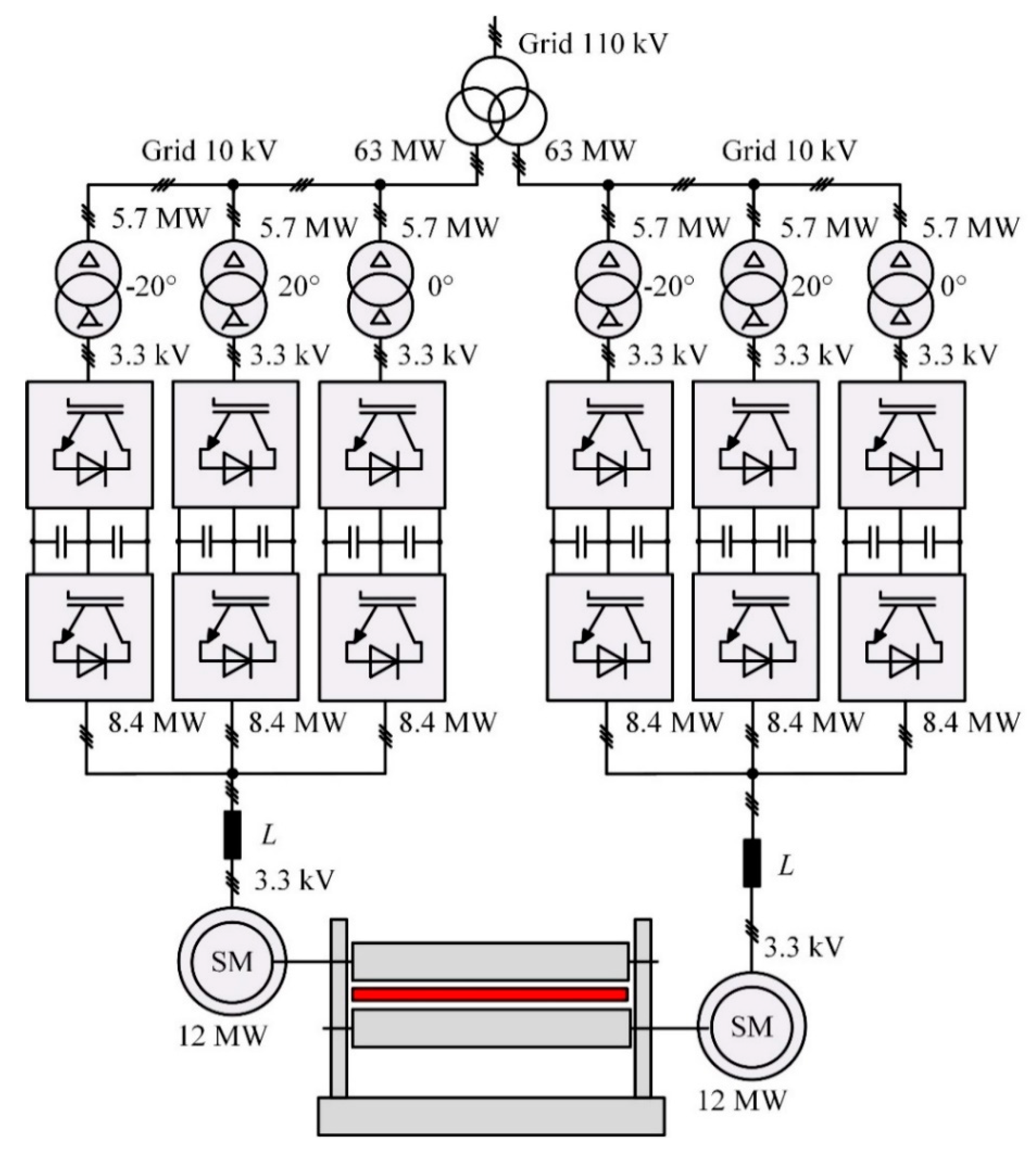
3.1. Specifications of the Object

Research was carried out on the main electric drive of the rolling stand of a plate mill. Figure 1 shows the key components of its grid connection. Table 1 shows the motor specifications. Each motor is controlled by three FCs connected in parallel to three-level AFEs, see Figure 1. Table 2 shows the AFE specifications.
The key feature of such circuitry shown in Figure 1 is that FCs are connected to the grid by an 18-pulse connection that uses three phase-shift transformers where the phase shifts are 0° (delta/delta), +20° (delta/polygon) и −20° (delta/polygon). The transformers have identical parameters, see Table 3.

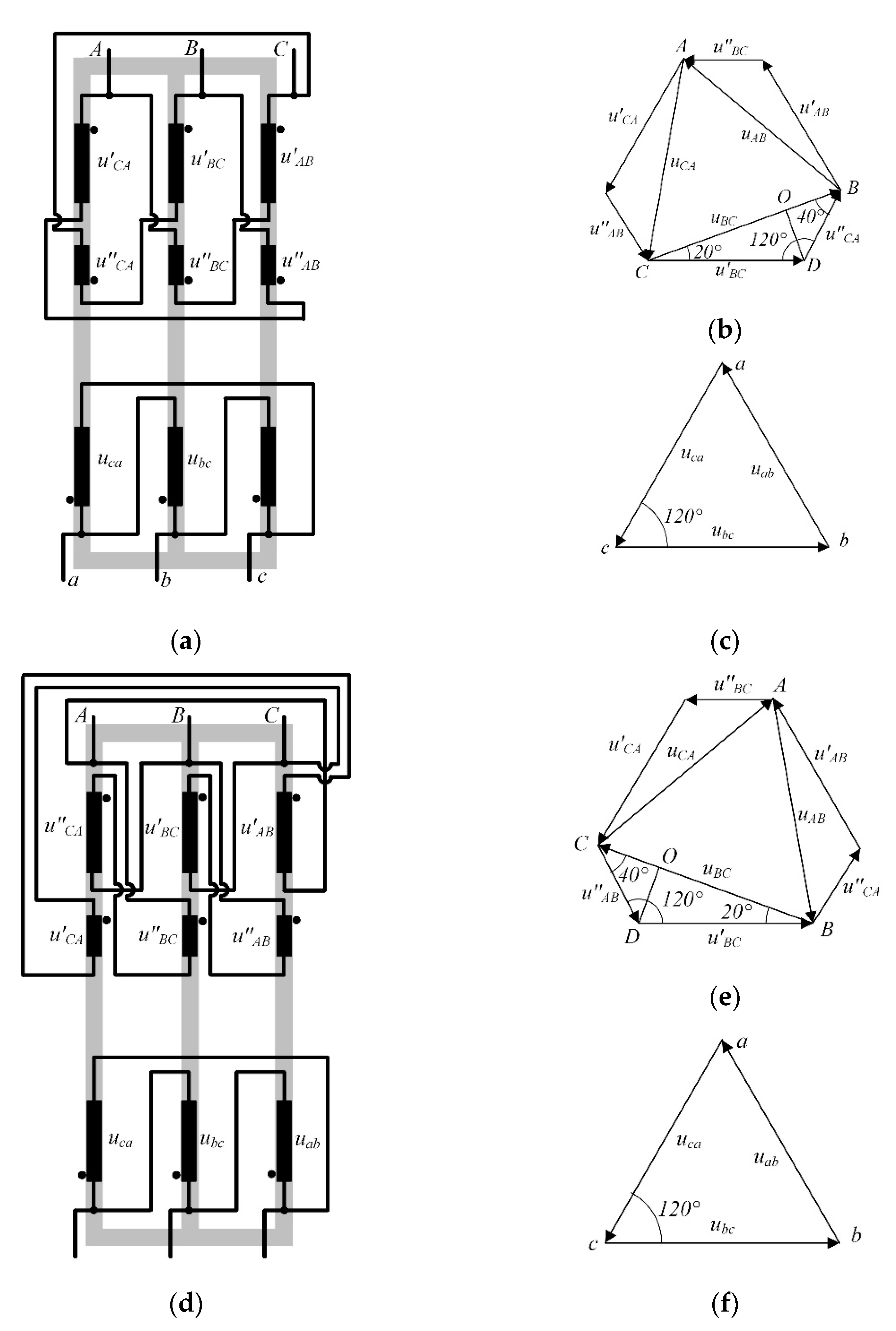
3.2. 18-Pulse Connection

Multipulse technology is a solution that provides greater total power and addresses the electromagnetic compatibility issues of nonlinear power-consuming equipment. The 18-pulse connection of the analyzed object only has the 18n ± 1 (n = 1, 2, …, ∞) significant current harmonics. This is attained by shifting the first harmonics of secondary voltages in phase-shift transformers by 0° and ±20° [11].
A +20° shift in primary voltage vectors against secondary voltage vectors in first harmonics is attained by splitting the primary winding into two sections and connecting these windings in such a way that the magnetic fluxes of this phase and of the adjacent phase are counter-directed, as shown in Figure 2a. Such connection causes the vectors to sum up and make a +20° shift against the voltage vector of the greater section. Ratios between the primary winding parts are calculated using primary voltage vector diagrams, see Figure 2b,c,e,f).
In a +20° vector shift, ratios of winding parts can be found as follows [12]: vector length U′AB, U′BC, U′CA equals 1 p.u. The angle between the vectors U′BC and –U″CA equals that between the line ac and the vector UBC (Figure 2c), which is 120°. Then, the angle DBO equals 40°. Now let us draw the perpendicular line DO to the segment BC and analyze resultant triangle DOC:
DO = DC∙sin(20°) = 1∙0.342 = 0.342 p.u.,
OC = DC∙cos(20°) = 1∙0.9397 = 0.9397 p.u.
For the triangle BDO:
BD = DO/sin(40°) = 0.342/0.6458 = 0.5321 p.u.,
BO = DO/tg(40°) = 0.342/0.839 = 0.4076 p.u.,
then
BC = OC + BO = 0.9397 + 0.4076 = 1.3473 p.u.
Thus, the total length of the secondary transformer winding equals
1 + 0.5321 = 1.5321 p.u.
In the case of a −20° vector shift (Figure 2d), the ratio between primary transformer winding parts remains the same; this shift is attained by altering the primary winding connection points.
Thus, the winding ratio is 65% of the turns in the greater part and 35% of the turns in the lesser part.

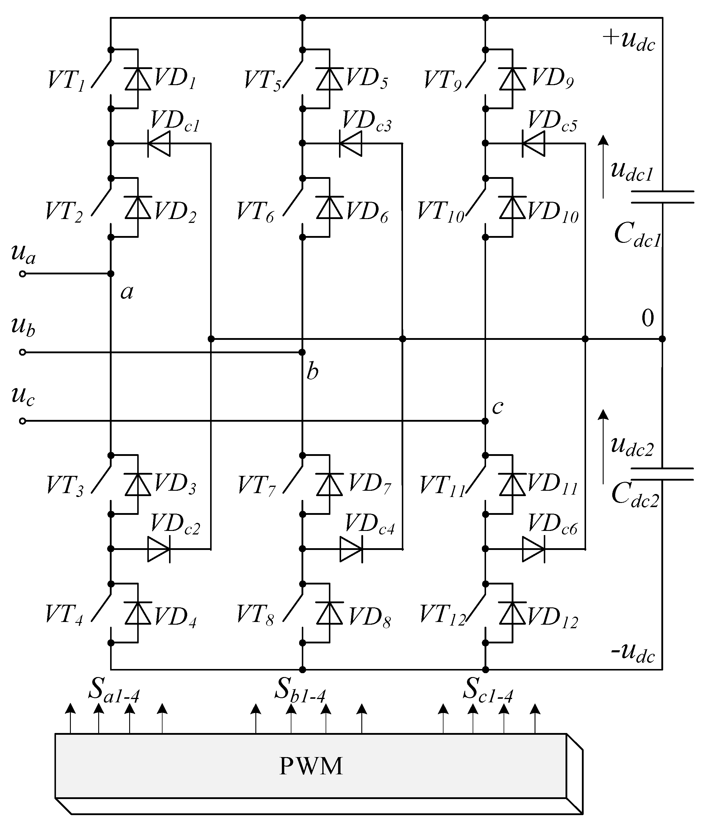
3.3. Three-Level Active Front-End

Active front-ends (AFE) are integral to high-power regenerative electric drives. AFEs have several names commonly used in the literature: PWM boost rectifiers, voltage source rectifiers (VSR), grid inverters/converters, regenerative rectifiers, and bidirectional converters. Researchers and engineers across the world continue to improve AFEs. The motivation here is that for state-of-the-art power converters, AFEs represent the most effective way to manage high power flows. AFEs coupled with multilevel converter topologies and advanced microprocessor-based control systems offer the best quality and efficiency of electric power conversion. Below are the major factors of AFE popularity:
  • bidirectional electric power flow control with configurable cos(φ) values;
  • compliance with international electromagnetic compatibility standards [13];
  • high efficiency rating at 95% to 98% [14].
Figure 3 shows a three-level AFE based on a neutral point clamped (NPC) converter topology [15]. The topology is based on a three-phase bridge that contains 12 fully controllable semiconductor switches VT1–VT12, 12 flyback diodes VD1–VD12, 6 clamped diodes VD1c–VD6c and two full capacitances Сdc1 and Сdc2. The total of udc1 and udc2 determines the DC link voltage udc. Only two of the four switches in each bridge leg can be ‘on’ at a time; they connect the potentials udc1 and udc2 to the load phase. The switching order depends on the modulation algorithm (signals Sa1–4, Sb1–4 and Sc1–4), which further determines the three-phase AFE PWM voltage waveform (ua, ub and uc). Mathematical description of three-phase AFEs follows well-known methodology and will not be covered herein.

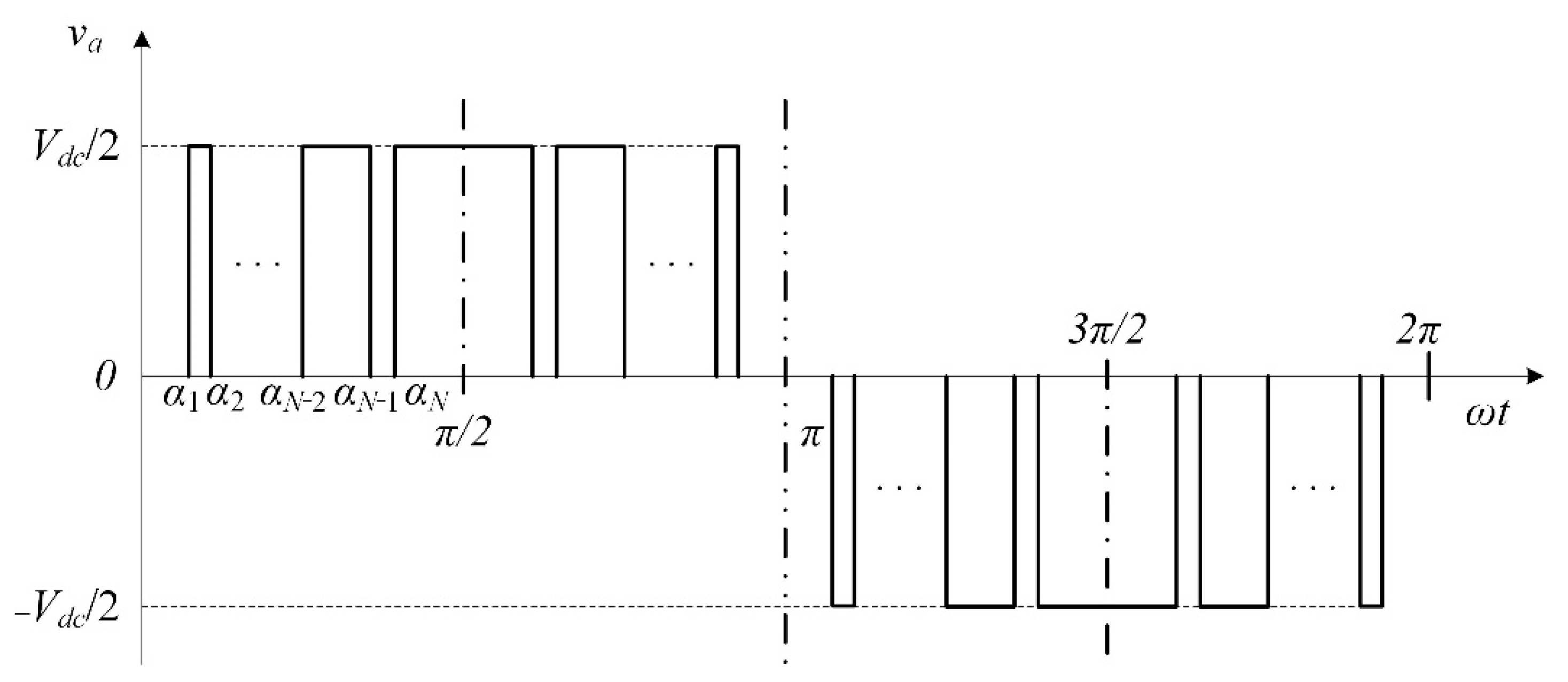
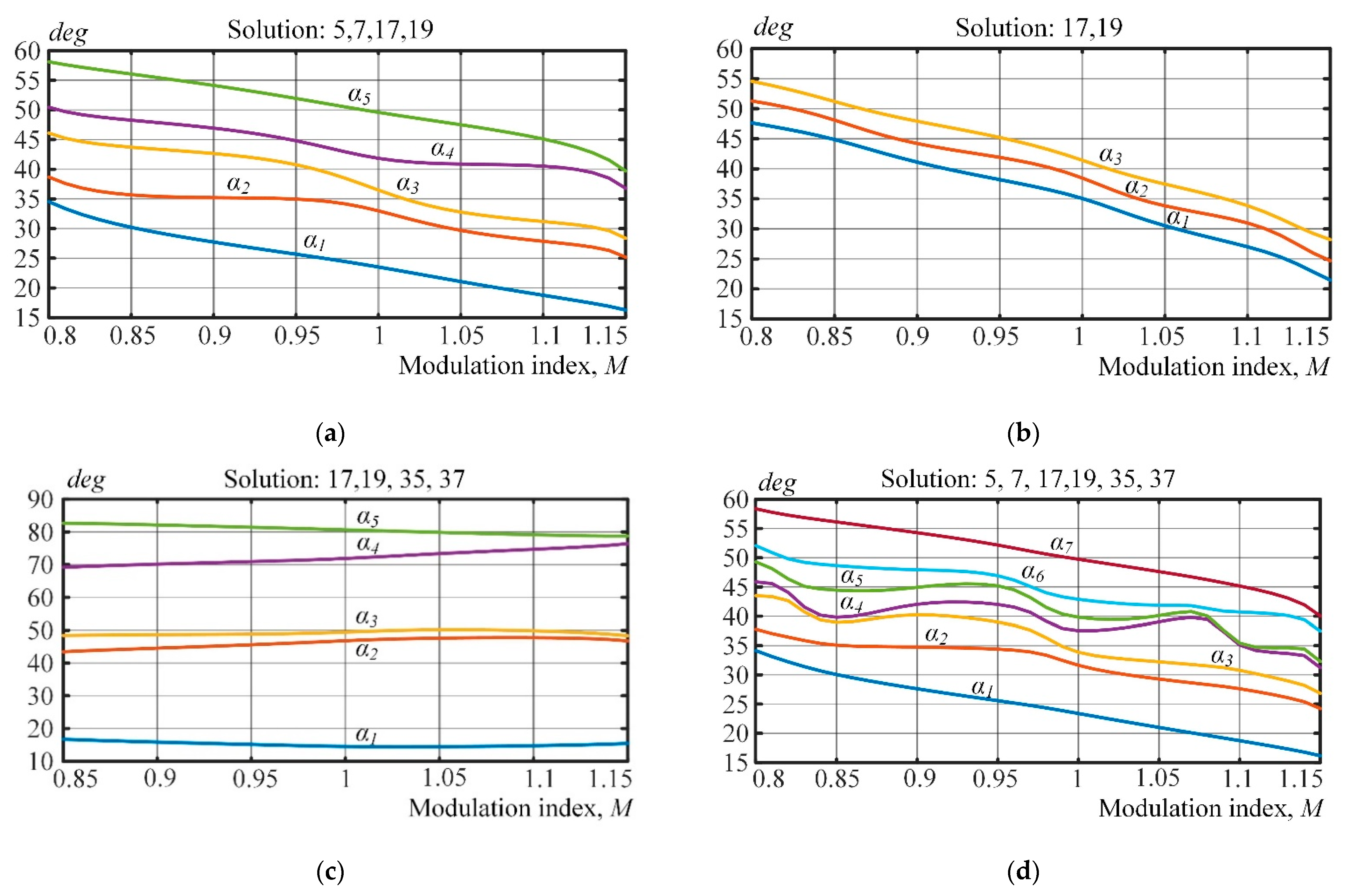
3.4. Programmed Pulse-Width Modulation (PWM)

AFEs use commonly known AC voltage modulation methods, including six-pulse modulation, sinusoidal PWM, space vector modulation, and programmed PWM [16,17]. In case of high power (>1 MW) and medium voltage (3.3 kV to 10 kV), the switching frequency of semiconductor switches in the FC has to be limited to about 450 Hz [18]. In this case, only programmed PWM can modulate an AFE AC voltage waveform to be electromagnetically compatible with the grid [19]. Besides, there has not, so far, been any clear guidelines on how to rate the individual voltage and current harmonic factors after the 50th harmonic, which are important for high-power nonlinear equipment [20].
The object under consideration uses programmed PWM voltage waveform in three three-level AFEs with harmonics 17 and 19 eliminated, which corresponds to an average switching frequency of ~150 Hz. The scientific literature refers to such programmed PWM as selective harmonic elimination pulse-width modulation (SHEPWM) [21].
Figure 4 shows a typical voltage waveform with quarter-wave symmetry in a three-level converter that uses programmed PWM [22,23,24]. The programmed waveform is attained by switching the semiconductor modules at the right time at the switching angles α 1 , α 2 , , α N , whereby N such modules within [0, π/2] must be switched over a quarter-cycle provided that 0 < α 1 < α 2 < < α N < π / 2 . N can be found from [25]:
N = f swave f ,
where fswave is the average semiconductor switching frequency and f is the AFE voltage frequency.
Thus, programmed PWM has a variable period that depends on the time between the preconfigured switching angles [26].
By applying Fourier transform, this signal can be written as
V ao ( ω t ) = a 0 2 + n = 1 [ a n cos ( n ω t ) + b n sin ( n ω t ) ] ,
where n is the harmonic number and an и bn are Fourier series coefficients.
{ a n = 1 π 0 2 π V ao ( ω t ) cos ( n ω t ) d ( ω t ) n = 0 , 1 , , b n = 1 π 0 2 π V ao ( ω t ) sin ( n ω t ) d ( ω t ) n = 1 , 2 , , .
Given that the waveform features quarter-wave symmetry, Fourier transform only leaves odd sinusoidal components bn:
{ a n = 0 b n = { 0 , n = even 4 n π V dc 2 k = 1 n ( 1 ) k + 1 cos ( n α k ) , n = odd .
Equation (3) defines the relation between the switching angles and the AC voltage harmonic spectrum of a three-level AFE as
{ H 1 = k = 1 N ( 1 ) k cos ( α k ) = π 4 M , H n = k = 1 N ( 1 ) k cos ( n α k ) = 0
where Hn is the level of the nth harmonic, M is the modulation index and αk is the switching angle number ranging from 1 to n.
From the equation system (4), the number of eliminated harmonics can be found by the formula
n = N 1 .
The modulation index M ranges from 0 to Mmax, which can be found by the formula
M max = b 1 / ( V dc / 2 ) = 4 π .
In order to solve this nonlinear algebraic equation to obtain the unknown variable, many of the methods used in optimization solvers are proposed [27,28,29,30]. For the sake of generality and easy implementation for general microcomputers, a trust-region dogleg algorithm is employed in order to solve the SHEPWM equations [31,32].
By default, the fsolve function in Matlab chooses the trust-region dogleg algorithm, and, therefore, can be applied in the m-file codes with the objective function (5) to solve the nonlinear equations of SHEPWM. For each Ma, this method runs in increments of 0.01 from 0 to 1. After a suitable initial value is given, one switching pattern can be achieved.
The initial values for N switching angles (here, N = odd), unipolar SHEPWM can be derived as
{ α 2 k 1 0 = 30 ° + 120 ° k / ( N + 1 ) Δ α α 2 k 0 = 30 ° + 120 ° k / ( N + 1 ) + Δ α α N 0 = 90 ° Δ α .
where k = 1 , 2 , , ( N 1 ) / 2 and Δ α is an optimal small angle, which is used to avoid singularity of the fsolve function. After testing, Δ α = 0.3 ~ 0.5 and some other values can ensure iterative convergence.
The equation system (5) produces four patterns for harmonic elimination:
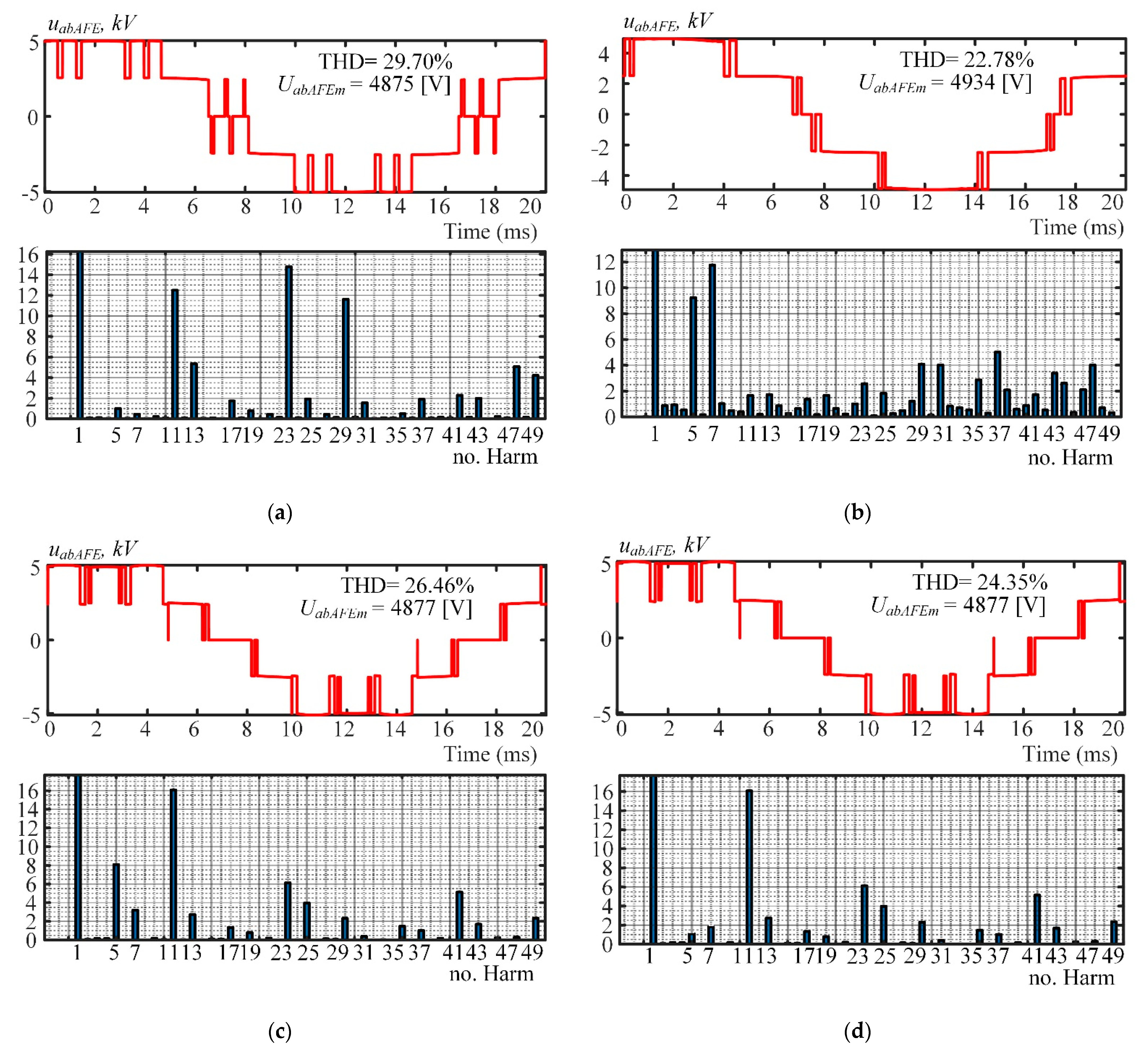
  • 5, 7, 17, and 19 in Pattern 1 (250 Hz);
  • 17 and 19 in Pattern 2 (150 Hz);
  • 17, 19, 35, and 37 in Pattern 3 (250 Hz);
  • 5, 7, 17, 19, 35, and 37 in Pattern 4 (350 Hz).
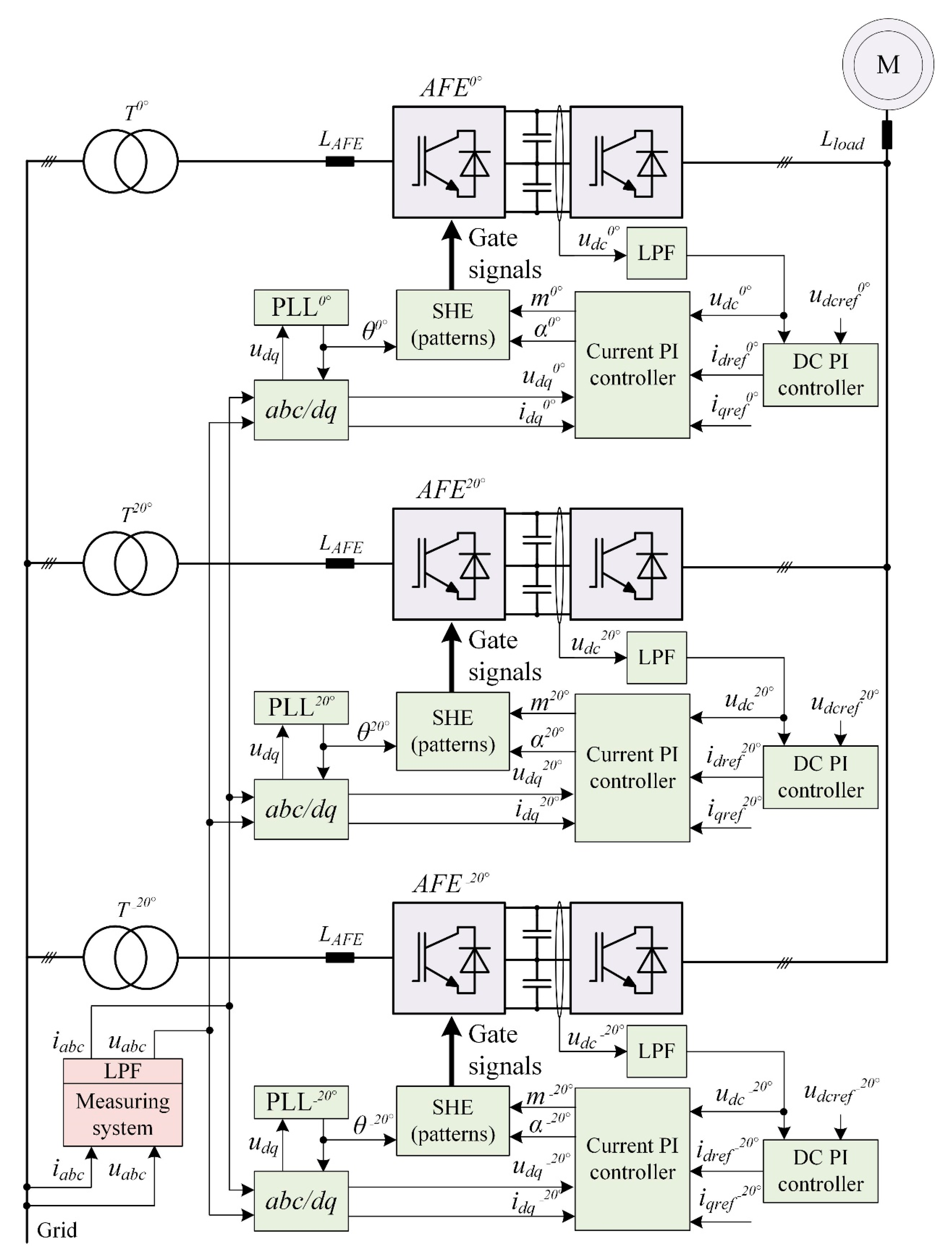
Figure 5 visualizes the results.

4. Control System

Most AFE control systems are based on the so-called voltage-oriented control (VOC). Linear controllers are either proportional (P) or proportional-integral (PI).
Figure 6 shows the circuit diagram of the control system used in the analyzed object. One peculiar feature of this circuit is that the three-phase current signals iаbc and voltage signals uаbc are measured at the primary side of the T, T20°, T−20° phase-shift transformers. This is possible thanks to the absence of other power-consuming equipment. Figure 6 uses the following notation: T, T20°, T−20° are phase-shift transformers; PLL, PLL20°, PLL−20° are units that synchronize voltages to the secondary windings of phase-shift transformers; iаbc and uаbc are the measured instantaneous phase currents and values on the primary side of the phase-shift transformers in abc coordinates; θ is the grid voltage space vector angle; θ, θ20°, θ−20° are the calculated voltage space vectors for the secondary windings of phase-shift transformers; idq are measured instantaneous phase currents and values on the primary side of the phase-shift transformers in dq0 coordinates; idq, idq20°, idq−20° are the measured instantaneous phase currents of AFEs in dq0 coordinates; idqref, idqref20°, idqref−20° are the configured phase currents of AFEs in dq0 coordinates; udq, udq20°, udq−20° are the measured instantaneous phase voltages of AFEs in dq0 coordinates; udc0°, udc20°, udc−20° are the measured instantaneous voltages of DC link capacitors in AFEs; udcref0°, udcref20°, udcref−20° are the configured AFE DC link capacitor voltages; m, m20°, m−20° are the AFE modulation indices; α, α20°, α−20° are the phase shifts between secondary windings of phase-shift transfers and phase voltages of AFEs; LAFE is the AFE input inductance; Lload is the FC input inductance; LPF are lowpass filters.
This paper does not dwell upon the synthesis of a current and voltage control system. Controllers are synthesized by cascade control.
Table 4 shows the parameters of the DC link voltage PI controller Kpdc and Kidc, as well as the parameters of the current vector PI controller Kpi and Kii in the orthogonal dq0 axes.
Voltage and current harmonic distortions were analyzed in Matlab/Simulink. The developed Matlab/Simulink model followed the description above and is not detailed here.

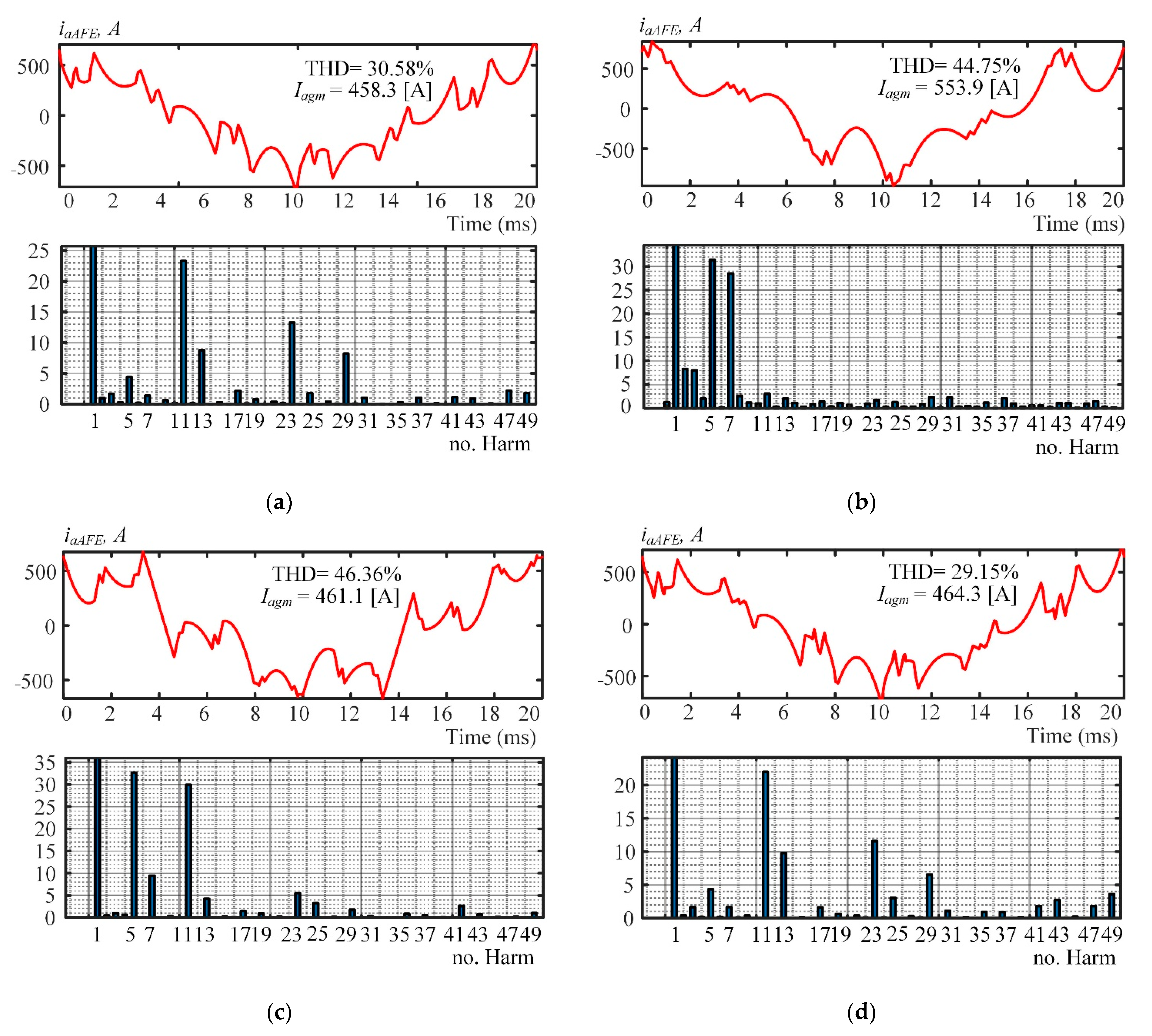
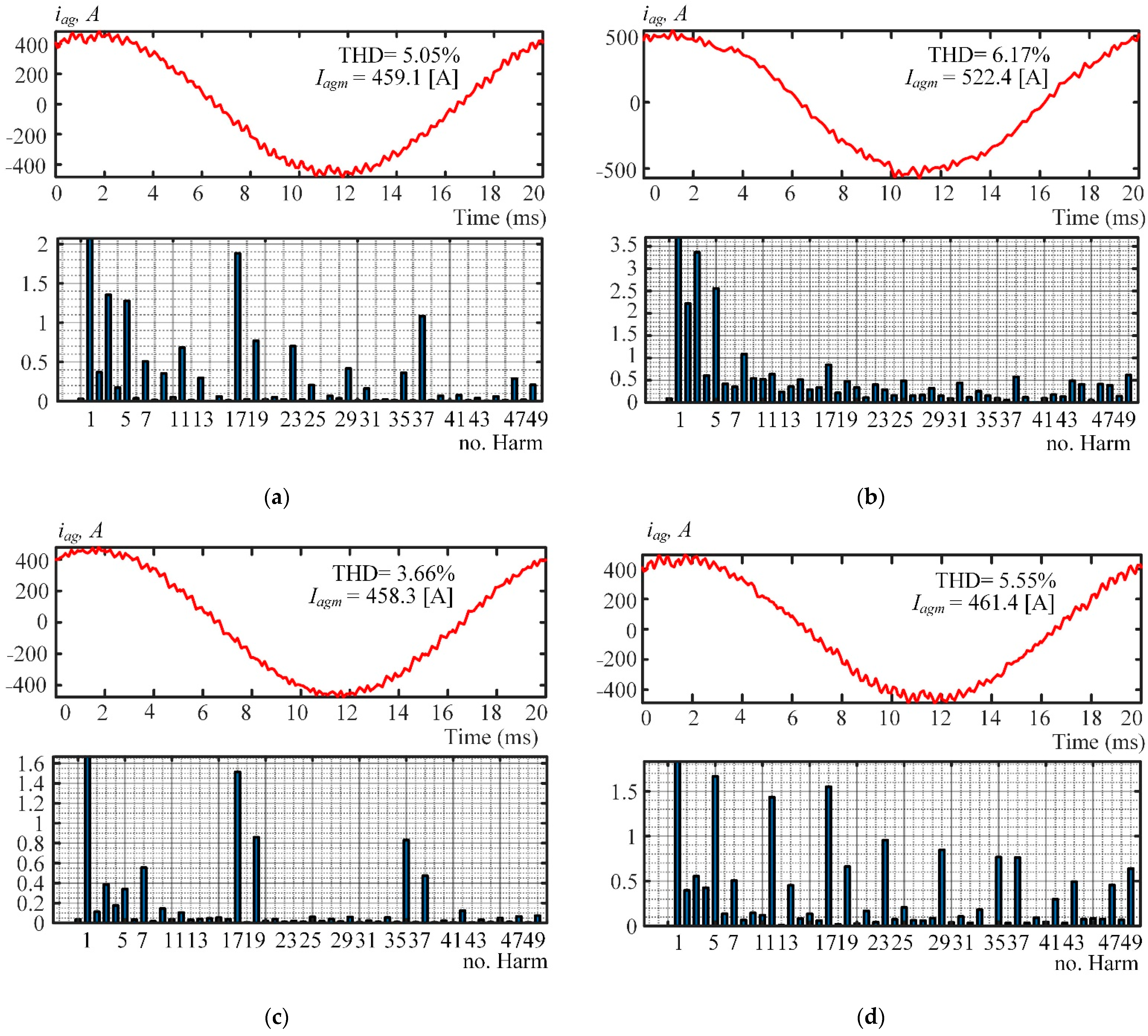
5. Simulation Results and Discussion

Voltage and current harmonic distortions were analyzed in Matlab/Simulink. The developed Matlab/Simulink model followed the description above and is not detailed herein for complexity and space considerations. Figure 7, Figure 8 and Figure 9 show the most visual results of simulating the currents of the object with four patterns obtained in Section 3.
Figure 7 shows the results of simulating the three-level AFE-consumed rated current iaAFE in the secondary winding of one of the three phase-shift transformers. Analysis of the data produced calculations of the total harmonic distortions (THD) and individual harmonic factors for up to the 50th iaAFE harmonic.
Figure 7a,c clearly shows iaAFE to have ~30% THD in Patterns 1 and 4, which is about 1.5 times less than in Patterns 2 and 3. This is because that the individual harmonic factors of iaAFE harmonics 5 and 7 have the greatest effect in the visible spectrum. Apparently, eliminating harmonics 35 and 37 (Patterns 3 and 4) results in no significant improvement in the harmonic spectrum of iaAFE. The reason is that the inductive reactance of the AFE input is sufficient to passively filter out the harmonics on this order.
Simulation results were performed for a rate modulation index 1.107. Figure 7, Figure 8 and Figure 9 show the obtained current and voltage THD considering harmonics up to 50th order.
Therefore, Pattern 1 with harmonics 5, 7, 17 and 19 eliminated is recommended to prevent the secondary windings of the phase-shift transformers from overheating. Pattern 2, which is currently in use and eliminates harmonics 17 and 19, is not recommended.
Figure 8 shows the results of simulating the rated current iag drawn from the grid by the three three-level AFEs in an 18-pulse connection. Figure 8c clearly shows that the THD of iag has the best value (3.66%) in Pattern 3, which is 1.39% less than in the case of the recommended Pattern 1 (see Figure 8a). The reason is that 18-pulse connection filters out harmonics of secondary-winding currents except 18n ± 1 (n = 1, 2, …, ∞).
Thus, the quality of the current iag in the recommended Pattern 1 (harmonics 5, 7, 17, and 19 eliminated) is not far below that in Pattern 3. Compared to Patterns 2 (Figure 8b) and 4 (Figure 8d), the quality of iag in Pattern 1 has better THDs and individual harmonic factors for up to the 50th harmonic.
Figure 9 shows the readings of phase-to-phase AFE voltage in the secondary winding of the −20° phase-shift transformer. Figure 9a demonstrates that the THD of uabAFE has a subpar value (29.70%) in Pattern 1, and an increase of 3–5% from Patterns 2, 3 and 4 (see Figure 8b,c). However, this does not cause significant issues with the AFE current as shown in Figure 7 and Figure 8.
As shown in Figure 7, Figure 8 and Figure 9, the four patterns produced very similar results, but in Pattern 1, the switching angle provided optimal current harmonic distortions in the 18-pulse connection. On the other hand, Pattern 3 of the SHEPWM strategy provided the best current in the grid. It could be successfully used in AFE operations while the phase-shifting transformers are running at nominal temperatures.
In the spectra under consideration, one can note the harmonics that the 18-pulse connection should have filtered out (see harmonic spectra in Figure 7, Figure 8 and Figure 9). Their presence could be due to the imperfect synchronization of three-level AFE control systems and errors in finding the phase-shift transformer winding ratios, which resulted in inaccurate semiconductor module switching angles.

6. Conclusions

Low switching selective harmonic elimination by programmed PWM for multipulse connections of AFEs can produce a high-quality current harmonic spectrum. The proposed implementation of the SHEPWM method can be applied to NPC topology of AFEs. A trust-region dogleg algorithm was applied to calculate switching patterns of SHEPWM technique and one universal formula for calculating initial values of SHEPWM technique is proposed. Several results of 18-pulse AFE rectifiers proved the validity of the algorithm with this formula.
To the authors’ knowledge, this paper is the first to analyze current harmonic distortions in an 18-pulse connection of three-level AFEs featuring a programmed PWM with four patterns that eliminate the following harmonics: 5, 7, 17 and 19; 17 and 19; 17, 19, 35 and 37; and 5, 7, 17, 19, 35 and 37. The results helped find the best such waveform to prevent phase-shift transformers from overheating, i.e., one with harmonics 5, 7, 17 and 19 eliminated. These results are highly versatile and could be used in similar research of other multipulse connections in order to ensure the electromagnetic compatibility of AFEs with programmed PWM.

Author Contributions

Methodology and validation, A.S.M.; writing—original draft preparation, A.S.M. and T.J.; writing—review and editing, A.S.M. and T.J.; investigation, A.S.M. and T.J.; project administration and supervision, A.A.R. and V.R.G.; supervision, A.S.M.; software, T.A.L. All authors have read and agreed to the published version of the manuscript.

Funding

The research was funded by RFBR and Chelyabinsk Region, project number 20-48-740008.

Conflicts of Interest

The authors declare no conflict of interest.

References

  1. Abu-Rub, H.; Bayhan, S.; Moinoddin, S.; Malinowski, M.; Guzinski, J. Medium-Voltage Drives: Challenges and existing technology. IEEE Power Electron. Mag. 2016, 3, 29–41. [Google Scholar] [CrossRef]
  2. Jing, T.; Maklakov, A.S. A Review of Voltage Source Converters for Energy Applications. In Proceedings of the Ural Conference on Green Energy (UralCon) 2018 International, Chelyabinsk, Russia, 4–6 October 2018; pp. 275–281. [Google Scholar]
  3. Franquelo, L.G.; Rodriguez, J.; Leon, J.I.; Kouro, S.; Portillo, R.; Prats, M.A.M. The age of multilevel converters arrives. IEEE Ind. Electron. Mag. 2008, 2, 28–39. [Google Scholar] [CrossRef] [Green Version]
  4. Kouro, S.; Rodriguez, J.; Wu, B.; Bernet, S.; Perez, M. Powering the Future of Industry: High-Power Adjustable Speed Drive Topologies. IEEE Ind. Appl. Mag. 2012, 18, 26–39. [Google Scholar] [CrossRef]
  5. Leon, J.I.; Vazquez, S.; Franquelo, L.G. Multilevel Converters: Control and Modulation Techniques for Their Operation and Industrial Applications. Proc. IEEE 2017, 105, 2066–2081. [Google Scholar] [CrossRef]
  6. Perez, M.A.; Bernet, S.; Rodriguez, J.; Kouro, S.; Lizana, R. Circuit Topologies Modeling Control Schemes and Applications of Modular Multilevel Converters. Power Electron. IEEE Trans. 2015, 30, 4–17. [Google Scholar] [CrossRef]
  7. De Caro, S.; Foti, S.; Scimone, T.; Testa, A.; Cacciato, M.; Scarcella, G.; Scelba, G. THD and efficiency improvement in multi-level inverters through an open end winding configuration. In Proceedings of the Energy Conversion Congress and Exposition (ECCE), Milwaukee, WI, USA, 18–22 September 2016; pp. 1–7. [Google Scholar]
  8. Nikolaev, A.A.; Bulanov, M.V.; Shakhbieva, K.A. Development of Improved PWM Algorithm of Active Rectifier with Function of Resonant Phenomena Adaptation in Electrical Networks of Medium Voltage. In Proceedings of the 2020 International Conference on Industrial Engineering, Applications and Manufacturing (ICIEAM), Sochi, Russia, 18–22 May 2020; pp. 1–6. [Google Scholar]
  9. Marquez Alcaide, A.; Leon, J.I.; Laguna, M.; Gonzalez-Rodriguez, F.; Portillo, R.; Zafra-Ratia, E.; Vazquez, S.; Franquelo, L.G.; Bayhan, S.; Abu-Rub, H. Real-Time Selective Harmonic Mitigation Technique for Power Converters Based on the Exchange Market Algorithm. Energies 2020, 13, 1659. [Google Scholar] [CrossRef] [Green Version]
  10. Saleem, M.; Choi, K.-Y.; Kim, R.-Y. Resonance damping for an LCL filter type grid-connected inverter with active disturbance rejection control under grid impedance uncertainty. Int. J. Electr. Power Energy Syst. 2019, 109, 444–454. [Google Scholar]
  11. Paice, D.A. Multipulse Methods and Transformers. In Power Electronics Converter Harmonics: Multipulse Methods for Clean Power; Wiley-IEEE Press: Hoboken, NJ, USA, 1996; pp. 25–37. [Google Scholar]
  12. Kornilov, G.P.; Nikolaev, A.A.; Khramshin, T.R. Mathematical Modeling of the Metallurgical Plants’ Electrotechnical Complexes; Nosov Magnitogorck State Technical University: Magnitogorsk, Russia, 2012. [Google Scholar]
  13. Hoevenaars, A.; Farbis, M.; McGraw, M. Active Harmonic Mitigation: What the Manufacturers Don’t Tell You. IEEE Ind. Appl. Mag. 2020, 26, 41–51. [Google Scholar] [CrossRef]
  14. Kouro, S.; Malinowski, M.; Gopakumar, K.; Pou, J.; Franquelo, L.G.; Wu, B.; Rodriguez, J.; Pérez, M.A.; Leon, J.I. Recent Advances and Industrial Applications of Multilevel Converters. Ind. Electron. IEEE Trans. 2010, 57, 2553–2580. [Google Scholar] [CrossRef]
  15. Nabae, A.; Takahashi, I.; Akagi, H. New neutral-point-clamped PWM inverter. IEEE Trans. Ind. Appl. 1981, IA-17, 518–523. [Google Scholar] [CrossRef]
  16. Yan, Q.; Wu, X.; Yuan, X.; Geng, Y. An Improved Grid-Voltage Feedforward Strategy for High-Power Three-Phase Grid-Connected Inverters Based on the Simplified Repetitive Predictor. IEEE Trans. Power Electron. 2016, 31, 3880–3897. [Google Scholar] [CrossRef] [Green Version]
  17. Napoles, J.; Leon, J.I.; Portillo, R.; Franquelo, L.G.; Aguirre, M.A. Selective Harmonic Mitigation Technique for High-Power Converters. IEEE Trans. Ind. Electron. 2010, 57, 2315–2323. [Google Scholar] [CrossRef]
  18. Pérez-Basante, A.; Ceballos, S.; Konstantinou, G.; Pou, J.; Kortabarria, I.; de Alegría, I.M. A Universal Formulation for Multilevel Selective-Harmonic-Eliminated PWMWith Half-Wave Symmetry. IEEE Trans. Power Electron. 2019, 34, 943–957. [Google Scholar] [CrossRef]
  19. Al-Hitmi, M.; Ahmad, S.; Iqbal, A.; Padmanaban, S.; Ashraf, I. Selective Harmonic Elimination in a Wide Modulation Range Using Modified Newton–Raphson and Pattern Generation Methods for a Multilevel Inverter. Energies 2018, 11, 458. [Google Scholar] [CrossRef] [Green Version]
  20. Aguilera, R.P.; Lezana, P.; Konstantinou, G.; Acuna, P.; Wu, B.; Bernet, S.; Agelidis, V.G. Closed-loop SHE-PWM technique for power converters through Model Predictive Control. In Proceedings of the Industrial Electronics Society IECON), Yokohama, Japan, 9–12 November 2015; pp. 5261–5266. [Google Scholar]
  21. Leon, J.I.; Kouro, S.; Franquelo, L.G.; Rodriguez, J.; Wu, B. The Essential Role and the Continuous Evolution of Modulation Techniques for Voltage-Source Inverters in the Past Present and Future Power Electronics. Ind. Electron. IEEE Trans. 2016, 63, 2688–2701. [Google Scholar] [CrossRef]
  22. Zhang, Y.; Hu, C.; Wang, Q.; Zhou, Y.; Sun, Y. Neutral-Point Potential Balancing Control Strategy for Three-Level ANPC Converter Using SHEPWM Scheme. Energies 2019, 12, 4328. [Google Scholar] [CrossRef] [Green Version]
  23. Cheng, J.; Chen, D.; Chen, G. Modeling and Compensation for Dead-Time Effect in High Power IGBT/IGCT Converters with SHE-PWM Modulation. Energies 2020, 13, 4348. [Google Scholar] [CrossRef]
  24. Steczek, M.; Jefimowski, W.; Szeląg, A. Application of Grasshopper Optimization Algorithm for Selective Harmonics Elimination in Low-Frequency Voltage Source Inverter. Energies 2020, 13, 6426. [Google Scholar] [CrossRef]
  25. Maklakov, A.S.; Radionov, A.A.; Gasiyarov, V.R. Power factor correction and minimization THD in industrial grid via reversible medium voltage AC drives based on 3L-NPC AFE rectifiers. In Proceedings of the IECON Proceedings (Industrial Electronics Conference), Florence, Italy, 23–26 October 2016; pp. 2551–2556. [Google Scholar]
  26. Zhang, W.; Li, X.; Qiao, J.; Liu, X. Research on DC Voltage Utilization Ratio of Inverter SHEPWM Control Method Based on Immune Algorithm. In Proceedings of the 2019 22nd International Conference on Electrical Machines and Systems (ICEMS), Harbin, China, 11–14 August 2019; pp. 1–5. [Google Scholar]
  27. Siddique, M.D.; Mekhilef, S.; Shah, N.M.; Momon, M.A.; Mustafa, A. SHEPWM Based New Hybrid Multilevel Inverter Topology with Reduced Switch Count. In Proceedings of the 2019 21st European Conference on Power Electronics and Applications (EPE ‘19 ECCE Europe), Genova, Italy, 3–5 September 2019; pp. 1–9. [Google Scholar]
  28. Wu, W.; Liu, W.; Wang, J.; Zhou, X. Inner Relationship between SHEPWM and SVPWM in Tri-level Converter. In Proceedings of the 2019 14th IEEE Conference on Industrial Electronics and Applications (ICIEA), Xi’an, China, 19–21 June 2019; pp. 793–798. [Google Scholar]
  29. Liu, C.; Wang, Y.; Wang, J.; Yu, X.; Zhou, L.; Xu, J. A hybrid PWM strategy based on SVPWM and SHEPWM for high-power drive system. In Proceedings of the 2021 6th Asia Conference on Power and Electrical Engineering (ACPEE), Chongqing, China, 8–11 April 2021; pp. 1413–1417. [Google Scholar]
  30. Yang, Y.; Tang, Y.; Li, Y. Dead-Time Elimination Method of High Frequency Inverter with SHEPWM. In Proceedings of the 2019 14th IEEE Conference on Industrial Electronics and Applications (ICIEA), Xi’an, China, 19–21 June 2019; pp. 457–461. [Google Scholar]
  31. Shahmi Bin Bimazlim, M.A.; Ismail, B.; Aihsan, M.Z.; Khodijah Mazalan, S.; Muhammad Azhar Walter, M.S.; Khairul Hafizi Rohani, M.N. Comparative Study of Optimization Algorithms for SHEPWM Five-Phase Multilevel Inverter. In Proceedings of the 2020 IEEE International Conference on Power and Energy (PECon), Penang, Malaysia, 7–8 December 2020; pp. 95–100. [Google Scholar]
  32. Steczek, M.; Chudzik, P.; Szeląg, A. Application of a Non-carrier-Based Modulation for Current Harmonics Spectrum Control during Regenerative Braking of the Electric Vehicle. Energies 2020, 13, 6686. [Google Scholar] [CrossRef]
Figure 1. Object connection 18-pulse circuit diagram.
Machines 09 00127 g001
Figure 2. Winding connections in phase-shift transformers. (a) +20° winding circuit; (b) +20° primary voltage vector diagram; (с) +20° secondary voltage vector diagram; (d) −20° winding circuit; (e) −20° primary voltage vector diagram; (f) −20° secondary voltage vector diagram.
Machines 09 00127 g002
Figure 3. Three-level NPC topology.
Machines 09 00127 g003
Figure 4. Typical programmed PWM waveform of a three-level AFE.
Machines 09 00127 g004
Figure 5. Calculations of four AFE switching patterns. (a) Pattern 1 with harmonics 5, 7, 17 and 19 eliminated. (b) Pattern 2 with harmonics 17 and 19 eliminated. (c) Pattern 3 with harmonics 17, 19, 35 and 37 eliminated. (d) Pattern 4 with harmonics 5, 7, 17, 19, 35 and 37 eliminated.
Machines 09 00127 g005
Figure 6. Object control system.
Machines 09 00127 g006
Figure 7. Oscillograms of rated AFE current iaAFE in the secondary winding of a single phase-shift transformer. (a) Pattern 1; (b) Pattern 2; (c) Pattern 3; (d) Pattern 4.
Machines 09 00127 g007
Figure 8. Oscillograms of the rated phase current iag drawn from the grid by the three three-level AFEs. (a) Pattern 1; (b) Pattern 2; (c) Pattern 3; (d) Pattern 4.
Machines 09 00127 g008
Figure 9. Oscillograms of the line AFE voltage uabAFE. (a) Pattern 1; (b) Pattern 2; (c) Pattern 3; (d) Pattern 4.
Machines 09 00127 g009
Table 1. Motor specifications.
Ur, VIr, Аfr, HzPr, MWcos(φ)Rl, mOhmLl, mH
33002460101219.5432.15
Table 2. Three-level AFE specifications.
Ur, VIr, АUdcr, Vfsw, HzPr, MWEfficiencyr, %Cdc, µF
330080050203508.4976341.54
Table 3. Parameters of phase-shift transformers: 0°, +20° and −20°.
Sr, kVARU1r, VU2r, VI1r, АI2r, АUsc, %∆Psc, kW∆Pnl, kW
570010,0003300329.1997.216554.9
Table 4. Controller parameters.
KpdcKidc Kpi Kii
0.5201.525
Publisher’s Note: MDPI stays neutral with regard to jurisdictional claims in published maps and institutional affiliations.

