Article

Numerical and Experimental Investigation of Flow and Heat Transfer in Heat Exchanger Channels with Different Dimples Geometries

1
School of Mechanical and Electrical Engineering, Wenzhou University, Wenzhou 325035, China
2
The State Key Laboratory of Fluid Power and Mechatronic Systems, Zhejiang University, Hangzhou 310027, China
*
Author to whom correspondence should be addressed.
Machines 2021, 9(4), 72; https://doi.org/10.3390/machines9040072
Submission received: 27 February 2021 / Revised: 19 March 2021 / Accepted: 23 March 2021 / Published: 26 March 2021
(This article belongs to the Section Machine Design and Theory)

Abstract

:
The heat exchanger is widely applied to many axial piston machines, and its structure significantly affects the heat transfer performance. Flow characteristic and heat transfer performance in heat exchanger channels with different dimples geometries are numerically and experimentally analyzed in this research work. The objective is to present details of flow field structure and heat transfer mechanisms for the dimpled channel. The realizable k-ε turbulence model was employed in the numerical simulations with the Re range from 3500 to 20,000. The temperature contour, local streamlines, friction factor, and Nu were presented to illustrate the heat transfer enhancement mechanisms. From this investigation, it is found that dimples cause downward flow, improve the flow mixing and reattachment, interrupt the boundary layer and form periodic impingement flows and then greatly improve the heat transfer. The heat transfer coefficient of hemispherical dimple channels with the three kinds of dimple radius–depth ratios is the highest, and it is about 27.2% higher than that of the traditional rhombus dimple channel. Comparing to the rhombus dimpled channel, the lower flow friction performance of the hemispherical dimple channel depends on the lower dimple radius–depth ratio. The hemispherical dimpled channel present better overall thermal performance due to the strength and extent of the recirculation flow reduction.

1. Introduction

To meet the operation requirement of axial piston pump under high temperature condition, it is necessary to improve the thermal efficiency design of pump shell. It is urgent to develop more effective cooling strategy for pump shell [1]. For improving the internal cooling performance of pump shell, several of heat transfer enhancement techniques such as ribs, pins, and dimples have been widely adopted in heat exchangers field in last decades. Among them, dimples can provide comparable enhanced heat transfer capabilities of finned spoilers as eddy current generators, which promotes near-wall flow areas and reduces pressure loss. The dimples are regarded as one of the most effective structures for heat transfer enhancement in the industrial application because they have an advantage in large convective heat transfer coefficient and high surface area-to-volume ratio [2,3]. Thus, an insight into the flow dynamics, heat transfer and friction characteristics in dimpled channels should be conducted.
Many researchers have investigated the effects of various dimples on the heat transfer and friction characteristics of dimpled channels. The investigation pursued in [4] showed that the dimple surface presents the highest performance of heat transfer enhancement and the most favorable dimple geometric structures are optimized by using the performance evaluation plot of enhanced heat transfer techniques. Xie et al. [5] designed a high-efficient enhanced heat transfer tube with both dimples and protrusions (ETDP) aiming to improve heat transfer. The studies proved that the ETDP improved flow mixing and formed periodic jet flows, which had advantages in enhancing heat transfer rate and performance evaluation criteria. Wang et al. [6] studied the hydrodynamics and heat transfer characteristics of dimpled tubes with different arrangements. They concluded that the Nusselt number increases by 18.6–22.7% and the friction coefficient increases by 18.6–25.9% for the aligned arrangement. Chang et al. [7] experimentally investigated the thermal performance of hexagonal duct with dimpled wall. The results showed that Nusselt number and pressure drop coefficient of each hexagon tube were the influence parameters of the dimple structure design of the compact heat exchanger. Zheng et al. [8] numerically investigated the enhanced heat transfer enhancement in the discrete double inclined ribs tube. The results showed that the improvement of heat transfer in ribbed tube was higher about 1.8–3.6 times, and the friction coefficient was higher about 2.1–5.6 times than that of smooth tube. Wei et al. [9] discussed the heat transfer enhancement in a dimple channel, and the results demonstrated that the pressure drop of dimple channel was improved obviously comparing with smooth microchannel.
However, some other researchers also found that the traditional hemispherical dimple could meet the enhanced heat transfer level of the channel, and increased about 1.5–2.0 times of the heat reduction compared with smooth channel [10]. Afanasyev et al. [11] studied experimentally the friction and heat transfer on the surface of a spherical cavity system formed by turbulent streamlining, and their results showed that the shape of the heating surface had no obvious influence on the fluid dynamics of the flow, and the heat transfer enhancement is as high as 30–40%. Bunker and Donnellan [12] measured the heat transfer and friction coefficients of fully developed turbulent flow in a circular tube with six different dimple geometries. Coy and Danczyk [13] experimentally studied the heat transfer enhancement of spherical dimples on the tube wall. Compared to the smooth channel, the heat transfer enhancement effect of the spherical dimple array with the concave depth diameter ratio of about 50% was better. Rao et al. [14] studied the overall average heat transfer enhancement of the spherical dimple channel is 1.5–1.7 times than that of the fully developed flow in the smooth channel. Turnow et al. [15] numerically studied the mechanism of turbulent heat transfer enhancement in a spherical dimple. They reported that the dimpled channel provided the maximum thermal- hydraulic performance if the best ratio of depth to diameter of channel was chosen to 0.26. In Ref. [16], LES and URANS methods was used to vortex mechanism of heat transfer enhancement in a channel with spherical and oval dimples. It was concluded that a formation of vortex structures provided heat transfer enhancement on dimpled surfaces but increased pressure loss. The heat transfer could be significantly increased by rounding the dimple edge and use of oval dimples. Xie et al. [17] analyzed the flow characteristics and heat transfer performance for a rectangular channel surfaces with internal-protruded dimples. The investigation concluded that the internal-protruded dimple structures suppressed recirculation flows in the upstream parts of the dimples. Small-scale recirculation flows were mainly distributed around the internal protrusions. Shchukin et al. [18] experimentally studied the effect of external factors on the heat transfer enhancement of the spherical dimples. Leontieva et al. [19] experimentally investigated the heat transfer and the hydraulic drag in a plane surface with spherical dimple, and determined the Reynolds number dependence of the drag, heat transfer and thermal efficiency.
Many experimental and theoretical studies also studied the heat transfer mechanism and flow pattern of non-spherical dimples. Zhou et al. [20] experimentally and numerically investigated the influence of dimple shape on heat transfer enhancement. The result showed that the teardrop dimple provided the highest thermal efficiency among the four dimples. Isaev et al. [21,22] numerically investigated tornado-like enhancement of heat transfer for low-velocity motion of air in a rectangular channel with cavities. Kim et al. [23] investigated three-dimensional Reynolds-averaged Navier–Stokes analysis of cooling channel with inclined elliptic dimples and optimized geometric parameters of inclined elliptical dimples aiming to improve heat transfer enhancement. Yoon et al. [24] analyzed the thermal–hydraulic properties of the tear-drop dimples and the traditional dimples. It was confirmed that the thermal performance of tear-drop dimples is higher than that of the traditional dimples. Park and Ligrani [25] developed a new turbulence model to analyze the heat transfer and flow characteristics of seven kinds of dimple shapes. Ge et al. [26] studied the flows in a channel with a cosine-shaped dimple on the lower wall. They concluded that the enhancement of the pressure drag was induced by high pressure on the rear part of the cavity because the separation region in the cavity of the dimple became larger with an increase of Reynolds number. Lan et al. [27] applied dimple/protrusion technology to design a new rectangular channel and provided heat transfer enhancement at low pressure condition. Haque et al. [28] represented a 3-D numerical investigation of forced convection heat transfer over circular and oval tube banks with longitudinal vortex generators (LVGs) for flow through a fin-and-tube heat exchanger. From the above, only a few researchers paid attention to the parametric design of dimple structure to improve the heat transfer performance of dimple channel. The understanding of heat transfer and flow characteristics in the channel with traditional dimple shapes was still very limited.
From the literature, the geometry and spacing of dimple has a significant effect on hydraulic and thermal performance in the channel flow. Dimples of different geometrical shape are used on the surface for heat transfer enhancement. In spite of various works elucidating the impact of adding a single or number of dimples to a system in literature, there is not sufficient data regarding the study of a group of interacting dimples, more specifically at high Reynolds numbers. Especially, the rhombus and hemispherical geometries of dimples on the heat transfer surface is found fewer in literature.
In order to fill this gap, the main objective of this study is to provide a numerical investigation of thermal hydraulic performance for the dimpled channel with two different dimple geometries at Reynolds number ranged from 3500 to 20,000. Then, appropriate geometry of dimple pattern is chosen, which has highest thermal hydraulic performance, which can be attempted for cooling of a dimpled channel. The remainder of this study is organized as follows. A realizable k-ε turbulence model is employed in the numerical simulations developed in Section 2. The grid independence study using turbulence model is conducted for each case In Section 3. The experimental apparatus used to measure the fluid temperature of the heat exchanger with different dimple shapes in Section 4. In Section 5, Flow field structure and heat transfer mechanisms of the dimpled channel are investigated under the single phase condition. The influence of radius–depth ratio on the flow and heat transfer characteristics for all different dimpled channels is investigated based on numerical and experimental results. The thermal enhancement factor of dimpled channels also has been discussed. Generally, this study may provide some theoretical guidelines and suggestions in the potential application of the dimpled channel.

2. Model and Numerical Method

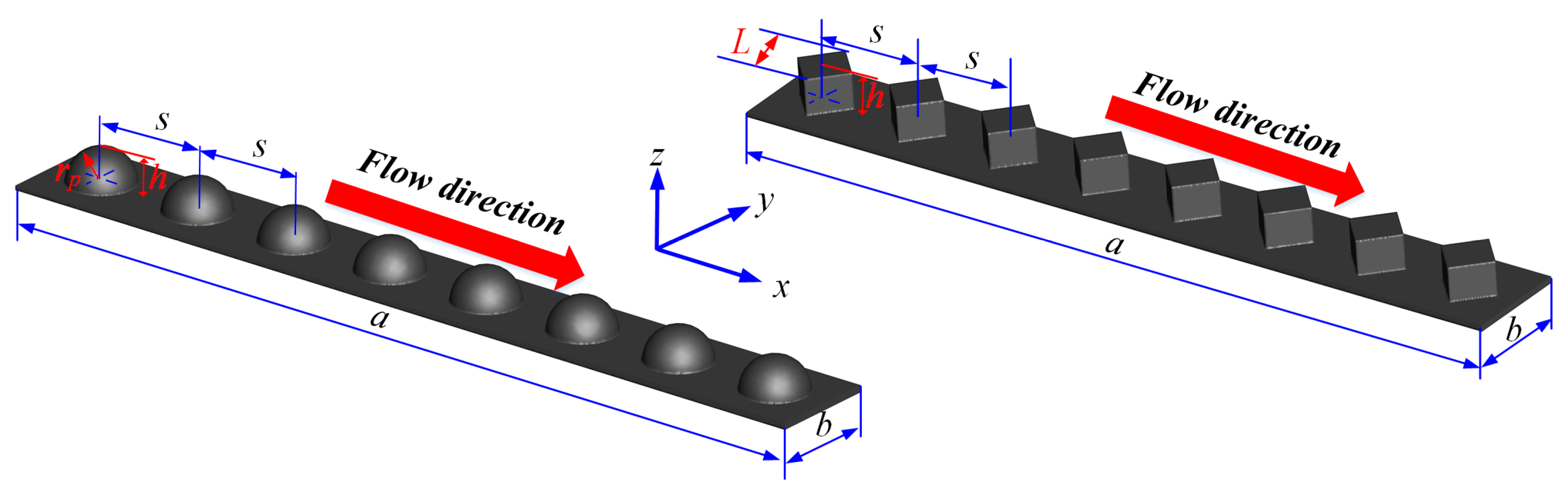
2.1. Geometrical Model

The thermal performance of the channel with dimples are studied in the present study. Figure 1 shows the geometrical structure of the dimpled channel. The model for this study is a rhombus channel with an array of dimples. The length (a) and width (b) of rectangular channel are 120 mm and 20 mm, respectively. The radius (rp) of hemispherical dimple is 3 mm and the width (L) of rhombus dimple is 3 mm. The radius–depth ratios (rp/h) of hemispherical dimples are defined as rp/h = 0.1, 0.2, 0.3, 0.4. Similarly, the length–depth ratios (L/h) of triangle dimples are adopted for this study as L/h = 0.1, 0.2, 0.3, 0.4. The distance (s) between each other dimples is 8 mm.

2.2. Mathematical Model and Governing Equations

The fluid field in channel is regarded as a three-dimensional turbulence, and it is assumed that the fluid is incompressible and has a constant property. Governing equations of continuity, momentum, and energy are solved to prediction flow characteristics and heat transfer performances. The realizable k-ε turbulence model is adopted in this study to close the governing equations. The associated governing equations of as follows [29]:
Continuity equation:
x i ( ρ v i ) = 0
where p is fluid pressure; vi is fluid velocity; ρ is fluid property; x is direction of coordinate.
Momentum equation:
ρ F i p x i + μ ( 2 v i x i 2 + 2 v i x j 2 + 2 v i x w 2 ) = ρ d v i d τ ρ F j p x j + μ ( 2 v j x i 2 + 2 v j x j 2 + 2 v j x w 2 ) = ρ d v j d τ ρ F w p x k + μ ( 2 v w x i 2 + 2 v w x j 2 + 2 v w x w 2 ) = ρ d v w d τ }
where F is body force; μ is oil viscosity; i, j, and w are direction of coordinate, respectively.
Energy equation:
T τ + v i T x i + v i T x j + v j T x k = λ ρ c p ( v i 2 T x i 2 + v i 2 T x j 2 + v j 2 T x k 2 )
where cp is specific heat; λ is thermal conductivity; τ is time.
The functions of turbulent kinetic energy and turbulent energy dissipation rate are written as [30]
Turbulence kinetic energy:
( ρ ε v i ) x i = x j [ ( μ + μ t σ k ) k x j ] + G k β ε
where μt is turbulent viscosity ratio; σk is turbulent kinetic energy; k is turbulent kinetic energy ratio; Gk is turbulent viscosity; ε is dissipation rate.
Specific dissipation rate (ε) equation:
x i ( ρ ε v j ) = x j [ ( μ + μ t σ ε ) ε x j ] + C 1 G k ε C 2 ε 2 k + υ ε
where Gk can be explained as follows:
G k = v i v j ¯ v i v j = μ t ρ ( v i v j + v j v i ) v i v j
G 1 = max [ 0.43 , μ t μ t + 5 ] , G 2 = 1.0 , σ k = 1.0 , σ ε = 1.2 , μ t = ρ C μ k 2 ε
where Cμ is constant value.

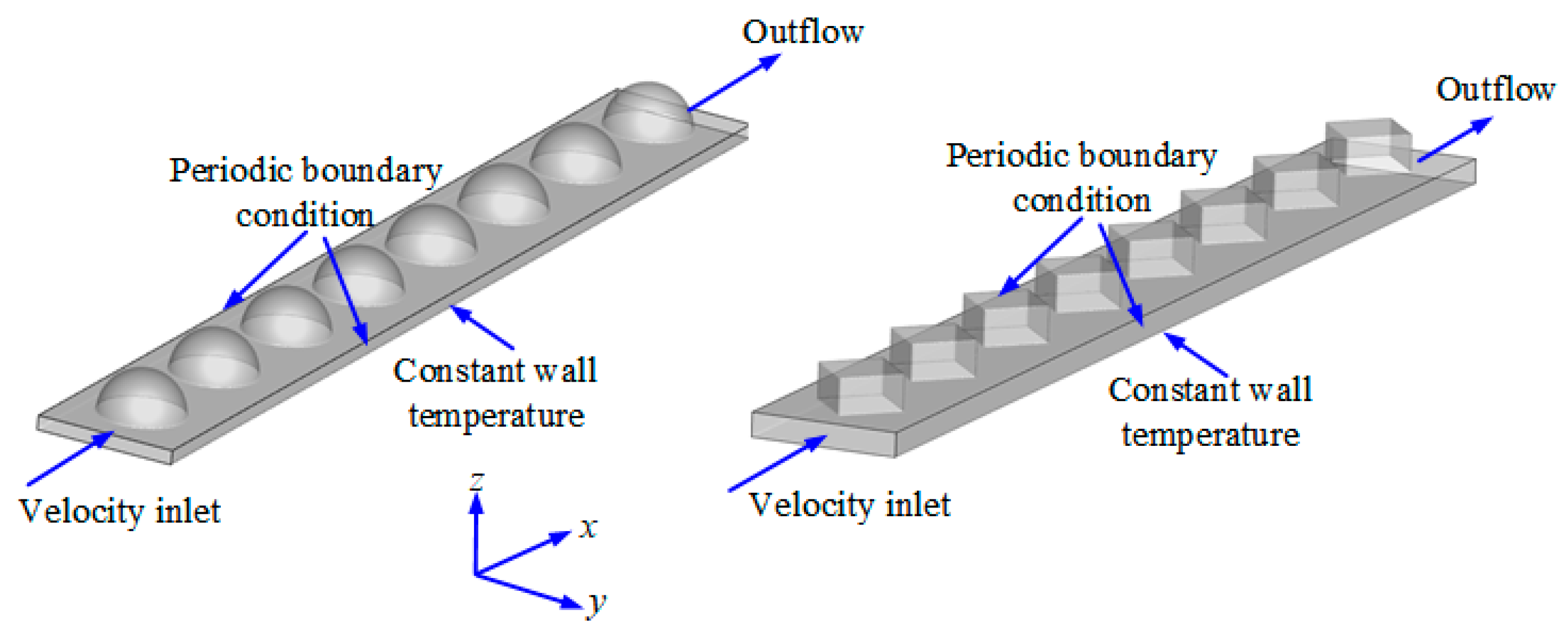
2.3. Boundary Conditions

Figure 2 shows the flow computational domain of a dimpled channel. The dimples are evenly located on the slipper surface.
Therefore, the periodic boundary condition can be expressed as [19]
v x ( x , y , 0 ) = v ( x , y , a ) , v y ( x , y , 0 ) = v ( x , y , a ) , v z ( x , y , 0 ) = m test m out w ( x , y , a )
k ( x , y , 0 ) = k ( x , y , a ) , ε ( x , y , 0 ) = ε ( x , y , a )
T ( x , y , 0 ) = T ( x , y , a ) Q C p m out
T = T w = 320 K
where mtest is mass flow rate; Tw is wall temperature; Q is total heat absorbed by heat transfer fluid; mout is outlet mass flow rate.

2.4. Data Reduction

The Reynolds number of fluid in a dimpled channel can be written as
Re = ρ v d μ
where d is diameter of channel; Re is Reynolds number.
The convective heat transfer coefficient between fluid and channel wall is calculated as [31]
h = Q ˙ A ( T w T ave )
where h is convective heat transfer coefficient; A is flow area; Tave is average fluid temperature; Q ˙ is heat transfer rate.
The mean temperature difference between the cooling wall and the heat flow is defined as
Δ T m = ( T w T in ) ( T w T out ) ln ( T w T in T w T out )
where ∆Tm is the mean temperature difference; Tout is outlet temperature; Tin is inlet temperature.
The Nusselt number and friction factor in the dimpled channel can be written as [32]
N μ = h d e λ
f = Δ p ( L d ) ( ρ μ 2 2 )
where L is channel length; de is equivalent diameter of channel; f is friction factor; ∆p pressure difference between inlet and outlet.
In this study, the governing equations of continuity, momentum and energy are discretized by the finite volume method, and all the governing equations are solved using ANSYS 14.5. The pressure velocity coupling problem is solved by simple algorithm, and the pressure equation is solved by the second order discrete scheme. At the same time, the second-order upwind discrete scheme is used to solve momentum, turbulent kinetic energy and turbulent dissipation rate. The grid should have a y+ value around or less than 1.0. Thus, the realizable k-ε turbulence model with enhanced wall functions can employed in the simulation for prediction of flow characteristics and heat transfer performances. The convergence criteria for the root mean square residuals of all variables are 10−6. To further ensure that a converged state has been obtained, the temperature and mass flow rate are monitored at the heated plate and channel outlet, respectively.

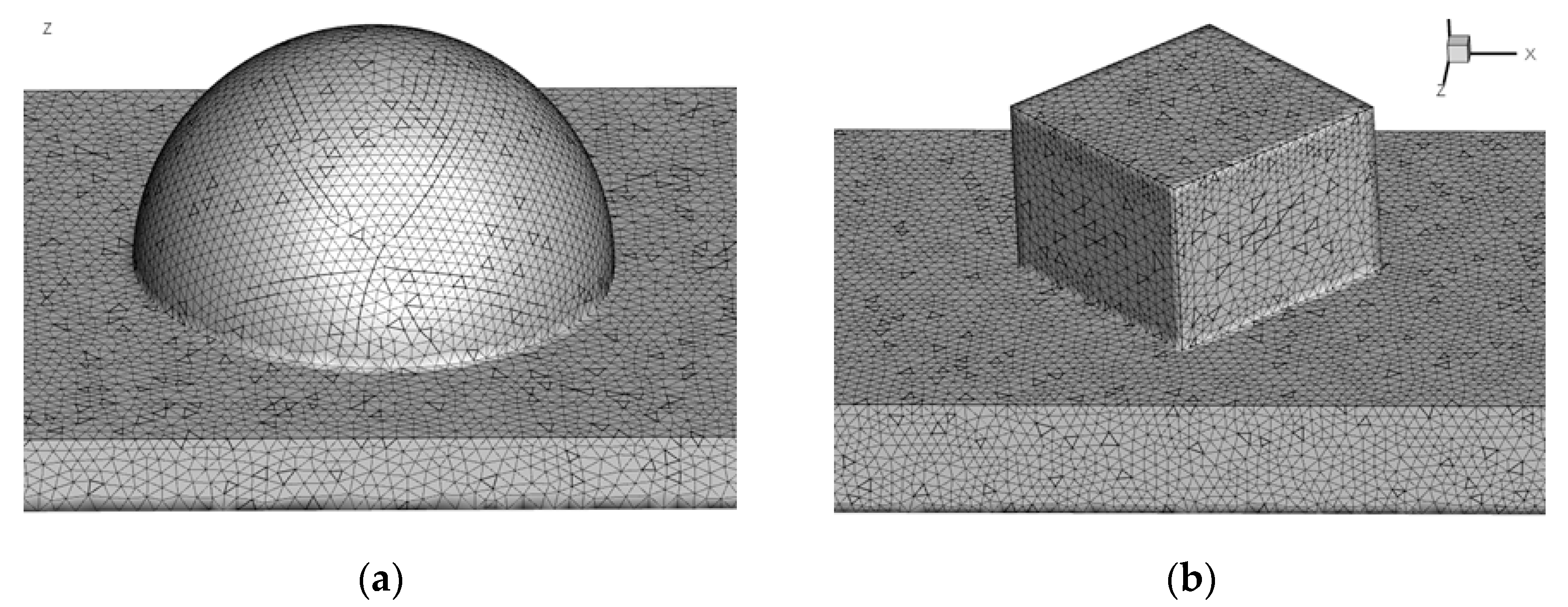
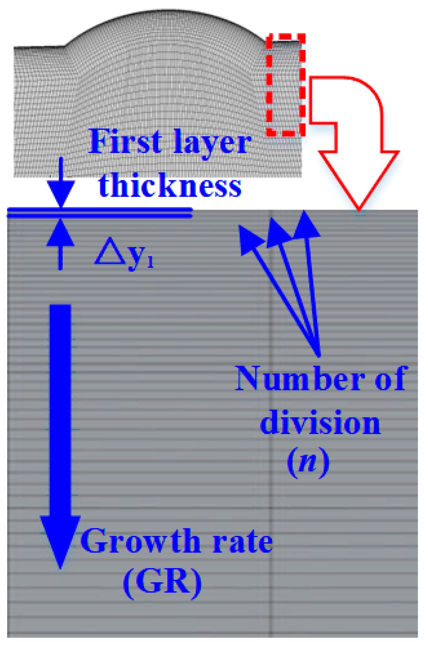
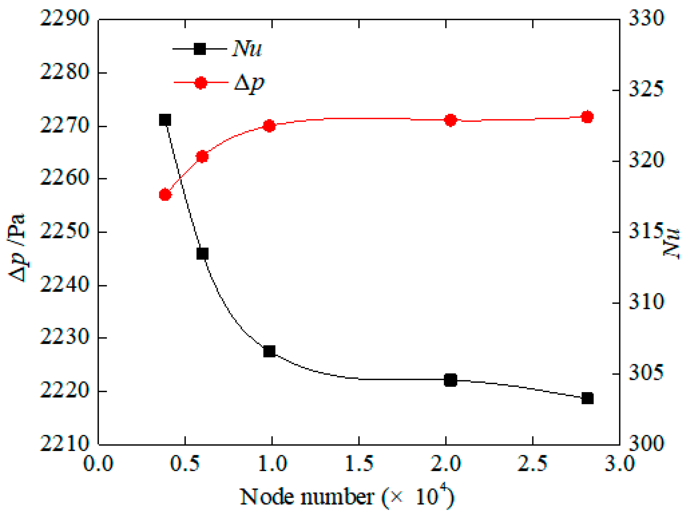
3. Grid Independence Study

To choose an appropriate grid number which can keep a balance between computational economy and prediction accuracy, the grid independence study using turbulence model is conducted for each case. For all cases, the hexahedral mesh is mesh the model because of its high quality. The grid near the boundary is refined because much more details about fluid field are needed, especially the details in the boundary layer. Grid structure is shown in Figure 3. Except that the algorithm applied in numerical method has effect on the accuracy of results, the accuracy is influenced by grid. Therefore, the grid independence is carried out to confirm that numerical results are free from the influence of grid and number of grids met the calculation accuracy requirements.
In order to capture the solution in viscous sub-layer near the wall, fine mesh is adopted for the near-wall region to satisfy (y+ ≈ 1) at the adjacent wall of near-wall regions, which is applicable with enhanced wall treatment for the studied range of Reynolds numbers. For capturing the boundary layer and satisfying the value of YPlus (y+ ≈ 1), grid parameters are used for the axisymmetric model as follows: First layer thickness (△y1 = 0.00215 mm), growth rate (GR = 1.02), and number of division(n = 120) as shown in Figure 4.
Figure 5 shows the effects of mesh sizes on the distribution of the Nusselt number and pressure difference through a dimpled channel. We conduct to the mesh independency test for hemispherical dimpled channel at Re = 12,000, and analyze the effect of five different grid densities of the channel on Nusselt value and pressure difference. The five configurations have grid layout with approximately 4682, 5325, 9634, 20,488, and 28,320 cells, respectively. When the grid number increases from 9634 to 28,320, the Nusselt number decreases from 322.4 to 323.13, and the pressure difference increases from 2227.6 Pa to 2218.6 Pa. It is clearly visible that after 20,488 further increasing the grid number causes negligible variations in local Nusselt number and pressure difference values on the dimpled channel region.
The grid independence validation is carried out using the dimple hexahedral mesh. Table 1 gives comparison in average Nusselt number and pressure difference as well as its difference among four mesh sizes. It can be seen that Nusselt number and pressure difference change by 0.017% and 0.094% from gird size of 4682 to 28,320, respectively. Consequently, the mesh size of 20,488 is adopted for the simulation of case. Simultaneously, the mesh sizes employed for other cases are ranging from 4682 to 28,320.

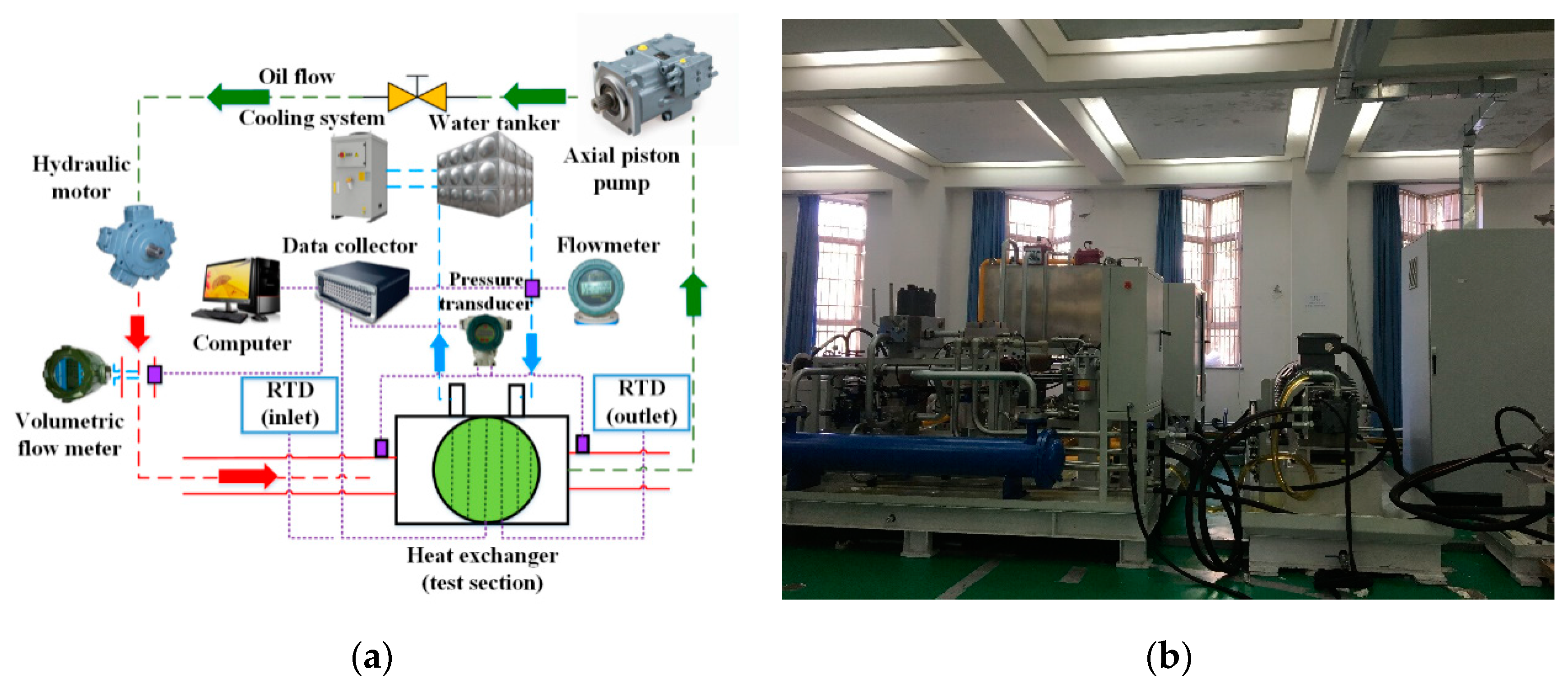
4. Experimental Apparatus

In order to the heat transfer performance of heat exchanger with hemispherical dimples, a test rig was set up and utilized at Wenzhou university, as shown in Figure 6. Cooling water is used as working fluid outside the tube bundle. The experimental device is mainly composed of a cooling water circulation system and a pump-motor control system. The system is insulated with 5 cm silicate to reduce heat loss. In the oil passage circulation system, hydraulic oil is pulled by a variable speed motor, and this method can maintain the inlet oil temperature of test section at approximately 60 °C in all the experiments. Then, the hot oil flows through the heat exchanger. The heat of the hot oil is transferred to the cooling water in the tube bundle. Finally, the cooler oil returns to the pump after passing through an oil flow stable section. In the cooling water circulation system, the 12 KW water cooler is connected with the water tank to keep the inlet water temperature of the heat exchanger at 35 °C. The cooling water is driven by the pump and circulates between the water tank and the heat exchanger and maintains a stable value of 2 m3/h. The cooling water is evenly distributed on the tube bundle, and the heat of hydraulic oil is absorbed by the cooling water.
The experimental data includes oil temperature, water temperature, pipe wall temperature, oil pressure difference, oil volume flow rate, and water mass flow rate. All data is obtained by Agilent collector and transmitted to the computer. The test parameters and instruments are shown in Table 2. In the current heat transfer experiments, the temperature measurement method is very important because it directly affects the calculation of convective heat transfer coefficient of heat exchanger channel.
In this study, the temperature measurements can be written as
Φ = Q A 0 Δ T m × 100 %
where Φ is temperature measurement; A0 is initial heating area.
The heat exchange between fluids is calculated as follows
Q h = m h C p p h ( T hi T ho )
Q c = m h C p p h ( T ci T co )
where Qh is oil heat exchange rate; Qc is water heat exchange rate; mh is heat fluid mass; ph is heat fluid density; Thi is oil inlet temperature; Tho is oil outlet temperature; Tci is inlet temperature of cold water; Tco is outlet temperature of cold water.
Table 3 expresses the experimental uncertainty as a percent deviation for each operating variable. In this experiment, the percent deviation can be calculated as follows:
ψ = x x av x av × 100 %
where x is measurement; xav is mean of a set of measurements; ψ is deviation.
Table 4 shows a typical example of heat load values for both fluids. In this table, Reh and Rec are the Reynolds numbers of hydraulic oil and water, respectively. The results show that the maximum heat exchange rate difference between hydraulic oil and water is 6.7%, and the minimum difference is 1.1%. There are include two main reasons. One reason is the heat dissipation of the insulation layer. The other reason is the experimental measurement error.
For the validation of the proposed model, the results for dimpled channel were determined using the proposed model and compared with the current experimental results. Figure 7 presents the comparison of the oil temperature along the x-direction in the dimpled channel obtained by the proposed model with the results determined experimentally. In Figure 7a, the trend of the numerical result for channel with hemispherical dimple is seen to be in line with the outcomes of the experimental test. The maximum and minimum absolute deviations of the numerical results from the experimental ones are 0.37% and 0.27%, respectively. In Figure 7a, for channel with rhombus dimple, the maximum and minimum absolute deviations between the numerical results and the experimental results are 0.43% and 0.03%, respectively. Thus, a good agreement has been achieved between the numerical simulation and the experimental data and the proposed numerical model can be used to predict the experimental results with reasonable accuracy and can therefore be used to analyze the other cases.

5. Results and Discussion

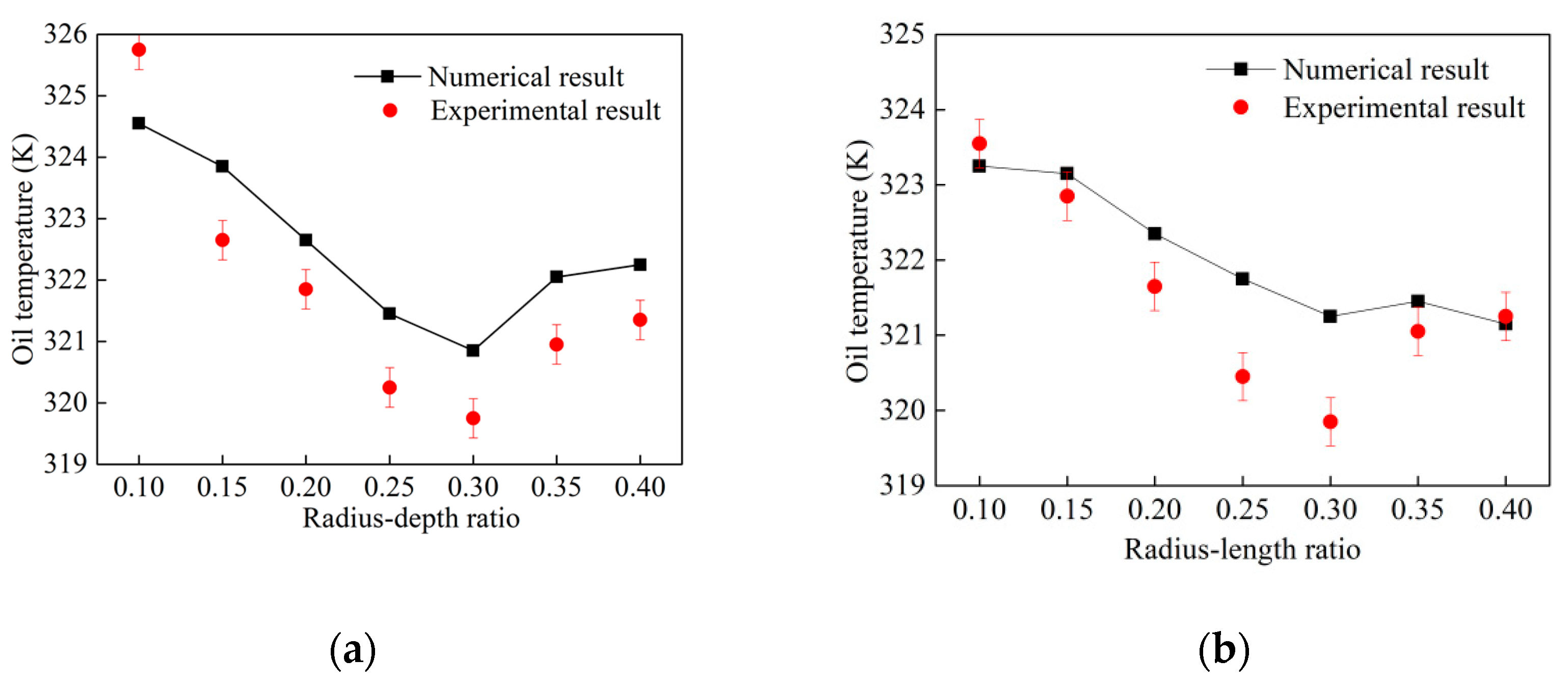
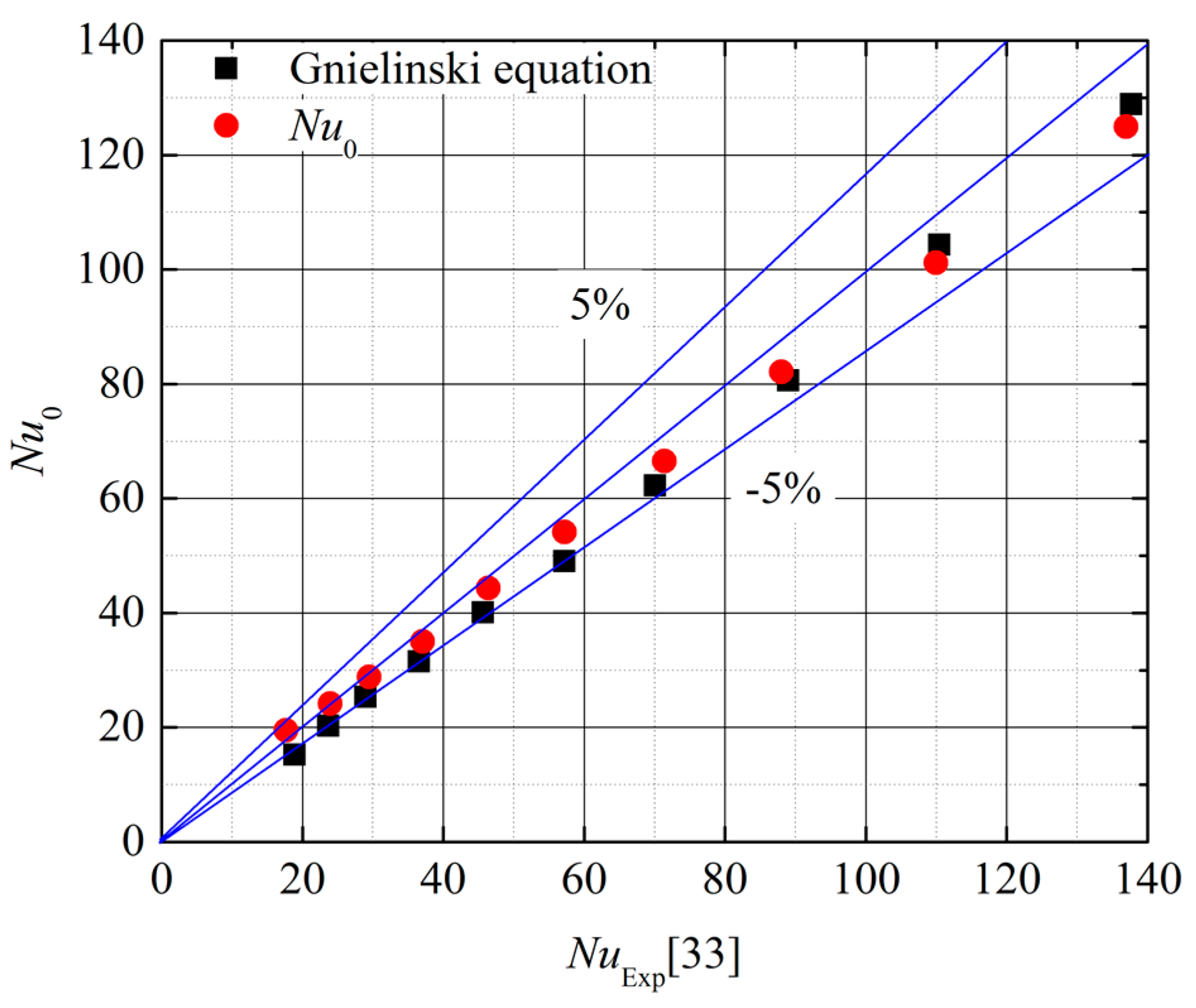
5.1. Validation with Empirical Equations

The averaged Nusselt number and friction factor of a smooth channel are chosen as the reference values for comparing the flow and thermal performance of the dimpled plates. The Nusselt number are calculated by Gnielinski empirical correlation. The criteria of heat transfer can be verified by the Nusselt number [33]. Therefore, the Nusselt number and Darcy friction coefficient for developed fluid region are defined as follows
N μ 0 = ( f 0 8 ) ( Re 1000 ) P r [ 1 + ( d L ) 2 3 ] 1 + 12 . 7 f 0 8 ( P r 2 3 1 )
where Nu0 is averaged Nusselt number in the fully developed fluid region; f0 is Darcy friction factor in the corresponding fully developed fluid region; Pr is Prandtl number.
The results based on CFD of friction factor is evaluated with empirical correlations to validate numerical results with experimental results. Thus, the Darcy friction factor proposed by Filonenko is used to evaluate flow resistance, as defined in Equation (22):
f 0 = ( 1.82 lgRe 1.64 ) 2
The numerical results of Nusselt number are compared with experimental results in Figure 8. The numerical results are in good agreement with empirical equations. The deviation of Gnielinski equation is all within 5% and the maximum value is about 3.7%.
Figure 9 shows the comparison between the numerical friction factor and empirical correlations. Obviously, the numerical results and the existing correlation have the variation trend and the difference value is very small. The average discrepancy of friction factor with Filonenko is within 5%. The results show that the numerical results are in good agreement with the maximum uncertainty of friction coefficient experimental results.

5.2. Flow Characteristics

To analyze the fluid flow and heat transfer characteristics in hemispherical and rhombus dimples channels, it is necessary to compare the calculation results with the result of reference [34]. Figure 10 shows the effect of Reynolds numbers on the Nusselt number of the dimpled channel with different dimple shapes. As Reynolds number increase, the Nusselt number of all channels increases. The Nusselt number of hemispherical dimple channel varies from 50 to 278, which is 1.16 times than that of a rhombus dimpled channel. Comparing to the hemispherical dimple channel, the Nusselt number of rhombus dimple channel decreased by 14.4%. Therefore, the channel with hemispherical dimples shows the highest Nusselt numbers among the two studied dimple shapes.
Figure 11 presents the effect of Reynolds numbers on the Nusselt number enhancement of the dimpled channel with different dimple shapes. The Nusselt number enhancement of the hemispherical dimple channel is about 1.2–1.62, which agrees well with the experimental data. The Nusselt number enhancement of the rhombus dimple channel is about 0.9–1.17, which is similar to the experimental values of the dimpled channel flow. For two kinds of dimpled channels, when the Reynolds number is more than 11,598, the heat transfer enhancement of dimpled channels seem to be independent of the Reynolds number. In the case of low Reynolds number at 5028, all the dimpled channels show significantly lower heat transfer enhancement, which is mainly due to the lower level of turbulent mixing induced by the dimples. When the Reynolds number is set to 5028, the heat transfer enhancement performance of rhombus dimple is 20.9% lower than that of hemispherical dimple, and such a rhombus dimple structure should be avoided for low Reynolds numbers.
Figure 12 shows the local Nusselt number distribution on the surface of dimpled channel under different Reynolds number. In this cases, the Reynolds numbers are chosen to 3000 and 20,000. The local Nusselt number can be defined as the local heat flow, the local temperature of the end wall and the local volume average temperature formed by the fluid flow. This result is consistent with the Nusselt number calculation based on the mean temperature difference, as shown in Equation (14) [35]. Due to the flow separation, all the dimples show a low heat transfer rate in the upstream half of the dimpled wall. As shown in Figure 12a, the convective heat transfer is distinctively enhanced in the front and back edge of the dimpled wall. The channel with hemispherical dimples shows the higher local heat transfer enhancement than that of the channel with rhombus dimples. This is because the straight slope of the upstream dimpled wall can effectively reduce the low heat transfer area. A more steeply curved wall in the upstream half of the hemispherical dimples could change the vortex structure to asymmetrical distribution in the dimples, which is consistent with the findings from Turnow et al. [16]. In Figure 12b, with the Reynolds numbers increase, the low heat transfer area in both dimple channels become smaller. This result could be because the heat transfer enhancement of the dimpled channel is significantly lower at a lower Reynolds number of 3000. Due to the effect of heat flow in inlet and outlet ports, there is high heat transfer performance of fluid flow at the leading edge of the concave channel, and then it drops rapidly.
Figure 13 shows the CFD results of the Nusselt number along the flow direction of different dimpled channels. The Nusselt number of fluid flow in the hemispherical dimpled channel is higher about 19.2% than that of rhombus dimpled channel. It also implies that the thermal entrance effect has greater influence on the heat transfer development of hemispherical channel. The heat transfer rate of hemispherical channel is higher than the rhombus channel.
Figure 14 shows the streamlines in a near-wall channel with different dimple shapes at the Reynolds number of 20,000. There is flow adhesion phenomenon near the leading edge of the dimpled channels. This will cause turbulent mixing in the near wall flow, which may eventually lead to heat transfer enhancement. Especially, the hemispherical dimples may obviously produce a larger high vortex region in the near-wall flow region than that of the rhombus dimples. For Rhombus dimples, the steep walls of inlet and outlet zones lead to flow separation, resulting in lower heat transfer performance. The surface streamlines of different channels can be used to compare the difference between the heat transfer enhancement zones on the dimpled surfaces.

5.3. Heat Transfer

Figure 15 shows the effect of Reynolds number on heat transfer enhancement factor (Nu/Nu0) in different dimpled channels. With the Reynolds number increase, the heat transfer enhancement factor decreases. When the Reynolds number is less than 5000, the decline rate of heat transfer enhancement factor is higher and becomes lower for Re = 5000–20,000. When the radius depth ratio of hemispherical dimpled channel increases from 0.1 to 0.3, the heat transfer enhancement factor increases in the case of same Reynolds number. The reason is attribute to the flow area in the hemispherical concave channel, which is directly proportional to the radius depth. With the increase of radius depth, the low temperature fluid can cover more heating area and improve the heat transfer effectively. Comparing to rhombus dimpled channel, the improvement of heat transfer enhancement factor in the hemispherical dimpled channel is about 6.5–13.5%. The phenomenon can be explained that rhombus dimpled channel destroys the thermal boundary layer and enhances heat transfer due to high flow turbulence and mixing.
Figure 16 shows the effect of Reynolds number on friction factor increment (f/f0) in different dimpled channels. For hemispherical dimpled channel, the friction factor increment decreases with the increasing of Reynolds number. When the Reynolds number is more than 10,000, there is small variation in the friction factor increment. For the same Reynolds number, the friction factor increment does increase monotonously as radius–depth ratio (rp/h) increase. The friction factor increases with the increasing of the length–depth ratio (L/h). If the Reynolds number is set to 15,000, the heat transfer enhancement factor for hemispherical dimpled channel is higher about 5% than that of rhombus dimple. The results can be explained that the viscous sublayer decreases with increasing of Re as mentioned for dimpled channel with hemispherical shape study.
Figure 17 shows the CFD results of the fluid temperature in the different dimpled channel for Re = 10,000. It can be seen that the two kinds of dimpled channel exist different heat transfer performance due to the thermal entrancement effect of fluid. There is a large area of low heat transfer area in the leading edge of the hemispherical dimple, and the heat transfer in the rear edge of the dimple is also very strong due to the flow separation. The heat transfer distribution of rhombus dimple is similar to that of hemispherical dimple, but the low heat transfer area is larger than that of hemispherical dimple, which is the reason why the overall heat transfer performance of rhombus dimple is lower than that of hemispherical dimple. In addition, hemispherical dimple has the smallest area of low heat transfer area, but the Nusselt number is more uniform. In practical, the hemispherical dimple shows more uniform temperature distribution of the heat transfer structure, which reduces the thermal stress and increases the service life.

5.4. Thermal Performance Evaluation

In this study, considering the penalty effect caused by friction loss, we can evaluate the heat transfer performance of different dimpled channels. According to the Ref [36], the main parameters include f1/3Re, (Nu/Nu0)/(f/f0) and Nutotal/Nu0. The above motioned parameters are proportional to the pumping power and are used to evaluate the overall thermal performance. The increased heat transfer area of dimples and the vortex flow generated by dimples near the wall promote enhanced heat transfer, so it needs to be evaluated with Nutotal. The total heat transfer rate includes the heat transfer contribution of the dimple surface and flat surface as the total heat transfer rate. Therefore, the total Nusselt number is defined by
N μ total = N μ 0 A wet A base
where Nutotal is total Nusselt number; Awet is total wetted heat area; Abase is base heating area.
Figure 18 shows comparison of numerical and experimental results in term of the heat transfer enhancement of fluid flow in different dimpled channels. The heat transfer enhancement of spherical dimple channel is about 1.25–1.42, which agrees well with the experimental result reported by Coy et al. [13]. The Nusselt number enhancement of rhombus dimple is about 1.0–1.2, which is close to the heat transfer enhancement values of the dimpled channel flow. For two kinds of the dimpled channels, when the f Re3 is more than 5000, the heat transfer enhancement value seems to be independent of the parameter f1/3Re. When the parameter f1/3Re is set to 5000, all the dimpled channels show appreciably lower heat transfer enhancement. This phenomenon can be explained that the lower level turbulent mixing is caused by the dimples. The hemispherical dimples show the lowest thermal performance, which is about 11.6% higher than the rhombus dimples.
Figure 19 shows the overall thermal performance of different dimpled channels considering the effect of the Reynolds number. Within the Reynolds number range of 3500–20,000, the overall thermal performance of the different dimpled channels firstly increase and then decrease with the Reynolds number. The numerical and experimental results show that the overall thermal performance of the hemispherical dimpled channels are basically the same trend when the Reynolds number increases from 3500 to 20,000. Especially, the hemispherical dimpled channels show the highest overall thermal performance, which are about 27.2% higher than the rhombus dimpled channels. The main reason can be explained that the combination of heat transfer enhancement and flow friction reduction plays an important role in overall thermal performance.
Based on the analysis of existing performance evaluation standards, Fan [37] proposed a performance evaluation chart to study the heat transfer characteristics by two main parameter performance indexes, including the heat transfer enhancement rate and the increment of friction coefficient. Figure 20 shows performance evaluation plot of different dimpled channels. According to the same pumping power line and the same pressure drop line, the quadrants with two coordinates greater than 1.0 are divided into three areas. As shown in Figure 20, heat transfer enhancement ratio is larger than friction factor increase ratio in Region 1. At the same pumping power, there exists the heat transfer enhancement in Region 2, but the increase of friction coefficient is greater than that of heat transfer enhancement at the same pressure drop. The heat transfer in Region 3 is actually depends on identical pumping power. It can be seen that Region 1 shows the best performance in heat transfer and energy saving, and the Region 4 is the worst. In particular, all data for hemispherical depressions with Re = 20,000 is located in region 1, and the other data is located in region 2.

6. Conclusions

The flow and heat transfer characteristics of channels with different dimples geometries are investigated in this study. The realizable k-ε turbulence model was employed in the numerical simulations with the Re range from 3500 to 20,000. The flow structure and heat transfer performance of different dimple channels with various dimple radius–depths ratios have been investigated and compared with each other. The mainly conclusions can be draw as follows:
(1)
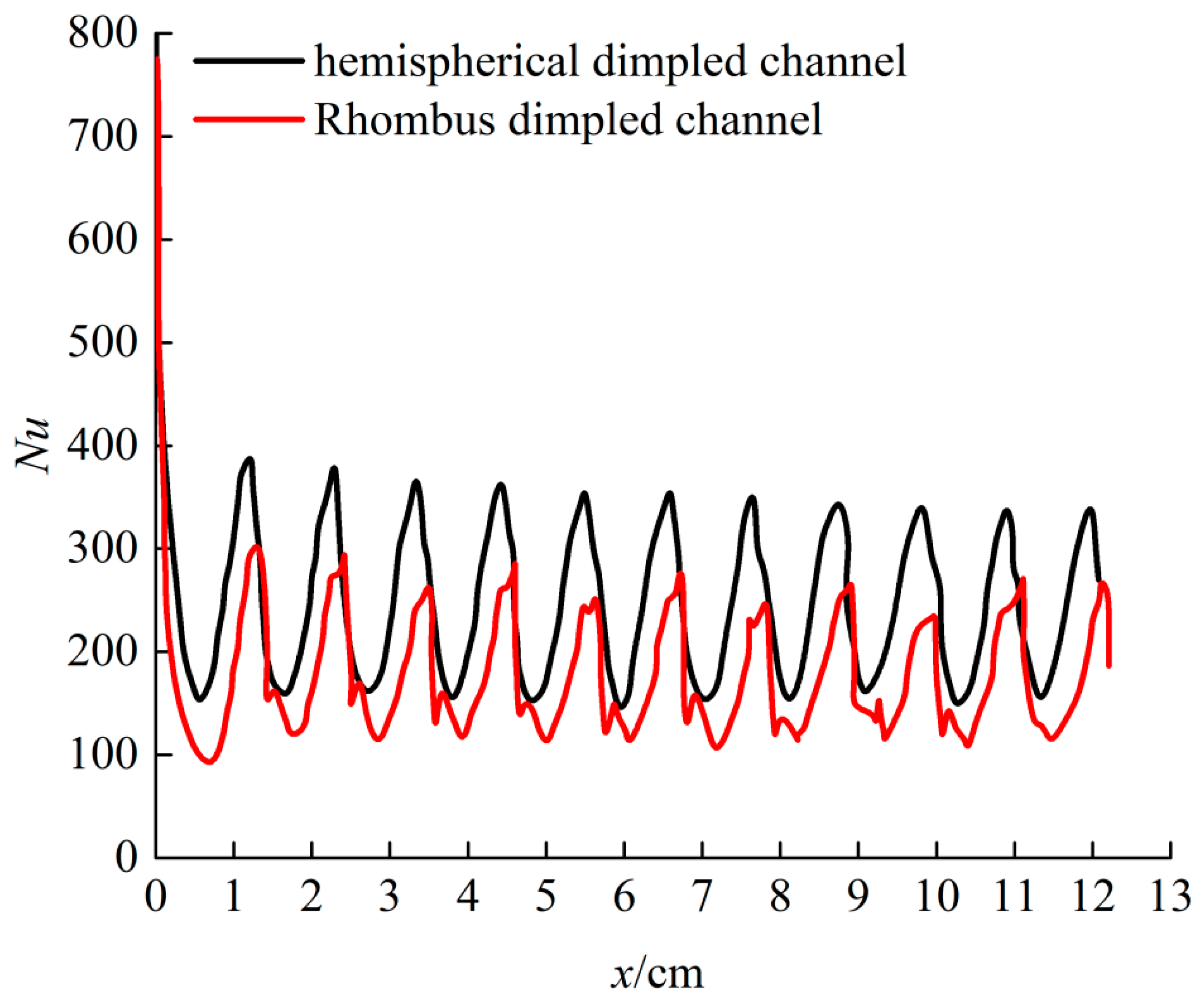
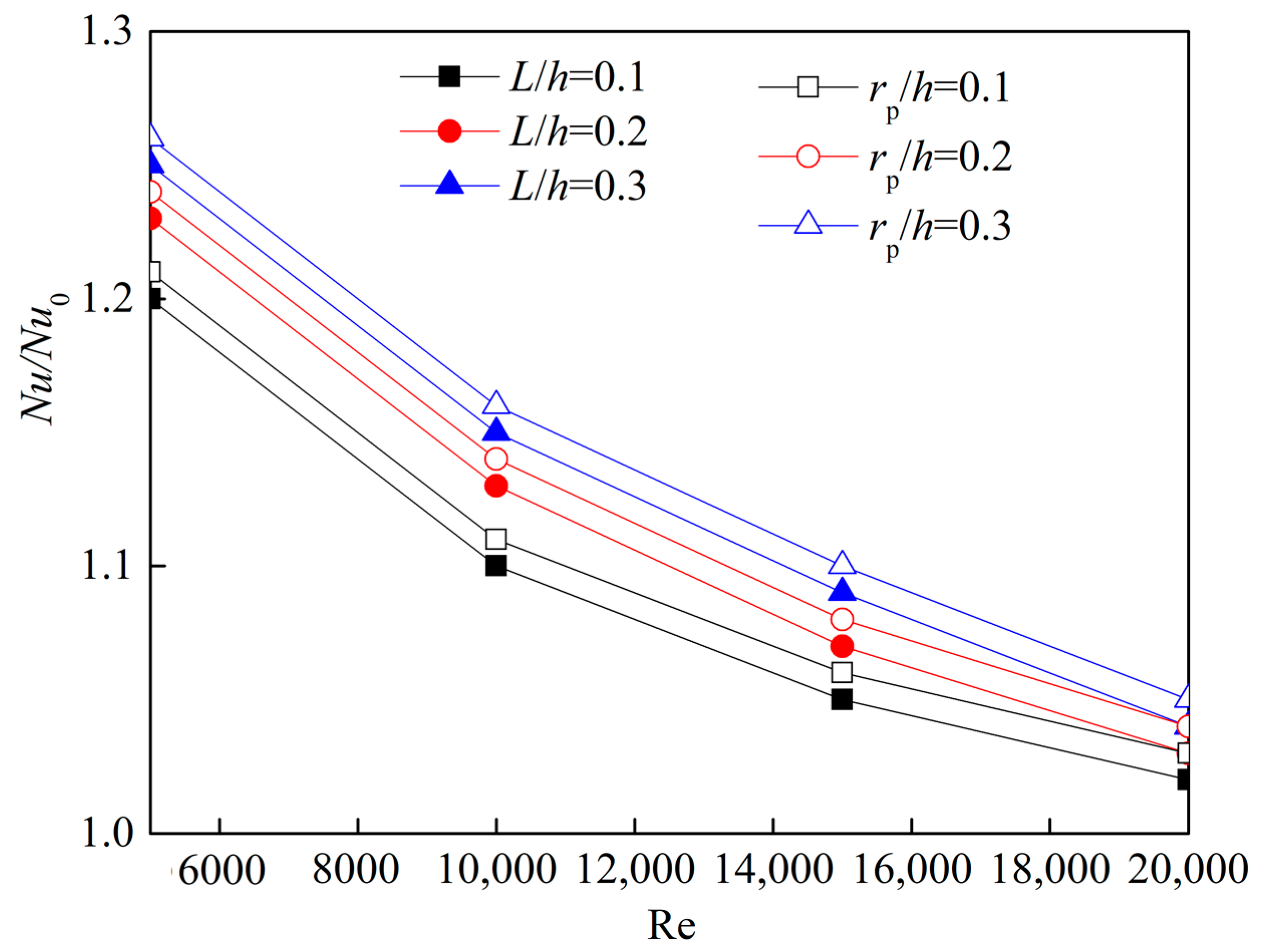
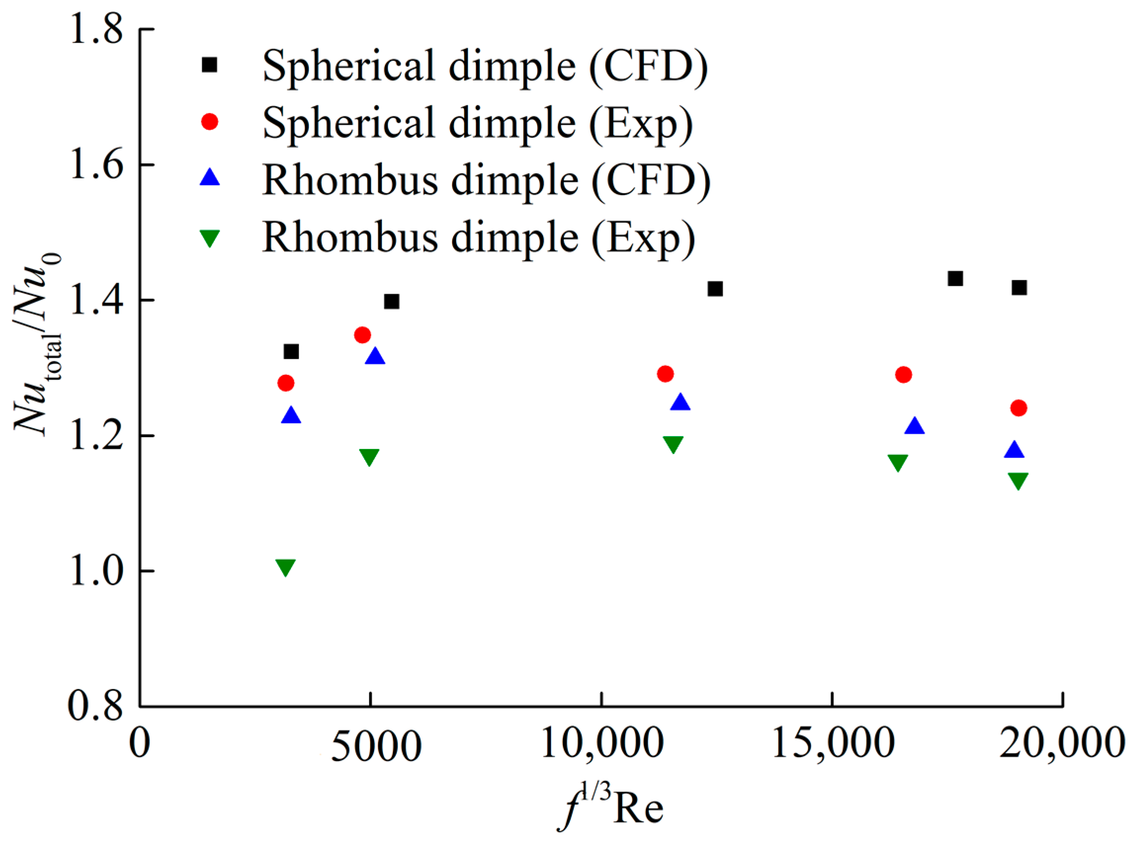
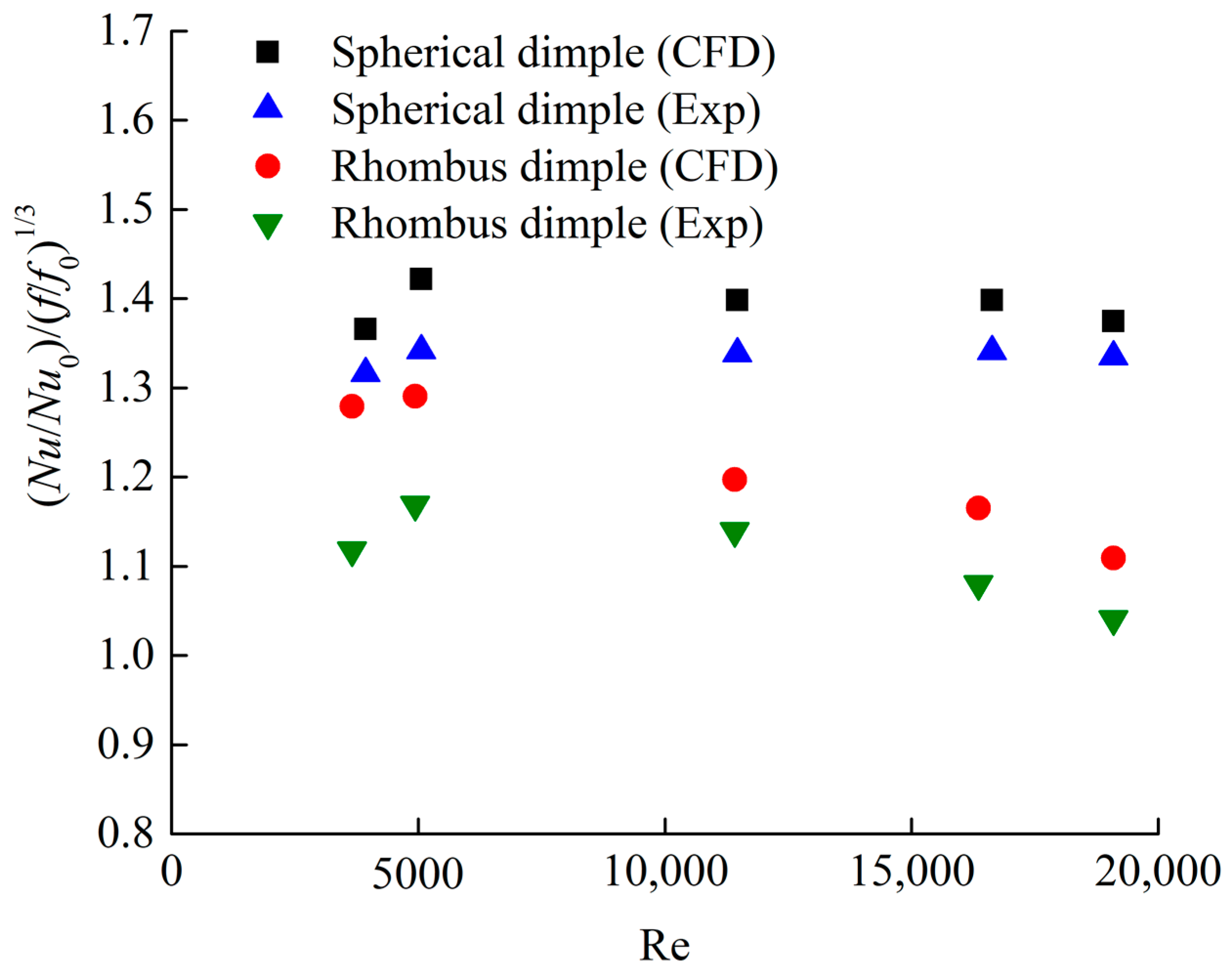
The Nusselt number enhancement of the hemispherical dimple channel increases with the increasing of Reynolds number. The Nusselt number enhancement of a hemispherical dimpled channel with higher radius–depth ratio is noticed to be more than the rhombus dimpled channel.
(2)
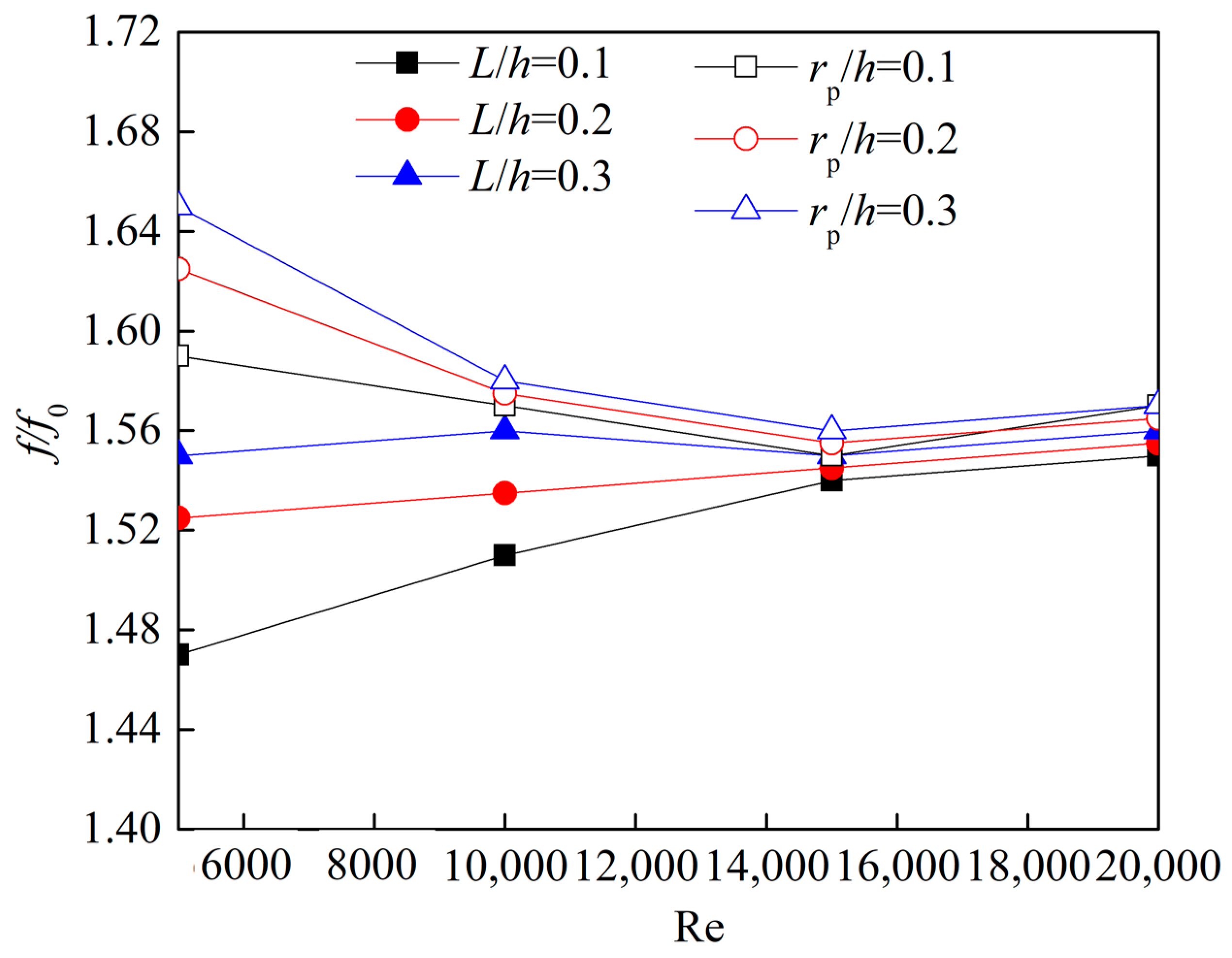
The flow friction performance depends on the dimple radius depth ratio of hemispherical dimple channels. The friction coefficient increment of hemispherical dimple channel increases with increasing of the dimple radius depth ratio, but it decreases with the increase of Reynolds number.
(3)
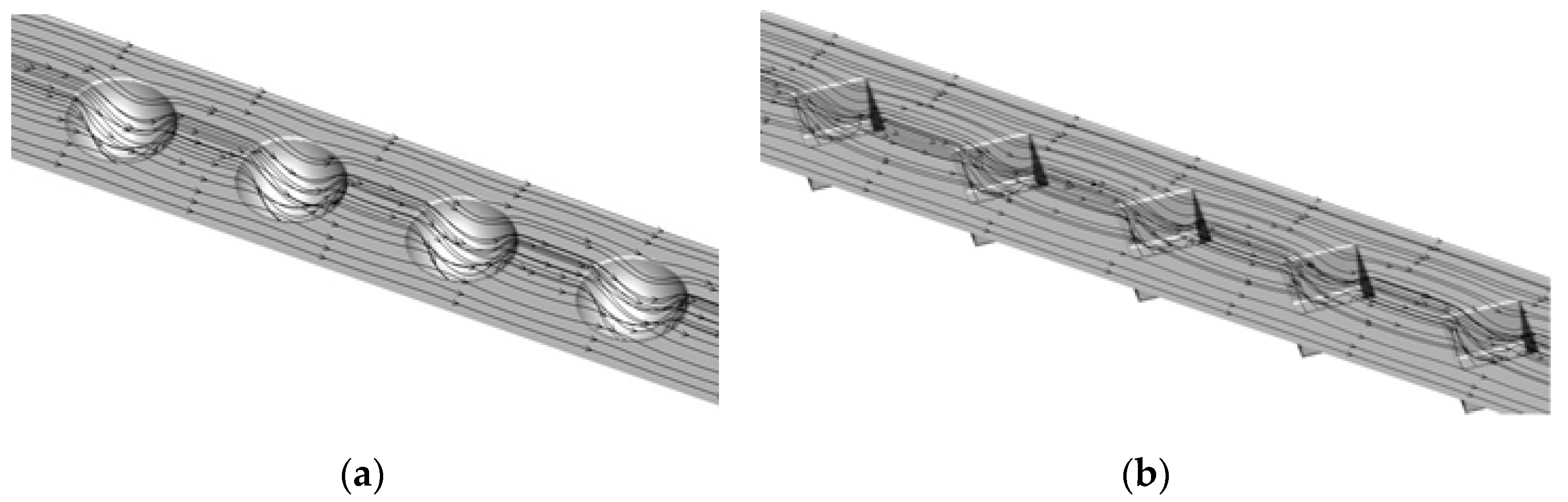
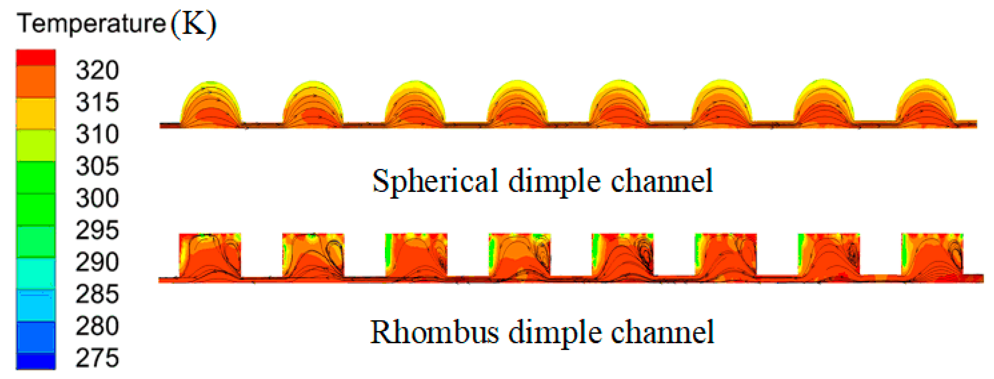
The fluid flows smoothly and easily on the hemispherical dimple surface, and the hemispherical dimples can improve the flow mixing, interrupt the boundary layer and forms periodic impinge flows, thus realized the enhancement of thermal–hydraulic performance.
(4)
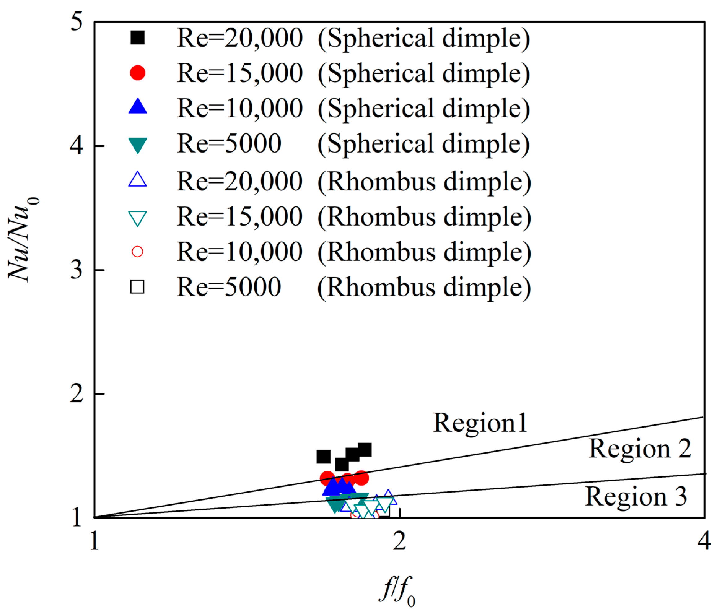
The hemispherical dimpled channel present better overall thermal performance because the strength and extent of the recirculation flow is significant decreased compared with the rhombus dimpled channel.

Author Contributions

Conceptualization, H.T. and Y.H.; methodology, H.T.; software, H.T.; validation, H.T.; formal analysis, H.T.; investigation, P.Y.; resources, H.T.; data curation, Y.H.; writing—original draft preparation, Y.H.; writing—review and editing, P.Y.; visualization, P.Y.; supervision, P.Y.; project administration, H.T.; funding acquisition, H.T. and Y.R.; All authors have read and agreed to the published version of the manuscript.

Funding

This research was funded by the National Natural Science Foundation of China (NSFC), grant number 51805376; the ZheJiang Provincial Natural Science Foundation of China grant number LY20E050028.

Institutional Review Board Statement

Not applicable.

Informed Consent Statement

Not applicable.

Data Availability Statement

Not applicable.

Conflicts of Interest

The authors declare no conflict of interest.

Abbreviations

pFluid pressurePa
viFluid velocitym/s
ρFluid propertykg/m3
FBody forceN
cpSpecific heatJ/(kg·K)
λThermal conductivityW/(m·K)
τTimems
μOil viscosityPa·s
i,j,wDirection of coordinate-
μtTurbulent viscosity ratio-
σkTurbulent kinetic energyK
kTurbulent kinetic energy ratio-
GkTurbulent viscosity-
εDissipation rate-
mtestMass flow rate measurementkg/s
Twwall temperature °C
QTotal heat absorbed by heat transfer fluidJ
moutOutlet mass flow ratekg/s
dChannel diametermm
ReReynold number-
TinInlet temperature°C
AFlow aream2
TaveAverage fluid temperature°C
Q ˙ Heat transfer rateW
ToutOutlet temperature°C
qmHeat fluxW/m2
TmMean temperature difference°C
deEquivalent diameter of channelmm
LChannel lengthmm
fFriction factor-
pPressure difference between inlet and outletPa
Nu0Nusselt number in the fully developed fluid region-
f0Darcy friction factor in the corresponding fully developed fluid region-
PrPrandtl number-
ΦTemperature measurement°C
QhHeat exchange rate of hydraulic oilW/(m2·K)
QcHeat exchange rate of waterW/(m2·K)
mhHeat fluid masskg/s
phHeat fluid densitykg/m3
A0Initial heating aream2
ThiOil inlet temperature°C
ThoOil exit temperature°C
TciInlet exit temperature of cold water°C
TcoExit temperature of cold water°C
xMeasurement-
xavMean of a set of measurements-
ψDeviation-
NutotalTotal Nusselt number-
AwetTotal wetted heat aream2
AbaseBase heating aream2

References

  1. Zhang, J.H.; Li, Y.; Xu, B.; Pan, M.; Chao, Q. Experimental study of an insert and its influences on churning losses in a high-speed electro-hydrostatic actuator pump of an aircraft. Chin. J. Aeronaut. 2019, 32, 2028–2036. [Google Scholar] [CrossRef]
  2. Ashif, P.; Shreyak, K.; Rakesh, K. Forced convection based heat transfer analysis of spherical dimple and protrusion surface in turbulent flow. Trans. Can. Soc. Mech. Eng. 2017, 41, 771–786. [Google Scholar]
  3. Wang, Y.; He, Y.L.; Lei, Y.G.; Zhang, J. Heat transfer and hydrodynamics analysis of a novel dimpled tube. Exp. Therm. Fluid Sci. 2010, 34, 1273–1281. [Google Scholar] [CrossRef]
  4. Bi, C.; Tang, G.H.; Tao, W.Q. Heat transfer enhancement in mini-channel heat sinks with dimples and cylindrical grooves. Appl. Therm. Eng. 2013, 55, 121–132. [Google Scholar] [CrossRef]
  5. Xie, S.; Liang, Z.; Zhang, L.; Wang, Y.; Ding, H.; Zhang, J. Numerical investigation on heat transfer performance and flow characteristics in enhanced tube with dimples and protrusions. Int. J. Heat Mass Transf. 2018, 122, 602–613. [Google Scholar] [CrossRef]
  6. Wang, Y.; He, Y.; Lei, Y.; Li, R. Heat transfer and friction characteristics for turbulent flow of dimpled tubes. Chem. Eng. Technol. 2009, 32, 956–963. [Google Scholar] [CrossRef]
  7. Chang, S.W.; Chiang, K.F.; Chou, T.C. Heat transfer and pressure drop in hexagonal ducts with surface dimples. Exp. Thermal Fluid Sci. 2010, 34, 1172–1181. [Google Scholar] [CrossRef]
  8. Zheng, N.; Liu, W.; Liu, Z.; Liu, P.; Shan, F. A numerical study on heat transfer enhancement and the flow structure in a heat exchanger tube with discrete double inclined ribs. Appl. Therm. Eng. 2015, 90, 232–241. [Google Scholar] [CrossRef]
  9. Wei, X.J.; Joshi, Y.K.; Ligrani, P.M. Numerical simulation of flow and heat transfer inside a micro-channel with one dimpled surface. In Proceedings of the ASME 2002 International Mechanical Engineering Congress and Exposition, New York, NY, USA, 1–2 March 2007; pp. 149–156. [Google Scholar]
  10. Suvanjan, B. Fluid flow and heat transfer in a heat exchanger channel with shortlength twisted tape turbulator inserts. Iran J. Sci. Technol. Trans. Mech. Eng. 2020, 44, 217–227. [Google Scholar]
  11. Afanasyev, V.N.; Chudnovsky, Y.P.; Leontiev, A.I.; Roganov, P.S. Turbulent flow friction and heat transfer characteristics for spherical cavities on a flat plate. Exp. Therm. Fluid Sci. 1993, 7, 1–8. [Google Scholar] [CrossRef]
  12. Bunker, R.S.; Donnellan, K.F. Heat transfer and friction factors for flows inside circular tubes with concavity surfaces. J. Turbomach. 2003, 125, 665–670. [Google Scholar] [CrossRef]
  13. Coy, E.B.; Danczyz, S.A. Measurements of the effectiveness of concave spherical dimples for enhancement heat transfer. J. Propuls. Power 2011, 27, 955–958. [Google Scholar] [CrossRef]
  14. Rao, Y.; Li, B.; Feng, Y. Heat transfer of turbulent flow over surfaces with spherical dimples and teardrop dimples. Exp. Therm. Fluid Sci. 2015, 61, 201–209. [Google Scholar] [CrossRef]
  15. Turnow, J.; Kornev, N.; Zhdanov, V.; Hassel, E. Flow structures and heat transfer on dimples in a staggered arrangement. Int. J. Heat Fluid Flow 2012, 35, 168–175. [Google Scholar] [CrossRef]
  16. Turnow, J.; Kornev, N.; Isaev, S.; Hassel, E. Vortex mechanism of heat transfer enhancement in a channel with spherical and oval dimples. Heat Mass Transf. 2011, 47, 301–313. [Google Scholar] [CrossRef]
  17. Xie, G.; Liu, J.; Ligrani, P.M.; Zhang, W.H. Numerical analysis of flow structure and heat transfer characteristics in square channels with different internal-protruded dimple geometries. Int. J. Heat Mass Transf. 2013, 67, 81–97. [Google Scholar] [CrossRef]
  18. Shchukin, A.V.; Il’inkov, A.V.; Takmovtsev, V.V.; Khabibullin, I.I. Specifics of heat and mass transfer in spherical dimples under the effect of external factors. Therm. Eng. 2017, 64, 450–457. [Google Scholar] [CrossRef]
  19. Leontiev, A.I.; Kiselev, N.A.; Burtsev, S.A.; Strongin, M.M.; Vinogradov, Y.A. Experimental investigation of heat transfer and drag on surfaces with spherical dimples. Exp. Therm. Fluid Sci. 2016, 79, 74–84. [Google Scholar] [CrossRef]
  20. Zhou, F.; Acharya, S. Experimental and computational study of heat/mass transfer and flow structure for four dimple shapes in a square internal passage. J. Turbomach. 2012, 136, 061028. [Google Scholar]
  21. Isaev, S.A.; Leont’ev, A.I.; Baranov, P.A. Simulating tornado-like enhancement of heat transfer for low-velocity motion of air in a rectangular channel with cavities. Part 1: Selection and justification of calculation methods. Therm. Eng. 2007, 54, 193–199. [Google Scholar] [CrossRef]
  22. Isaev, S.A.; Leont’ev, A.I.; Baranov, P.A. Simulating tornado-like enhancement of heat transfer under low-velocity motion of air in a rectangular dimpled channel. Part 2: Results of parametric studies. Therm. Eng. 2007, 54, 655–663. [Google Scholar] [CrossRef]
  23. Kim, K.Y.; Moon, M.A.; Kim, H.M. Shape optimization of inclined elliptic dimples in a cooling channel. J. Thermophys. Heat Transf. 2011, 25, 472–476. [Google Scholar] [CrossRef]
  24. Yoon, H.S.; Park, S.H.; Choi, C.; Ha, M.Y. Numerical study on characteristics of flow and heat transfer in a cooling passage with a tear-drop dimple surface. Int. J. Therm. Sci. 2015, 89, 121–135. [Google Scholar] [CrossRef]
  25. Park, J.; Ligrani, P.M. Numerical predictions of heat transfer and fluid flow characteristics for seven different dimpled surfaces in a channel. Numer. Heat Transf. Part A Appl. 2005, 47, 209–232. [Google Scholar] [CrossRef]
  26. Ge, M.W.; Xu, C.X.; Cui, G.X. Study on flow structures due to a dimple in channel flow by direct numerical simulation. Int. J. Flow Control 2013, 4, 67–82. [Google Scholar] [CrossRef]
  27. Lan, J.; Xie, Y.; Zhang, D. Flow and heat transfer in microchannels with dimples and protrusions. J. Heat Transf. 2012, 134, 021901. [Google Scholar] [CrossRef]
  28. Haque, M.R.; Rahman, M.A. Numerical investigation of convective heat transfer characteristics of circular and oval tube banks with vortex generators. J. Mech. Sci. Technol. 2020, 34, 457–467. [Google Scholar] [CrossRef]
  29. Xie, S.; Liang, Z.; Zhang, L.; Wang, Y. A numerical study on heat transfer enhancement and flow structure in enhanced tube with cross ellipsoidal dimples. Int. J. Heat Mass Transf. 2018, 125, 434–444. [Google Scholar] [CrossRef]
  30. Xie, S.; Liang, Z.; Zhang, J.; Zhang, L.; Wang, Y.L.; Ding, H. Numerical investigation on flow and heat transfer in dimpled tube with teardrop dimples. Int. J. Heat Mass Transf. 2019, 131, 713–723. [Google Scholar] [CrossRef]
  31. Zhang, F.; Wang, X.J.; Li, J. Flow and heat transfer characteristics in rectangular channels using combination of convex-dimples with grooves. Appl. Therm. Eng. 2017, 113, 926–936. [Google Scholar] [CrossRef]
  32. Kaood, A.; Abou-Deif, T.; Eltahan, H.; Yehia, M.; Khalil, E. Numerical investigation of heat transfer and friction characteristics for turbulent flow in various corrugated tubes. Proc. Inst. Mech. Eng. Part A J. Power Energy 2018, 233, 457–475. [Google Scholar] [CrossRef]
  33. Gnielinski, V. New equations for heat and mass transfer in turbulent pipe and channel flow. Int. Chem. Eng. 1976, 16, 359–368. [Google Scholar]
  34. Rao, Y.; Feng, Y.; Li, B.; Weigand, B. Experimental and numerical study of heat transfer and flow friction in channels with dimples of different shapes. J. Heat Transf. 2015, 37, 031901. [Google Scholar] [CrossRef]
  35. Bergman, T.; Lavine, A.; Incropera, F.K.; Dewitt, D.P. Fundamentals of Heat and Mass Transfer, 7th ed.; Wiley: Hoboken, NJ, USA, 2011; pp. 256–279. [Google Scholar]
  36. Gee, D.L.; Webb, R.L. Forced Convection Heat Transfer in Helically Rib-Roughened Tubes. Int. J. Heat Mass Transf. 1980, 23, 1127–1136. [Google Scholar] [CrossRef]
  37. Fan, J.F.; Ding, W.K.; He, Y.L.; Tao, W.Q. Three-dimensional numerical study of fluid and heat transfer characteristics of dimpled fin surfaces. Numer. Heat Transf. Part A Appl. 2012, 62, 271–294. [Google Scholar] [CrossRef]
Figure 1. Computational domain of a channel with different dimples.
Machines 09 00072 g001
Figure 2. A dimpled channel model with boundary conditions.
Machines 09 00072 g002
Figure 3. Grid structure of different dimples. (a) Hemispherical dimple. (b) Rhombus dimple.
Machines 09 00072 g003
Figure 4. Grid parameters.
Machines 09 00072 g004
Figure 5. Grid independence check.
Machines 09 00072 g005
Figure 6. Test rig established at Wenzhou University. (a) Schematic of the experimental system. (b) Photographs of the test rig.
Machines 09 00072 g006
Figure 7. Comparison of the numerical results and the experimental data. (a) Hemispherical dimple. (b) Rhombus dimple.
Machines 09 00072 g007
Figure 8. Comparisons of numerical results of Nusselt number with the date from Gnielinski [33] correlation.
Machines 09 00072 g008
Figure 9. Comparisons of numerical results of friction factor with the data from Filonenko correlation.
Machines 09 00072 g009
Figure 10. Nusselt numbers of the dimpled channels.
Machines 09 00072 g010
Figure 11. Heat transfer enhancement of the dimpled channels.
Machines 09 00072 g011
Figure 12. Nusselt numbers on the dimpled surfaces under different Reynolds numbers. (a) Re = 3000. (b) Re = 20,000.
Machines 09 00072 g012
Figure 13. The CFD results of Nusselt number along the flow direction of different dimpled channels.
Machines 09 00072 g013
Figure 14. The streamlines in a near-wall channel with a distance of 0.3 mm away from the endwall. (a) Hemispherical dimple. (b) Rhombus dimple.
Machines 09 00072 g014
Figure 15. Effect of Reynolds number on heat transfer enhancement factor for different dimpled channel.
Machines 09 00072 g015
Figure 16. Effect of Reynolds number on friction factor increment for different dimpled channel.
Machines 09 00072 g016
Figure 17. Comparisons of fluid temperature over the different dimpled channel Re = 10,000.
Machines 09 00072 g017
Figure 18. Comparisons of overall thermal performance of the dimpled channels.
Machines 09 00072 g018
Figure 19. The overall thermal performance of different dimpled channels considering the effect of the Reynolds number.
Machines 09 00072 g019
Figure 20. Performance evaluation plot of different dimpled channel.
Machines 09 00072 g020
Table 1. The effect of mesh sizes on the Nusselt number and pressure difference.
Grid Numberpp-Difference, %NμNμ-Difference, %
468222712.361323.131.725
532522461.235322.91.652
96342227.60.406322.491.523
20,4882222.10.017320.350.094
28,3202218.61Reference317.65Reference
Table 2. Tested parameters and instruments.
Measured ParametersInstrumentsBrandErrorMeasuring Range
Oil temperatureRTDPT100±0.05%FS0–200 °C
Tube wall and water temperatureThermocoupleOMEGA±0.05%FS0–200 °C
Pressure differenceDifferential pressure transmitterABB±0.04%FS0–1000 Pa
Oil volume flow rateVolumetric flowmeterABB±0.2%FS0–2000 m3/h
Water mass flow rateElectromagnetic flow meterABB±0.25%FS0–4 m3/h
Table 3. Experimental uncertainties expressed by average deviation.
ParametersDeviation
Tin3.9 K
Tout1.5 K
Tci3.6 K
Tco1.5 K
Tm3.7 K
Pressure drop25 bar
Table 4. Comparison of heat exchange rate of hydraulic oil and water in heat exchanger.
RehRecQh (W)Qc (W)Difference (%)
750027201287.51201.36.7
39201906.21879.51.4
10,50027202518.32447.82.8
39203176.83125.91.6
52133765.23723.81.1
78364782.14676.92.2
15,00039203931.53829.32.6
52135375.75273.61.9
78365872.35737.22.3
10,9806473.46330.92.2
17,50027203495.23388.72.7
52135162.45037.52.4
Publisher’s Note: MDPI stays neutral with regard to jurisdictional claims in published maps and institutional affiliations.

