Communication

Position Estimation of a Two-Phase Switched Reluctance Motor at Standstill

1
Graduate School of Nano IT Design Fusion, Seoul National University of Science and Technology, Seoul 01811, Korea
2
Medical Accelerator Research Team, Department of RI Application, Korea Institute of Radiological & Medical Sciences (KIRAMS), Seoul 01812, Korea
*
Authors to whom correspondence should be addressed.
Machines 2021, 9(12), 359; https://doi.org/10.3390/machines9120359
Submission received: 8 November 2021 / Revised: 7 December 2021 / Accepted: 13 December 2021 / Published: 16 December 2021
(This article belongs to the Section Electrical Machines and Drives)

Abstract

:
In this paper, a sensorless position detection method of a two-phase switched reluctance motor (SRM) at standstill is proposed based on the voltage pulse injection method. Due to the torque dead zone and the lack of starting capability in the two-phase SRM, a rotor with a stepped structure is adopted to ensure continuous torque generation. The inductance characteristics of the asymmetric SRM are analyzed, and the region of the rotor position is categorized into linear regions and nonlinear regions with several key rotor positions and threshold values of self-inductance. A simple analytical model of the phase self-inductance profile of the asymmetric rotor SRM is proposed, which only requires a few linear equations, to replace the conventional look-up table. A pulse injection-based position estimation method is proposed based on the aforementioned analytical model. Short voltage pulses are injected into both phases at the same time to determine the position where the rotor is actually located at standstill. The proposed position detection method is simple and requires no extra circuitry. The simulation results are given and show the proposed estimation method can acquire a precise rotor position accurately at a standstill condition.

1. Introduction

A switched reluctance motor (SRM) has attractive features such as a robust rotor structure and a wide speed range, which endow it with strong competitiveness against conventional AC motors in a variety of applications, especially in harsh environments and high-speed operation conditions [1,2,3].
Information on the rotor position is inherently needed for an SRM to perform an excitation on each phase properly due to the unique torque generating mechanism of the motor. However, the adoption of a physical position sensor reduces the reliability and increases the cost of the motor drive because the sensor may malfunction in harsh environments. Hence, multiple position sensorless control methods of SRMs have been proposed by scholars to exclude the adoption of position sensors [4,5,6]. In [7], various existing sensorless control schemes of an SRM drive were reviewed and broadly classified into a hardware-intensive method, a data-intensive method, and a model-based method. Generally, most of these sensorless methods are based on knowledge of the magnetic characteristics of the motor. A voltage signal injection is one of those methods that are popularly used in sensorless controls in various types of motors [8,9,10]. The pulse injection method in an SRM is particularly simple.
By using an incremental encoder, the rotor position cannot be obtained when the motor is not rotating. Therefore, in those applications, an initial alignment is needed by exciting one phase for motor starting to park the rotor at a known aligned position. However, the alignment process is not quick enough, especially with large rotor inertia, and the rotor jerks back and forth before it finally becomes stationary. This negative effect is known as starting hesitation, which hinders the motor to start rapidly [11]. Knowing the rotor position at standstill is necessary for an effective start of the motor and the avoidance of starting hesitation. In [12], three-phase bipolar square wave signals were injected into the windings of a planar SRM to achieve an initial translator position estimation. By recording the response current from the zero crossing point to the peak point, the flux linkage could be derived and the initial mover position could be estimated. In [13], a highly reliable SRM starting scheme was proposed using a set of pulse injection-based position estimation algorithms at different stages of starting. This synthetic starting scheme included a double inductance dynamic threshold-based method, a phase inductance pairwise comparison-based method, and a position index pulse estimation method based on the idle phase inductance threshold.
The effective modeling of the magnetic characteristics is a crucial step in the pulse injection-based sensorless method. In [14], a linear inductance model was used for a position estimation at standstill. The calculation of the rotor position was not affected by the variation of the DC link voltage and duration of the voltage pulse by using the peak current from two phases. A quadratic polynomial interpolation was used to model the peak current vs. the rotor position at standstill for SRMs in light electric vehicle applications in [11]. In [15], a cubic spline function was used for the modeling instead. However, all these methods only work for certain SRM topologies; they are not suitable for use in special cases such as motors with an asymmetric structure, e.g., a two-phase SRM with an asymmetric rotor, which is the objective of the study in this paper. Therefore, modeling of the asymmetric inductance profile is required to develop the position estimation method. In [16], a sensorless control at standstill was proposed to judge the starting phase based on a comparison of the injected current in each phase. However, the method was only able to determine an approximate range instead of detecting the precise rotor position.
In this paper, a pulse injection-based position estimation method of a two-phase SRM at standstill is proposed. The rotor of the two-phase SRM is specially designed with asymmetric rotor poles to ensure a one direction starting capability at any rotor position. An analytical model of the two-phase asymmetric SRM is proposed using linear functions based on the unique fact that parts of the rising region of the unsaturated phase self-inductance profile of the two-phase SRM is piecewise linear. The model is fairly easy to obtain and the need for the usage of a conventional look-up table can be eliminated. A position estimation algorithm is proposed utilizing several key rotor positions that separate the linear and nonlinear regions and also utilize two distinct self-inductance thresholds. Short voltage pulses with a constant duration are injected into the two phases to determine the rotor position. A simulation is carried out in a MATLAB/Simulink environment and the results show that the proposed position estimation method can acquire a precise rotor position with sufficient accuracy.

2. Proposed Position Estimation Method at Standstill

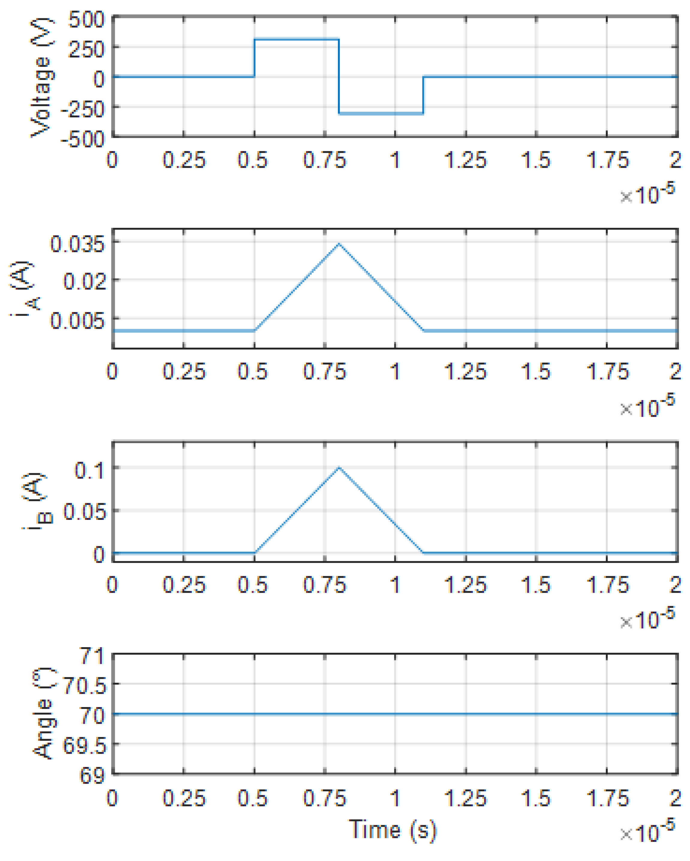
2.1. Principle of the Pulse Injection Method

Among the various position sensorless control schemes, pulse injection is a popular method that can be applied to a wide speed range.
The voltage equation of a phase of an SRM is given as:
u = R i + d ψ ( θ , i ) d t
where u is the phase voltage, R is the phase resistance, i is the phase current, ψ is the phase flux linkage, and θ is the rotor position.
The flux linkage can be expressed as:
ψ ( θ , i ) = L ( θ , i ) i
where L is the phase self-inductance.
Due to the doubly-salient magnetic structure, the self-inductance of an SRM varies with the rotor position. An SRM regularly operates under deep saturation conditions; the self-inductance is also related to the current.
By substituting Equation (2) into Equation (1), Equation (1) can be derived as:
u = R i + d L ( θ , i ) i d t = R i + [ L ( θ , i ) + L ( θ , i ) i ] d i d t + i L ( θ , i ) θ ω
where ω is the rotational speed.
By injecting short voltage pulses into the phase winding at a standstill condition when no rated current for torque generation flows, the generated current by the voltage pulses are small, which leads to u R i . The resistive voltage term R i can then be omitted from Equation (3). If the magnetic circuit is unsaturated, the self-inductance will be irrelevant to the current and the term L ( θ , i ) i in Equation (3) can thus be neglected. Further, at a standstill condition, the back EMF term i L ( θ , i ) θ ω is zero. Considering the above, Equation (3) becomes:
u = L ( θ ) d i d t .
It can be easily found that the current increases linearly with the short voltage pulse applied, as shown in Figure 1. The current reached the peak immediately after the positive voltage pulse is applied and the peak current can be expressed as:
i p k = U d c Δ t L ( θ )
where i p k is the peak current, U d c is the DC link voltage, and Δ t is the duration of the positive voltage pulse.
Thus, based on Equation (5), the self-inductance can be obtained by measuring the peak current. The rotor position is then available if the relationship between L and θ is known, which can be obtained from the FEM analysis.

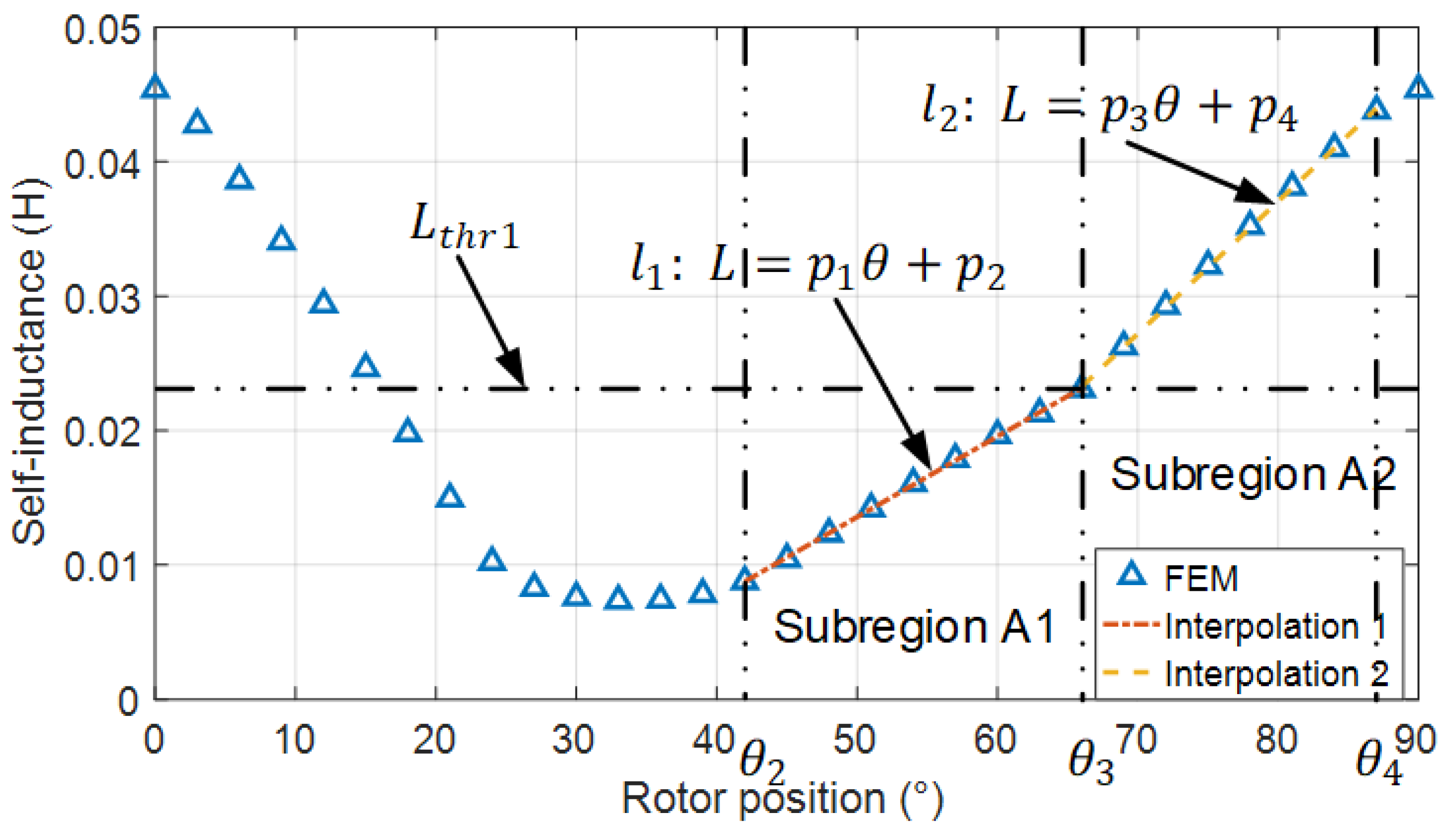
2.2. Inductance Model of a Two-Phase SRM with a Stepped Rotor

Considering a one-way rotation of the motor compared with an SRM with three phases or a higher number of phases, a two-phase SRM with a conventional symmetric rotor suffers from discontinuous torque generation caused by a torque dead zone [17]. Even with an excitation current present, there is very little positive torque generated within the torque dead zone. Thus, the two-phase SRM lacks the capability of self-starting at all rotor positions for a one-way rotation.
An asymmetric stepped rotor was used to overcome the self-starting problem of a two-phase SRM, as shown in Figure 2. The stepped rotor featured an asymmetric rotor pole and a stepped airgap. The rotor pole was divided into two parts with a different radius. This increased the length of the self-inductance rising region, which is used to generate positive torque. Therefore, the positive torque generating regions of the two phases overlapped and the torque dead zone was eliminated.
A two-phase SRM with a stepped rotor was designed for an axial flow fan application. The motor was capable of producing 1 hp of power at a rated speed of 5500 rpm. The specifications and geometry parameters are listed in Table 1.
The self-inductance profile of each phase obtained by the FEM analysis is shown in Figure 3. By looking at phase A, with the asymmetric design of the rotor, the self-inductance profile was no longer symmetrical. The self-inductance rising region (34–90 degrees for phase A) took up 62% of the total region (0–90 degrees, one mechanical cycle) using the stepped rotor compared with only 50% in the conventional symmetric rotor, which indicated that the torque generative region (self-inductance rising region) of one phase was extremely stretched.
Another noteworthy feature of the self-inductance profile of the two-phase motor was that, due to the nonuniform stepped airgap, there were two linearly increasing regions of the self-inductance profile with different slopes in each phase. These were denoted as Subregion A1 (42–66 degrees) and Subregion A2 (66–87 degrees) of phase A, and Subregion B1 and Subregion B2 of phase B, as shown in Figure 3. θ 1 is the rotor position at the self-inductance slope turning point of phase B between Subregion B1 and Subregion B2. θ 2 is the rotor position where Subregion B2 ended or Subregion A1 started. θ 3 is the rotor position between Subregion A1 and Subregion A2. θ 4 is the rotor position where Subregion A2 ended or Subregion B1 started. The Subregions A1 and A2 were used as the torque generative region of phase A. Similarly, the Subregions B1 and B2 were used to generate the motor torque in phase B. It should be noted that although Region A (a combination of Subregions A1 and A2) and Region B were called the torque generative region, there was only a small position sensing current generated by the injected voltage pulses at standstill before the motor starting up. The self-inductance of phase A at the slope turning point between the two Subregions A1 and A2 was denoted by L t h r 1 . Thus, a linear interpolation could be used to model the two specific subregions of the self-inductance profile. The complex nonlinear parts in the self-inductance rising region, i.e., 34–42 degrees and 87–90 degrees in phase A, could be ignored because they were not used for the position estimation. The self-inductance of phase A within the Subregions A1 and A2 could be approximated as:
L A ( θ ) = { p 1 θ + p 2 ,               θ 2 θ < θ 3 p 3 θ + p 4 ,               θ 3 θ < θ 4
where p 1 , p 2 , p 3 , and p 4 were the coefficients.
By using the FEM data, interpolations were carried out and shown in Figure 4. The interpolation curves matched the FEM data quite well. The values of p 1 , p 2 , p 3 , and p 4 were 0.0006, −0.0164, 0.0010, and −0.0417, respectively. It was obvious that the slopes of the two subregions had a clear difference.
In order to take advantage of the linearity, the proposed position estimation method used only the linear self-inductance segments to calculate the rotor position. The peak current of phase A was used to calculate the rotor position in Region A whereas phase B was used instead in Region B, thus covering the full mechanical cycle (0–90 degrees).
Similarly, the self-inductance of phase B in its linear subregions was given as:
L B ( θ ) = { p 1 ( θ + 45 ° ) + p 2 , 0 ° θ < θ 1 , θ 4 θ < 90 ° p 3 ( θ + 45 ° ) + p 4 , θ 1 θ < θ 2
Therefore, for the different regions, the rotor position could be obtained from Equation (6) and Equation (7) as:
θ = { ( L B p 2 ) / p 1 45 ° ,           0 ° θ < θ 1 ( L B p 4 ) / p 3 45 ° ,           θ 1 θ < θ 2 ( L A p 2 ) / p 1 ,                                     θ 2 θ < θ 3 ( L A p 4 ) / p 3 ,                                     θ 3 θ < θ 4 ( L B p 2 ) / p 1 45 ° ,       θ 4 θ < 90 °

2.3. Region Judgement and Position Estimation

In order to properly estimate the rotor position, the region where the rotor is actually at should be determined. However, when injecting the voltage pulse into only one phase, there is not enough information to determine the rotor position due to the self-inductance. The rotor position does not exhibit one-to-one mapping and the same value of self-inductance could lead to two different rotor positions in either the rising region or the falling region of the self-inductance profile. Therefore, the voltage pulse should be injected into both phases.
In order to know the exact region (Region A or B, defined in Figure 3) where the rotor was at, the utilization of the self-inductance trajectory ( L A , L B ) was proposed, as shown in Figure 5 where Region A was denoted by triangle marks and Region B was denoted by cross marks. The plane was divided into four areas, I, II, III, and IV, by a dashed line. The threshold L t h r 2 was the self-inductance at the rotor position where the self-inductance of phase A was equal to that of phase B. By comparing the actual self-inductance with the threshold L t h r 2 , the trajectory could be confined within only two areas (I and II, or III and IV). It was easily observed that there was a line m 1 in between I and II that separated the two areas and another line m 2 separated the Area III and Area IV. The equation of m 1 and m 2 could be easily calculated by the two point form equation of a line. One point was the cross point shown in Figure 5; the other point was the separation point between Region A and Region B. Thus, by finding out whether the trajectory was above or below the specific line, the area could be determined. Further, the region could also be determined.
The detailed process to determine the region and calculate the rotor position is given as follows.
(1) Inject the voltage pulse with a short duration of Δ t into phase A and phase B.
(2) Measures the peak current i p k A and i p k B .
(3) Calculate the self-inductance L A and L B by using Equation (5).
(4) Determine in which area (Area I, II, III, or IV) the self-inductance trajectory ( L A , L B ) is located by using the threshold L t h r 2 and two line equations, m 1 :   y = k 1 x + k 2 and m 2 :   y = k 3 x + k 4 , as shown in Figure 5.
(5) Determine which region (Region A or B) is the rotor.
(6) Determine the linear subregion by using threshold L t h r 1 .
(7) Estimate the rotor position by using the interpolated line equation l 1 or l 2 .
The detailed flow chart of the proposed rotor position estimation method is shown in Figure 6.

3. Simulation Results and Discussion

In order to verify the proposed position estimation method at standstill, a simulation model was built in MATLAB/Simulink. The simulations were performed when the rotor parked at different rotor positions. The DC link voltage was 310 V. Voltage pulses were applied to each phase.
At 55 degrees, which was inside Subregion A, the simulation result can be seen in Figure 7. The peak current of phase A and phase B was 0.056 A and 0.029 A, respectively. The self-inductances calculated from Equation (5) were 0.0166 H and 0.0321 H for phase A and phase B, respectively. From Figure 5, the area was judged to be II and the region was determined to be Subregion A1. Thus, the rotor was located at the region where the self-inductance of phase A was linear. The self-inductance of phase A was then used to calculate the rotor position by Equation (6) and the result was 55.06 degrees; the estimation error was only 0.06 degrees.
Figure 8 shows the results at 70 degrees. The peak currents of phase A and phase B were 0.034 A and 0.1 A, respectively. The self-inductances of phase A and phase B calculated were 0.0274 H and 0.0093 H, respectively. The self-inductance could be found located in Area III and the rotor was in Subregion A2. The self-inductance of phase A was then used to calculate the rotor position and the estimated value was 70.14 degrees, which had only a 0.14 degree error.
The position estimation result at different angles and the actual rotor position in one mechanical cycle are shown and compared in Figure 9. The estimation errors at different angles are shown in Figure 10. It could be seen that the maximum estimation error was less than 0.2 degrees, which proved that the proposed method was effective at different rotor positions and the estimated rotor position was sufficiently accurate.

4. Conclusions

In this paper, we developed a position estimation method for a two-phase SRM at standstill based on a pulse injection. The two-phase SRM featured a stepped airgap to eliminate the torque dead zone and ensure continuous torque generation. By performing an FEM analysis, the self-inductance characteristics of the asymmetric two-phase SRM were obtained. It was found that the linear parts of the self-inductance rising region could be divided into two linear subregions with different slopes and the nonlinear parts could be ignored. Based on this fact, a simple analytical model was proposed for the self-inductance profile using piecewise linear functions. A position estimation method at standstill was proposed; the method injected short voltage pulses into all the phases to determine the region where the rotor was located and the phase for the position detection. For a given duration of the voltage pulse, the peak current was inversely proportional to the phase self-inductance. The rotor position could then be obtained via a self-inductance estimation. By using the proposed self-inductance model, the rotor position could be estimated instead of using a conventional look-up table. The simulation results showed that the proposed method could estimate the rotor position accurately at standstill.

Author Contributions

Conceptualization, J.F.; methodology, J.F.; investigation, J.F.; writing—original draft preparation, J.F.; supervision, I.J. and Y.L. All authors have read and agreed to the published version of the manuscript.

Funding

This study was supported by the Seoul National University of Science and Technology and supported by a grant from the Korea Institute of Radiological and Medical Sciences (KIRAMS), funded by Ministry of Science and ICT (MSIT), Republic of Korea (No.50538-2021).

Institutional Review Board Statement

Not applicable.

Informed Consent Statement

Not applicable.

Data Availability Statement

Not applicable.

Acknowledgments

We acknowledge the support of the Seoul National University of Science and Technology and the Korea Institute of Radiological and Medical Sciences (KIRAMS).

Conflicts of Interest

The authors declare no conflict of interest.

References

  1. Chiang, C.; Hsieh, M.; Li, Y.; Tsai, M. Impact of Electrical Steel Punching Process on the Performance of Switched Reluctance Motors. IEEE Trans. Magn. 2015, 51, 8113304. [Google Scholar] [CrossRef]
  2. Choi, J.; Ahn, J.S.; Lee, J. The characteristic analysis of switched reluctance motor considering DC-link Voltage ripple on hard and soft chopping modes. IEEE Trans. Magn. 2005, 41, 4096–4098. [Google Scholar] [CrossRef]
  3. Yang, Z.; Shang, F.; Brown, I.P.; Krishnamurthy, M. Comparative Study of Interior Permanent Magnet, Induction, and Switched Reluctance Motor Drives for EV and HEV Applications. IEEE Trans. Transp. Electrif. 2015, 1, 245–254. [Google Scholar] [CrossRef]
  4. Hudson, C.A.; Lobo, N.S.; Krishnan, R. Sensorless Control of Single Switch-Based Switched Reluctance Motor Drive Using Neural Network. IEEE Trans. Ind. Electron. 2008, 55, 321–329. [Google Scholar] [CrossRef]
  5. Guo, H.J.; Takahashi, M.; Watanabe, T.; Ichinokura, O. A new sensorless drive method of Switched Reluctance Motors based on motor’s magnetic characteristics. IEEE Trans. Magn. 2001, 37, 2831–2833. [Google Scholar] [CrossRef]
  6. Ertugrul, N.; Cheok, A.D. Indirect angle estimation in switched reluctance motor drive using fuzzy logic based motor model. IEEE Trans. Power Electron. 2000, 15, 1029–1044. [Google Scholar] [CrossRef]
  7. Ehsani, M.; Fahimi, B. Elimination of position sensors in switched reluctance motor drives: State of the art and future trends. IEEE Trans. Ind. Electron. 2002, 49, 40–47. [Google Scholar] [CrossRef]
  8. Wu, X.; Feng, Y.; Liu, X.; Huang, S.; Yuan, X.; Gao, J.; Zheng, J. Initial Rotor Position Detection for Sensorless Interior PMSM With Square-Wave Voltage Injection. IEEE Trans. Magn. 2017, 53, 8112104. [Google Scholar] [CrossRef]
  9. Champa, P.; Somsiri, P.; Wipasuramonton, P.; Nakmahachalasint, P. Initial Rotor Position Estimation for Sensorless Brushless DC Drives. IEEE Trans. Ind. Appl. 2009, 45, 1318–1324. [Google Scholar] [CrossRef]
  10. Ofori, E.; Husain, T.; Sozer, Y.; Husain, I. A Pulse-Injection-Based Sensorless Position Estimation Method for a Switched Reluctance Machine Over a Wide Speed Range. IEEE Trans. Ind. Appl. 2015, 51, 3867–3876. [Google Scholar] [CrossRef]
  11. Jamil, M.U.; Kongprawechnon, W.; Chayopitak, N. Eliminating starting hesitation for reliable operation of switched reluctance motor without machine parameters for light electric vehicle applications. IET Electr. Power Appl. 2019, 13, 996–1003. [Google Scholar] [CrossRef]
  12. Sun, J.-D.; Cao, G.-Z.; Qian, Q.-Q. A Novel Initial Mover Position Estimation Method for Planar Switched Reluctance Motors with Bipolar Square-Wave Voltage Injection. In Proceedings of the 2021 13th International Symposium on Linear Drives for Industry Applications (LDIA), Wuhan, China, 1–3 July 2021; pp. 1–5. [Google Scholar]
  13. Cai, J.; Yan, Y.; Zhang, W.; Zhao, X. A Reliable Sensorless Starting Scheme for SRM With Lowered Pulse Injection Current Influences. IEEE Trans. Instrum. Meas. 2021, 70, 1003209. [Google Scholar] [CrossRef]
  14. Kanokvate, T.; Seubsuang, K.; Prapon, J.; Pakasit, S.; Chiba, A.; Tadashi, F. An Improvement on Position Estimation and Start up Operation for Switched Reluctance Motor Drives. In Proceedings of the 2007 IEEE Power Engineering Society General Meeting, Tampa, FL, USA, 24–28 June 2007; pp. 1–6. [Google Scholar]
  15. Trakrancharoungsook, K.; Kittiratsatcha, S. Position Estimation Technique of a Switched Reluctance Motor at Standstill. In Proceedings of the 2007 Power Conversion Conference—Nagoya, Nagoya, Japan, 2–5 April 2007; pp. 264–270. [Google Scholar]
  16. Gao, H.; Salmasi, F.R.; Ehsani, M. Sensorless control of SRM at standstill. In Proceedings of the APEC 2001. Sixteenth Annual IEEE Applied Power Electronics Conference and Exposition, Anaheim, CA, USA, 4–8 March 2001; Volume 2, pp. 850–856. [Google Scholar]
  17. Hieu, P.T.; Lee, D.; Ahn, J. Design of a high speed 4/2 switched reluctance motor for blender application. In Proceedings of the 2017 IEEE Transportation Electrification Conference and Expo, Asia-Pacific (ITEC Asia-Pacific), Harbin, China, 7–10 August 2017; pp. 1–5. [Google Scholar]
Figure 1. Voltage pulse injection.
Machines 09 00359 g001
Figure 2. An SRM with a stepped rotor.
Machines 09 00359 g002
Figure 3. Self-inductance profile of a two-phase SRM.
Machines 09 00359 g003
Figure 4. Result of the interpolation.
Machines 09 00359 g004
Figure 5. Region judgement.
Machines 09 00359 g005
Figure 6. Flow chart of the proposed position estimation method of an SRM at standstill.
Machines 09 00359 g006
Figure 7. Simulation result at 55 degrees.
Machines 09 00359 g007
Figure 8. Simulation result at 70 degrees.
Machines 09 00359 g008
Figure 9. Actual angle vs. the estimated angle.
Machines 09 00359 g009
Figure 10. Error of the position estimation.
Machines 09 00359 g010
Table 1. Parameters of the two-phase SRM.
ParameterValue
Number of stator poles8
Number of rotor poles4
Stator outer radius53 mm
Stator yoke thickness6.5 mm
Rotor outer radius21 mm
Rotor yoke thickness7 mm
Shaft radius10 mm
Stack length55.5 mm
1st airgap0.3 mm
2nd airgap0.4 mm
Stator pole arc23°
Rotor pole arc25°
Major pole arc of the rotor48°
Number of turns per pole72
Publisher’s Note: MDPI stays neutral with regard to jurisdictional claims in published maps and institutional affiliations.

