
Torque Ripple Reduction of Switched Reluctance Motor with Non-Uniform Air-Gap and a Rotor Hole

Abstract
:1. Introduction
2. Conventional and Non-Uniform Air-Gap Rotors
2.1. Conventional Rotor
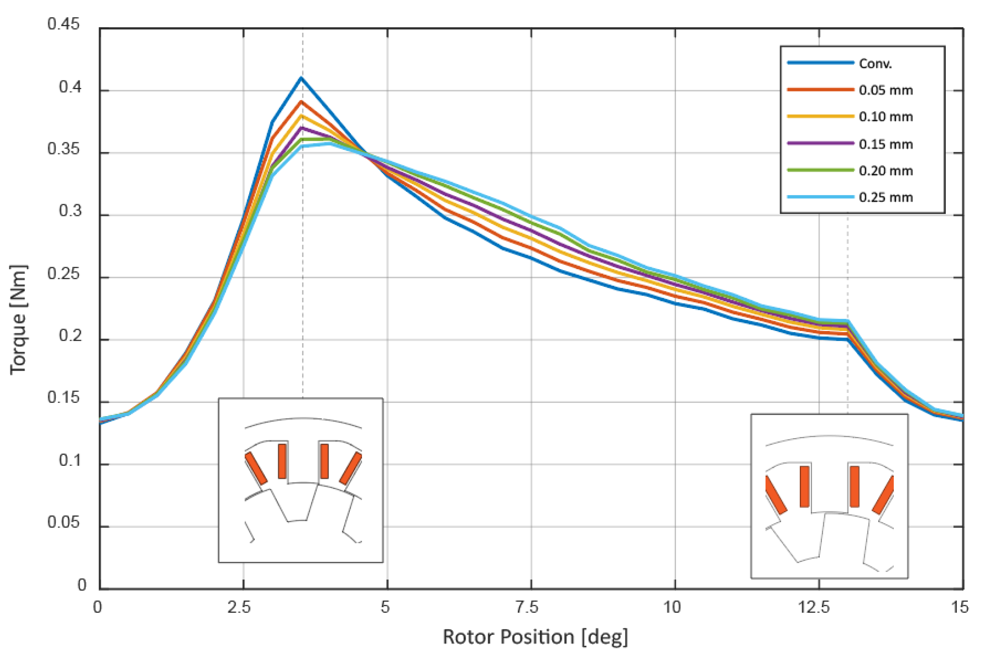
2.2. Non-Uniform Air-Gap
3. Proposed Rotor with Non-Uniform Air-Gap and One-Hole
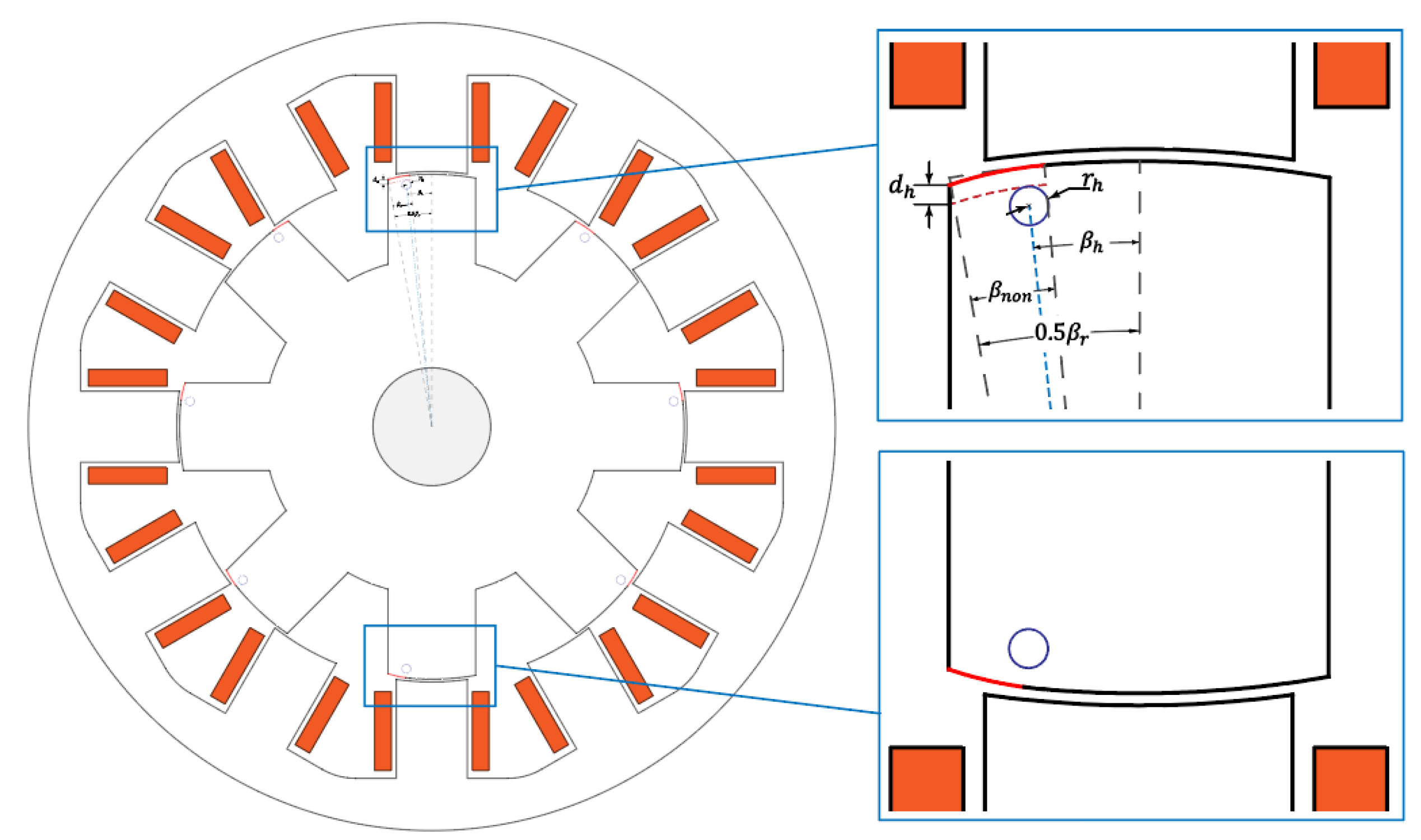
3.1. Design of Proposed Rotor
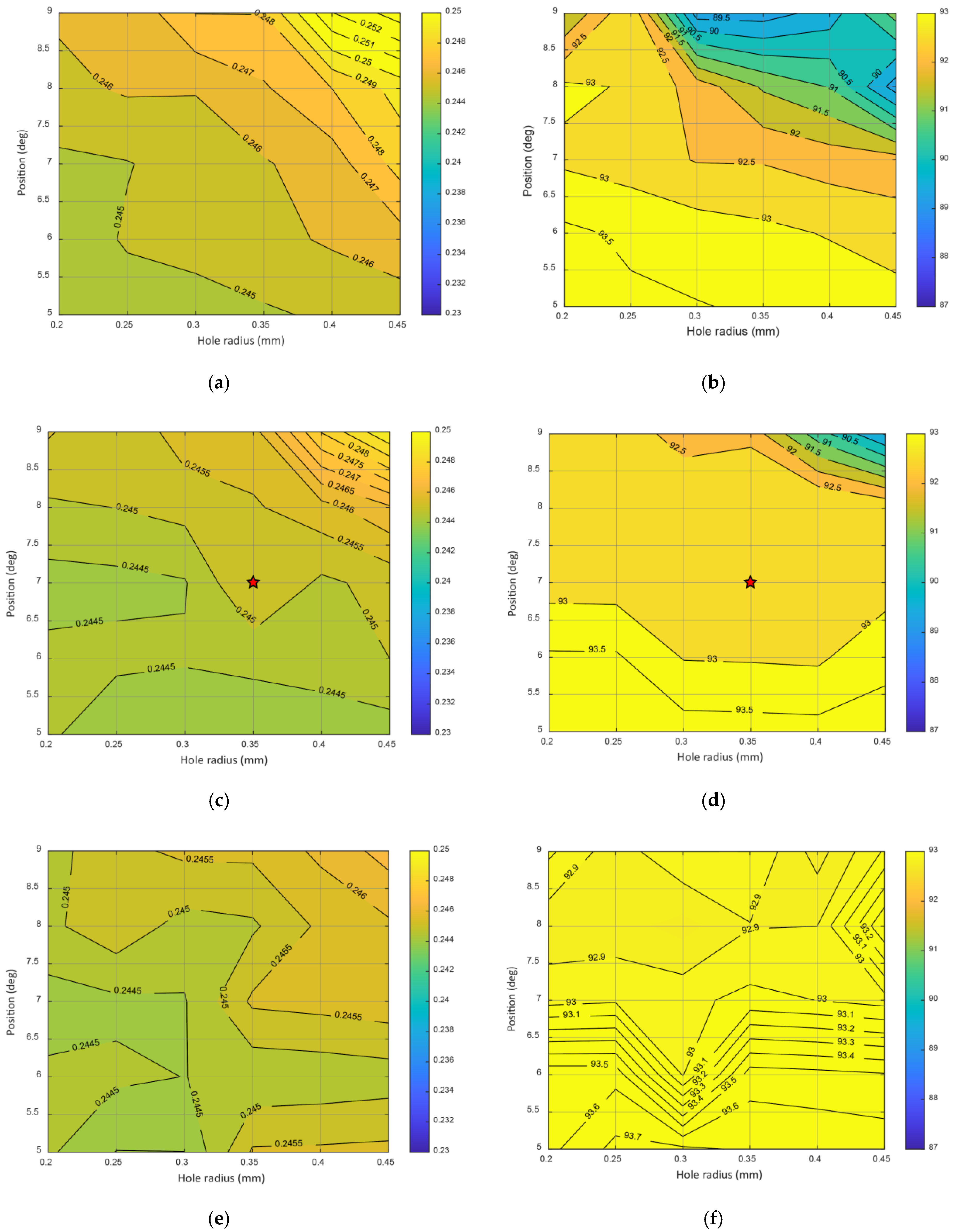
3.2. Simulation Results of Proposed Rotor
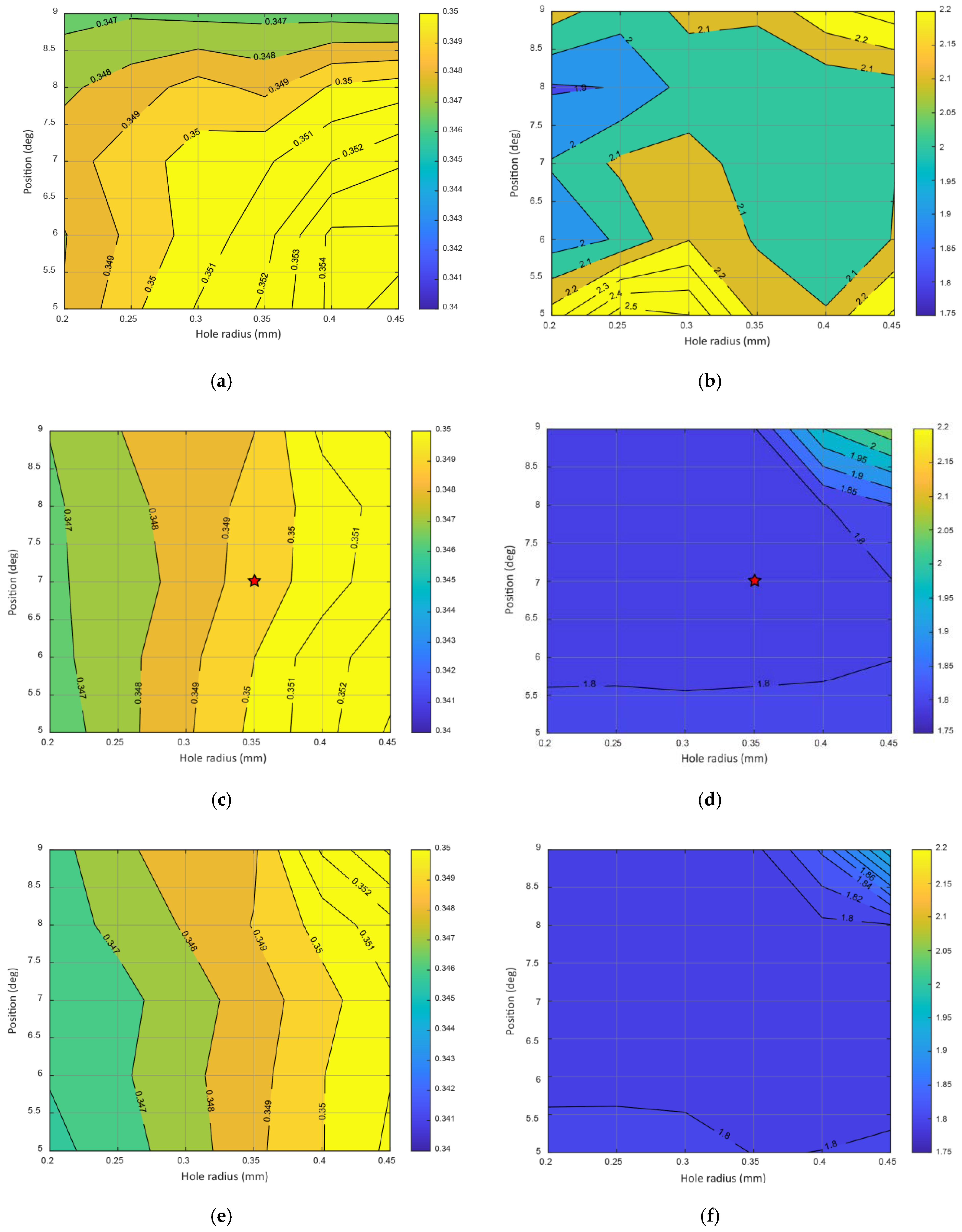
- When the hole is located too deep (large ) from the rotor-pole face, it has little effect. The change in the other two parameters at this point is unnoticeable.
- The same is applicable for . A greater value of produces a more noticeable change. However, this still depends on
- As for , the effect is more noticeable when it is closer to the side tip (larger ), this too depends on .
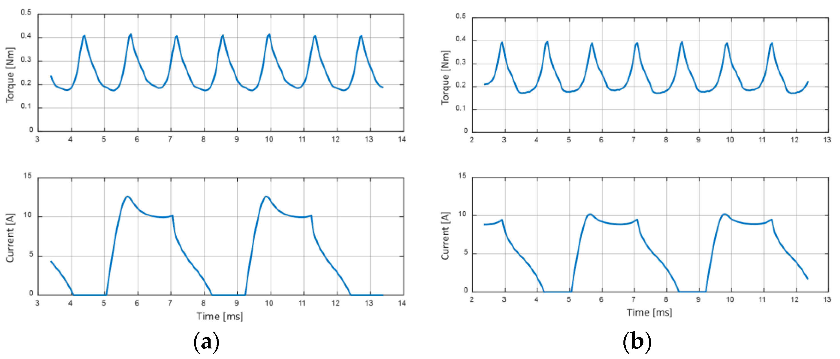
- It can be supposed that the hole does not affect the average torque by a wide range. The variance of maximum and minimum values from the three sets of figures is less than 3% of the rated torque of 0.24 Nm.
- Torque ripple, however, shows a slightly higher variance of 4.2%.
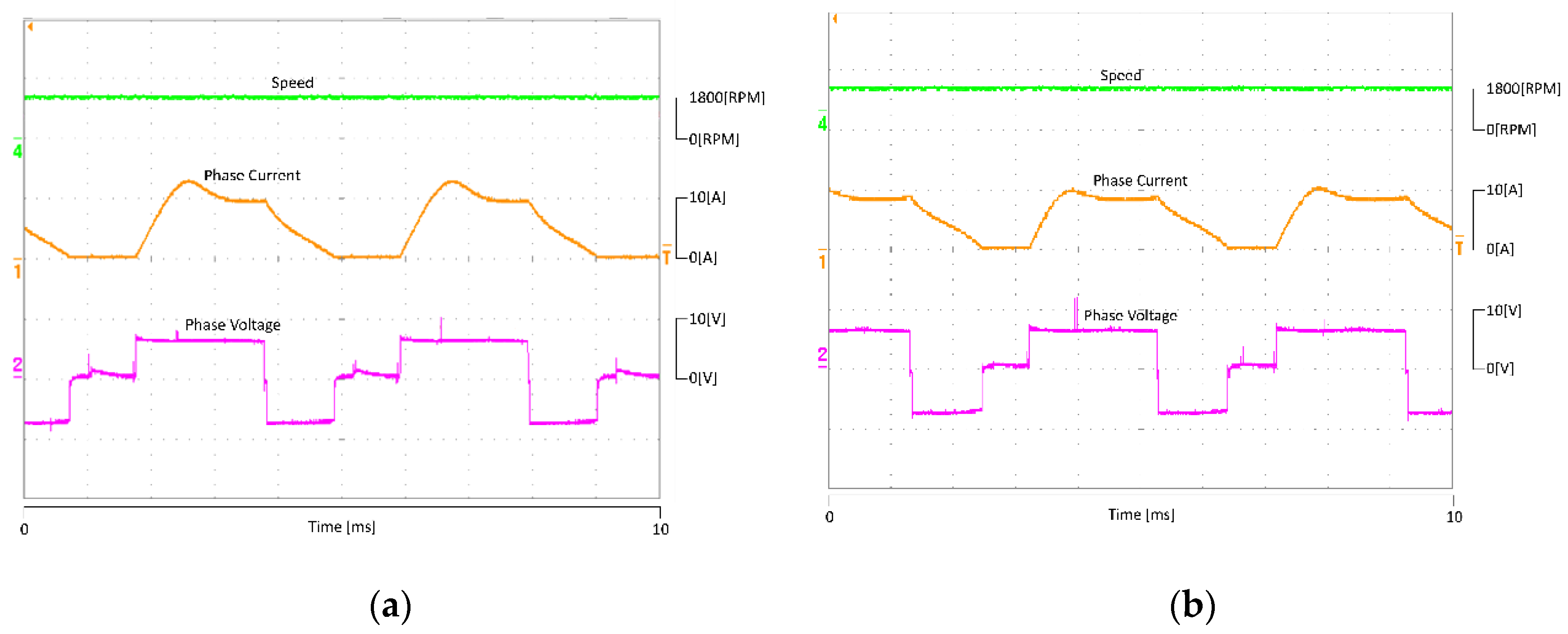
4. Experimental Results
5. Discussions
6. Conclusions
Author Contributions
Funding
Conflicts of Interest
References
- Li, C.; Wang, G.; Li, Y.; Xu, A. Robust Adaptive Neural Network Control for Switched Reluctance Motor Drives. Automatika 2018, 59, 24–34. [Google Scholar] [CrossRef]
- Zhu, Y.; Yang, C.; Yue, Y.; Wei, W.; Zhao, C. Design and Optimisation of an In-Wheel Switched Reluctance Motor for Electric Vehicles. IET Intell. Transp. Syst. 2018, 13, 175–182. [Google Scholar] [CrossRef]
- Elhomdy, E.; Li, G.; Liu, J.; Bukhari, S.A.; Cao, W.-P. Design and Experimental Verification of a 72/48 Switched Reluctance Motor for Low-Speed Direct-Drive Mining Applications. Energies 2018, 11, 192. [Google Scholar] [CrossRef] [Green Version]
- Boynov, K.; Paulides, J.J.H.; Lomonova, E.A. Comparative Analysis of the SRM as an Alternative to the PM Motor for Automotive Applications. COMPEL Int. J. Comput. Math. Electr. Electron. Eng. 2014, 33, 1599–1612. [Google Scholar] [CrossRef]
- Xu, A.-d.; Zhao, X.; He, K.; Cao, Y. Torque-Ripple Reduction of SRM Using Optimised Voltage Vector in DTC. IET Electr. Syst. Transp. 2018, 8, 35–43. [Google Scholar] [CrossRef]
- Gan, C.; Wu, J.; Sun, Q.; Kong, W.; Li, H.; Hu, Y. A Review on Machine Topologies and Control Techniques for Low-Noise Switched Reluctance Motors in Electric Vehicle Applications. IEEE Access 2018, 6, 31430–31443. [Google Scholar] [CrossRef]
- Abdel-Fadil, R.; Al-Amyal, F.; Számel, L. Torque Ripples Minimization Strategies of Switched Reluctance Motor—A Review. In Proceedings of the 2019 International IEEE Conference and Workshop in Óbuda on Electrical and Power Engineering (CANDO-EPE), Budapest, Hungary, 20–21 November 2019; pp. 41–46. [Google Scholar] [CrossRef]
- Shahabi, A.; Rashidi, A.; Nejad, S. Commutation Angles Adjustment in SRM Drives to Reduce Torque Ripple below the Motor Base Speed. Turk. J. Electr. Eng. Comput. Sci. 2016, 24, 669–682. [Google Scholar] [CrossRef]
- Lan, Y.; Benomar, Y.; Deepak, K.; Aksoz, A.; Baghdadi, M.E.; Bostanci, E.; Hegazy, O. Switched Reluctance Motors and Drive Systems for Electric Vehicle Powertrains: State of the Art Analysis and Future Trends. Energies 2021, 14, 2079. [Google Scholar] [CrossRef]
- Seshadri, A.; Lenin, N.C. Review Based on Losses, Torque Ripple, Vibration and Noise in Switched Reluctance Motor. IET Electr. Power Appl. 2020, 14, 1311–1326. [Google Scholar] [CrossRef]
- Ding, W.; Yin, Z.; Liu, L.; Lou, J.; Hu, Y.; Liu, Y. Magnetic Circuit Model and Finite-Element Analysis of a Modular Switched Reluctance Machine with E-Core Stators and Multi-Layer Common Rotors. IET Electr. Power Appl. 2014, 8, 296–309. [Google Scholar] [CrossRef]
- Lee, D.-H.; Ahn, J.-W. Performance of High-Speed 4/2 Switched Reluctance Motor. J. Electr. Eng. Technol. 2011, 6, 640–646. [Google Scholar] [CrossRef] [Green Version]
- Marcsa, D.; Kuczmann, M. Design and Control for Torque Ripple Reduction of a 3-Phase Switched Reluctance Motor. Comput. Math. Appl. 2017, 74, 89–95. [Google Scholar] [CrossRef]
- Lee, J.W.; Kim, H.S.; Kwon, B.I.; Kim, B.T. New Rotor Shape Design for Minimum Torque Ripple of SRM Using FEM. IEEE Trans. Magn. 2004, 40, 754–757. [Google Scholar] [CrossRef]
- Hur, J.; Kang, G.H.; Lee, J.Y.; Hong, J.P.; Lee, B.K. Design and Optimization of High Torque, Low Ripple Switched Reluctance Motor with Flux Barrier for Direct Drive. In Proceedings of the Conference Record of the 2004 IEEE Industry Applications Conference, 2004. 39th IAS Annual Meeting, Seattle, WA, USA, 3–7 October 2004; p. 407. [Google Scholar] [CrossRef]
- Sanada, M.; Morimoto, S.; Takeda, Y.; Matsui, N. Novel Rotor Pole Design of Switched Reluctance Motors to Reduce the Acoustic Noise. In Proceedings of the Conference Record of the 2000 IEEE Industry Applications Conference. Thirty-Fifth IAS Annual Meeting and World Conference on Industrial Applications of Electrical Energy (Cat. No.00CH37129), Rome, Italy, 8–12 October 2000; pp. 107–113. [Google Scholar] [CrossRef]
- Zhang, H.; Wang, S. Topology Optimization of Rotor Pole in Switched Reluctance Motor for Minimum Torque Ripple. Electr. Power Compon. Syst. 2017, 45, 905–911. [Google Scholar] [CrossRef]
- Moallem, M.; Ong, C.M.; Unnewehr, L.E. Effect of Rotor Profiles on the Torque of a Switched Reluctance Motor. In Proceedings of the Conference Record of the 1990 IEEE Industry Applications Society Annual Meeting, Seattle, WA, USA, 7–12 October 1990; pp. 247–253. [Google Scholar] [CrossRef]
- Nabeta, S.I.; Chabu, I.E.; Lebensztajn, L.; Correa, D.A.P.; da Silva, W.M.; Hameyer, K. Mitigation of the Torque Ripple of a Switched Reluctance Motor through a Multiobjective Optimization. IEEE Trans. Magn. 2008, 44, 1018–1021. [Google Scholar] [CrossRef]
- Hieu, P.T.; Lee, D.-H.; Ahn, J.-W. High Speed Segmental Stator Type 4/3 SRM: Design, Analysis, and Experimental Verification. J. Electr. Eng. Technol. 2017, 12, 1864–1871. [Google Scholar] [CrossRef]
- Choi, Y.K.; Yoon, H.S.; Koh, C.S. Pole-Shape Optimization of a Switched-Reluctance Motor for Torque Ripple Reduction. IEEE Trans. Magn. 2007, 43, 1797–1800. [Google Scholar] [CrossRef]
- Lukman, G.F.; Nguyen, X.S.; Ahn, J.-W. Design of a Low Torque Ripple Three-Phase SRM for Automotive Shift-by-Wire Actuator. Energies 2020, 13, 2329. [Google Scholar] [CrossRef]


| Parameters | Value |
|---|---|
| Stator outer diameter [mm] | 72 |
| Stack length [mm] | 18 |
| DC-link voltage [V] | 12 |
| Output speed [RPM] | 1800 |
| Output torque [Nm] | 0.24 |
| Maximum current [A] | 30 |
| Parameters | Conventional | Value of Non-Uniform Models | ||||
|---|---|---|---|---|---|---|
| 0.05 | 0.10 | 0.15 | 0.20 | 0.25 | ||
| Average torque | 1.00 | 1.00 | 1.02 | 1.02 | 1.03 | 1.03 |
| Torque ripple | 1.00 | 0.92 | 0.87 | 0.83 | 0.79 | 0.77 |
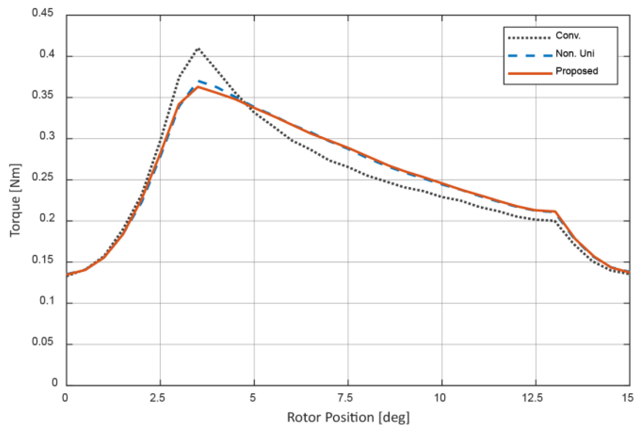
| Parameters | Conventional | Non-Uniform | Proposed |
|---|---|---|---|
| Average torque [Nm] | 0.24 | 0.25 | 0.25 |
| Torque ripple [%] | 114.39 | 95.04 | 92.97 |
Publisher’s Note: MDPI stays neutral with regard to jurisdictional claims in published maps and institutional affiliations. |
© 2021 by the authors. Licensee MDPI, Basel, Switzerland. This article is an open access article distributed under the terms and conditions of the Creative Commons Attribution (CC BY) license (https://creativecommons.org/licenses/by/4.0/).
Share and Cite
Lukman, G.F.; Ahn, J.-W. Torque Ripple Reduction of Switched Reluctance Motor with Non-Uniform Air-Gap and a Rotor Hole. Machines 2021, 9, 348. https://doi.org/10.3390/machines9120348
Lukman GF, Ahn J-W. Torque Ripple Reduction of Switched Reluctance Motor with Non-Uniform Air-Gap and a Rotor Hole. Machines. 2021; 9(12):348. https://doi.org/10.3390/machines9120348
Chicago/Turabian StyleLukman, Grace Firsta, and Jin-Woo Ahn. 2021. "Torque Ripple Reduction of Switched Reluctance Motor with Non-Uniform Air-Gap and a Rotor Hole" Machines 9, no. 12: 348. https://doi.org/10.3390/machines9120348