Article

Performance of Relative Clearance Ratio of Floating Ring Bearing for Turbocharger-Rotor System Stability

1
Department of Mechanical Engineering, Hebei University of Technology, Tianjin 300130, China
2
Department of Mechanical Engineering, Hebei University of Science and Technology, Shijiazhuang 050018, China
*
Author to whom correspondence should be addressed.
Machines 2021, 9(11), 285; https://doi.org/10.3390/machines9110285
Submission received: 10 September 2021 / Revised: 7 November 2021 / Accepted: 8 November 2021 / Published: 12 November 2021
(This article belongs to the Section Turbomachinery)

Abstract

:
The floating ring bearing (FRB) has been widely used in the field of high-speed rotating machinery such as turbochargers, aviation engines and so on, because of its simple structure, high efficiency and low power consumption. In order to obtain the best ratio between inter-oil clearance and shaft radius of the floating ring bearing necessitates the design reference of dimensional parameters for the design of floating ring bearings. This study, based on the transfer-matrix method, developed the dynamic model of the floating ring bearing-rotor system, and, using the Runge–Kutta analysis method for floating ring bearings, the influence of oil film relative clearance ratio of floating rings on rotor system stability was analyzed and studied. The optimum clearance ratio between inner oil film and the shaft of floating ring bearings is λ = 0.01. This research can provide some theoretical support for the design of parameters and fault diagnosis of rotor floating ring bearing systems.

1. Introduction

A floating ring bearing is a kind of double oil-film bearing, which has the advantages of simple structure and high efficiency. The floating ring is between the journal and the rotating shaft. It can make the bearing have the characteristic of double oil-film support, which is conducive to improving the stability of the system. A lot of research work has been done about principle and theoretical analysis of floating ring bearings by domestic and foreign scholars. For example, the influence of floating ring inner and outer oil-film clearance ratio on turbocharger-rotor system instability was studied [1]. The study shows that: when the gap ratio is small, inner oil-film whirl will lead to a destabilizing interval of the rotor system, and an unstable interval of the rotor system depending on outside oil-film whirl while gap ratio is larger. Using the Alford model, the impact of seal fluid excitation force and tip clearance excitation force on rotor dynamic characteristics is taken to be calculated about one type of ball bearing for automotive turbochargers, and the results show that seal fluid excitation force increases system damping and reduces the amplitude of the ball turbocharger rotor bearing system, system excitation increases the cross stiffness, and reduces the steady-state response amplitude [2,3]. The finite-element model of the turbocharger rotor is presented, and the model is investigated considering the gyroscopic moment of the inertia wheel, bearing, sleeve and other factors, the change trend in different bearing stiffness on the critical speed and mode of the turbocharger rotor is calculated and the influence of support stiffness on the dynamic characteristic of the turbocharger rotor is analyzed. The working speed of the turbocharger rotor is high, up to 300,000 rpm. It has strict technical requirements and is a research hotspot. Zhu et al. [4] present a dynamic model of the double cantilever of a turbocharger rotor and carry out numerical analysis using MATLAB software. Through spectrum analysis, they show that the frequency of oil whirl is slightly less than 0.5 times the working speed; in small eccentricity, oil-film instability of the rotor system will occur with small rotating speed, and with rotor eccentricity increasing the stability of rotor movement will be improved. The inner oil-film clearance in the floating ring bearing directly contacts the rotor, which has a great influence on the vibration of the rotor. All of the abovementioned studies do not take into account the influence of the relative clearance of the floating ring bearing on the dynamic stability of the rotor system. The rotor system of the turbocharger is complex and has nonlinear dynamic characteristics, so its analysis and calculation are cumbersome.
This work aims to evaluate dimension parameters of FRB in the stability analysis of rotating systems supported by FRB. For the dynamic problems of floating ring bearings, researchers have proposed several simplified linear methods to analyze the dynamic characteristics of bearings [5]. The multi-scale finite-element method is used to establish the dynamic model of floating ring bearings, in which paper, the calculation results are compared with the test results to verify its correctness. This method improves the efficiency of calculation and analysis [6]. For the high-speed rotor of a turbocharger, its working speed is high, so the lubrication of the rotor system is very important. For the bearing lubrication problem, the floating ring calculation model is presented, based on the numerical solution of Reynolds equation and Pavel, and the calculation results are analyzed [7,8]. A nonlinear model considering the influence of thermal fluid is carried out, and the influence of thermal fluid dynamic model on rotor dynamic stability is proposed [9]. The finite-element method is used to establish the calculation model of the floating ring rotor, to simulate the system startup and shutdown process, and calculate the oil-film force in each stage of the system [10]. Using the multi-scale calculation method and considering the influence of various coupling factors, a new bearing-modified lubrication calculation model is proposed to improve the efficiency of bearing system analysis [11]. In the past two decades, it is generally believed that bearing surface roughness has a great impact on bearing performance. Therefore, many researchers focus on the study of surface texture as micro trap [12,13,14,15,16]. Bearing failure is closely related to its surface morphology [17,18,19]. The influence of the bifurcation sequence on the bearing system is studied by using a nonlinear hydro-dynamic model, and analyzed by calculating the working state of the bearing rotor [20,21,22,23,24]. With the continuous development of dynamic theory and technology, the accuracy of its calculation method and modeling is continuously improved, which provides support for the dynamic analysis of the rotor system [25].
With the popularization of the application technology of rotating machinery, research of its nonlinear dynamics has become one of the hotspots [26,27,28]. The factors considered in calculation are increasing, including shaft torsional deformation and complex structural factors. Non-contact bearings, such as magnetic bearings and air bearings [29,30], are also another hot issue studied in recent years. However, the application of this kind of advanced bearing is not common at present. For the turbocharger with the function of energy saving and emission reduction, the floating ring bearing is widely used, and its size parameters have a great impact on the performance of the rotor system, especially its mating size, and the relative clearance of the inner oil film is closely related to the working stability of the system. The above research results do not consider the influence of the ratio of oil-film clearance to shaft radius on the stability of bearing system.
This research takes a floating ring bearing-rotor system as the research object, using the Prohl transfer-matrix method to develop the dynamics model of the floating ring bearing-rotor system, and, using the Runge–Kutta method, the concept of relative clearance of floating ring bearing is proposed, and the effect of floating ring bearing relative clearance on the stability of a rotor system is analyzed, which provides an important reference for the design and application of floating ring bearings. The results show that with an increase in the relative clearance, the rotor stable-speed range of single periodic will decrease, and the instability initial speed will decrease. At the end of the work, the floating ring rotor test-bed is established to test the vibration characteristics under different parameters to verify the correctness of the theoretical model and conclusion of this study.

2. Dynamic Model of Floating Ring Bearing-Rotor System

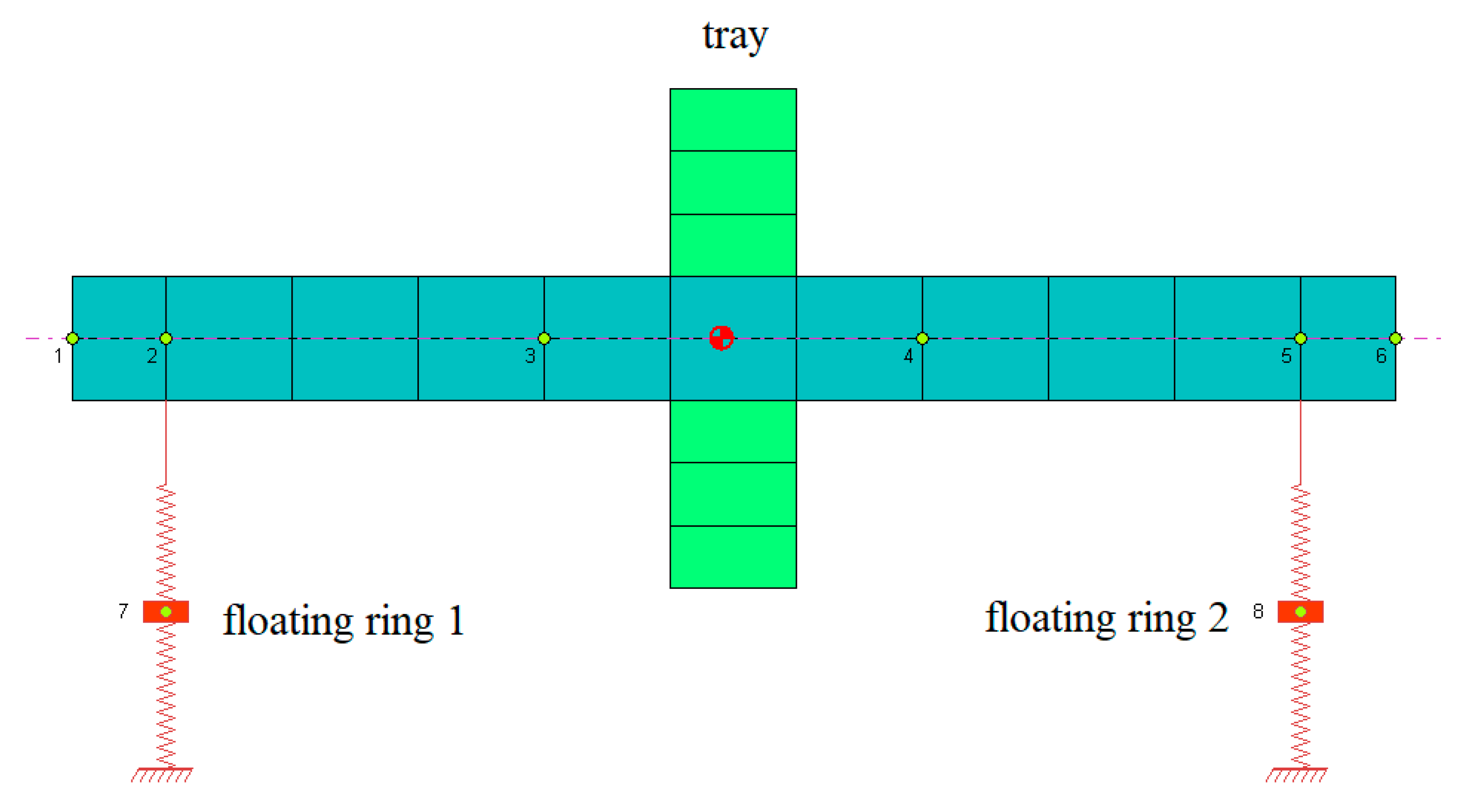
2.1. Rotor Dynamics Model of Floating Ring Bearing

The rotor system can be simplified to a three-mass and two-disc massless shaft section. When floating ring bearing-rotor dynamics system modeling, support for the rotor left and right ends are floating ring bearings, intermediate is a rigid single disc. The dynamics finite-element model is shown in Figure 1. At the same time, the gyroscopic effect is neglected, and the torsion and shear effects are not considered.
When analyzing the floating ring, the quality of the floating ring is very light, as the floating ring is seen as no mass eccentricity, ignoring the influence of the centrifugal force produced by the floating ring. The floating ring is only affected by the gravity of the floating ring, i.e., the inner and outer oil-film force. The rotor is subjected to force, and the journal is affected by the rotor gravity, the oil-film force and the centrifugal. According to Newton’s second law, the dynamic equation of the floating ring bearing-rotor system is:
{ m r x ¨ r = f o x f i x m r y ¨ r = f o y f i y m r g m j x ¨ j = f i x + m j e ω j sin ( ω j t ) m j y ¨ j = f i y + m j e ω j cos ( ω j t ) m j g
where m r g is floating ring weight; m j g is rotor weight. The inner and outer oil-film forces need to be treated with the rotor system equation without quantization, where τ = ω j t is dimensionless time, dimensionless displacement and velocity of the ring is: X r = x r / c i , Y r = y r / c i , X r = x ˙ r / c i ω j Y r = y ˙ r / c i ω j , dimensionless displacement and velocity of the rotor is: X j = x ¯ j / c i , Y j = y ¯ j / c i , X j = x ¯ ˙ j / ( c i ω j ) , Y j = y ¯ ˙ j / ( c i ω j ) . The dimensionless dynamic equations of the floating ring and the rotor are obtained by the unified dimensionless treatment:
{ X r = F o x / M r F i x / M k Y r = F o y / M r F i y / M k G i X j = F i x / M j + ρ sin ( τ ) X r Y j = F i y / M j + ρ cos ( τ ) G i Y r

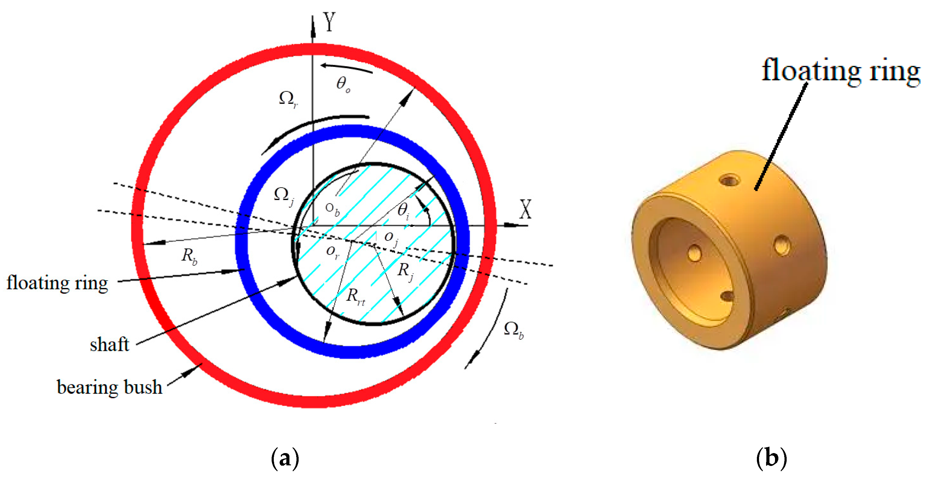
2.2. Inner and Outer Oil-Film Force Model of FRB

In this study, the length to diameter ratio of the floating ring bearing is 0.5 < L/D < 1, the eccentricity is less than 0.5 and the Capone short bearing oil-film force model is selected according to [31]. The dynamic model of the floating ring bearing is presented as shown in Figure 2. The ring is between the shaft and the bearing bush. An inner oil film is formed between the shaft and the floating ring, and an outer oil film is formed between the ring and bearing bush.
According to the theory of Capone modified short bearing, the dimensionless analytical formula of the outer oil-film force of the floating ring bearing along the direction of x and y [30] is:
{ F o x F o y } = A o { 3 X r V o G o sin α o 2 S o cos α o 3 Y r V o G o cos α o 2 S o sin α o }
The starting angle of the outer oil-film pressure of the floating ring bearing is α o :
α o = arctan Y r + 2 X r X r 2 Y r π 2 s i g n ( Y r + 2 X r X r 2 Y r ) π 2 s i g n ( Y r + 2 X r )
The symbols of A o , G o , V o , S o in the Equation (3) are as follows:
{ A o = [ ( X r 2 Y r ) 2 + ( Y r + 2 X r ) 2 ] 1 2 1 X r 2 Y r 2 G o ( X o , Y o , α o ) = 2 ( 1 X r 2 Y r 2 ) 1 2 [ π 2 + arctan Y r cos α o X r sin α o ( 1 X r 2 Y r 2 ) 1 2 ] V o ( X r , Y r , α o ) = 2 + ( Y r cos α o X r sin α o ) G o ( X r , Y r , α o ) 1 X r 2 Y r 2 S o ( X r , Y r , α o ) = X r cos α o + Y r sin α o 1 ( X r cos α o + Y r sin α o ) 2
According to the theory of Capone modified short bearing, the dimensionless analytical formula of the inner oil-film force of the floating ring bearing along the direction of x and y is:
{ F i x F i y } = A i { 3 X j V i G i sin α i 2 S i cos α i 3 Y j V i G i cos α i 2 S i sin α i }
the starting angle of the inner oil-film pressure of the floating ring bearing is α i :
α i = arctan Y ¯ j + 2 X ¯ j X ¯ j 2 Y ¯ j π 2 s i g n ( Y ¯ j + 2 X ¯ j X ¯ j 2 Y ¯ j ) π 2 s i g n ( Y ¯ j + 2 X ¯ j )
The expression of A i , G i , V i , S i is as follows:
{ A i = [ ( X ¯ r 2 Y ¯ r ) 2 + ( Y ¯ r + 2 X ¯ r ) 2 ] 1 2 1 X ¯ r 2 Y ¯ r 2 G i ( X ¯ j , Y ¯ j , α j ) = 2 ( 1 X ¯ r 2 Y ¯ r 2 ) 1 2 [ π 2 + arctan Y ¯ r cos α o X ¯ r sin α o ( 1 X ¯ r 2 Y ¯ r 2 ) 1 2 ] V i ( X ¯ j , Y ¯ j , α o ) = 2 + ( Y ¯ r cos α o X ¯ r sin α o ) G o ( X ¯ r , Y ¯ r , α o ) 1 X ¯ r 2 Y ¯ r 2 S i ( X ¯ j , Y ¯ j , α o ) = X ¯ r cos α o + Y ¯ r sin α o 1 ( X ¯ r cos α o + Y ¯ r sin α o ) 2
The correctness of Capone short bearing oil film in reference [30] has been verified in the response references. Therefore, the real internal and external oil-film force expression is:
f x i = σ F x i , f y j = σ F y j
where σ = μ ω R L ( R c ) 2 ( L 2 R ) 2 , μ is oil-film viscosity, R is the radius of the floating ring bearing and L is length of the floating ring bearing. Temperature has a great influence on the viscosity of lubricating oil. Therefore, the viscosity-temperature characteristics of lubricating oil should be considered in the calculation process. The rules between them are [9]:
μ = μ 0 e β ( T T 0 )
where μ 0 is the standard viscosity (T0), and β is the constant coefficient, T0 = 25 °C.
The internal oil-film force of the floating ring bearing is the integral result of the oil-film pressure at each point in the oil-film bearing area. The oil-film force of inner oil film in the floating ring bearing can be decomposed into two components in the x and y direction, and its integral expressions are:
F x i = 0 2 π 0 L p ( ϕ , z ) r cos ( ϕ + α ) d z d ϕ
F y i = 0 2 π 0 L p ( ϕ , z ) r sin ( ϕ + α ) d z d ϕ
where p is the oil-film pressure at a certain point, L is the bearing width and r is the inner radius of the floating ring. The expression of the oil-film force in the bearing can be obtained by numerical integration.
During the operation of the rotor system, the floating ring rotates with the journal. The speed of the floating ring is related to its structural parameters, lubricating oil viscosity and journal angular velocity. The ratio of the angular velocity of the floating ring to the shaft can be expressed as:
ω ¯ = ω R ω J = 1 1 + μ o μ i ( R o R i ) 3 L o L i c i c o
where, ω R , ω J are the angular velocities of the floating ring and journal, respectively, L i , L o are the internal and external diameter width of the floating ring and C i , C o are the internal and external clearance of the floating ring bearing, respectively.

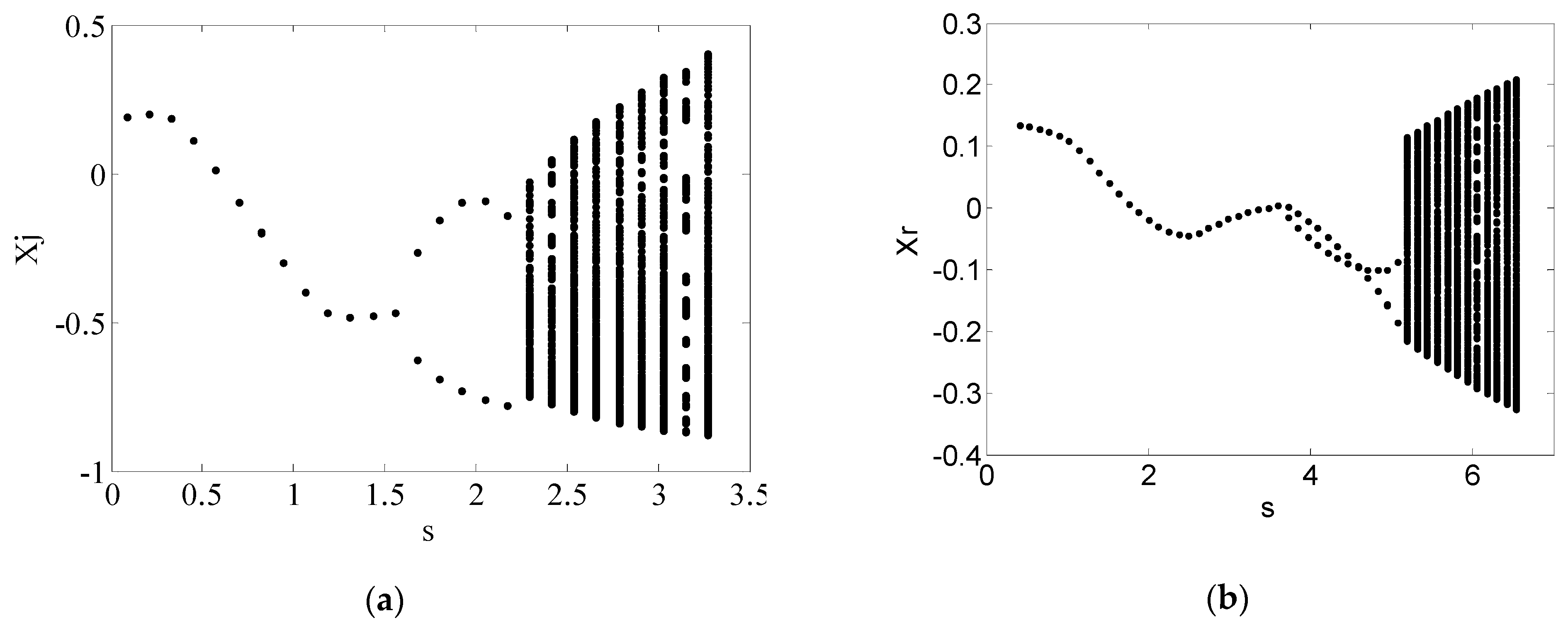
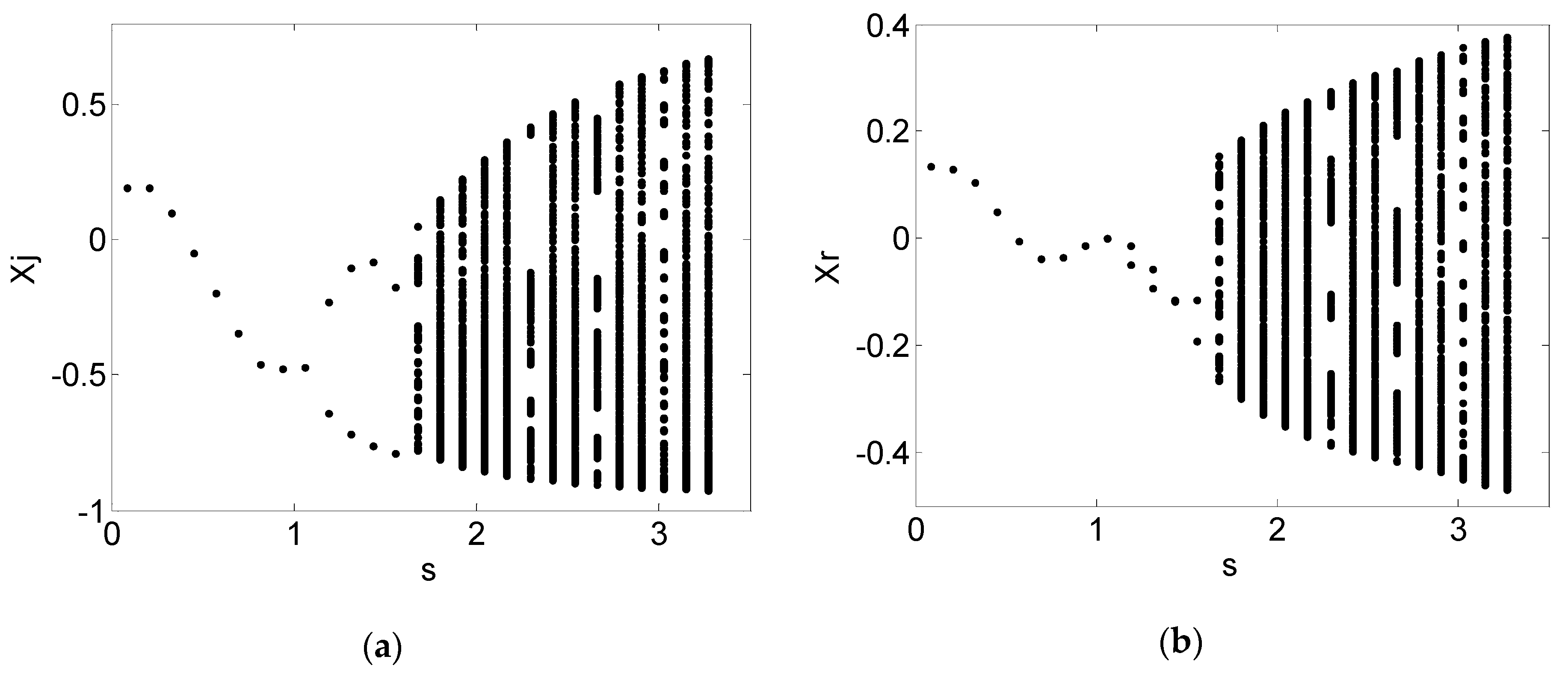
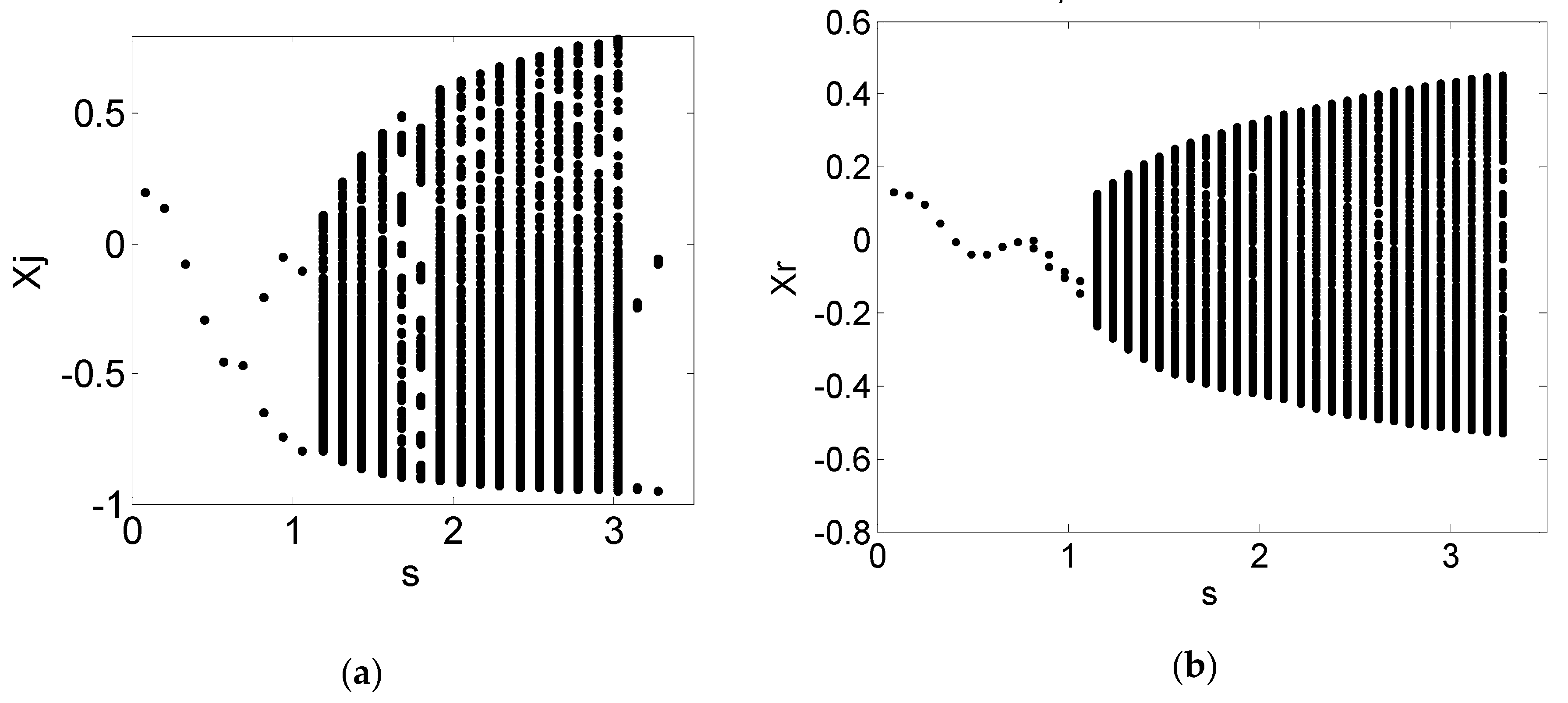
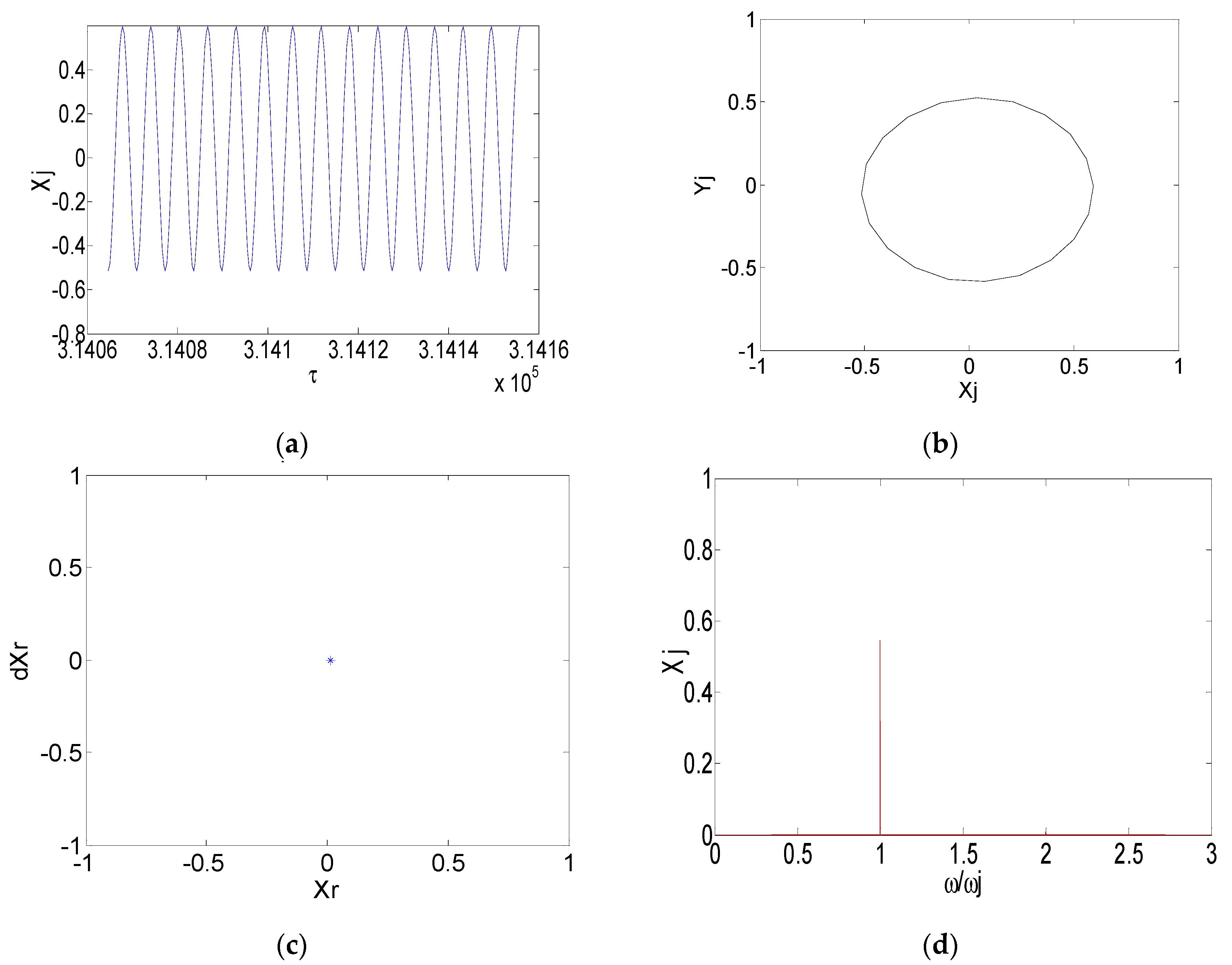
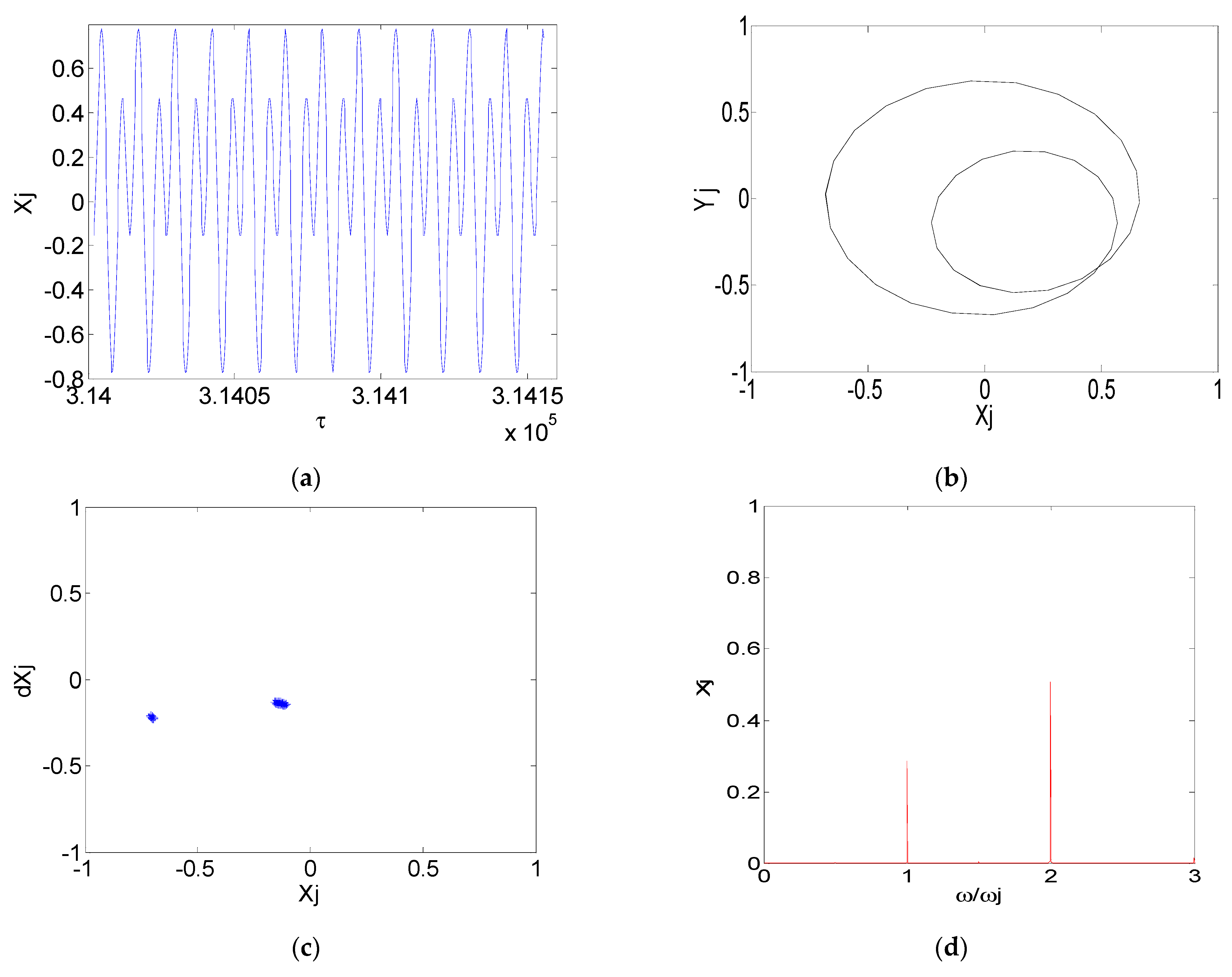
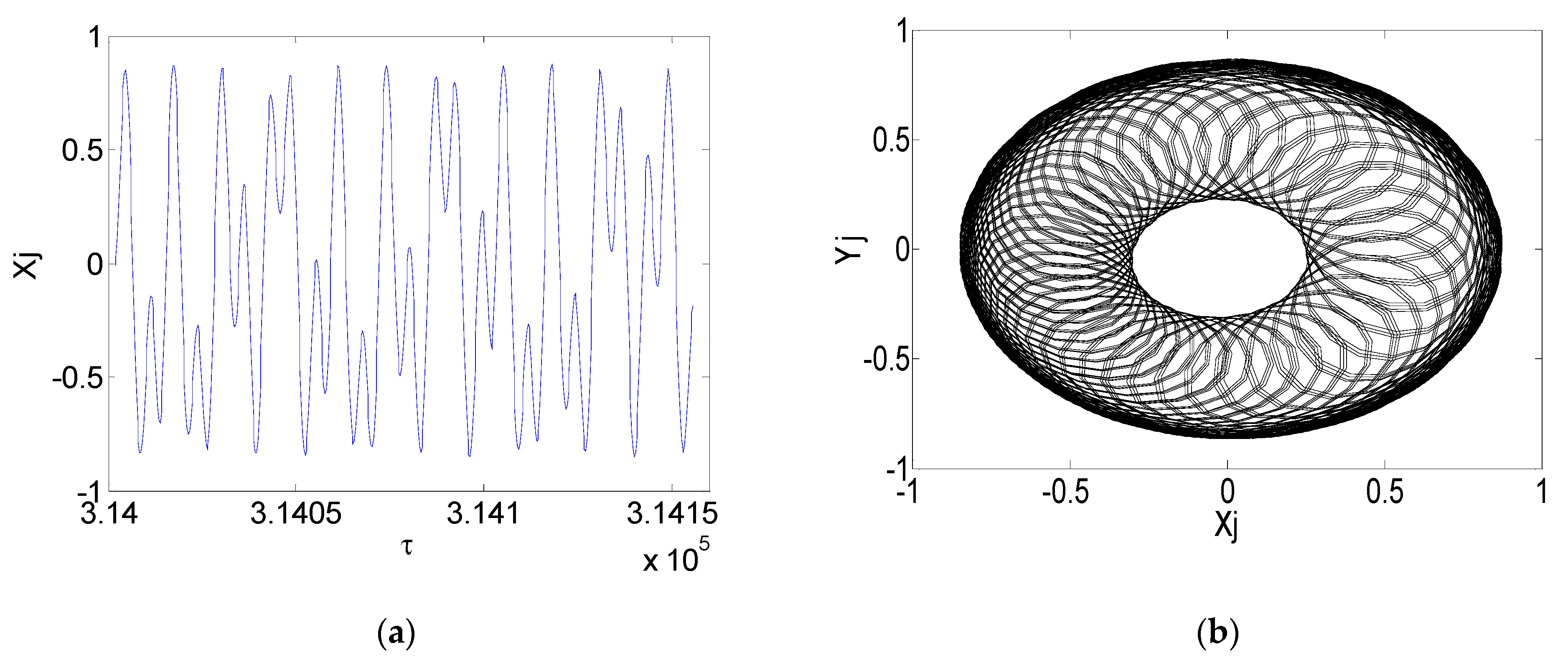
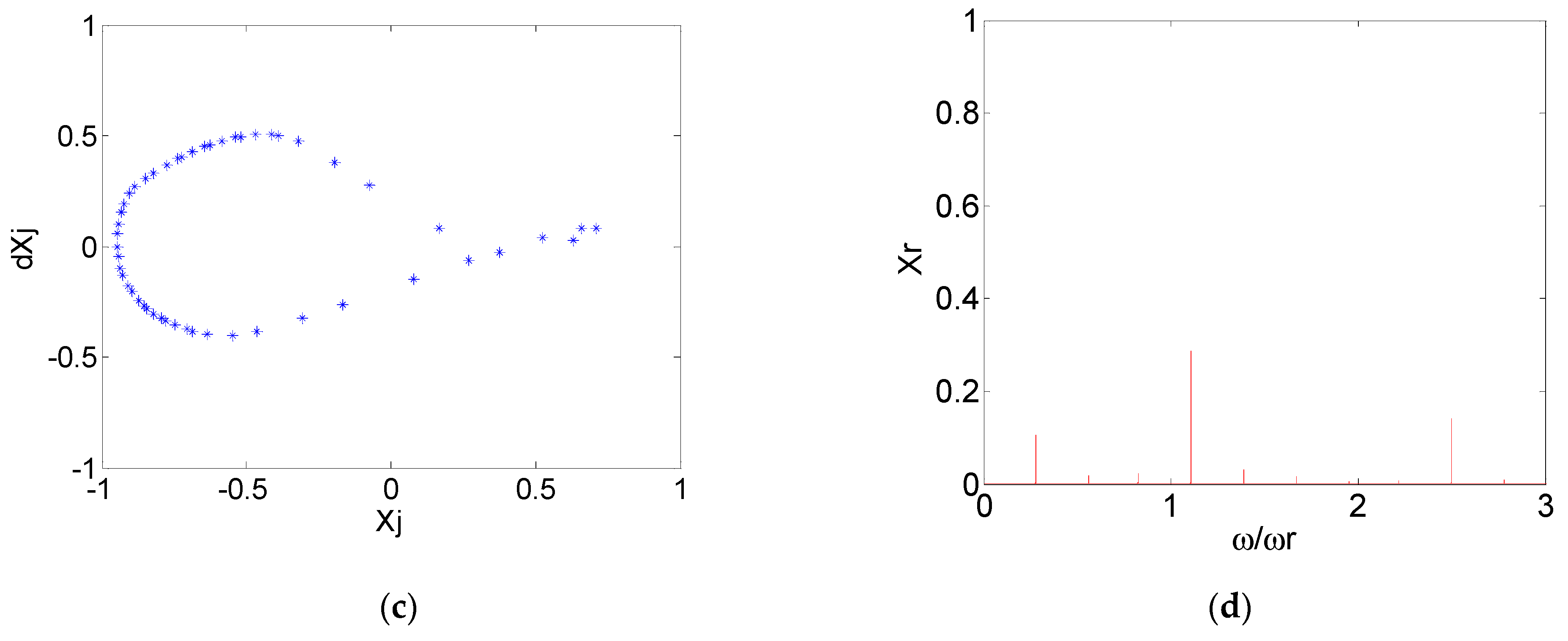
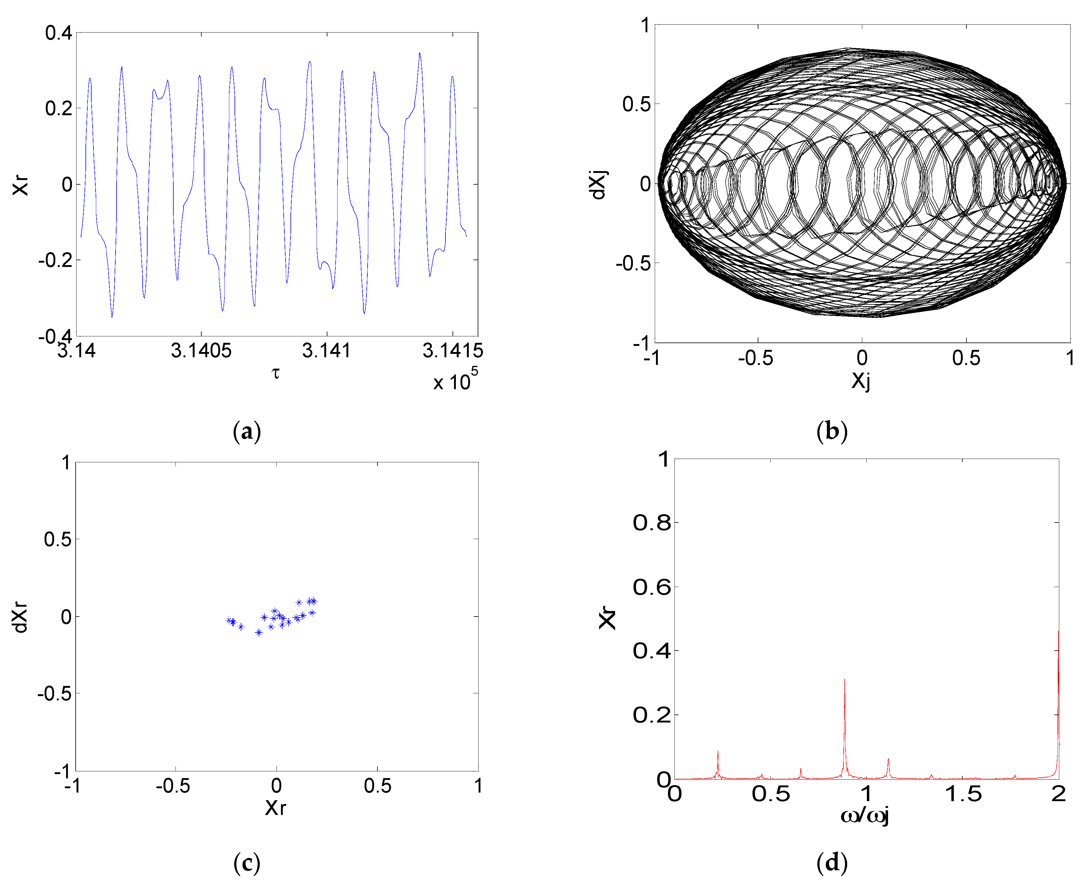
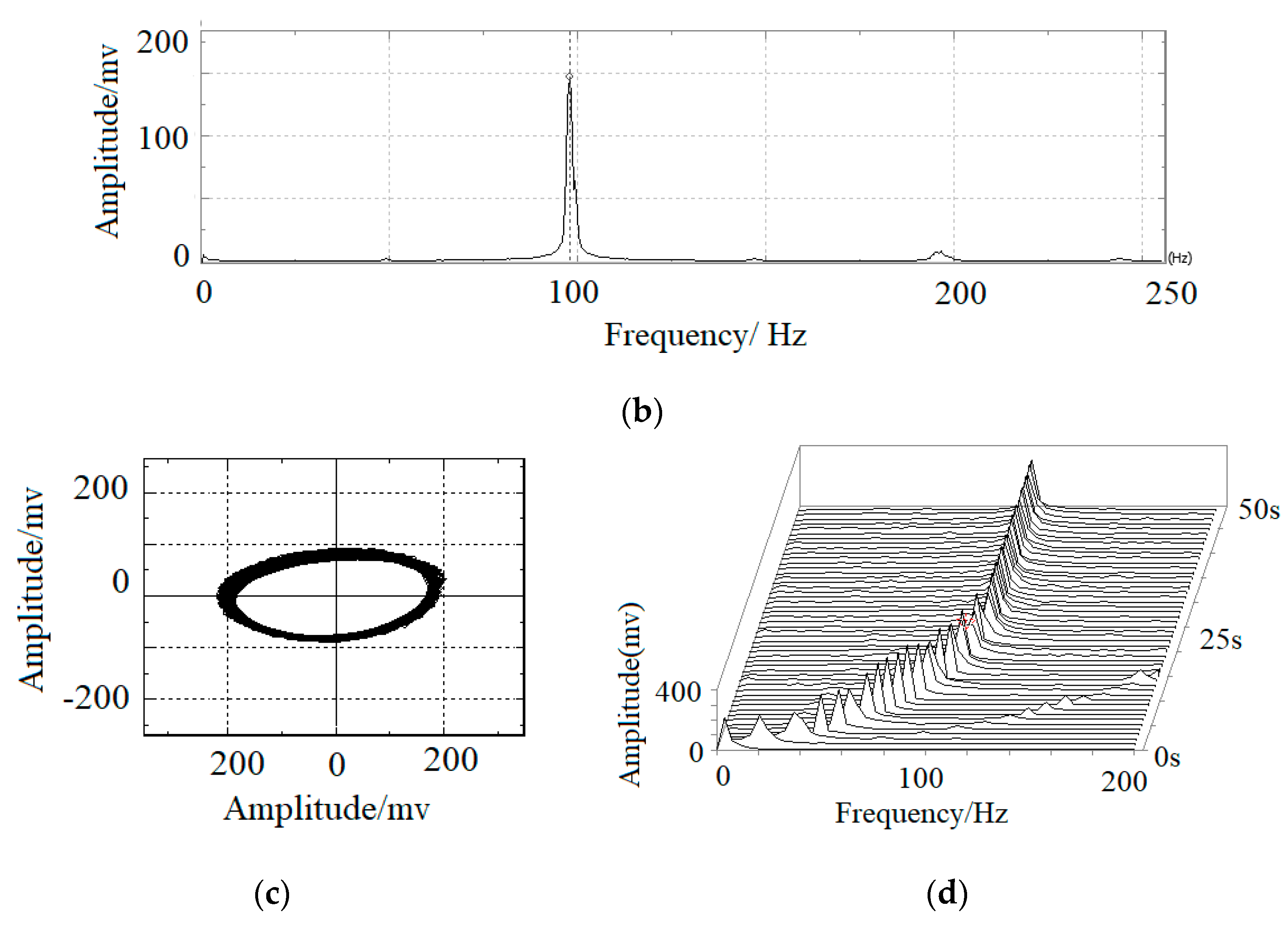
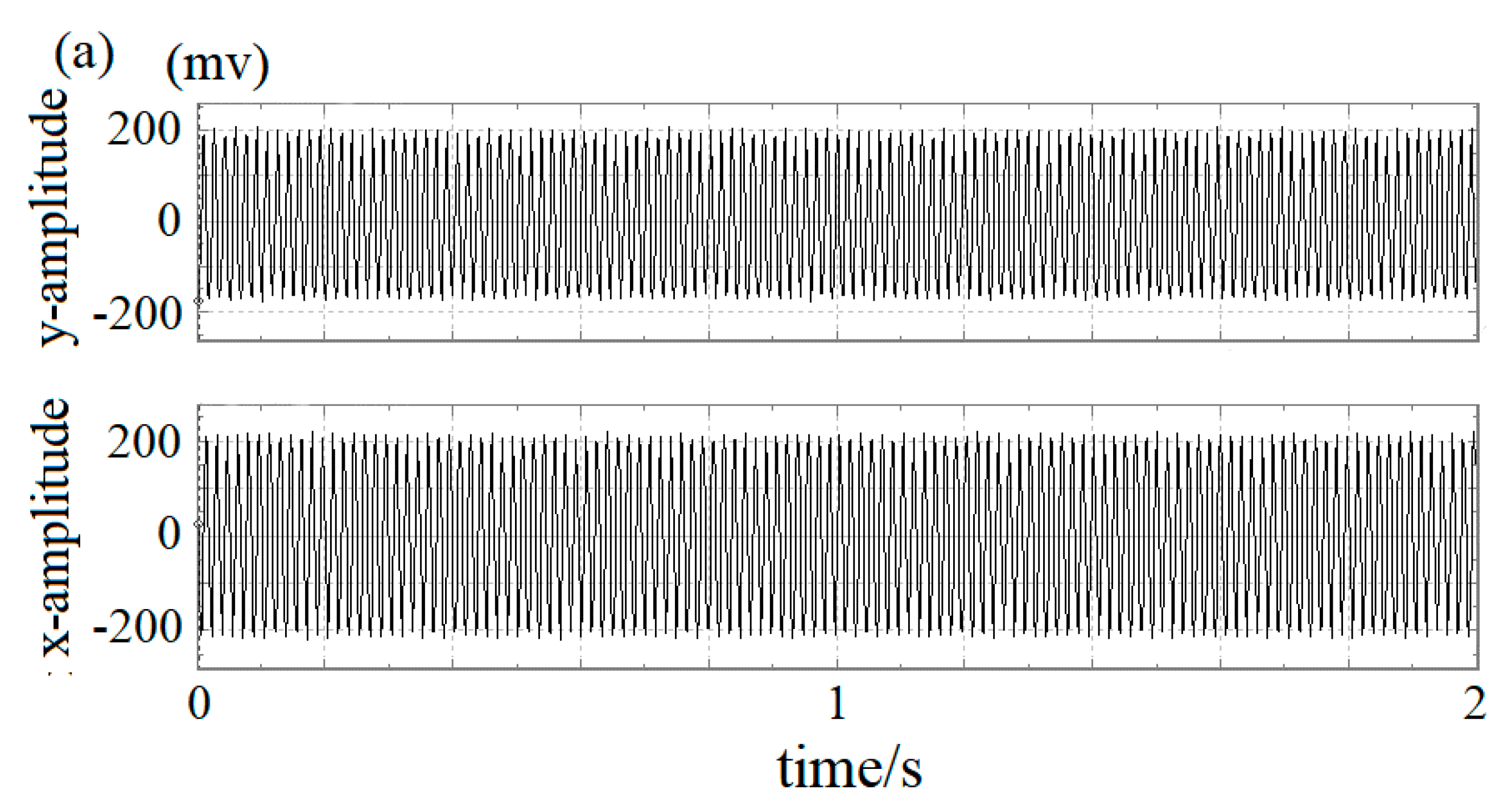
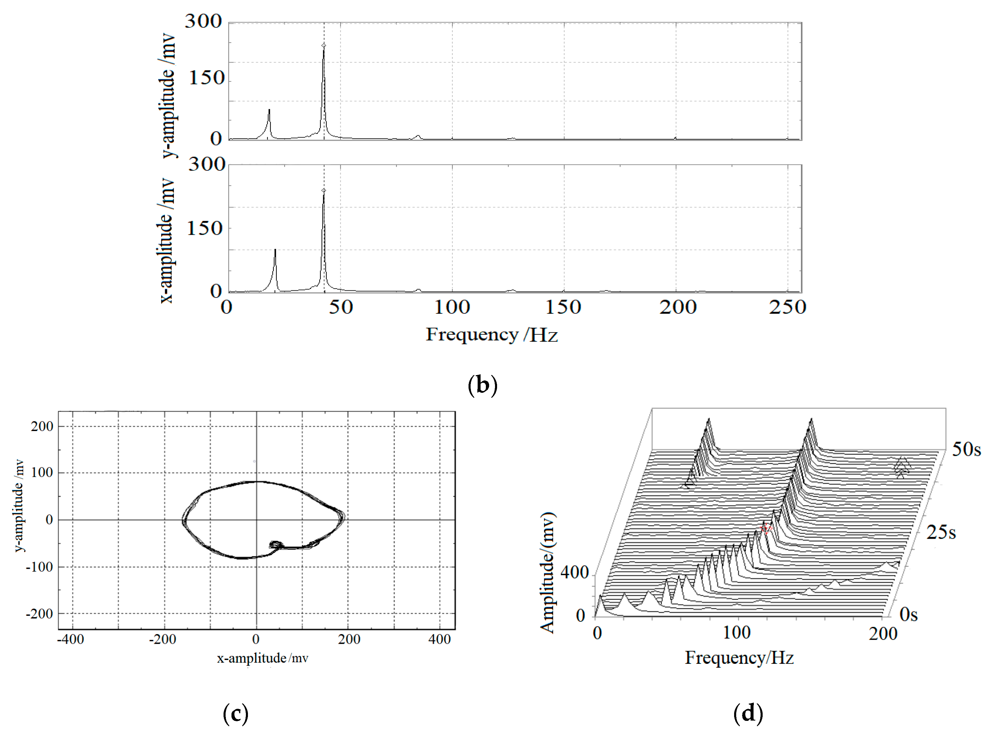
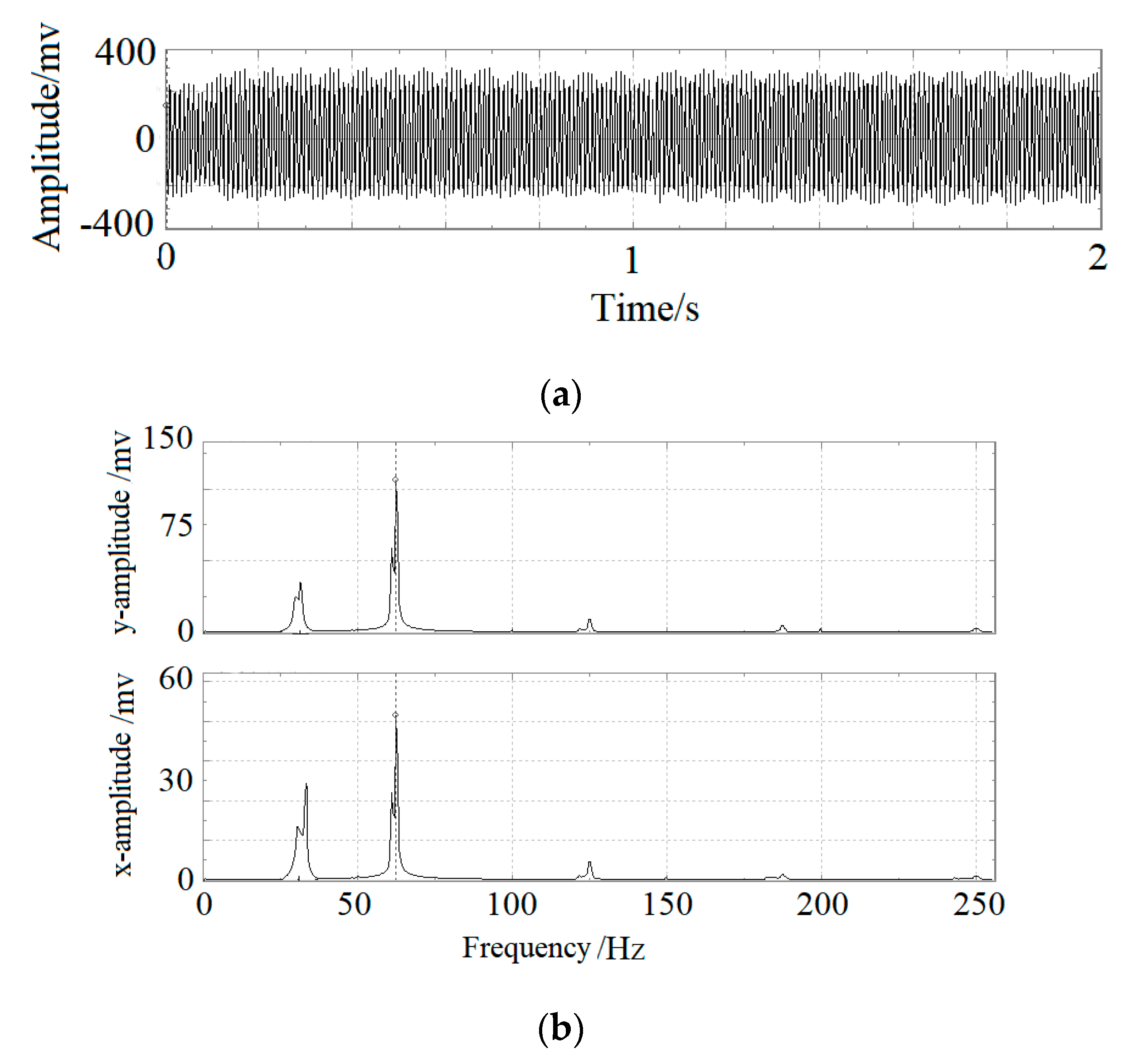
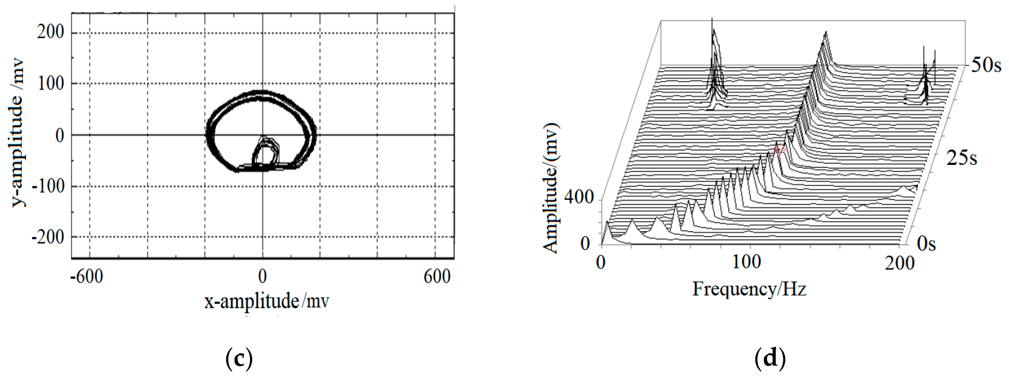
3. Numerical Simulation and Result Analysis

In this study, we took a floating ring bearing-rotor system as an example. Based on the mathematical model of the above Formulas (1), (2), (6) and (9), the parameters were taken into dimensionless equations, using the standard four-order Runge–Kutta method to perform numerical calculation. The structure parameters of the floating ring bearing-rotor system and floating ring used in this study are shown in Table 1 and Table 2, which are derived from references [4,5].
The relative clearance value is the ratio of the oil-film clearance value and the shaft radius in the floating ring bearing. The radius of the shaft neck was r = 3.5 mm, and s was defined as the ratio of the rotor speed and the first critical speed, according to Ref. [1]. When ratio of the inside clearance and outside clearance of the oil film is, it can guarantee the rotor system operation in normal working range [22,32,33,34]. Therefore, the floating ring bearing oil-film clearance ratio is selected as fixed value, changing inner oil-film relative clearance, to study the influence of floating ring relative clearance on the stability of the rotor system.
In order to analyze the effects of relative gap on the stability of the floating ring bearing-rotor system, the oil-film clearance is divided into three stage intervals: relative small gap (λ < 0.02); a relative large amount of gap (0.02 < λ < 0.05); the relative maximum clearance value (0.05 < λ < 0.1). The intermediate values of the three intervals are taken as follows: the smaller relative clearance is λ = 0.01, the relative larger clearance is λ = 0.035, and the relative maximum clearance is λ = 0.075. The rotor eccentricity is constant: ρ = 0.5. Taking three different relative clearances, the bifurcation diagrams of the vibration response of the floating ring bearing-rotor are obtained, as shown in Figure 3, Figure 4 and Figure 5.
From Figure 3a,b, we can find that when λ = 0.01, at relative low speeds (S < 1.58), the movement of the rotor system is a stable operating frequency. When the speed increases (1.58 < S < 2.25), the period-doubling phenomenon appears. When the rotor system runs at high speed (S > 2.25), the rotor begins to show complex loss of stability. We can see from Figure 4, when λ = 0.035, the rotor system is at single periodic motion in steady state, and speed range is at (0 < S < 1.1). When the speed is in the range of 1.1 < S < 1.65, the system is in a state of double periodic movement. When the rotor runs at high speed (S > 1.65), an unstable phenomenon will appear. We can see from Figure 5, when λ = 0.075, the rotor steady speed (single cycle motion) is greatly reduced, the single-period range is in the range of S < 0.65, double periodic motion is in range of 0.65 < S < 1.16 and the unstable speed ratio starts from S = 1.16.
In order to further analyze the influence of different relative clearances on the stability of floating ring bearing-rotor systems, the characteristics of Figure 3 at different speeds are calculated and analyzed. In the relative clearance volume of λ = 0.01, time-domain waveform diagram, the orbits diagram, Poincare mapping diagram and spectrum diagram are obtained under the condition of different speeds on disc position, as shown in Figure 6, Figure 7 and Figure 8. We can see from Figure 6, when the speed is low (=2π*692.5 rad/s), nonlinear oil-film force is not obvious, the rotor performs synchronous whirl, whirl frequency is the same fast as rotating frequency and the rotor makes frequency periodic motion.
With the increase in the rotor speed, the nonlinear phenomenon of the oil-film force of the floating ring bearing begins to appear. When the rotor speed is increased to 1.58 times of the first-order critical speed, oil-whirl phenomenon occurs in the rotor system of the floating ring bearing (as shown in Figure 7, the speed ratio is S = 1.58), the amplitude of the rotor is bigger than single periodic motion and two isolated points appear on the Poincare section diagram, which shows that the rotor makes two periodic motions (Figure 3 shows that speed range of the rotor oil-film whirl is 1.58 < S < 2.25).
When the rotor speed reaches 2.25 times of the first critical speed, oil-film severe shock phenomenon occurs in the floating ring bearing-rotor system (shown in Figure 8), the frequency of oil-film oscillation usually refuse to change with the increase in speed and it remains near the first critical speed frequency of rotor. This is the frequency-locking phenomenon of oil film. The map of the Poincare cross-section of Figure 8 is a circle, which means that the rotor has almost quasi-periodic motion.
As the rotor speed increases, when the rotor speed reaches 2.47 times of the first critical speed, the rotor motion becomes irregular, the points on the diagram of the Poincare section are out of order, the FFT spectrum is continuous and they show that the rotor gets into a chaotic state, as shown in Figure 9.
For the turbocharger, the relative inner oil-film clearance ratio is small. Taken as λ = 0.01, and studying its working characteristics under high-speed conditions, the speed ratio is S = 2.47. The calculation results are shown in Figure 9. The calculation shows that at high speed, the floating ring rotor system has nonlinear phenomena, the time-domain signal becomes chaotic, and the frequency spectrum of its vibration signal is continuous.

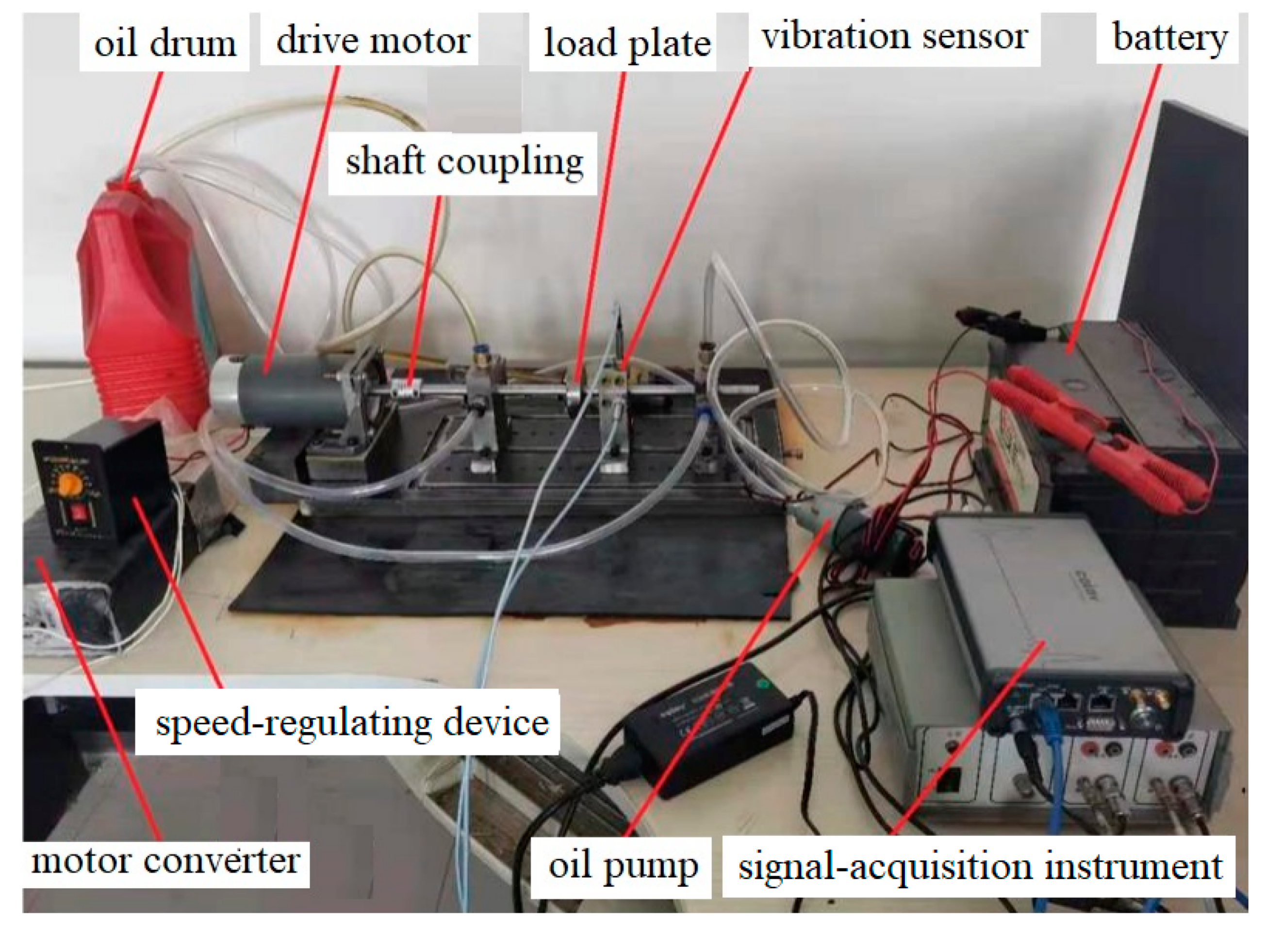
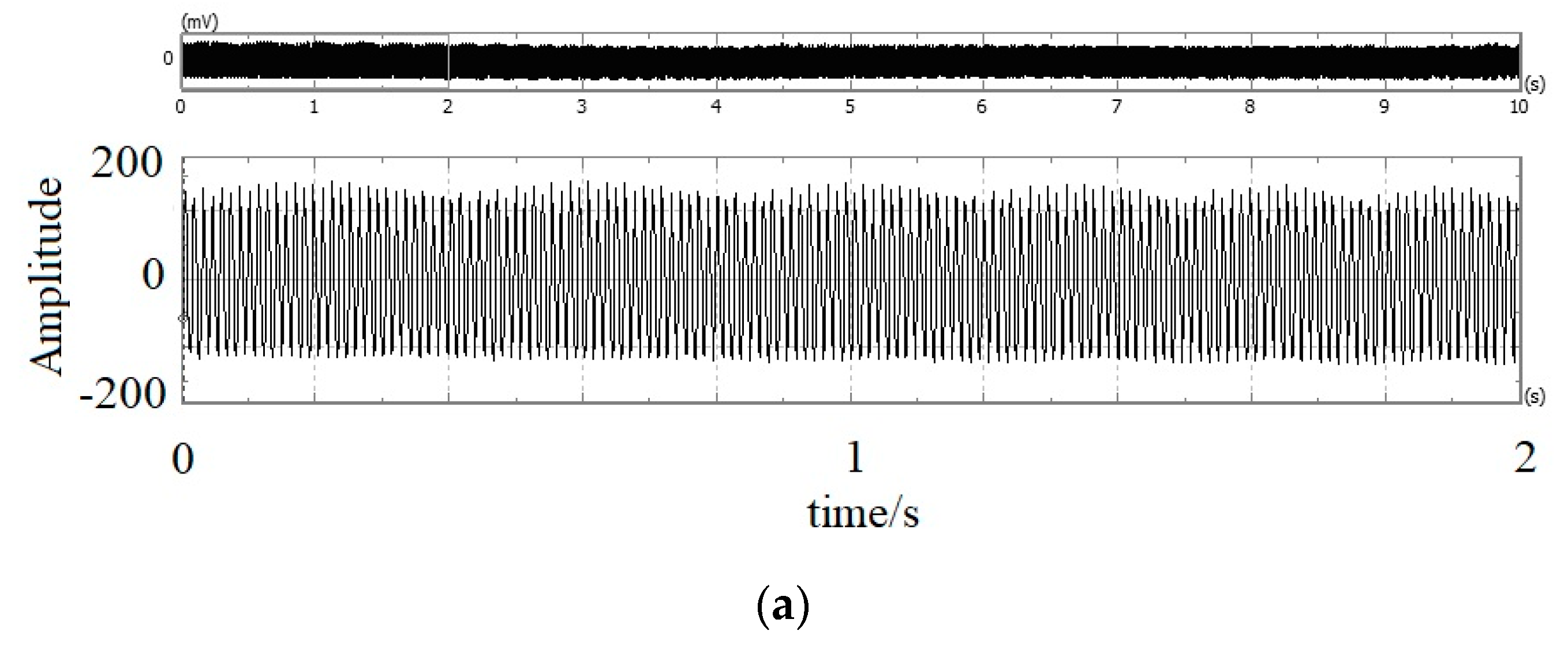
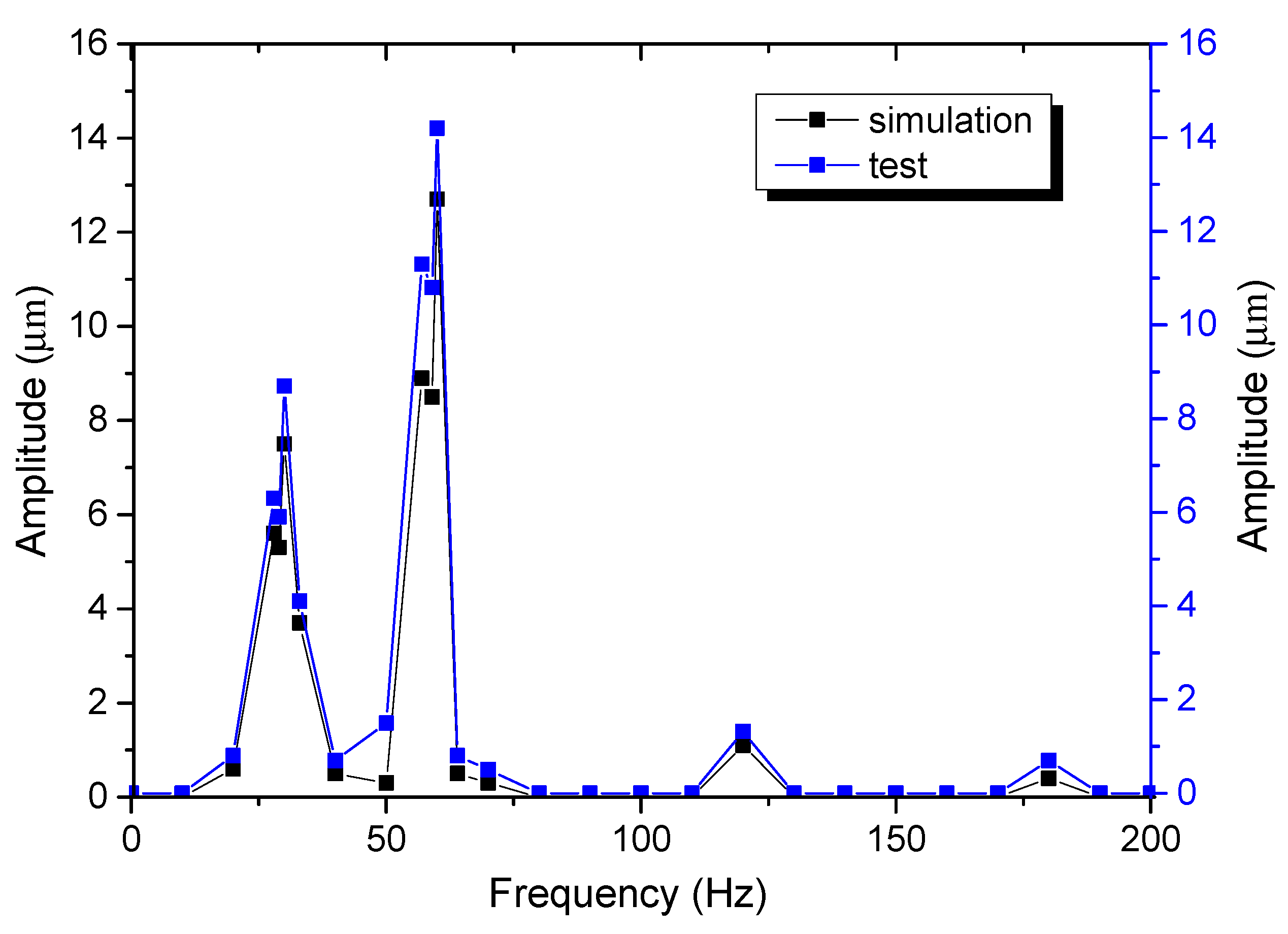
4. Experimental Verification

According to the simulated experimental model, the test-bed of the floating ring rotor system is presented, as shown in Figure 10. It is composed of drive motor, coupling, rotating shaft, oil pump, battery and other components. The dynamic response of the system under a certain clearance ratio is tested.
Through the above test-bed, the dynamic response of the floating ring rotor is tested when λ = 0.01 and speed ratio is S = 1, and the time-domain response, spectrum diagram, axis trajectory and other results of the rotor system are obtained, as shown in Figure 11. Under this parameter condition, the time-domain signal of the floating ring rotor is a periodic signal. According to the spectrum analysis, its component is only the power frequency signal component of the rotor, which is consistent with the calculation result in Figure 6. Compared with the simulation diagram, it shows the correctness of modeling of simulation calculation.
The experimental results show that, under the condition of small internal oil film to shaft clearance ratio (λ = 0.01, S = 1), the floating ring rotor system makes single-cycle simple harmonic motion. From the spectrum diagram (Figure 11b), it can be seen that its vibration component is mainly a speed frequency signal; the double frequency signal is very small and can be ignored. The rotor axis trajectory is elliptical and works normally.
When λ= 0.01 and speed ratio is S = 1.58, the time-domain response, spectrum diagram, axis trajectory and other results of the rotor system are obtained, as shown in Figure 12. Under this parameter condition, there is an obvious frequency-doubling signal and a half-frequency vortex phenomenon. The time-domain signal of the floating ring rotor is a half-periodic signal. According to the spectrum analysis, its component is only the power frequency signal component of the rotor, which is consistent with the calculation result in Figure 7.
From the test results in Figure 13, it can be seen that, in the case of λ = 0.035 and S = 1, the nonlinear vibration of the floating ring rotor system is significantly enhanced, and there is an obvious half-frequency whirl signal, which is mainly caused by the improper clearance ratio of the floating ring bearing. The test results are consistent with the simulation calculation conclusion in this study.
In order to verify the correctness of the dynamic model of the floating ring bearing-rotor system and calculation simulation, dynamic model of the floating ring bearing-rotor system is established in this study. The relative clearance ratio of the structural parameters of the floating ring is λ = 0.01, and the relative rotate speed of the rotor system is S = 2.47. The test bench shown in Figure 10 was used to test the amplitude characteristics of the position of the mass disk, and compare with the calculation results to verify the reliability of the settlement results.
It can be seen from the comparative analysis in Figure 14 that the vibration characteristics of the test are consistent with the simulation results, and the system has quasi-periodic characteristics at high speed, which is consistent with the calculation results in Figure 9d. At the same time, the test amplitude peak is larger than the simulation peak, and the maximum error is about 9.3%, which may be caused by the accuracy of the measuring instrument. The vibration amplitude of the test result is larger than the simulation value, which may be caused by the mass eccentricity of the system.

5. Conclusions

In this study, the transfer-matrix method was used to develop the dynamic model of the floating ring bearing-rotor system, aiming at the vibration problem of the floating ring bearing-rotor system. The dynamic model of the floating ring bearing-rotor system was presented, and the influence of the relative clearance of internal oil film on the vibration characteristics of rotor system was studied. Using the Runge–Kutta numerical calculation method, the dynamic characteristics of the system under different parameters were calculated, and the ideal clearance ratio was obtained through comparative analysis, which provides an important reference for the design and application of turbocharger floating ring rotor size structure. When the relative clearance of the floating ring bearing-rotor is λ = 0.01, the vibration characteristic of the system is best.
(1) It can be seen from the calculation results that with the increase in the relative clearance of the floating ring bearing rotor, the range of steady operation (single cycle) decreases gradually, from 0 < S < 1.6 to 0 < S < 0.66.
(2) When relative clearance is a smaller amount (λ = 0.01), stable working range is larger, which can meet the work requirements of the rotor system; however, the relative gap is too large (λ = 0.075), the oil-film oscillation will increase under the condition of high speed, and the rotor unstable speed begins to reduce greatly.
(3) For the design of the floating ring bearing-rotor system, beyond considering the appropriate clearance ratio selection of the floating ring bearing, the relative gap must also be appropriate, with equivalent structure parameters of floating in design, with the appropriate relative clearance volume of about λ = 0.01.

Author Contributions

L.P. participated in the design of the study, helped to prepare the computational model and performed the computational analysis, H.Z. conceived of the study, and participated in its design and coordination and drafted the manuscript, Z.S. participated in the dataset preparation and helped to draft the manuscript. All authors have read and agreed to the published version of the manuscript.

Funding

This research is funded by the National Natural Science Foundation of China with number 51875166, and Key Projects in Hebei Province with number 20310806D.

Institutional Review Board Statement

Not applicable.

Informed Consent Statement

Not applicable.

Data Availability Statement

Not applicable.

Conflicts of Interest

The authors declare that they have no conflict of interest.

References

  1. Shi, W.; Wei, D.G.; Zhu, L.; Hu, M.L. Study on effects of clearance ratio of inner to outer oil film on turbocharger rotor instability. Chin. J. Auto. Eng. 2014, 33, 130–136. [Google Scholar]
  2. Huang, R.; Zhang, W.L.; Xing, W.D.; Zhang, Y. Gas excitation’s influence on dynamic behavior of a turbo-charger rotor-ball bearing system. J. Vib. Shock. 2014, 33, 140–146. [Google Scholar]
  3. Liao, A.H.; Sui, Y.F.; Wu, C.H. Dynamic characteristics analysis of turbocharger rotor based on gyro effect. Chin. Int. Combust. Engine Eng. 2009, 4, 68–73. [Google Scholar]
  4. Zhu, L.; Wei, D.G.; Shi, W. Effects of eccentricity on rotor dynamics charac-teristic of turbocharger. Chin. J. Auto. Engin. 2013, 4, 282–286. [Google Scholar]
  5. Dyk, Š.; Smolík, L.; Rendl, J. Predictive capability of various linearization approaches for floating-ring bearings in nonlinear dynamics of turbochargers. Mech. Mach. Theory 2020, 149, 103843. [Google Scholar] [CrossRef]
  6. Pei, S.; Xu, H.; Yun, M.; Shi, F.; Hong, J. Effects of surface texture on the lubrication performance of the floating ring bearing. Tribol. Int. 2016, 102, 143–153. [Google Scholar] [CrossRef]
  7. Pavel, N.; Petr, Š.; Jura, H. The effective computational model of the hydrodynamics journal floating ring bearing for simulations of long transient regimes of turbocharger rotor dynamics. Inter. J. Mech. Sci. 2018, 148, 611–619. [Google Scholar]
  8. Luboš, S.; Štěpán, D. Towards efficient and vibration-reducing full-floating ring bearings in turbochargers. Int. J. Mech. Sci. 2020, 175, 105516. [Google Scholar]
  9. Sitae, K.; Alan, B.P. Effects of thermo hydro dynamic (THD) floating ring bearing model on rotor dynamic bifurcation. Inter. J. Non-Linear Mech. 2017, 95, 30–41. [Google Scholar]
  10. Tian, L.; Wang, W.; Peng, Z. Nonlinear effects of unbalance in the rotor-floating ring bearing system of turbochargers. Mech. Syst. Signal Process. 2013, 34, 298–320. [Google Scholar] [CrossRef]
  11. Xie, Z.; Zhu, W. An investigation on the lubrication characteristics of floating ring bearing with consideration of multi-coupling factors. Mech. Syst. Signal Process. 2021, 162, 108086. [Google Scholar] [CrossRef]
  12. Papadopoulos, C.I.; Kaiktsis, L.; Fillon, M. Computational fluid dynamics thermo hydrodynamic analysis of three-dimensional sector-pad thrust bearings with rectangular dimples. J. Tribol. 2014, 136, 11702. [Google Scholar] [CrossRef]
  13. Braun, D.; Greiner, C.; Schneider, J.; Gumbsch, P. Efficiency of laser surface texturing in the reduction of friction under mixed lubrication. Tribol. Int. 2014, 77, 142–147. [Google Scholar] [CrossRef]
  14. Qiu, Y.; Khonsari, M. Experimental investigation of tribological performance of laser textured stainless steel rings. Tribol. Int. 2011, 44, 635–644. [Google Scholar] [CrossRef]
  15. Etsion, I. State of the art in laser surface texturing. J. Trib. 2009, 127, 761–762. [Google Scholar] [CrossRef]
  16. Wang, Q.J.; Zhu, D. Virtual texturing: Modeling the performance of lubricated contacts of engineered surfaces. J. Tribol. 2005, 127, 722–729. [Google Scholar] [CrossRef]
  17. Xie, Z.; Song, P.; Hao, L.; Shen, N.; Zhu, W.; Liu, H.; Shi, J.; Wang, Y.; Tian, W. Investigation on effects of Fluid-Structure-Interaction (FSI) on the lubrication performances of water lubricated bearing in primary circuit loop system of nuclear power plant. Ann. Nucl. Energy 2020, 141, 107355. [Google Scholar] [CrossRef]
  18. Xie, Z.; Shen, N.; Zhu, W.; Liu, H.; Shi, J.; Wang, Y.; Tian, W. Dynamic characteristics analysis of the hydro-hybrid liquid Sodium lubricated bearing-rotor coupled system in the two-circuit main loop liquid sodium pump system. Ann. Nucl. Energy 2019, 136, 107059. [Google Scholar] [CrossRef]
  19. Xie, Z.; Shen, N.; Ge, J.; Zhu, W.; Song, P.; Liu, H.; Hao, L.; Tian, W. Analysis of the flow noises of the nuclear main pump caused by the high temperature liquid Sodium in the two-circuit main loop liquid Sodium pump system. Ann. Nucl. Energy 2020, 145, 107550. [Google Scholar] [CrossRef]
  20. Schweizer, B. Total instability of turbocharger rotors—Physical explanation of the dynamic failure of rotors with full-floating ring bearings. J. Sound Vib. 2009, 328, 156–190. [Google Scholar] [CrossRef]
  21. Schweizer, B. Dynamics and stability of turbocharger rotors. Arch. Appl. Mech. 2009, 80, 1017–1043. [Google Scholar] [CrossRef]
  22. Tian, L.; Wang, W.J.; Peng, Z.J. Effects of bearing outer clearance on the dynamic behaviors of the full floating ring bearing supported turbocharger rotor. Mech. Syst. Signal Process. 2012, 31, 155–175. [Google Scholar] [CrossRef]
  23. Woschke, E.; Daniel, C.; Nitzschke, S. Excitation mechanisms of non-linear rotor systems with floating ring bearings—Simulation and validation. Int. J. Mech. Sci. 2017, 134, 15–27. [Google Scholar] [CrossRef]
  24. Zhang, C.; Men, R.; He, H.; Chen, W. Effects of circumferential and axial grooves on the nonlinear oscillations of the full floating ring bearing supported turbocharger rotor. Proc. Inst. Mech. Eng. Part J. J. Eng. Tribol. 2018, 233, 741–757. [Google Scholar] [CrossRef]
  25. Wen, B.C.; Gu, J.L. Advanced Rotor Dynamics: Theory, Technology and Application; Mach Press: Beijing, China, 1999. [Google Scholar]
  26. Nicholas, V.; Alan, R.C.; Balakumar, B. Nonlinear dynamics of a Jeffcott rotor with torsional deformations and rotor-stator contact. Int. J. Non-Linear Mech. 2017, 92, 102–110. [Google Scholar]
  27. Saurabh, K.B.; Anubhab, S.; Arun, K.S.; Ranjan, B. Dynamics of a rotor shaft driven by a non-ideal source through a universal joint. J. Sound Vib. 2021, 499, 115992. [Google Scholar]
  28. Kandil, A.; Sayed, M.; Saeed, N.A. On the nonlinear dynamics of constant stiffness coefficients 16-pole rotor active magnetic bearings system. Eur. J. Mech.-A/Solids 2020, 84, 104051. [Google Scholar] [CrossRef]
  29. Zeise, P.; Schweizer, B. Dynamics, stability and bifurcation analysis of rotors in air ring bearings. J. Sound Vib. 2021, 116392. [Google Scholar] [CrossRef]
  30. Capone, G.; Russo, M.; Russo, R. Dynamic characteristics and stability of a journal bearing in a non-laminar lubrication regime. Tribol. Int. 1987, 20, 255–260. [Google Scholar] [CrossRef]
  31. Adiletta, G.; Guido, A.R.; Rossi, C. Chaotic motions of a rigid rotor in short journal bearings. Nonlinear Dyn. 1996, 10, 251–269. [Google Scholar] [CrossRef] [Green Version]
  32. Orcutt, F.K.; Ng, C.E. Steady-State and dynamic prosperities of the floating-ring journal bearing. ASME J. Jubr. Technol.-Trans. 1968, 90, 243–253. [Google Scholar] [CrossRef]
  33. Zhang, H.; Shi, Z.Q.; Zhen, D.; Gu, F.S.; Ball, A. Stability analysis of a turbocharger rotor system supported on floating ring bearings. J. Physics Conf. Ser. 2012, 364, 012032. [Google Scholar] [CrossRef] [Green Version]
  34. Tian, L.; Wang, W.J.; Peng, Z.J. Dynamic behaviors of a full floating ring bearing supported turbocharger rotor with engine excitation. J. Sound Vib. 2011, 330, 4851–4874. [Google Scholar] [CrossRef]
Figure 1. Dynamic finite-element model of the floating bearing-rotor system.
Machines 09 00285 g001
Figure 2. Schematic diagram of bearing: (a) schematic diagram of floating ring bearing; (b) floating ring model.
Machines 09 00285 g002
Figure 3. Bifurcation diagram of the axis and floating ring when λ = 0.01: (a) bifurcation diagram of journal; (b) bifurcation diagram of floating ring.
Machines 09 00285 g003
Figure 4. Bifurcation diagram of the axis and floating ring when λ = 0.035: (a) bifurcation diagram of journal; (b) bifurcation diagram of floating ring.
Machines 09 00285 g004
Figure 5. Bifurcation diagram of the axis and floating ring when λ = 0.075: (a) bifurcation diagram of journal; (b) bifurcation diagram of floating ring.
Machines 09 00285 g005
Figure 6. Dynamic response of the floating ring system when λ = 0.01 and speed ratio is S = 1: (a) time-domain waveform; (b) orbit; (c) Poincare section; (d) the FFT spectrum of rotor.
Machines 09 00285 g006
Figure 7. Dynamic response of the floating ring system λ = 0.01 and speed ratio is S = 1.58: (a) time-domain waveform; (b) orbit; (c) Poincare section; (d) the FFT spectrum of the disk.
Machines 09 00285 g007
Figure 8. Dynamic response of the floating ring system λ = 0.01 and speed ratio is S = 2.25: (a) time-domain waveform; (b) orbit; (c) Poincare section; (d) the FFT spectrum of the disk.
Machines 09 00285 g008aMachines 09 00285 g008b
Figure 9. Dynamic response of the floating ring system λ = 0.01 and speed ratio is S = 2.47: (a) time-domain waveform; (b) orbit; (c) Poincare section; (d) the FFT spectrum of the disk.
Machines 09 00285 g009
Figure 10. Test diagram of the floating ring rotor test device.
Machines 09 00285 g010
Figure 11. Dynamic response of the floating ring system (test result), when λ = 0.01 and speed ratio is S = 1: (a) time-domain waveform; (b) the FFT spectrum of rotor; (c) axis trajectory; (d) waterfall diagram.
Machines 09 00285 g011aMachines 09 00285 g011b
Figure 12. Dynamic response of the floating ring system (test result), when λ = 0.01 and speed ratio is S = 1.58: (a) time-domain waveform; (b) the FFT spectrum of rotor; (c) axis trajectory; (d) waterfall diagram.
Machines 09 00285 g012aMachines 09 00285 g012b
Figure 13. Dynamic response of the floating ring system (test result), when λ = 0.035 and speed ratio is S = 1: (a) time-domain waveform; (b) the FFT spectrum of rotor; (c) axis trajectory; (d) waterfall diagram.
Machines 09 00285 g013aMachines 09 00285 g013b
Figure 14. Comparison between simulation results and test results, when λ = 0.01 and speed ratio is S = 2.47.
Machines 09 00285 g014
Table 1. Structural calculation parameters of the rotor system.
ParametersNumerical Value
Quality (kg)m1 = m3 = 0.005, m2 = 0.1078
Moment of inertia (10−6 kg·m2)Jp = 18.75, Ja = 10.62
Shaft length (mm)L1 = L2 = 36
Spindle diameter (mm)D = 7
Axis eccentric (mm)e1 = e2 = 0.002
The first critical speed (rad/s)ω0 = 2π × 692.5
Table 2. Parameters of floating ring bearing.
ParametersNumerical Value
Oil-film viscosity (Pa·s)μ = 0.01 (25 °C)
Inner and outer radius of floating ring (mm)Ri = 3.5; Ro = 6.5
Floating ring length (mm)L = 7.6
Floating ring mass (g)m = 6.7
Moment of inertia (10−6 kg·m2)I = 0.28
Publisher’s Note: MDPI stays neutral with regard to jurisdictional claims in published maps and institutional affiliations.

