1. Introduction
The diagnosis of electrical motors out of their stray (escaping the chassis) magnetic field was up until recently focused mainly on large, high-power motors. The main reasons were the high field strength and the size of the motors. Therefore, a simple sensing coil with easily modifiable sensitivity could be used. With smaller motors, however, the magnetic field is physically changing at a smaller scale, which makes the measurement sensitive to the background, noise, size, and exact positioning of the sensing element and requires much more precise measurement techniques. This applies to the whole dynamics of the motor and makes all measurements, control, and parameter analysis harder [
1,
2]. It follows that these kinds of external diagnosis methods would be beneficial over classical invasive approaches for diagnosis and fault detection, which require disassembly or dedicated internal sensors. Due to the miniaturization advances in sensors and microelectronics, the diagnostic of small electrical motors comes into the scientific and engineering focus as it became technologically feasible. With the progress in further automation of manufacturing processes comes the need to invent new diagnostic methods that will be easily applicable on a production line in an automated way.
During the last decade, the main research focus was put on three-phase motors, which can be seen from the research conducted in the field of fault diagnostics [
3,
4,
5]. Given the sinusoidal character of the magnetic fields, the most dominant method used is the analysis of the magnetic field in the frequency domain. Less attention is paid to small inductive motors [
6] or electrically commutated Permanent Magnet Synchronous Motors (PMSM) [
7]. However, we were unable to find any relevant publication in the fault diagnostics out of the stray magnetic field for direct current (DC) brushed motors. It appears that little to no attention is paid to this topic, though there is a need in the industry for further advances. Among the most examined phenomena are short-circuits in a defective winding [
4,
8,
9] or the influence of load changes [
10,
11]. Recent experiments with the use of the stray field for BLDC motor commutation under varying load torque can be found in [
12,
13].
One of the problems at hand is the detection of the rotation direction of small DC motors. These types of motors are cheap to manufacture and find their use in a wide variety of products. Though cheap, there are products in which the replacement of a faulty motor can lead to excessive expenses. One such example can be a fuel pump used in combustion engine cars. Once built into a fuel tank and installed in a car coming out of the production line, finding a faulty piece comes with high costs. Yet, incorrect direction rotation caused by swapped wiring is a common manufacturing fault.
There exists an industrial sensor capable of detecting the rotation direction of a brushed DC motor based on the measurement of changes of the stray magnetic field escaping from the gaps between stator magnets. However, the results from the sensor are highly dependent on the exact position of the sensor, which might not lead to a reliable solution to the problem.
Existing diagnosis methods, which utilize the stray magnetic field of a motor, can be divided into two basic subgroups of model-based and data-driven methods [
3,
7]. The model-based methods work based on a dynamic model of the system, which predicts its behavior and compares the predictions with measured data. The data-driven methods, on the contrary, compare the measurements with previously measured data, which are known to represent specific correct or faulty states of the diagnosed system. While both approaches have their advantages and disadvantages, this paper deals primarily with the data-driven approaches.
The goal of this work is to develop and experimentally verify a novel method of the DC motor rotation direction detection using an affordable magnetic flux density sensor, while automating the process of the magnetic field analysis and at the same time locating a suitable position for the sensor during the measurement of a given motor.
To the best of our knowledge, no similar experimental work has been conducted in the field of the detection of the rotation direction out of the stray magnetic field. From the research in scientific publications, it seems that the problem of analysis of small direct current motors out of their stray magnetic field receives little attention from researchers.
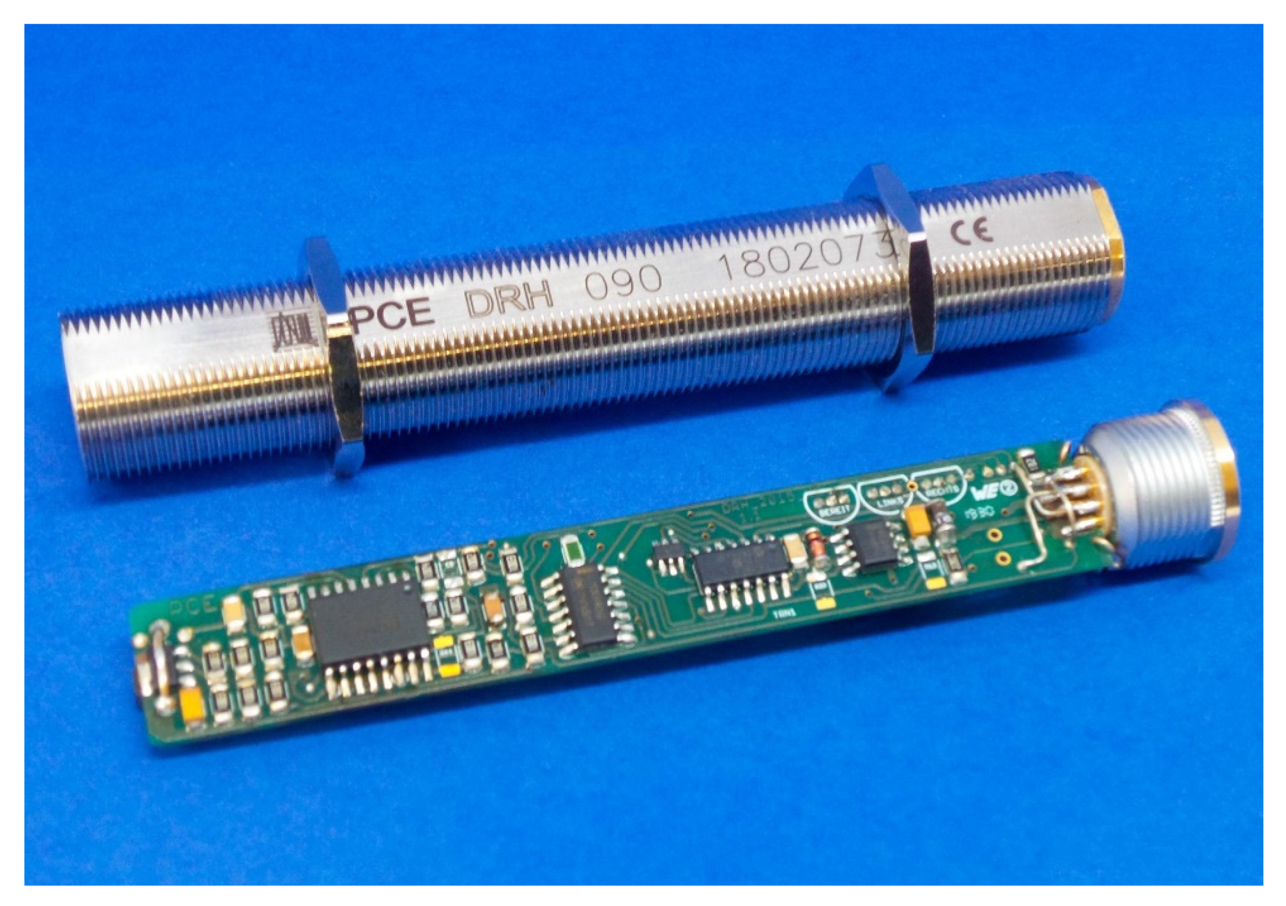
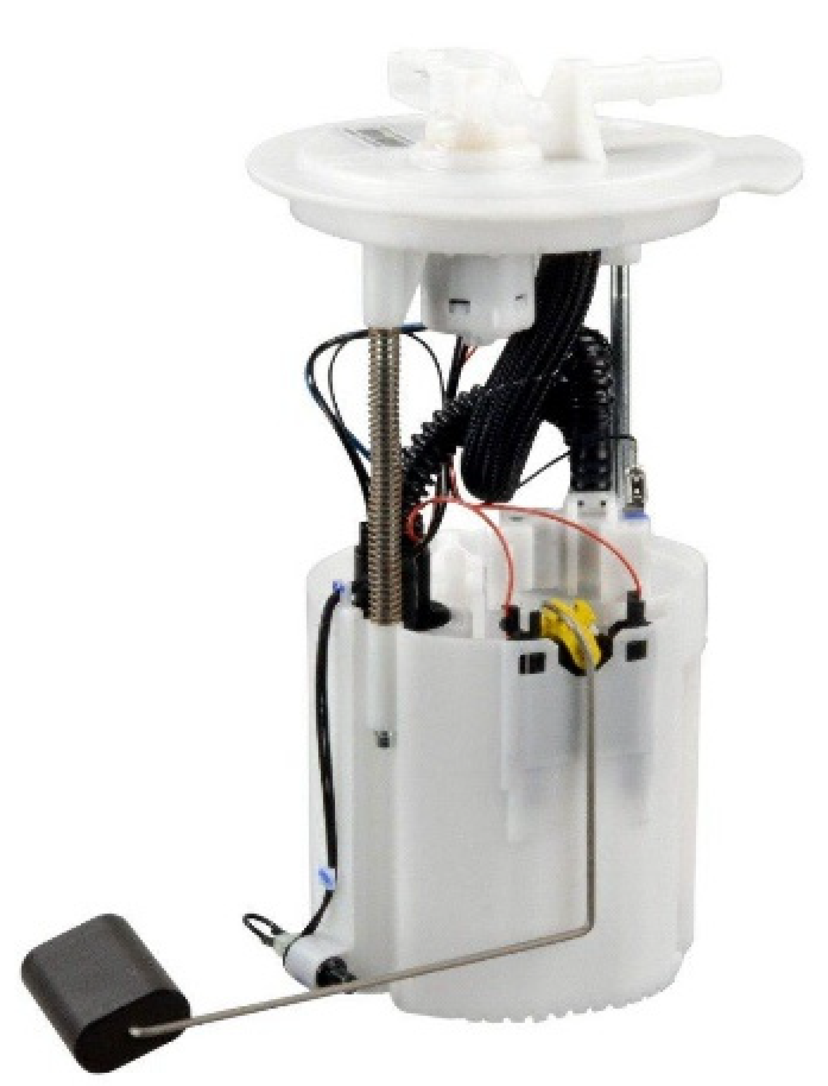
Existing Sensor for Detection of the Rotation Direction
Only a few sensors for the detection of rotation direction out of the stray magnetic field of a brushed electric motor exist, mainly produced by German company Process Control Electronic GmbH [
14]. One of the sensors can be seen in
Figure 1.
The rotation direction sensors can be used with three-phase AC or brushed DC motors. For the purpose of this article, only the latter variant will be considered further. The measurement is very simple, as the sensor compares the values of magnetic flux density before and while supplying the motor, effectively comparing the average values of the static field with the average value of the rotating field. The sensor must be placed within a given proximity to the gap between stator magnets and with a given orientation (there are more construction variants for different sensor orientations) [
15].
There is a magnetic field escaping the motor’s body from the gap between the stator magnets. In this area, the stray magnetic flux density is the strongest. However, the magnetic field lines diverge on both sides along with the motor housing, to subsequently close in the gap between the stator magnets on the other side of the motor (see section Experimental Results for more details).
2. Detecting the Rotation Direction of a Brushed DC Motor
Based on our experience from previous experiments, we proposed a novel, non-invasive method that can detect the rotation direction of a DC motor shaft based on the measurement of its stray magnetic field, which would be simple enough to be easily implemented in industrial applications.
As the method is data-based, it requires a reference measurement of the correct state of the motor. All required measurements can be done using a 3-axis magnetic flux density sensor with suitable range and sampling. In the following text, by “taking a measurement” we mean:
Placing the sensor in a suitable location (explained further in the following sections) within near proximity of the motor chassis.
Applying voltage to the motor and letting the angular velocity of the rotor stabilize.
Measuring the level of magnetic flux density. As it is expected to oscillate around a certain value due to the motor construction, it is preferable to take the average value from a high frequency sampling over a longer period to filter out these oscillations, noise, and the effects of coil commutation.
All measurements are taken with the same voltage level applied to the motor either with positive or negative polarity. The voltage level needs to be chosen such that the motor is spinning as fast as possible, while not posing a risk of causing damage to the motor in either direction.
2.1. Reference Image
Before the application of the diagnostic technique in a large-scale manufacturing process, we need to acquire the reference image of the magnetic flux difference vector
according to Equation (1).
where
(T) is the magnetic flux density measured with positive voltage applied to the motor and with the shaft rotating in the correct direction, and
(T) is the magnetic flux density with negative voltage applied to the motor and with the shaft rotating in the incorrect direction, meaning the
and
represent the OK and NOK states of the motor, respectively.
2.2. Application
Later, when the method is applied to test a newly manufactured motor for correct direction of rotation, again take the
and
measurements for the testing. Calculate the difference vector
according to Equation (2), this time not knowing whether the motor is wired correctly and therefore is spinning in the correct direction or not.
To diagnose if the motor is in the OK or the NOK state, we use the cosine of the angle between the reference vector
and the measured
, computed according to Equation (3).
If we choose a threshold value K (we suggest , corresponding to 45°), three outcomes are possible:
motor is OK.
motor is NOK.
the result cannot be determined, and the process should be repeated.
The magnetic flux density measured outside the motor chassis consists mainly of two parts: the static magnetic field induced by the stator magnets and the background, and the magnetic field induced by the rotor coils. The static part does not change with the rotation direction, but the rotor-induced part does. In theory, since we are subtracting the vectors for both rotation directions (eliminating the static field), the difference vector should point in the same direction as the reference vector if the motor is OK and directly in the opposite direction if the motor is NOK, which makes this approach less sensitive to noise and other corrupting factors.
Advantages of the proposed method are:
Very simple in principle and execution.
The influence of background magnetic induction is negated, assuming it is static during the measurement.
The result and measurement values have a clear physical dimension.
Robust evaluation of the result.
Disadvantages of the proposed method can be:
The requirement of knowing the reference vector for the result evaluation.
Sensitive to unstable magnetic background.
Proper measurement location needs to be determined.
2.3. Optimal Measurement Location
The proposed method of detection of the rotation direction strongly depends on the exact location chosen for the taking of the measurements. As it relies on the reference vector , the only criteria suitable to choose the correct location is its length . To acquire some insights on how to choose the measurement location for a specific motor and to put the method to a test, we developed custom measuring equipment and measured the stray magnetic field surrounding a fuel pump DC motor, which is covered in the following sections.
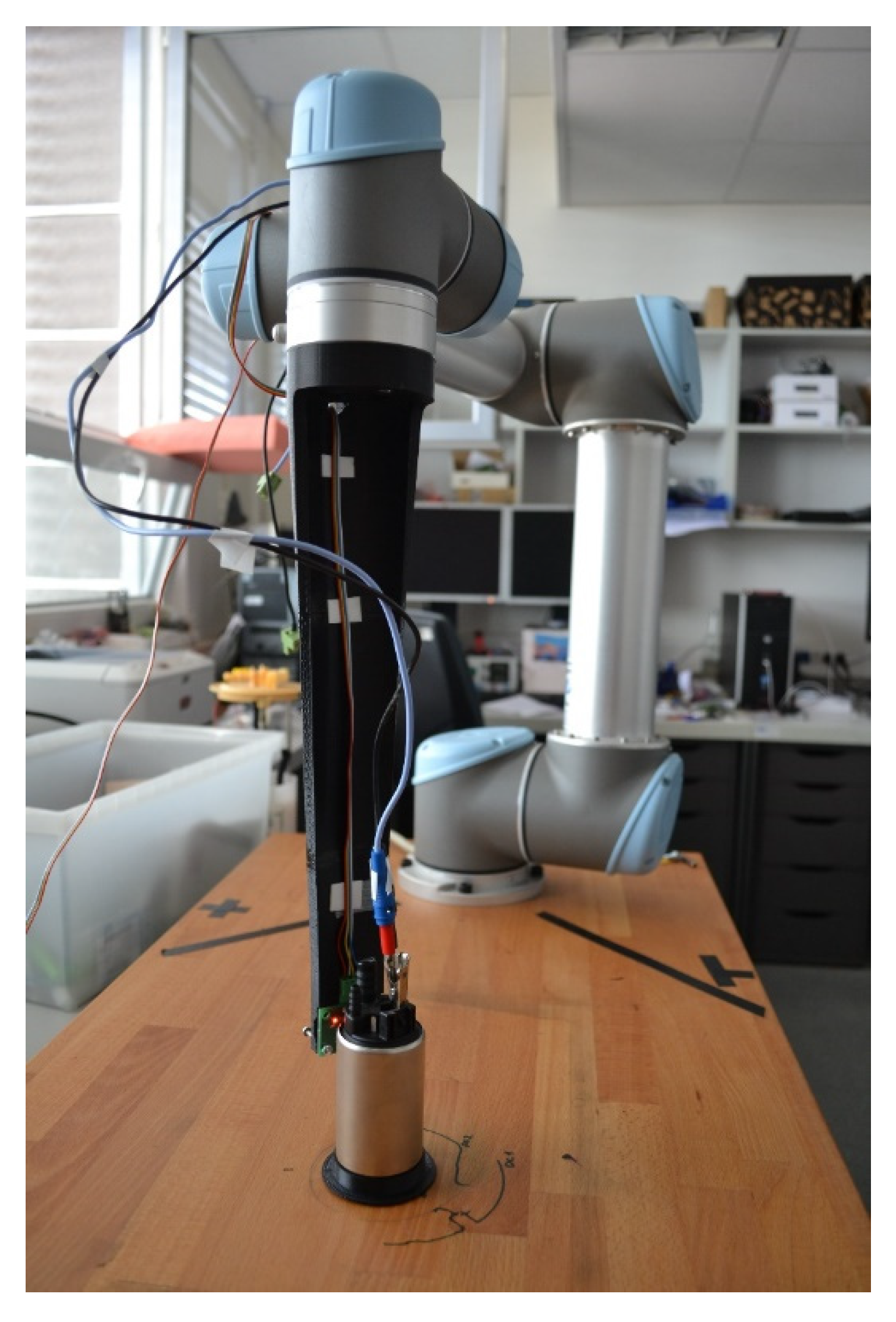
3. Experimental Setup
To conduct the experiment, we used a Universal Robots UR10e [
16] collaborative robot. It is a 6 DOF manipulator for a wide range of automated applications, with an option of TCP/IP interface, that can be used to control the robotic arm. It enabled the fast development of a measurement station suiting the needs of a three-dimensional magnetic field measurement around an electric motor.
To take the measurements of the stray magnetic flux density in a cylindrical envelope surrounding the measured motor simple for the robotic arm, a plastic holder for sensors was prototyped and 3D printed (see
Figure 2). This also kept the electromagnetic noise emerging from the motors of the robot to a minimum.
The experimental setup consisted of:
3.1. Sensors
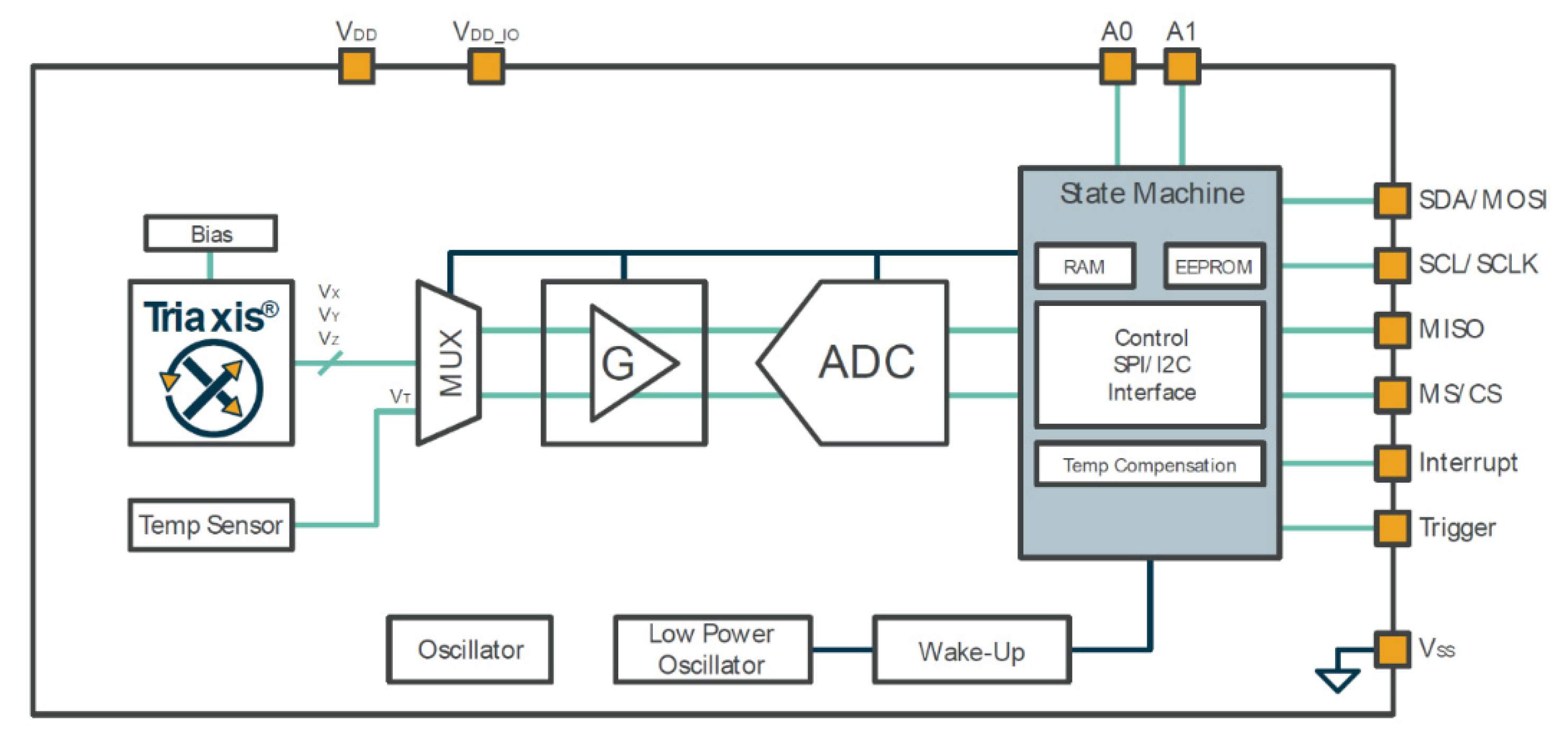
Three-axis Hall-effect sensor MLX90393 [
17,
18], which has a schematic depicted in
Figure 3, was chosen as the sensing element, mainly for its high sensitivity and compactness. It is an integrated circuit sensor with a high dynamic range (5–50 mT), configurable sampling frequency (from 259 µs to 66.6 ms conversion time for a single axis), and high sensitivity (0.161 µT/LSB for
x,
y-axis, and 0.294 µT/LSB for
z axis) that allows for measurements with a wide range of motor sizes.
Internally, the sensor senses the Hall-effect voltage on 3 elements, each effective in one axis. The signals are amplified and digitalized with internal ADC and stored in internal 16-bit registers. The sensor also comes with many customizable settings, such as on-board filtering, different acquisition triggering modes, adjustable sampling rate, or single measurement mode. Thanks to these features, it can be fine-tuned to best serve the intended application.
For the purposes of our application, we used the I2C interface, which comes with the additional benefit of having multiple sensors on the same bus, thanks to the possibility of changing the device’s address by defining the logical level of A0 and A1 pins.
The sensitivity of the sensor was set to maximum (0.161 µT/LSB for
x,
y-axis, and 0.294 µT/LSB for
z axis) with the output data rate set to 493 Hz, which translates to 1.84 ms conversion time for all 3 magnetic flux density axes. As the setting of the used sensor is not trivial, please refer to the datasheet [
18] for specific timing, sensitivity, and sampling options available.
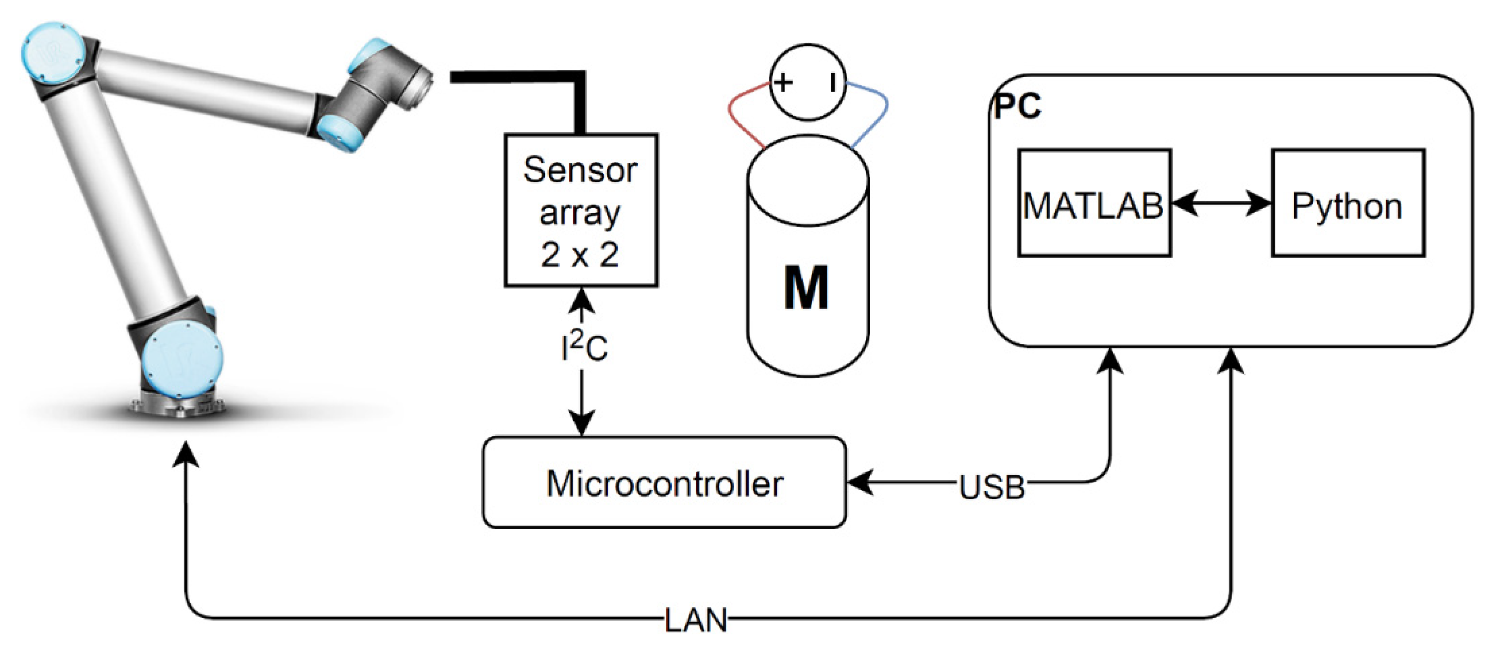
3.2. Software
The measurements were controlled by a custom-made MATLAB script with the use of MATLAB Toolbox for UR Manipulators developed at the United States Naval Academy [
19]. The toolbox consists of MATLAB functions for controlling the robot and of a local server service written in Python, that provides a communication interface between MATLAB and the UR10e through a TCP/IP connection.
Measurement Procedure
For each measurement, the MATLAB script generates a new set of cylindrical coordinates αRZ (the center of the coordinate system is placed in the motor axis of rotation), and a corresponding set of joint coordinates for the robotic arm.
The measurement was conducted in the following ranges:
α < 0°; 360° > with 1° step,
R < 60 mm; 80 mm > with 5 mm step,
Z < 0 mm; 120 mm > with 5 mm step.
After running the control script and thus starting the measurement process, the coordinates for the next measurement point are sent to the manipulator and when the position is reached, a command to take a single measurement is sent to the sensors. The measured values are read-out by the MCU and sent via UART-USB to the host PC. The control script reads the data and stores them in the workspace. This sequence is repeated for the complete measurement procedure, i.e., for all the measurement points.
In each measurement point, data from four sensors in all three axes were acquired at the same time (see the experimental setup schematic in
Figure 4). In the results section below, the data presented are a mean value from all four sensors in every given measurement point.
4. Results
4.1. Experimental Results
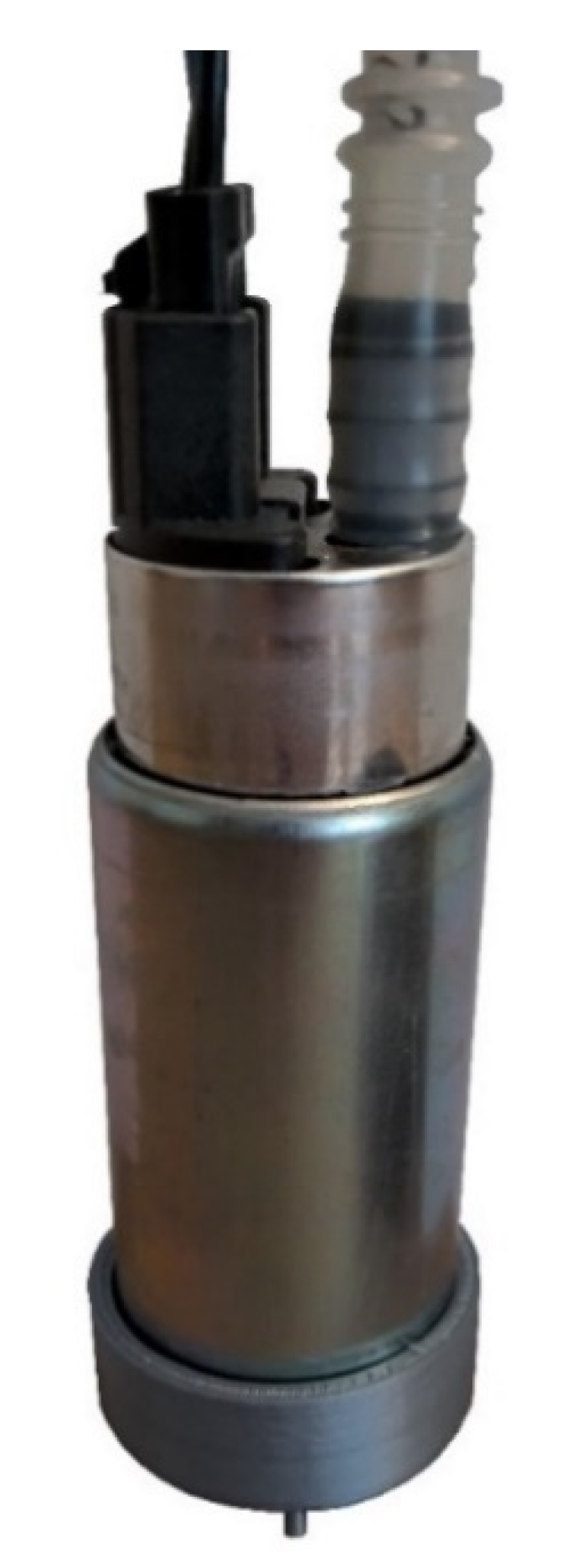
The series of measurements were conducted with a 2-pole, DC brushed motor with permanent stator magnets. The motor type that was measured, shown in
Figure 5, is commonly used in fuel pumps in the automotive industry. The dimensions of the motor are
d = 38 mm,
l = 87 mm, with a rated nominal supply of 12 V. For the experiment, supply voltage of +/− 5 V was applied, leading to 1420 RPM of the motor.
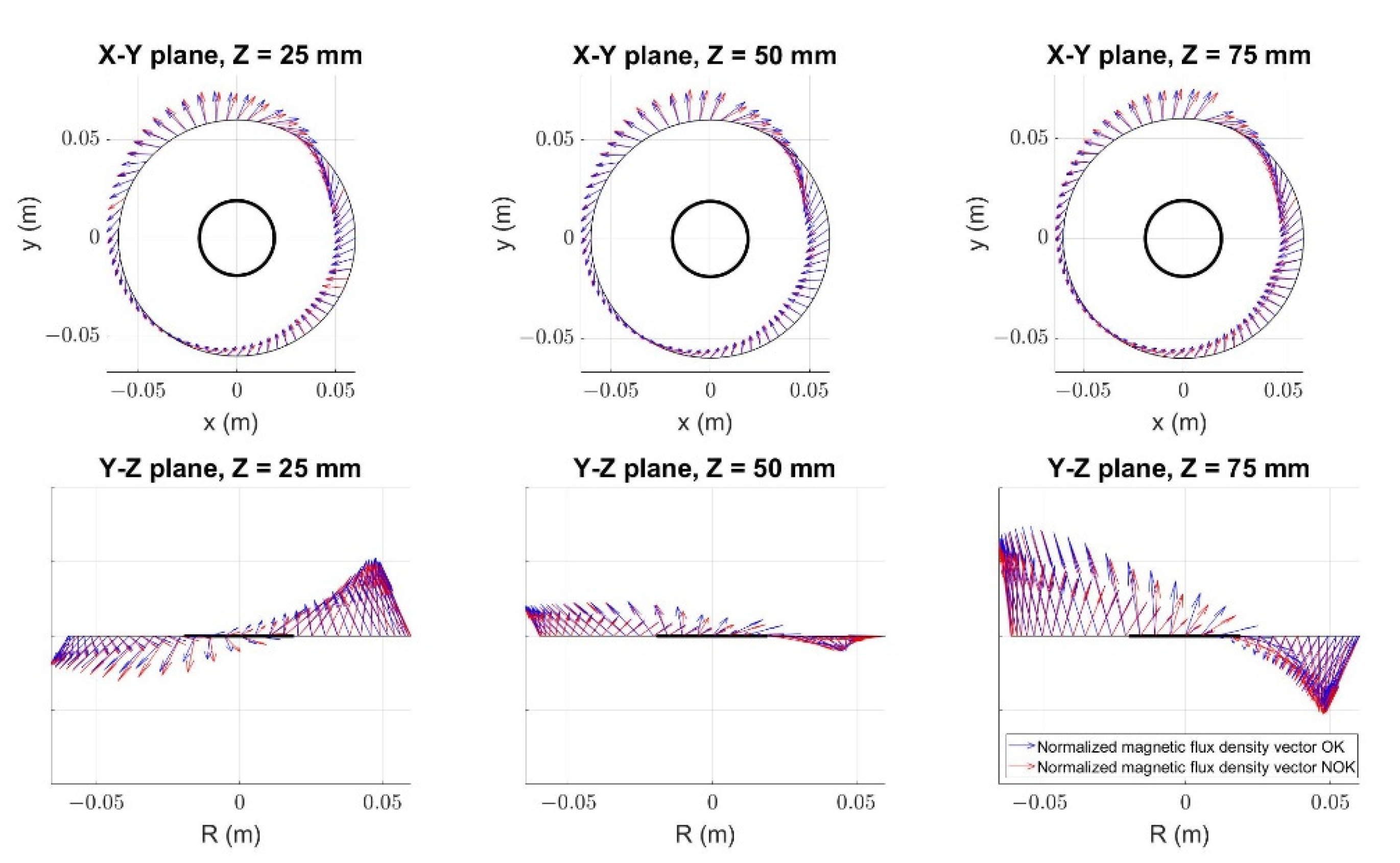
At first, we looked at the magnetic flux density escaping the measured motor chassis (low pass filtered with the sensor used), while the motor was running at a constant speed, in both directions.
The correct rotation direction is marked as OK and the opposite direction as NOK. For visual simplification, the measured data are presented in 3 horizontal planes (z-axis) and from 3 radiuses (60, 65, 70 mm). The MATLAB function quiver3 was used to produce vectors with automatic scaling turned on. Therefore, the size of the vectors represents their relative amplitude in each given plot, not the absolute measured values. The goal of the following figures is to understand the field orientation, not its magnitude in the measured points.
As can be observed from the above
Figure 6, both magnetic fields appear to be strongly similar in their orientations. Looking into the measurement data points, it appears that the amplitudes of the vectors for OK and NOK rotation directions magnetic fields are also similar. However, a shift between the measured fields can be noticed.
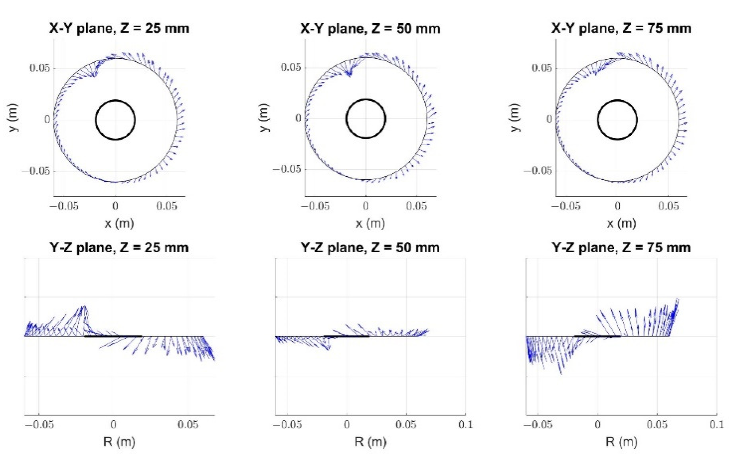
By calculating and visualizing the vector field of the reference vector
, the information about the rotation direction is revealed in
Figure 7 and
Figure 8.
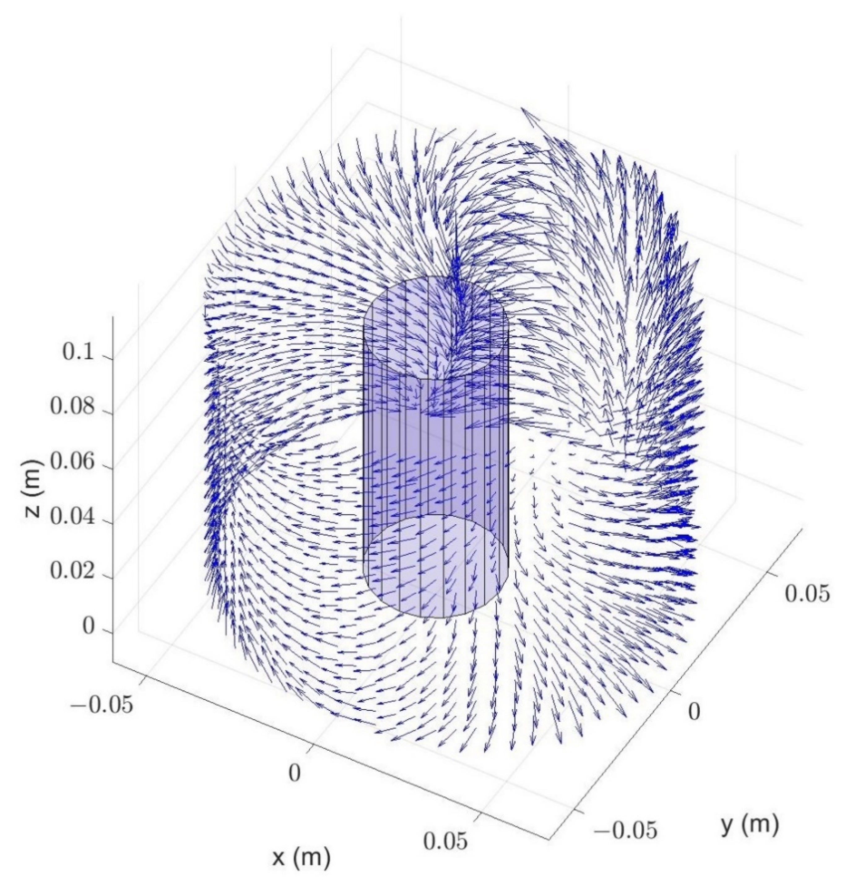
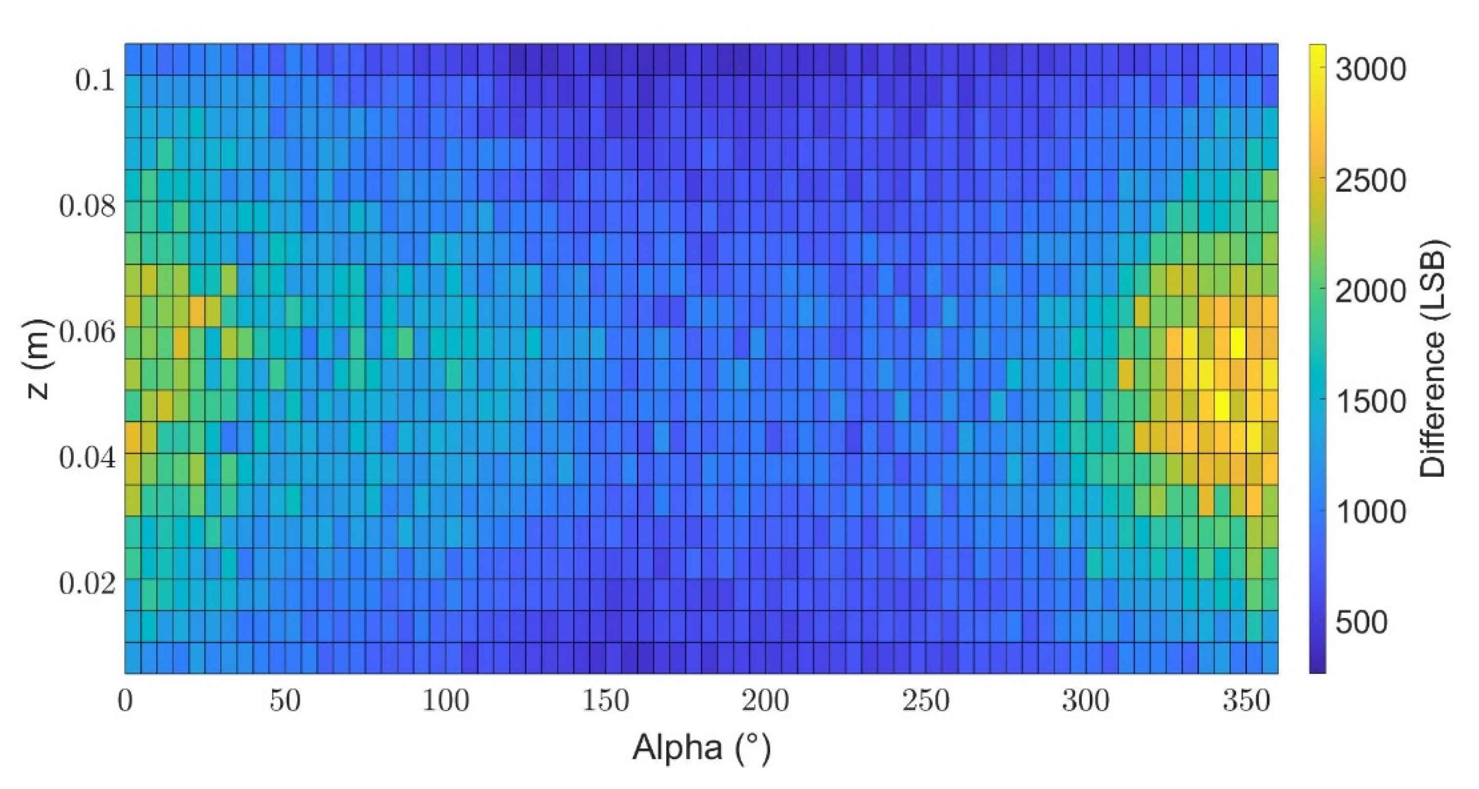
4.2. Choosing Optimal Measurement Point
As was stated earlier, the suitability of the measurement locations for the algorithm application can be determined from the size of reference vector
.
Figure 9 visualizes the scalar field
at constant radius
. The field clearly reveals one location, corresponding with one of the gaps between stator magnets, which is much more suitable for direction detection.
4.3. Application of the Proposed Method in the Chosen Area
We obtained a reference differential vector field
and discovered the most suitable area for a measurement from the noise tolerance and result reliability points of view. From
Figure 9, it is apparent that this area can be found at around
Alpha = 360° and
z = 0.05 m.
Another motor of the same type was set for a measurement with the goal of determining in which direction the motor rotates. To demonstrate the robustness of the method, a motor that is built into a plastic fuel module was chosen—see
Figure 10.
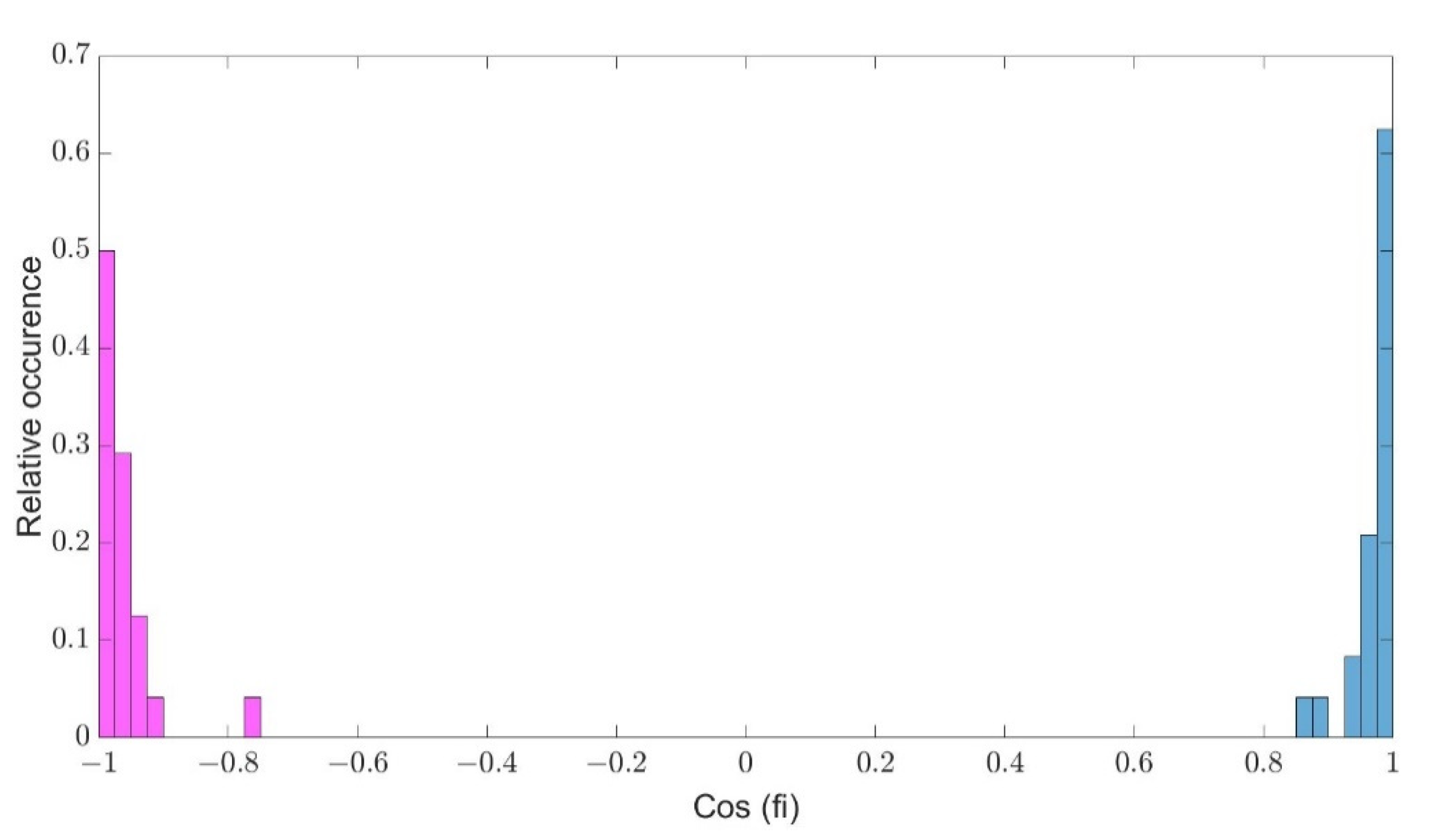
The robotic arm was set to place the sensor board as close to the chosen area as possible from the outside of the plastic module. A short series of 6 measurements with both voltage polarities was made. The measurements were repeated with small variations in the sensor position (±3–5 mm) around the optimal location.
Figure 11 shows the comparison of vectors
measured by all four sensors on the sensor board (located in 5 × 5 mm grid, marked with blue and purple colors) with the respective reference vector
(yellow color) in the measurement point.
As described earlier, the proposed algorithm calculates the angle between
and
to determine the rotation direction. The resulting angle cosines are plotted in the bar histogram in
Figure 12. The functionality and robustness of the proposed method is demonstrated by the margin (gap) in between the group of results for the rotation in both directions.
5. Conclusions
A novel method for the detection of the rotation direction of brushed DC motors from the stray magnetic field was developed. It is a very simple, easy to conduct, non-invasive method that is suitable for large-scale automation. The way the motor is connected, i.e., in which direction it was rotating can be determined by simply rotating the measured motor in both directions. The only requirements are knowing the reference of the stray magnetic field of the examined type of motor before taking the measurement and a suitable location of the measurement. This is much more suitable for application on production lines as opposed to standard methods which require the tested motor to be tested in conditions similar to its intended application, e.g., the fuel pump needs to be tested on a fluid to see if it is pumping correctly, which is impractical and takes much longer.
There is a commercially available sensor for this type of measurement. However, its documentation points towards a specific position of the sensor, i.e., the gap between the stator magnets. As the results show, the area close to the gap is prone to measurement errors as the magnetic flux density vectors split here into two directions along the sides of the motor’s body. This finding confirms our experience concerning the difficulties of measurements with the presented commercial sensor. Given the restrictions in the placement of the sensor and the instability in the provided results, it was proven that our method shows significant enhancements in the reliability of the detection of the measured motor’s rotation-direction.
To conduct the presented measurements, an experimental measurement station was set up, utilizing a 6DOF robotic arm UR10e from Universal Robots. The measurement station was presented as an example of utilizing an available robotic arm for specialized measurement. The whole setup, including additional electronics and control script, was presented.
According to
Figure 9, it seems that our presented method should provide reliable results in a larger area than the one defined for the compared commercial sensor. It might also be possible to further enlarge the suitable area significantly. Improving the functionality and robustness of the method in the whole area around the measured motor is going to be the object of follow-up research. Furthermore, preliminary results suggest that there may exist a similar method for EC motors, which will also be addressed in our future work. Further research could also be directed in applying similar non-invasive approaches for detecting other types of faults, e.g., faulty bearings, other types of motor winding defects, etc.
A side benefit of this experimental paper is the measurements of the stray magnetic field around a real DC motor, which can serve as a basis for further research into other design and diagnostic methods.
Author Contributions
Conceptualization, M.M. and R.G.; methodology, M.B. and M.A.; software, M.M.; validation, M.A., M.M. and R.G.; formal analysis, R.G. and M.A.; investigation, M.M. and M.B.; data curation, M.A.; writing—original draft preparation, M.M. and M.B.; writing—review and editing, M.B., M.M., and R.G.; visualization, M.A.; supervision, R.G.; project administration, M.B. and R.G.; funding acquisition, R.G. All authors have read and agreed to the published version of the manuscript.
Funding
This research was funded by the Faculty of Mechanical Engineering, Brno University of Technology under the project FSI-S-20-6407 “Research and development of methods for simulation, modelling a machine learning in mechatronics”.
Institutional Review Board Statement
Not applicable.
Informed Consent Statement
Not applicable.
Data Availability Statement
Conflicts of Interest
The authors declare no conflict of interest.
References
- Najman, J.; Brablc, M.; Rajchl, M.; Bastl, M.; Spacil, T.; Appel, M. Monte Carlo Based Detection of Parameter Correlation in Simulation Models. In Mechatronics 2019: Recent Advances Towards Industry 4.0; Springer: Cham, Switzerland, 2020; pp. 54–61. [Google Scholar] [CrossRef]
- Brablc, M.; Sova, V.; Grepl, R. Adaptive feedforward controller for a DC motor drive based on inverse dynamic model with recursive least squares parameter estimation. In Proceedings of the 2016 17th International Conference on Mechatronics—Mechatronika (ME), Prague, Czech Republic, 7–9 December 2016; pp. 1–5. [Google Scholar]
- Pusca, R.; Romary, R. Advances in diagnosis of electrical machines through external magnetic field. In Proceedings of the 2015 7th International Conference on Electronics, Computers and Artificial Intelligence (ECAI), Bucharest, Romania, 25–27 June 2015; pp. 5–12. [Google Scholar]
- Rigoni, M.; Sadowski, N.; Batistela, N.J.; Bastos, J.P.A.; Nau, S.L.; Kost, A. Detection and analysis of rotor faults in induction motors by the measurement of the stray magnetic flux. J. Microw. Optoelectron. Electromagn. Appl. 2012, 11, 68–80. [Google Scholar] [CrossRef]
- Pusca, R.; Romary, R.; Ceban, A.; Brudny, J.-F. An Online Universal Diagnosis Procedure Using Two External Flux Sensors Applied to the AC Electrical Rotating Machines. Sensors 2010, 10, 10448–10466. [Google Scholar] [CrossRef] [PubMed]
- Fedida, V.; Rouve, L.-L.; Chadebec, O.; Garbuio, L.; Lemaitre, S.; Tollance, T.; Weber, L. Stray magnetic field analysis applied to the internal unbalances diagnosis of low power single phase induction motor. In Proceedings of the 2016 XXII International Conference on Electrical Machines (ICEM), Lausanne, Switzerland, 4–7 September 2016; pp. 2352–2358. [Google Scholar]
- Szulim, P.; Gontarz, S. Using the Surrounding Magnetic Field in Diagnosis of the BLDC Motor. J. Electr. Eng. 2015, 66, 193–198. [Google Scholar]
- Spyropoulos, D.V.; Gyftakis, K.N.; Kappatou, J.; Mitronikas, E.D. The influence of the broken bar fault on the magnetic field and electromagnetic torque in 3-phase induction motors. In Proceedings of the 2012 XXth International Conference on Electrical Machines, Marseille, France, 2–5 September 2012; pp. 1868–1874. [Google Scholar]
- Cabanas, M.F.; Pedrayes, F.; Melero, M.G.; Garcia, C.H.R.; Cano, J.M.; Orcajo, G.A.; Norniella, J.G. Unambiguous Detection of Broken Bars in Asynchronous Motors by Means of a Flux Measurement-Based Procedure. IEEE Trans. Instrum. Meas. 2011, 60, 891–899. [Google Scholar] [CrossRef]
- Liu, Z.; Tian, G.; Cao, W.; Dai, X.; Shaw, B.; Lambert, R. Non-invasive load monitoring of induction motor drives using magnetic flux sensors. IET Power Electron. 2017, 10, 189–195. [Google Scholar] [CrossRef] [Green Version]
- Grepl, R.; Matejasko, M.; Bastl, M.; Zouhar, F. Design of a fault tolerant redundant control for electromechanical drive system. In Proceedings of the 2015 21st International Conference on Automation and Computing (ICAC), Glasgow, UK, 11–12 September 2015; pp. 1–6. [Google Scholar]
- Sergeant, P.; Hofman, I.; van den Bossche, A. Magnetic stray field based position detection in BLDC outer rotor permanent magnet synchronous machines. Int. J. Numer. Model. Electron. Netw. Devices Fields 2014, 27, 544–554. [Google Scholar] [CrossRef]
- Sova, V.; Chalupa, J.; Grepl, R. Fault tolerant BLDC motor control for hall sensors failure. In Proceedings of the 2015 21st International Conference on Automation and Computing (ICAC), Glasgow, UK, 11–12 September 2015; pp. 1–6. [Google Scholar]
- Process Control Electronic GmbH. Available online: https://www.pce-systems.com/ (accessed on 1 July 2020).
- Process Control Electronic GmbH, Products, Rotation Direction Sensors. Available online: https://www.pce-systems.com/93.html (accessed on 15 February 2020).
- UR10e Collaborative Industrial Robot. Available online: https://www.universal-robots.com/products/ur10-robot/ (accessed on 10 November 2019).
- Melexis, MLX90393. Available online: https://www.melexis.com/en/product/MLX90393/Triaxis-Micropower-Magnetometer (accessed on 1 August 2019).
- MLX90393 Triaxis® Magnetic Node, Melexis, Datasheet. Available online: https://www.melexis.com/-/media/files/documents/datasheets/mlx90393-datasheet-melexis.pdf (accessed on 10 November 2019).
- United States Naval Academy [US]. Available online: https://www.usna.edu/Users/weapsys/kutzer/_Code-Development/UR_Toolbox.php (accessed on 21 February 2020).
| Publisher’s Note: MDPI stays neutral with regard to jurisdictional claims in published maps and institutional affiliations. |
© 2021 by the authors. Licensee MDPI, Basel, Switzerland. This article is an open access article distributed under the terms and conditions of the Creative Commons Attribution (CC BY) license (https://creativecommons.org/licenses/by/4.0/).


