Article

Flux Estimator for Salient Pole Synchronous Machines Driven by the Cycloconverter Based on Enhanced Current and Voltage Model of the Machine with Fuzzy Logic Transition

1
Department of Automation and Electronics, Faculty of Engineering, University of Rijeka, 51000 Rijeka, Croatia
2
B.U. Power Systems, Danieli Automation SpA, 33042 Buttrio, Italy
*
Authors to whom correspondence should be addressed.
Machines 2021, 9(11), 279; https://doi.org/10.3390/machines9110279
Submission received: 5 October 2021 / Revised: 29 October 2021 / Accepted: 5 November 2021 / Published: 9 November 2021
(This article belongs to the Section Electrical Machines and Drives)

Abstract

:
Flux estimation is a key feature of the field-oriented control for the electrically excited synchronous machine which enables the high-performance, high-dynamic drive behavior. In this work, an electrically excited synchronous machine flux estimator based on a current and voltage model is proposed. In this case, the transition between the estimators is done with a fuzzy logic set of rules. The flux estimator based on the current model of the machine in this paper considers the saturation and cross-coupling effect in both axis and it is suitable for applications where a limited amount of the machine data is available. The flux estimator based on the voltage model is specially designed for the drives where high voltage and current ripple is present under normal operating conditions, e.g., like in cycloconverter applications. To exploit all the advantages of both models, a fuzzy logic transition is proposed based on multiple choices which manages the transition between the models based on a speed and torque reference. The proposed flux estimator is experimentally verified on a cycloconverter fed salient-pole electrically excited synchronous machine. The experimental results clearly show that the proposed flux estimator enables the accurate and stable operating conditions for different operating points of the cycloconverter-fed salient-pole electrically excited synchronous machine.

1. Introduction

High-performance electrical drives with electrically excited synchronous machines (EESMs) are often based on field-oriented control (FOC). FOC is a well-known control concept based on the transformation of the stator quantities into the rotating coordinate system oriented into the resultant magnetizing flux of the machine [1,2,3]. By doing so, the machine flux, and the torque can be controlled separately which than provides high efficiency drive by achieving the maximum torque per ampere (MTPA). To achieve this kind of independent control, i.e., decoupling, information about the space orientation and the amplitude of the magnetizing flux is the key feature in the application of the FOC of the EESM. Information about the magnetizing flux is primarily determined through different types of flux estimators based on the machine model and accurate machine parameters. Such estimators are commonly divided into two major groups: flux estimators based on the current model and flux estimators based on the voltage model of the EESM. Primarily the estimators based on the current model are used for low-speed ranges and the estimators based on the voltage model are used for the medium and high-speed range [4,5,6].
Flux estimators based on the EESM current model rely on the transformation of the stator quantities into the rotor refence frame. In this case, the machine flux is calculated as a product of the stator current and the machine inductance. Clearly, this method relies on the assumption that the machine inductances, i.e., direct and quadrature saturation characteristics, are known quantities, otherwise the errors in them will cause an error in the flux estimation. Furthermore, machine inductances are not constant in the whole operating region of the machine, rather they are highly dependent on the machine currents. Due to this dependency, machine inductances are often described as multivariable functions of the machine currents [7]. Calculation, or more precisely the estimation of these inductances is not an easy task because of their nonlinear and the cross-coupling properties in both axes, especially in salient pole EESM [8,9]. One of the approaches to determine these inductances is to do a finite element analysis of the considered machine, as proposed in [10]. By doing so, machine inductances are determined by fitting the polynomials of the current variables obtained from the fluxes calculated with finite element analysis. This approach gives calculated machine inductances with good accuracy, but detailed knowledge about the machine construction is mandatory in this case. The problem of the inductances can also be solved by conducting precise measurements of the machine saturation characteristics. Measurement of the direct axis saturation characteristics can be achieved relatively easy by performing an open circuit test, i.e., by applying current in the excitation winding. On the other hand, measurement of the saturation characteristics when excitation is applied only in the quadrature axis is not an easy task [4]. In [11], the authors compared three experimental methods for determining the quadrature axis saturation characteristics: the maximum lagging current, the on-load measurement, and the back-to-back method. As stated by the authors, all three presented methods provide the quadrature saturation characteristic with reasonable accuracy, but to perform this experiments a special experimental setup is needed. Machine inductances can also be determined by projecting the open circuit saturation curve into the direction of the resultant magnetizing current vector or by using the level curves and the linear interpolation [12]. This approach gives accurate machine inductances, i.e., the inductance functions in dependences of the machine currents, but the open circuit saturation curve in quadrature axis needs to be known.
Another type of flux estimators are those based on the voltage model of the machine. These estimators estimate the machine flux by integrating the back electromotive force (EMF) of the EESM. Compared to the estimators based on the current model, these estimators have better performance due to their robustness against the machine parameters, i.e., only the stator resistance needs to be known with sufficient accuracy. This fact is especially true in medium and high-speed machine operating range where the voltage drop on the stator resistance is negligible compared to the back EMF. On the other hand, shortcomings of these estimators based on the voltage model are that they require an implementation of the integrator which is prone to drift problems due to errors in the voltage and current measurements, the accuracy of the estimated stator resistance and problems related to the initial integrator conditions [5,6]. In [13], the authors proposed several integration algorithms for integrating the back EMF of the machine. The first method proposed in [13] relies on an integrator with saturable feedback which successfully removes the dc offset, but on the other hand its accuracy is considerably dependent on the saturation limits. The second algorithm presented in [13] relies on the saturation of the estimated flux amplitude, but as stated by the authors, this method is only reliable if the machine flux is kept constant during the machine operation. The third algorithm presented in [13] relies on the orthogonality between machine flux and the back EMF. In this case, a proportional integral (PI) controller is used to generate a compensation signal in order to compensate the dc offset. This algorithm estimates the machine flux with good accuracy, but tuning of the PI controller gains, and the compensation of the response time is mandatory. In [14], authors proposed A combination of flux estimators based on a current and voltage model, where the dc offset is compensated with a PI controller whose error signal is the difference between the outputs of the estimators based on the current and voltage model. This approach gives good results in terms of machine performance, but tuning of the PI controller is mandatory and detailed knowledge of the machine is necessary for the flux estimator based on the current model. Another approach that can be found in the literature to eliminate the dc drift problem is to use a programmable low pass filter (LPF) as presented in [15]. This approach eliminates the dc drift problem but increases the overall system complexity and knowledge about the stator frequency is mandatory. Rejection of the dc offset during the integration can be also achieved using methods developed for the phase locked loop (PLL) algorithms proposed in [16,17]. These algorithms offer good dc offset rejection, but their application to drives with high voltage and current ripple is not recommended [18], especially for electrical drives with rich harmonic outputs, e.g., cycloconverters. In [19], authors propose an integration algorithm based on LPF where the phase and the amplitude deviations are compensated with a sliding-mode compensator. Such an approach resolves the problems resulting from dc drift, but to tune the compensator properly some machine parameters are needed. The use of observers to compensate the dc drift during the integration is presented in [20], where a reduced-order flux observer is introduced. The implemented observer is based on the pole shifting method of the flux estimator to the left in the complex plane to improve the overall system stability. Unfortunately, authors didn’t provide any experimental data to verify their simulation results.
In this paper an improved hybrid flux estimator for the salient pole EESM driven by drives with high voltage and current ripple, e.g., cycloconverters, is presented. It incorporates flux estimators based on current and voltage models with a fuzzy logic set of rules to manage the transition between these two models. The proposed flux estimator is suitable for industry applications where detailed knowledge about the machine is not available and online measurements are not recommended due to high voltage and current ripple. The presented flux estimator is experimentally verified on a laboratory setup of the salient pole EESM driven by a cycloconverter. The advantages of the proposed flux estimator presented in this paper can be summarized as follows:
  • Salient pole synchronous machine flux estimator based on current and voltage model with fuzzy logic set of rules to ensure the smooth transition between the models.
  • The flux estimator uses only basic machine parameters, which makes it ideal for industry applications where a limited amount of machine data is available.
  • Specially designed for the drives with high voltage and current ripple, e.g., cycloconverters.
This paper is arranged as follows: In Section 2 the mathematical model of the salient pole synchronous machine is given based on which the flux models are derived. Section 3 describes the proposed flux estimator with fuzzy logic transition and gives detailed guidelines about how to derive the proposed flux estimator. The experimental setup and a discussion of the experimental results are provided in Section 4.

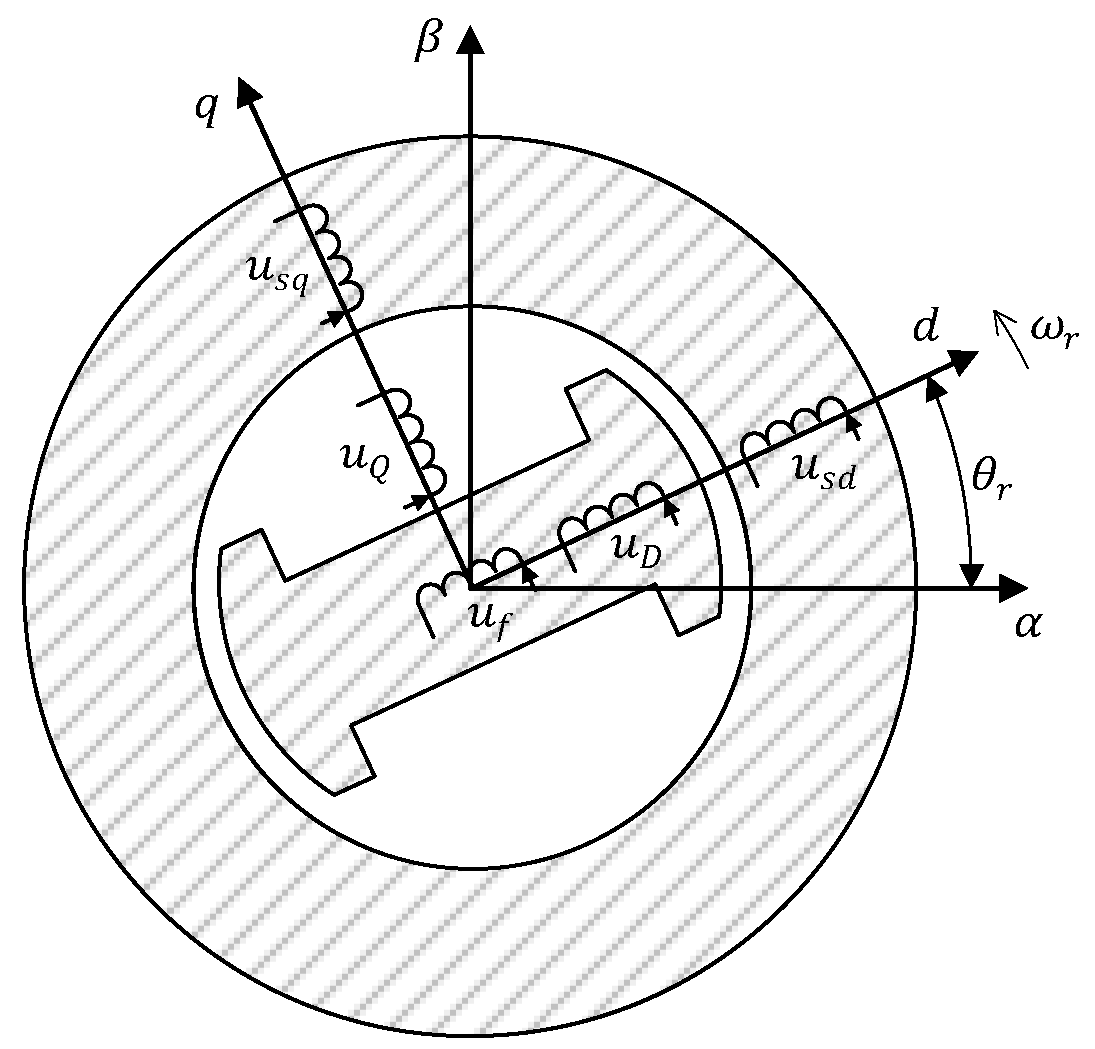
2. Mathematical Model of Salient Pole Synchronous Machine

The considered salient pole EESM with damper windings in the direct and quadrature axis in the rotor reference frame is presented in Figure 1.
The mathematical model of the synchronous machine under investigation can be described via voltage and flux equations. Voltage equations in direct and quadrature axis of such a model of synchronous machine are given as follows [2,3]:
u s d   =   R s i s d   +   d ψ s d d t     ω r ψ s q , u s q   =   R s i s q   +   d ψ s q d t   +   ω r ψ s d , u f   =   R f i f   +   d ψ f d t , u D   =   R D i D   +   d ψ D d t   =   0 , u Q   =   R Q i Q   +   d ψ Q d t   =   0 ,
where i , ψ and R denote the current, flux and winding resistance, respectively. Subscripts s d , s q , f , D and Q denote the stator direct axis component, stator quadrature axis component, excitation, damper winding in direct axis and damper winding in the quadrature axis, respectively. R s is the stator winding resistance and ω r is the electrical rotor speed. The machine flux can be described as a function of currents as follows:
ψ s d   =   L s σ i s d   +   ψ m d   =   L s σ i s d   +   L m d i m d , i m q i m d , ψ s q   =   L s σ i s q   +   ψ m q   =   L s σ i s q   +   L m q i m d , i m q i m q , ψ f   =   L f σ i f   +   ψ m d   =   L f σ i f   +   L m d i m d , i m q i m d , ψ D   =   L D σ i D   +   ψ m d = L D σ i D   +   L m d i m d , i m q i m d , ψ Q   =   L Q σ i Q   +   ψ m q   =   L Q σ i Q   +   L m q i m d , i m q i m q ,
where L and i represent the inductance and current, respectively. Subscripts s σ , f σ , D σ , Q d , m d and m q denote the stator leakage, excitation leakage, damper winding in direct axis leakage, damper winding in quadrature leakage, magnetizing in the direct axis and magnetizing in the quadrature axis, respectively. As stated in Equation (2), magnetizing inductances in the direct and quadrature axis due to saturation and cross-coupling effects can be described as a function of total magnetizing currents in both axis which are defined as follows:
i m d   =   i s d   +   i f   +   i D , i m q   =   i s q   +   i Q .

3. Hybrid Model

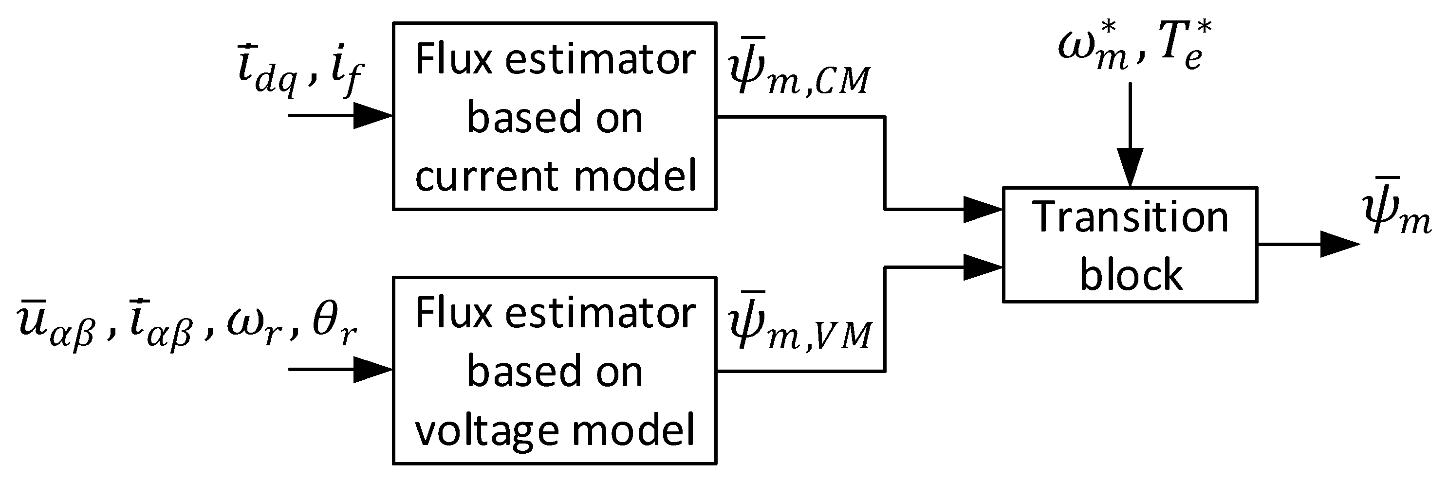
3.1. Overview of the Proposed Flux Hybrid Model

As stated in the Introduction, the goal of this paper is to develop a reliable flux estimator for salient pole EESM applicable in industry applications using cycloconverter drives. A flux estimator for such applications should handle operations where high voltage and current ripple are present during the normal operation of the drive. Furthermore, it should handle the problems related to the discontinuous current in such a drive [21,22]. Moreover, the developed flux estimator should use basic machine parameters that are commonly available in industrial applications, e.g., stator resistance and leakage inductance and direct axis saturation characteristics.
The proposed flux estimator consists primarily of three main parts: flux estimators based on the current and voltage models of the machine and a transition block to manage the transition between the estimators. A basic block diagram of the proposed flux estimator is shown in Figure 2, where dashes above the variables denote vectors and the asterisks, reference values.
As shown on Figure 2, the transition block manages the smooth transition between the estimators based on speed ( ω m * ) and torque ( T e * ) reference signals. The speed reference is used as in a classical approach, where a current model is primarily used at low speeds and a voltage model at medium and high machine speeds. In addition to the speed reference, authors propose that in applications with cycloconverters the torque reference should also be used to manage the smooth transition between the estimators. The basic idea for torque reference usage is to increase the dynamics of the drive at low-speed range, i.e., to increase the influence of the voltage model at low speed and high torque region. The reason for such an approach lies in the fact that the maximum output frequency of the cycloconverter without circulating current is around one third of the input line frequency [21,22], therefore the cycloconverter drive is primary used in the low speed-range.

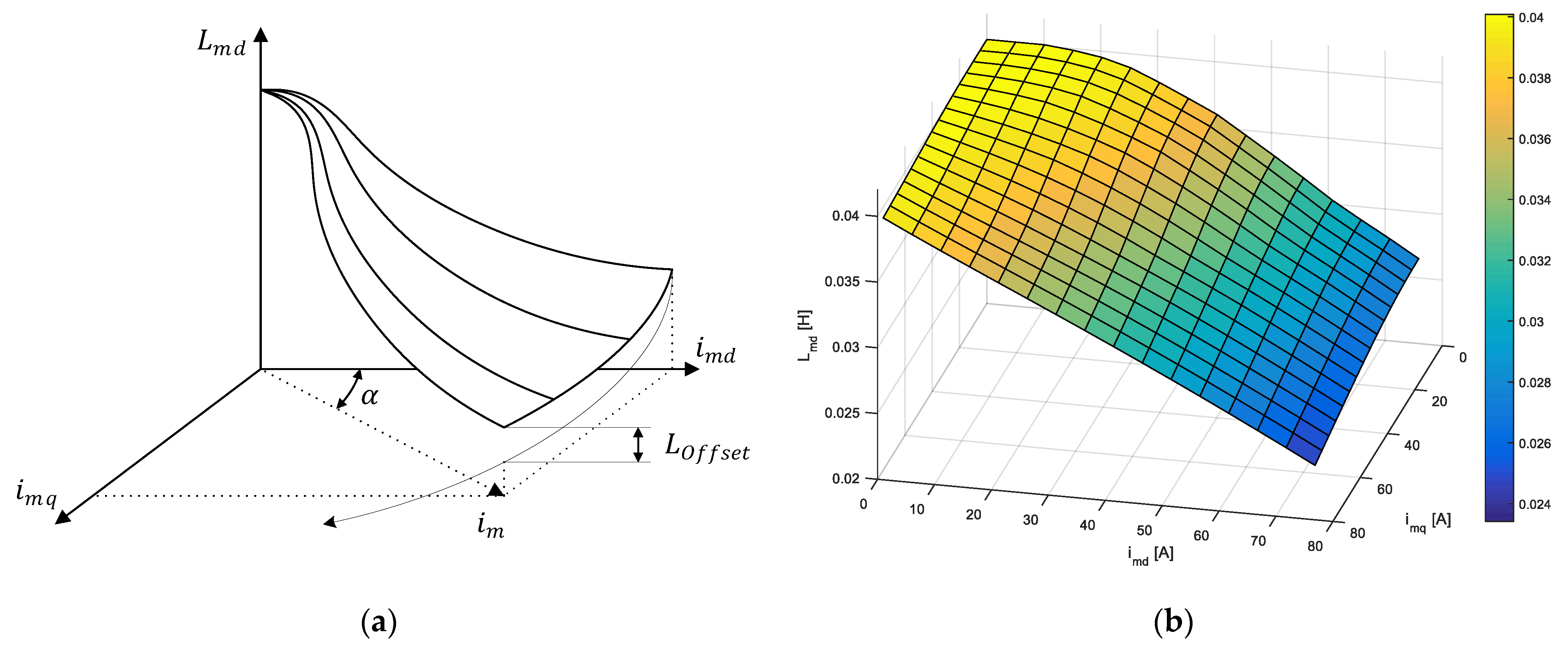
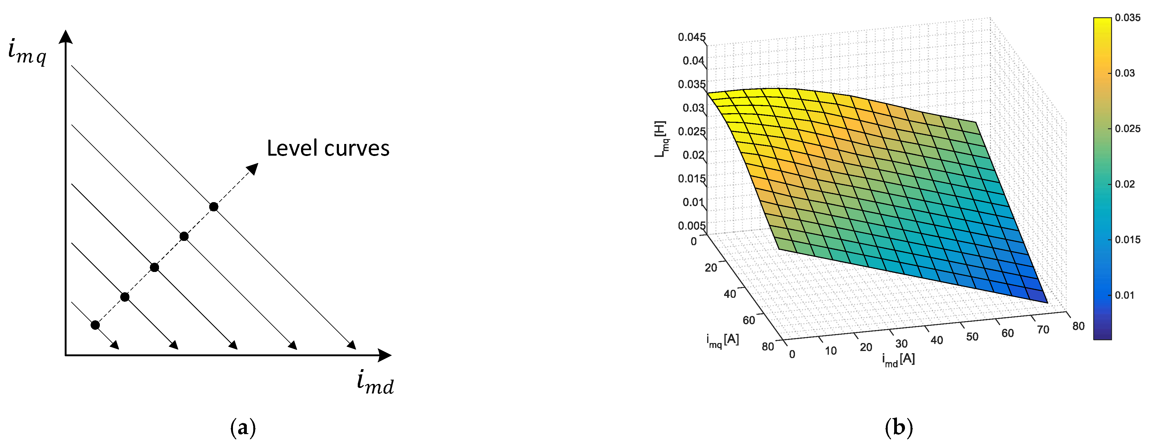
3.2. Flux Estimator Based on Current Model of the Machine

The flux estimator based on the current model is used to determine the nonlinear relationship between the machine current and the flux, i.e., to determine the machine inductances in the direct and quadrature axes. As shown in Equation (2), due to saturation and cross coupling effects between the direct and quadrature axes in the machine, the inductances L m d i m d , i m q and L m q i m d , i m q are described as two variable functions of the magnetizing currents in both axes [2].
The starting point for determining these inductance functions is to define them when excitation is only present in one of the axes. This can be defined as follows:
L m d i m d ,   i m q   =   0   =   L m d i m d , L m q i m d   =   0 ,   i m q   =   L m q i m q ,
where L m d i m d and L m q i m q are the open circuit saturation curves when excitation is only present in the direct or quadrature axis, respectively. As proposed in [12], the inductance function in direct axis can be generated by projecting the direct axis open circuit saturation curve in the direction of the magnetizing current space vector and simultaneously adding the saliency offset to the projected curve, where the amplitude of the magnetizing current space vector is defined as:
i m   =   i m d 2   +   i m q 2 ,
and the saliency offset as:
L O f f s e t   =   L m q u L m d u   ·   2   ·   α π 2   ·   L m d u     L m d i m ,
where L m d u and L m q u are unsaturated magnetizing inductances in the direct and the quadrature axis, respectively. α is an angle of the magnetizing current space vector. Figure 3a shows the basic idea behind the projection of the open circuit saturation curve, and Figure 3b shows inductance function in the direct axis of the considered synchronous machine (Appendix A).
Opposite to the method for the inductance function determination in the direct axis, the method for determining the inductance function in quadrature axis is somewhat different. The open circuit saturation curve in quadrature axis is not usually available in industry applications. For this reason, the open circuit saturation curve in quadrature axis can be determined by assuming the same degree of the saturation in both axes as follows [4]:
L m q i m q   =   L m q u L m d u L m d i m q .
The inductance function in quadrature axis can be determined as in [12], where the author proposed that the inductance function in quadrature axis for a certain i m d , i m q plane (level curves), has a constant value.
These level curves are represented with straight lines on the Figure 4a, whose origins is open circuit saturation curve in quadrature axis defined with Equation (7). Figure 4b shows generated inductance function in the quadrature axis of the considered synchronous machine.

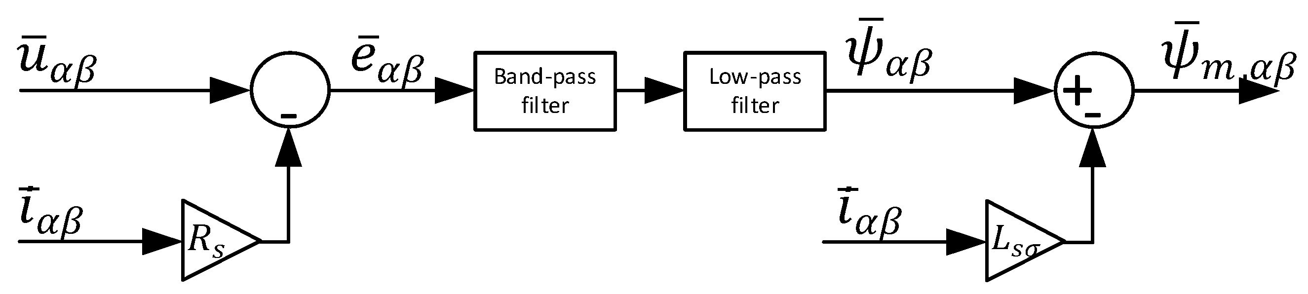
3.3. Flux Estimator Based on Voltage Model of the Machine

The flux estimator based on the voltage model of the machine depends on the integration of the back EMF in stationary reference frame ( α β ). This back EMF of the synchronous machine can be expressed as the difference between the stator voltage and the voltage drop on the stator resistance. Furthermore, the magnetizing flux of the machine is then calculated by integrating the back EMF and subtracting the stator leakage flux from it. Mathematically, this can be expressed as follows [4,14,23]:
ψ ¯ m , α β   =   u   ¯ α β     R s   i ¯ α β d t     L s σ   i ¯ α β ,
where u   ¯ α β , i   ¯ α β and ψ ¯ m , α β   are the vectors of the voltage, current and magnetizing flux in stationary reference frame, respectively.
As stated in [5,6], integrators are prone to drift problems due to error measurements and uncertainties related to the integrator initial conditions. Combining these problems with the high voltage and current ripple in cycloconverter drives applications, it is clear that the design of the flux estimator based on the voltage model of the machine for cycloconverter drives is a complex task. To overcome these problems, the authors propose the flux estimator based on the LPF and the band pass filter (BPF) with variable resonant (center) frequency. Structure of the proposed flux estimator is presented in Figure 5.
As Figure 5 shows, the calculated machine back EMF is filtered with BPF whose resonant frequency is equal to the rotor electrical speed ω r . In this particular case, BPF removes all the ripple from the calculated back EMF without changing the signal (back EMF) amplitude or the phase. The transfer function of the BPF used in the flux estimator is as follows:
G B P F s   =   ω Q s s 2   +   ω Q s   +   ω 2 ,
where ω is the center frequency and the Q is the quality factor of the filter.

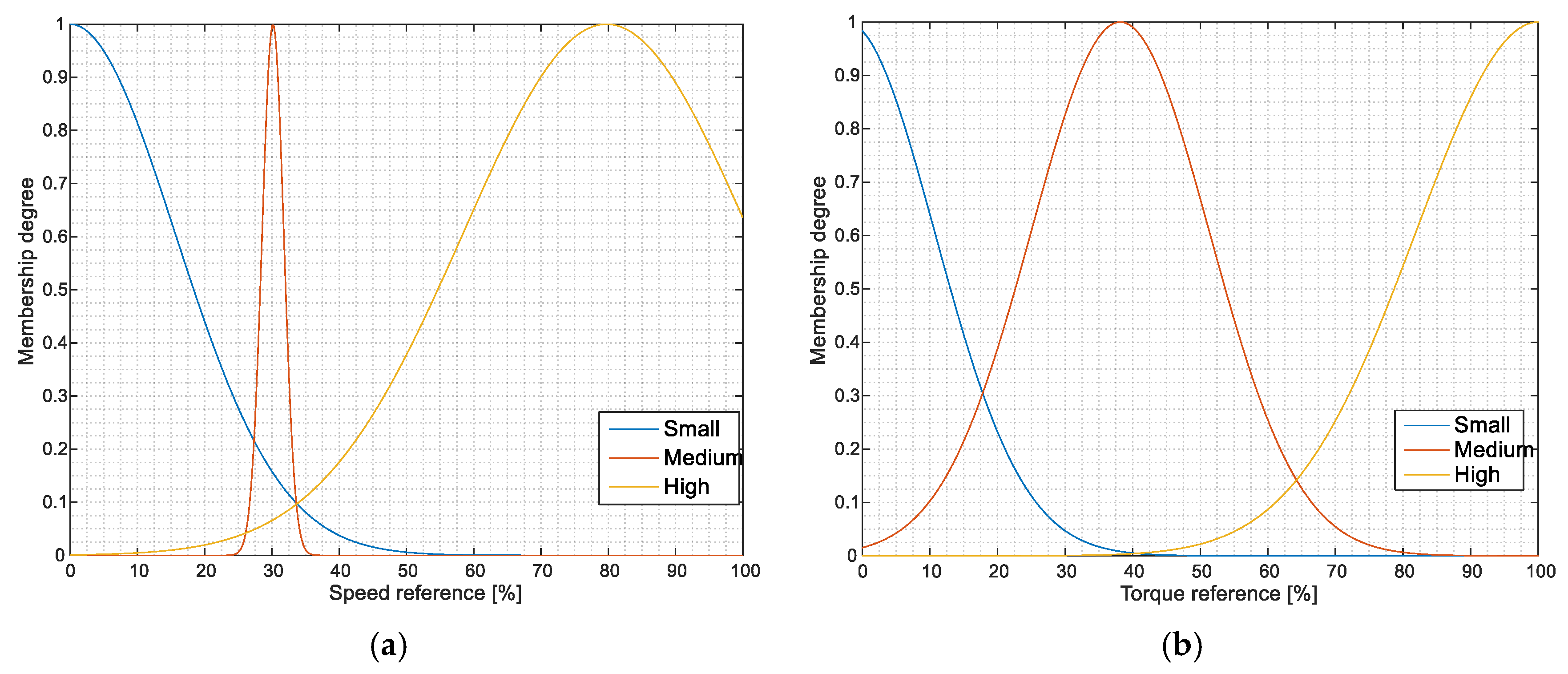
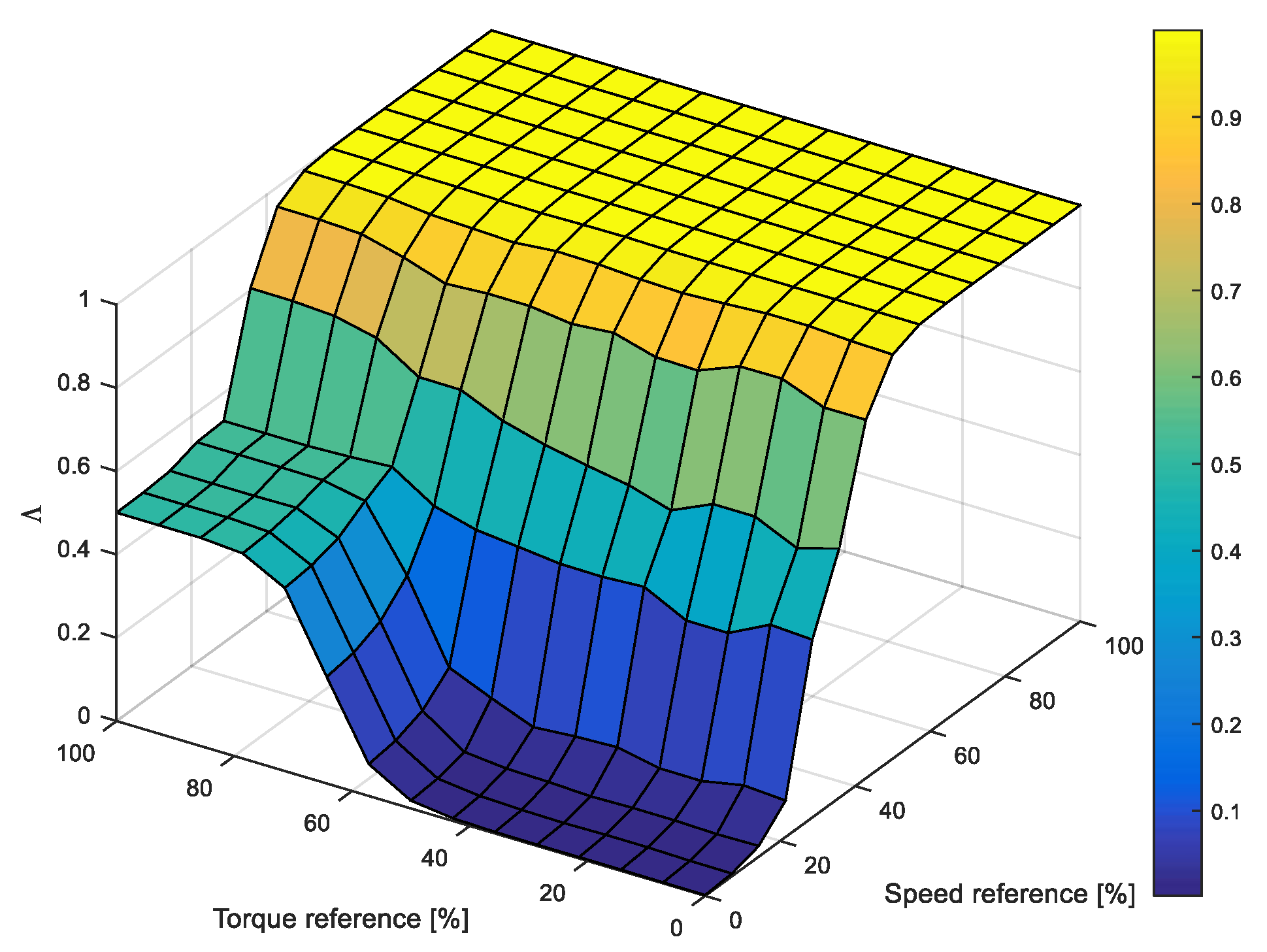
3.4. Design of the Fuzzy Transition between the Flux Estimator Based on Current and Voltage Model

The transition between the flux estimators presented in Section 3.2 and Section 3.3 needs to be as smooth as possible, e.g., without flux or torque step changes, otherwise the stability of the system could be compromised. To ensure this smooth transition between the estimators, a transition function is used. This function is defined as follows:
ψ ¯ m   =   1     Λ ψ ¯ m , C M   +   Λ ψ ¯ m , V M ,
where ψ ¯ m is a vector of the magnetizing flux used by the control algorithm. ψ ¯ m , C M and ψ ¯ m , V M are the vectors of magnetizing flux obtained by the flux estimators based on current and voltage model, respectively. Λ is the transition coefficient used for the controlling the rate of the transition between the current and voltage based estimator. This coefficient lies in the range of [0, 1], and it is obtained by fuzzy logic set of rules.
The principle of the fuzzy logic set of rules to manage the transition between the current and voltage-based estimator is based on Sugeno Fuzzy Inference Systems. As stated, in this approach we have two inputs (speed and torque reference) whose membership functions are presented in Figure 6.
As shown on Figure 6, all membership functions of the speed and torque reference are based on the Gaussian membership functions. These functions are defined to cover the whole range of input variables and to enable the smooth transition between the estimators as it is stated before. Output from the fuzzy logic transition block represents the transition coefficient Λ , which is calculated based on the fuzzy logic set of rules presented in the Table 1.
A total of nine rules is generated from Table 1. Some of the fuzzy logic set of rules are defined as:
  • IF (Speed is Small) AND (Torque is Small) THEN Λ   =   0
  • IF (Speed is High) AND (Torque is High) THEN Λ   =   1
Figure 7 shows the output of the fuzzy logic transition block. The presented output on the Figure 7 clearly shows that in the low speed/low torque region the flux estimator based on the current model has the dominant influence on the control system. As the speed increases (above 20% of the rated speed), the influence of the estimator based on current model starts to decrease and the estimator based on the voltage model starts to be dominant in the output. Furthermore, the transition also enables the flux estimator based on voltage model to contribute to the flux estimation at low speeds if the machine torque increases above 40% of the rated torque. This contribution increases the accuracy of the estimated flux (increases the system dynamic response) at low machine speeds which is significant in cycloconverter drives without a circulating current whose maximum output frequency is around 1/3 of the input line frequency.

4. Experimental Verification of the Proposed Flux Estimator
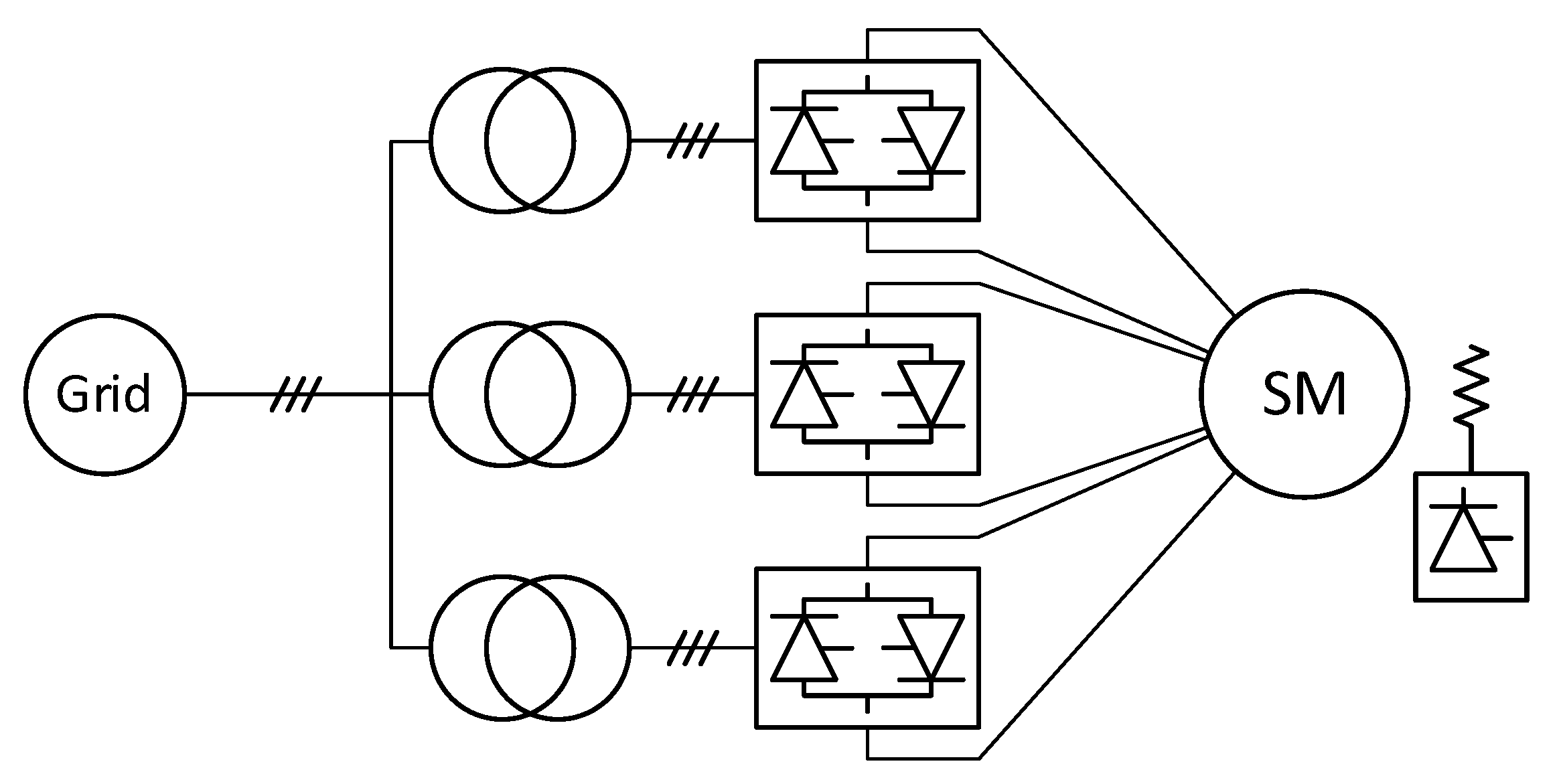
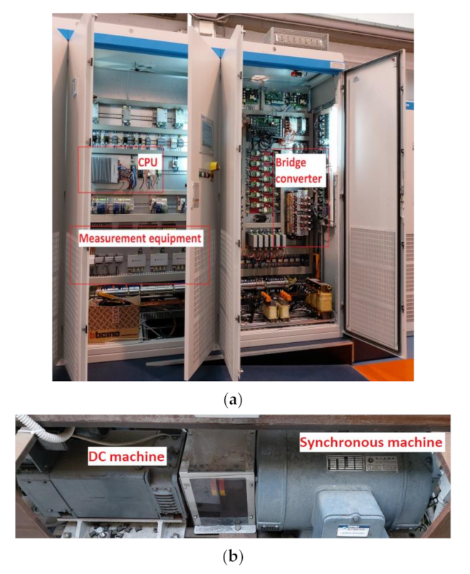
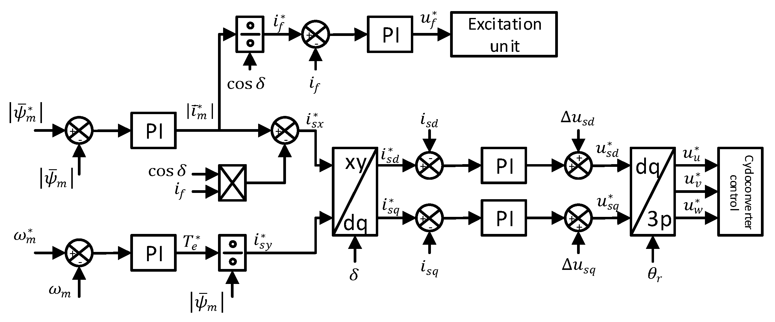
4.1. System Setup

The proposed flux estimator was experimentally verified on a salient pole EESM fed by the cycloconverter. The cycloconverter consists of three four quadrant six pulse bridge converters operating without a circulating current, where each bridge powers one of the machine phases. Each bridge input is connected to the separate transformer whose primary sides are connected to the power grid of 400 V and 50 Hz. The synchronous machine is mechanically coupled to a direct current (dc) machine operated in the torque control mode which enables the generation of the load torque for the synchronous machine. Figure 8 presents a block diagram of the cycloconverter drive used for the experimental verification of the proposed flux estimator.
Figure 9a presents two cabinets of the cycloconverter drive unit, where the left cabinet is the control part which consist of the central processing unit (CPU) and the measurement equipment. The cabinet to the right is the power part, i.e., the bridge converter for one of the machine phases. Figure 9b represents the mechanically coupled salient pole EESM and the dc machine used during the experimental verifications of the proposed flux estimator.
The control diagram of the FOC, or more precisely, the magnetizing flux-oriented control of the salient pole EESM is presented in Figure 10. The control diagram consists of inner currents loops, and outer flux and speed loop. The output of the speed loop is the torque reference, which is used with a speed reference to manage the transition between the proposed flux estimators. Furthermore, based on torque reference signal the reference value of the stator current in y axis ( i s y * ) is calculated. The magnetizing current reference is the output of the flux loop on which basis the stator magnetizing current reference ( i s x * ) and the excitation current reference ( i f * ) are calculated. Inner current loops based on current references and feedbacks regulate the machine stator and excitation current. In Figure 10, δ , Δ u s d and Δ u s q represent the load angle and decoupling signals in the direct and quadrature axis, respectively [2,3]. This control is implemented in the CPU of the cycloconverter drive and it is tuned based on the experience of the authors to achieve a good dynamic response of the system.

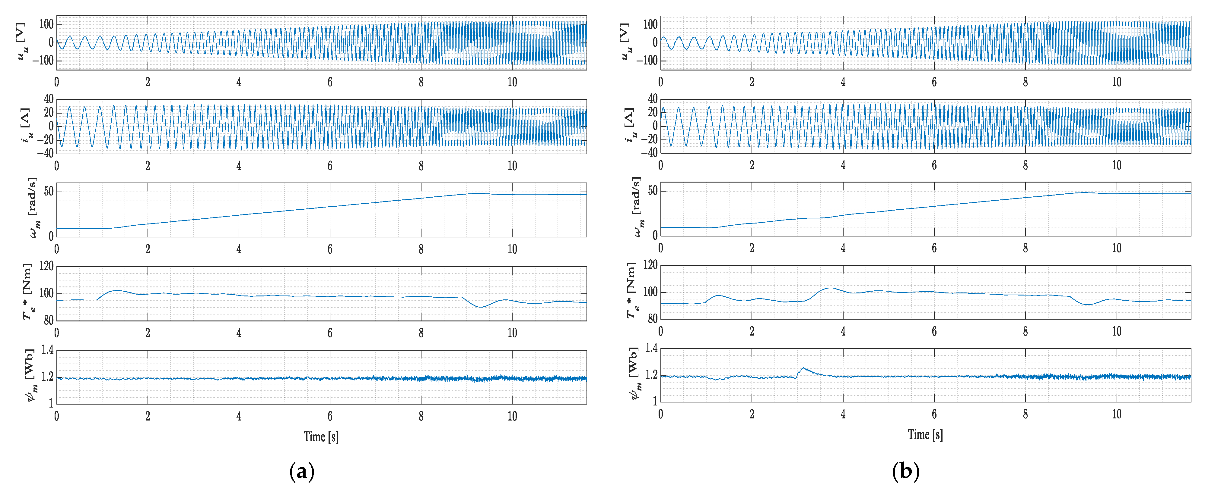
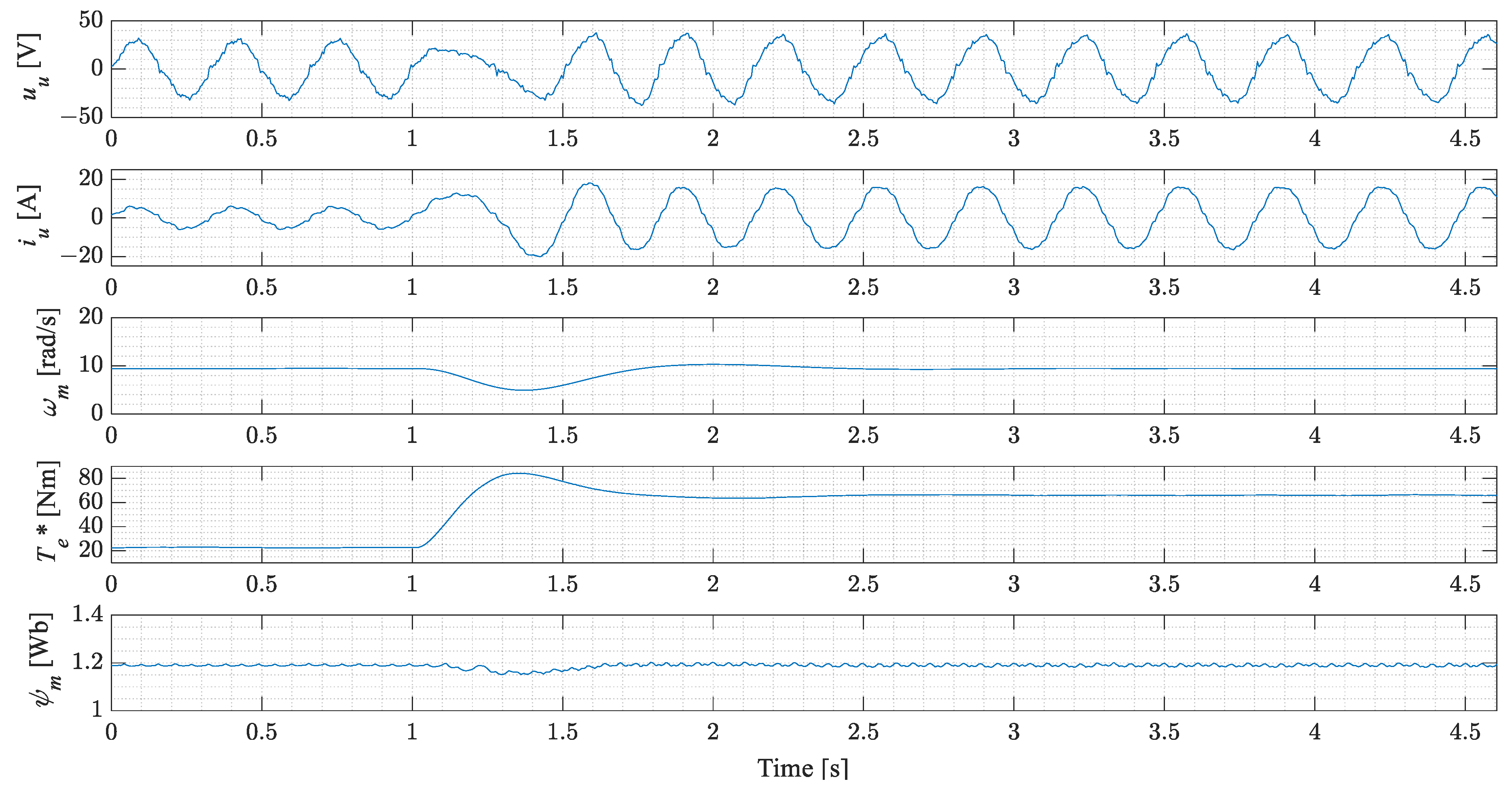
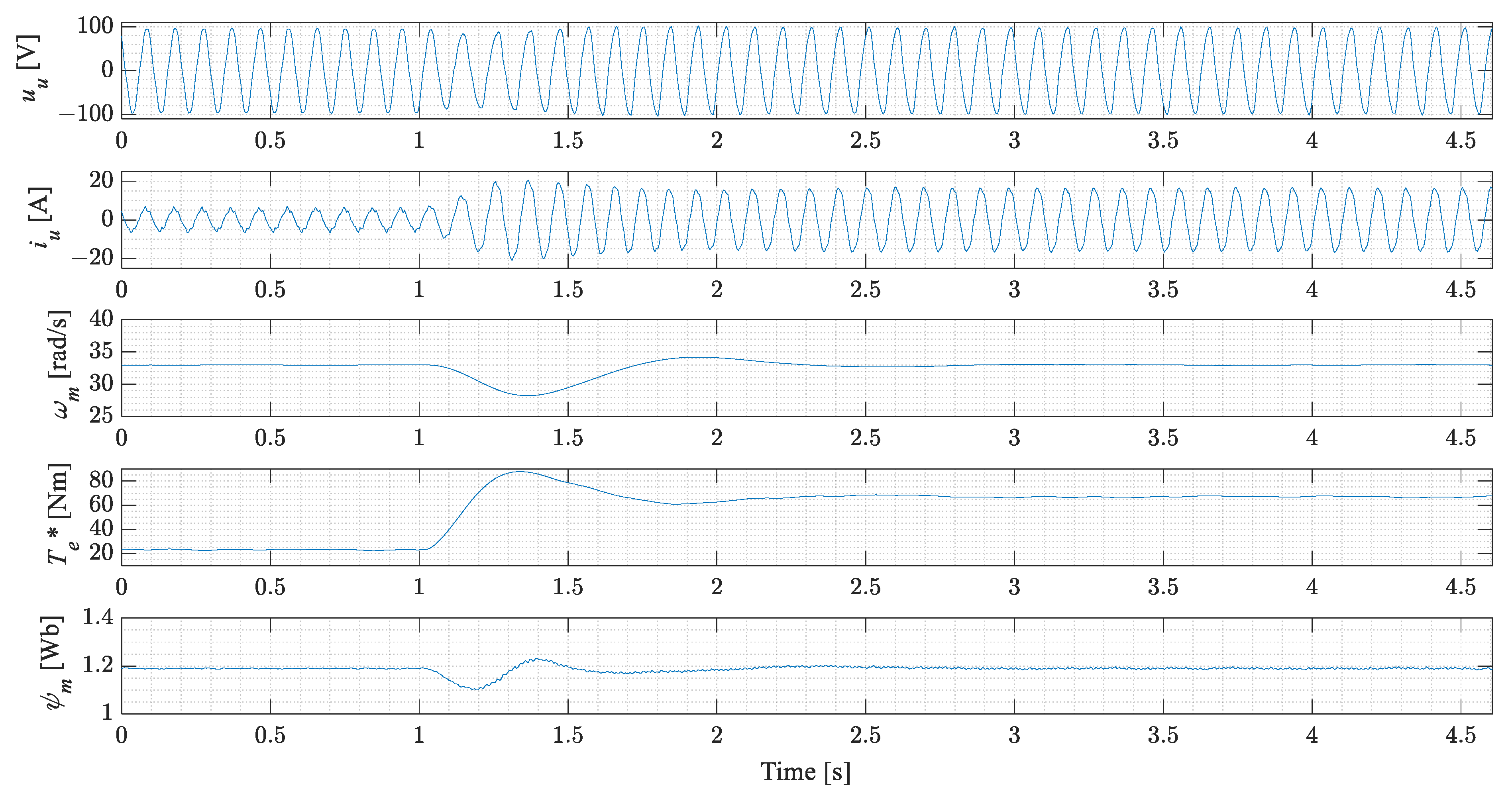
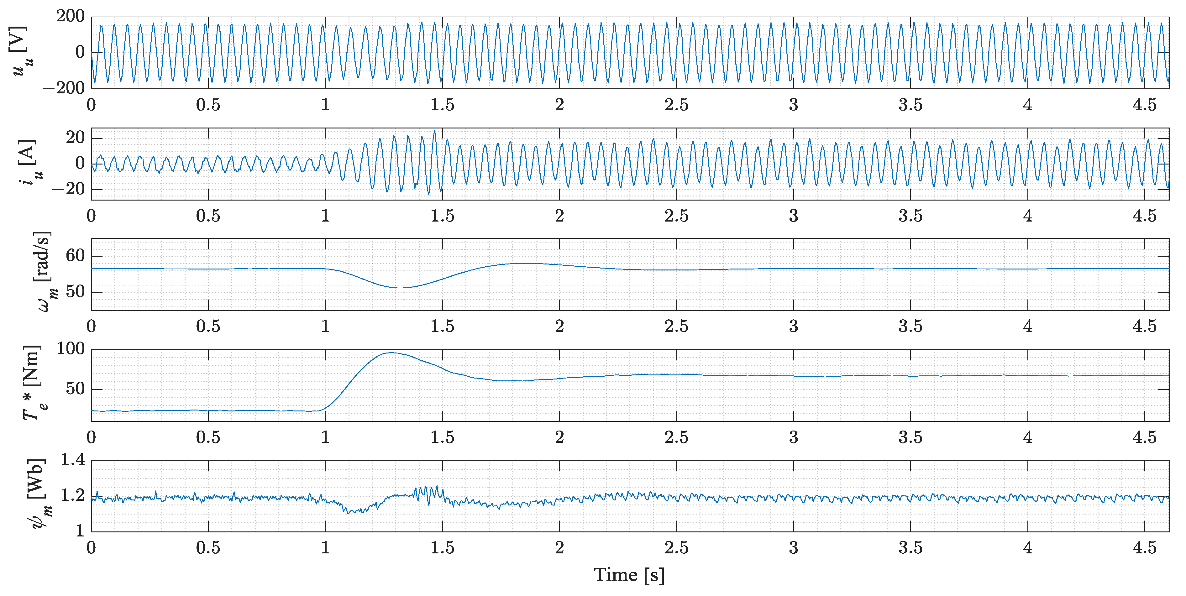
4.2. Experimental Results and Analysis

Experimental verification of the proposed flux estimator was carried out in two phases. In the first phase, the stability of the proposed flux estimator was tested during a variable speed situation (machine acceleration). The second phase consists of the evaluation of the proposed estimator during a load torque change.
As stated, the first experiment involves machine acceleration under a constant load torque. The experiment starts with synchronous machine running at 10% of the rated speed with 50% of the rated load torque. Then, at some point the machine starts to accelerate during which time the load torque remains at 50%. The experiment ends with machine reaching 50% of the rated speed which corresponds to a stator frequency of 15 Hz. This experiment was done for two cases of the flux estimator, the first one is with proposed flux estimator with a fuzzy logic set of rules for the transition between the flux estimators, and second case is when the transition between the estimator is done with the switch (when a certain speed is reached, control is transferred to the flux estimator based on the voltage model of the machine). For each experiment a waveform of the measured voltage and current (average values), speed, magnetizing flux and torque reference isgiven.
Figure 11a presents the waveforms acquired during the experiment with the transition between the estimators based on the proposed fuzzy set of rules. The experiment starts at t     1   s , when the machine starts to accelerate. During this time (acceleration), the flux estimator transfers the control from the estimator based on the current model to the estimator based on the voltage model. This transition between the estimators, as clearly shown on the waveforms, occurs without any torque or flux steps changes or oscillatory transitions. Figure 11b shows the waveforms during the acceleration of the machine with a classical transition between the estimators. The experiment also starts with acceleration of the machine at the t     1   s , when machine torque starts to increase. As shown in the presented waveforms, at t     3   s when the transition occurs, a disturbance is present in the system. The torque reference increases even more, and there is a disturbance in the estimated flux. Comparing the measured speeds for both experiments, it is clear that the acceleration of the machine when the flux estimator with fuzzy logic set of rules transition is enabled has the smoother acceleration to the setpoint.
The second experiment evaluates the proposed flux estimator based on the dynamic response of the system during load torque changes. This experiment starts by running the machine at a constant speed and then the load torque is suddenly increased. Experiments were conducted at 10%, 35% and 60% of the rated machine speed which correspond to the stator frequency of 3, 10.5 and 18 Hz, respectively. The experimental results obtained during these load torque changes are shown in Figure 12, Figure 13 and Figure 14.
As it can be seen from the experimental results (Figure 12, Figure 13 and Figure 14), the load torque changes at t     1 s . At that point, the torque reference starts to increase to compensate the speed drop. It is clearly noticeable in the result that the response of the torque is smooth without any additional oscillations caused by the proposed flux estimator. During that time, a disturbance is also present in the flux, but it is quickly compensated by the flux controller.

4.3. Analyisis of the Experimental Results

Section 4.2 presented the experimental results of the proposed flux estimator for the salient pole EESM driven by the cycloconverter drive. The conducted experiments are divided into two main groups: speed reference change and load torque change. In the first experiment, the fuzzy logic transition between the estimators was tested. As presented in Figure 11a, during the machine acceleration the transition between the estimators (from the current to the voltage-based estimator) was smooth (no torque or flux steps) without additional oscillations which can cause instabilities in the control system. Compared to the experimental results obtained by the classical transition between the flux estimators (Figure 11b), the proposed transition based on fuzzy logic set of rules clearly shows the advantages of such an approach.
In the second experiment (Figure 12, Figure 13 and Figure 14), the dynamic torque response of the cycloconverter drive was tested at 10%, 35% and 50% of the rated machine speed. In all three cases, the cycloconverter drive system remained stable after a load torque change. The accuracy of the proposed flux estimator can be determined by comparing the voltage amplitudes just prior and after a load torque change (when a new steady state is reached). This comparison clearly shows that the voltage amplitude (just prior to and after a load torque change) does not change, which is a clear sign of high accuracy of the estimated flux.

5. Conclusions

In this paper, a flux estimator for the salient pole EESM is proposed. The proposed flux estimator consists of estimators based on current and voltage models of the machine with a fuzzy logic set of rules to manage the transition between them. The estimator based on the current model incorporates saturation and cross-coupling effects in both axis and it is suitable for industry applications with cycloconverter drives where a limited amount of machine data is available. The flux estimator based on the voltage model is based on the combination of a low-pass and a band-pass filter for integrating/filtering the back EMF of the machine to reduce the high ripple in voltage and current generated by the cycloconverter drive. The transition between the estimators is managed based on speed and torque references and a fuzzy set of rules. The proposed flux estimator was verified on an experimental setup consisting of a salient pole EESM driven by the cycloconverter. In the first experiment the salient pole EESM was accelerated under a constant load. This experiment was carried out for two cases of the flux estimators, the first one is when the transition between the estimators is carried out with proposed fuzzy logic-based transition and the second one is with a classical transition. The presented results clearly show that with fuzzy logic-based transition the acceleration of the machine is carried out without torque and flux steps, compared to the classical transition where torque and flux disturbances are present. The second experiment tested the stability and dynamic response of the cycloconverter drive during a load torque change when the machine flux is estimated with the proposed estimator. The obtained results clearly show that system remains stable after a load torque is applied, e.g., the system quickly enters a new steady state without additional oscillations. Furthermore, the obtained results show that machine voltage prior and after a load torque change remain the same (amplitude) which is a clear sign of the high accuracy of the proposed estimator.

Author Contributions

Conceptualization, D.C.; Methodology, D.C.; Software, D.C.; Validation, D.C. and N.T.; Formal analysis D.C. and N.T.; Investigation, D.C. and N.T.; Resources, D.C. and N.T.; Data Curation, D.C. and N.T.; writing—original draft, D.C.; writing—review and editing, D.C., N.T. and N.B.; Visualization, D.C. and S.B.; Supervision, N.T. and N.B.; Project administration, N.B. and S.B.; Funding acquisition, N.B. and S.B. All authors have read and agreed to the published version of the manuscript.

Funding

This research was funded in part by the University of Rijeka (Croatia) under the project uniri-tehnic-18-74 1207 and University of Rijeka (Croatia), Faculty of Engineering under the project Advanced Control Structures For Electrical Drives. This work has been partly supported by the COMET-K2 Center of the Linz Center of Mechatronics (LCM) funded by the Austrian federal government and the federal state of Upper Austria.

Institutional Review Board Statement

Not applicable.

Informed Consent Statement

Not applicable.

Data Availability Statement

Not applicable.

Acknowledgments

The authors would like to thank the Danieli Automation SpA (Italy) company for the support.

Conflicts of Interest

The authors declare no conflict of interest.

Appendix A

Table A1. Salient pole synchronous machine nameplate data and parameters.
ParameterSymbolValueUnit
Rated power P n 18.5kW
Rated stator voltage U n 400V
Rated stator current I n 29.2A
Rated excitation voltage U n , f 65V
Rated excitation current I n , f 11A
Rated stator frequency f n 30Hz
Number of pole pairs p p 2-
Stator resistance R s 0.244
Stator leakage inductance L s σ 0.0076H
Unsaturated magnetizing inductance in the direct axis L m d u 0.04H
Unsaturated magnetizing inductance in the quadrature axis L m q u 0.035H
Damping winding resistance in the direct axis R D 1.08
Damping winding resistance in the quadrature axis R Q 1.26
Damper winding leakage inductance in the direct axis L D σ 0.0048H
Damper winding leakage inductance in the quadrature axis L Q σ 0.0058H
Figure A1. Open circuit saturation curve in the direct axis.
Machines 09 00279 g0a1

References

  1. Leonhard, W. Control of Electrical Drives, 3rd ed.; Springer: Berlin/Heidelberg, Germany, 2001. [Google Scholar]
  2. Vas, P. Vector Control of AC Machines; Oxford University Press: New York, NY, USA, 1990. [Google Scholar]
  3. Vas, P. Sensorless Vector and Direct Torque Control; Oxford University Press: New York, NY, USA, 1998. [Google Scholar]
  4. Han, Y.; Wu, X.; He, G.; Hu, Y.; Ni, K. Nonlinear Magnetic Field Vector Control with Dynamic-Variant Parameters for High-Power Electrically Excited Synchronous Motor. IEEE Trans. Power Electron. 2020, 35, 11053–11063. [Google Scholar] [CrossRef]
  5. Zhou, Y.; Long, S. Sensorless Direct Torque Control for Electrically Excited Synchronous Motor Based on Injecting High-Frequency Ripple Current into Rotor Winding. IEEE Trans. Energy Convers. 2015, 30, 246–253. [Google Scholar] [CrossRef]
  6. Koteich, M. Flux estimation algorithms for electric drives: A comparative study. In Proceedings of the 3rd International Conference on Renewable Energies for Developing Countries (REDEC), Zouk Mosbeh, Lebanon, 13–15 July 2016. [Google Scholar]
  7. Pyrhönen, J.; Hrabovcová, V.; Semken, R.S. Electrical Machine Drives Control, 1st ed.; John Wiley & Sons: Chichester, UK, 2016. [Google Scholar]
  8. Levi, E. Saturation modelling in d-q axis models of salient pole synchronous machines. IEEE Trans. Energy Convers. 1999, 14, 44–50. [Google Scholar] [CrossRef]
  9. Levi, E.; Levi, V.A. Impact of dynamic cross-saturation on accuracy of saturated synchronous machine models. IEEE Trans. Energy Convers. 2000, 15, 224–230. [Google Scholar] [CrossRef]
  10. Jeong, I.; Gu, B.G.; Kim, J.; Nam, K.; Kim, Y. Inductance Estimation of Electrically Excited Synchronous Motor via Polynomial Approximations by Least Square Method. IEEE Trans. Ind. Appl. 2015, 51, 1526–1537. [Google Scholar] [CrossRef]
  11. Kar, N.C.; El-Serafi, A.M. Measurement of the saturation characteristic in the quadrature axis of synchronous machines. IEEE Trans. Energy Convers. 2006, 21, 690–698. [Google Scholar] [CrossRef]
  12. Kaukonen, J. Salient Pole Synchronous Machine Modelling in an Industrial Direct Torque Controlled Drive Application. Ph.D. Thesis, Lappeenranta University of Technology, Lappeenranta, Finland, 26 March 1999. [Google Scholar]
  13. Hu, J.; Wu, B. New integration algorithms for estimating motor flux over a wide speed range. IEEE Trans. Power Electron. 1998, 13, 969–977. [Google Scholar]
  14. Wang, D.; Lu, K.; Rasmussen, P.O. Improved Closed-Loop Flux Observer Based Sensorless Control Againts System Oscillation for Synchronous Reluctance Machine Drives. IEEE Trans. Power Electron. 2019, 34, 4593–4602. [Google Scholar] [CrossRef] [Green Version]
  15. Stojić, D.; Milinković, M.; Veinović, S.; Klasnić, I. Improved Stator Flux Estimator for Speed Sensorless Induction Motor Drives. IEEE Trans. Power Electron. 2015, 30, 2363–2371. [Google Scholar] [CrossRef]
  16. Golestan, S.; Guerrero, J.M.; Gharehpetian, G.B. Five Approaches to Deal with Problem of DC Offset in Phase-Locked Loop Algorithms: Design Considerations and Performance Evaluations. IEEE Trans. Power Electron. 2016, 31, 648–661. [Google Scholar] [CrossRef] [Green Version]
  17. Sevilmis, F.; Karaca, H. Performance Analysis of Dual Second Order Generalized Integrator Phase Locked Loop for Grid Interactive Inverter. In Proceedings of the 6th International Conference on Advanced Technology & Sciences (ICAT’Riga), Riga, Latvia, 12–15 September 2017. [Google Scholar]
  18. Li, Q.; Jiang, D.; Zhang, Y. Analysis and Calculation of Current Ripple Considering Inductance Saturation and Its Application to Variable Switching Frequency PWM. IEEE Trans. Power Electron. 2019, 34, 12262–12273. [Google Scholar] [CrossRef]
  19. Tang, Q.; Chen, D.; He, X. Integration of Improved Flux Linkage Observer and I-f Starting Method for Wide-Speed-Range Sensorless SPMSM Drives. IEEE Trans. Power Electron. 2020, 35, 8374–8383. [Google Scholar] [CrossRef]
  20. Aliaskari, A.; Davari, S.A. A new closed-loop voltage model flux observer for sensorless DTC method. In Proceedings of the 8th Power Electronics, Drive Systems & Technologies Conference (PEDSTC), Mashhad, Iran, 14–16 February 2017. [Google Scholar]
  21. Pelly, B.R. Thyristor Phase-Controlled Converters and Cycloconverters; John Wiley & Sons: New York, NY, USA, 1971. [Google Scholar]
  22. Lei, M.; Li, C.; Duan, W.; Zhang, Y.; Li, F. Research on the control methods of large-power cyclo-converter under the discontinuous conduction mode. In Proceedings of the IEEE 6th International Power Electronics and Motion Control Conference, Wuhan, China, 17–20 May 2009. [Google Scholar]
  23. Sangsefidi, Y.; Ziaeinejad, S.; Mehrizi-Sani, A. Sensorless Speed Control of Synchronous Motors: Analysis and Mitigation of Stator Resistance Error. IEEE Trans. Energy Convers. 2016, 31, 540–548. [Google Scholar] [CrossRef]
Figure 1. Salient pole synchronous machine model in the rotor reference frame.
Machines 09 00279 g001
Figure 2. Block diagram of the proposed flux estimator for salient pole synchronous machine.
Machines 09 00279 g002
Figure 3. (a) Generation of the inductance function in the direct axis according to [12]; (b) Inductance function in the direct axis.
Machines 09 00279 g003
Figure 4. (a) Generation of the inductance function in the quadrature axis according to [12]; (b) Generated inductance functions in the quadrature axis.
Machines 09 00279 g004
Figure 5. Block diagram of the flux estimator based on the voltage model of the machine.
Machines 09 00279 g005
Figure 6. (a) Speed reference membership function; (b) Torque reference membership function.
Machines 09 00279 g006
Figure 7. Output of the fuzzy logic transition block.
Machines 09 00279 g007
Figure 8. Block diagram of the cycloconverter drive.
Machines 09 00279 g008
Figure 9. (a) Control and the power part (one phase) of the cycloconverter; (b) Salient pole EESM and DC machine setup.
Machines 09 00279 g009
Figure 10. Control diagram of the magnetizing flux-oriented control for the electrically excited synchronous machine.
Machines 09 00279 g010
Figure 11. Experimental results of the cycloconverter drive during the machine acceleration with (a) Transition based on fuzzy logic set of rules; (b) Classical transition.
Machines 09 00279 g011
Figure 12. Experimental results of the cycloconverter drive during load torque change at 10% of rated machine speed.
Machines 09 00279 g012
Figure 13. Experimental results of the cycloconverter drive during load torque change at 35% of the rated machine speed.
Machines 09 00279 g013
Figure 14. Experimental results of the cycloconverter drive during load torque change at 60% of the rated machine speed.
Machines 09 00279 g014
Table 1. Rule table for the fuzzy logic transition.
Λ . Torque
SmallMediumHigh
SpeedSmall000.5
Medium0.50.50.5
High111
Publisher’s Note: MDPI stays neutral with regard to jurisdictional claims in published maps and institutional affiliations.

