1. Introduction
Due to the advances in computer technology, the computer has been integrated as a tool in the everyday work of engineers. Various software tools have been developed over the last few decades with the aim of supporting the development process of mechanisms. Ever since then, those software tools have played an ever-increasing role in student education as well as in designing mechanisms [
1,
2,
3].
The Institute of Mechanism Theory, Machine Dynamics and Robotics (IGMR) of RWTH Aachen University has a long tradition regarding the analysis, synthesis and design of planar, spherical and spatial mechanisms [
4]. Based on this knowledge and experience, the IGMR started the development of a new mechanism design software called “Mechanism Developer” (MechDev). The software aims to be user-friendly and at the same time provide powerful functionalities that support the user during the mechanism design process [
5]. To allow a continuous integration of new and innovative functionalities within the software, a special focus lies on the software architecture. MechDev is based on the model-view-controller (MVC) architecture, which is especially recommended for user interactive systems [
6]. In combination with a plug-in based structure, new functionalities can easily be added to the software [
5,
7].
Many powerful software tools already exist to support engineers during the mechanism design process. These tools can be divided into three different types: geometric software products, general engineering tools and special mechanism design tools.
Geometric software such as GeoGebra [
8] and Cinderella [
9] can be used to implement graphical methods of mechanism theory dynamically. Therefore, the engineer has to provide deep knowledge in mechanism design [
5]. Furthermore, the named geometric software do not offer the possibility to analyze mechanisms that have to be calculated numerically.
General engineering tools such as computer aided design software (i.e., SolidWorks [
10] or Autodesk Inventor [
11]), as well as multibody dynamics simulation software (i.e., Adams [
12]), can also be used to analyze different kind of mechanism. These powerful tools provide functionalities to consider detailed properties of the mechanism such as friction, physical properties of the material etc. As these programs are developed mainly for the design and analysis of technical systems, they have very limited mechanism synthesis functionalities. In addition, the calculation time of these programs is quite long, since numerical approaches are used. Thus, it is not possible to change kinematical parameters interactively while observing the analysis results in quasi-real-time.
Mechanism design tools are developed specifically for the mechanism design process. Most of them not only provide functionalities to analyze mechanisms but also provide functionalities for the mechanism synthesis. Software products such as SAM [
13] or ASOM [
14] provide functionality for the kinematic and kinetostatic analysis, synthesis and optimization of planar mechanisms based on revolute, prismatic and gear joints, but they do not cover cam mechanisms. Other products such as OPTIMUS MOTUS [
15] or GENESYS [
2,
16] provide powerful methods in mechanism theory and also support cam mechanisms. Both programs focus on the functionalities of mechanism design—the focus is less on the usability of the software. In addition, software products such as OPTIMUS MOTUS are oriented towards industrial applications and thus might have higher license costs [
17]. MechDesigner [
18] is a software product for the design and analysis of cams, motions and mechanisms. Since the focus of the software is on cam mechanisms, the synthesis of linkages can only be realized by a constraint-based sketch-editor. Thus, especially for complex linkages, high levels of knowledge in mechanism theory are required. The software product GIM [
19] is a software for the kinematic analysis of planar and spatial mechanisms and static analysis of planar structures. GIM is licensed under the assumption that it will only be used for educational purposes. Cam mechanisms are not considered.
MechDev is a mechanism design software that focuses on both the usability and the mechanism design functions. In addition to the analysis of mechanisms based on revolute, prismatic, gear and cam joints, powerful methods for the synthesis of such mechanisms are planned. The combination of analytical as well as numerical calculation methods allows the quasi-real-time calculation of mechanisms and hence an interactive mechanism design. In addition, the analysis results can be composed and configured individually for specific tasks. The focus of the software is on academic as well as industrial use. Even if the software design is not yet finished, many mechanism design functionalities are already integrated. This paper is based on [
20] and will sum up the current functionalities of the software MechDev. Then, the functionalities as well as the usage of MechDev will be shown with the help of a special use-case. Since this use-case will include Non-Uniform Rational B-Splines (NURBS), these kinds of spline will be described mathematically. This will include information about how boundary conditions of such splines can be realized.
2. Functionalities of the Mechanism Developer
The previous publications regarding MechDev have focused on the mathematical approach for the analysis of mechanisms based on revolute and prismatic joints [
5,
7] as well as on the calculation of cam mechanisms [
21,
22]. Within this section, the mechanism-based functionalities will be summed up. The focus here is less on the mathematical implementation of the algorithms, but on the application of the individual functionalities. The mechanism design-based functionalities of MechDev are as follows:
Kinematical analysis
Kinetostatical analysis
Synthesis and analysis of cam mechanisms with roller followers or flat-faced followers
Optimization via drag-and-drop
Motion design to model servo drives
Consideration of process forces, spring-damper elements and inertia forces, as well as friction
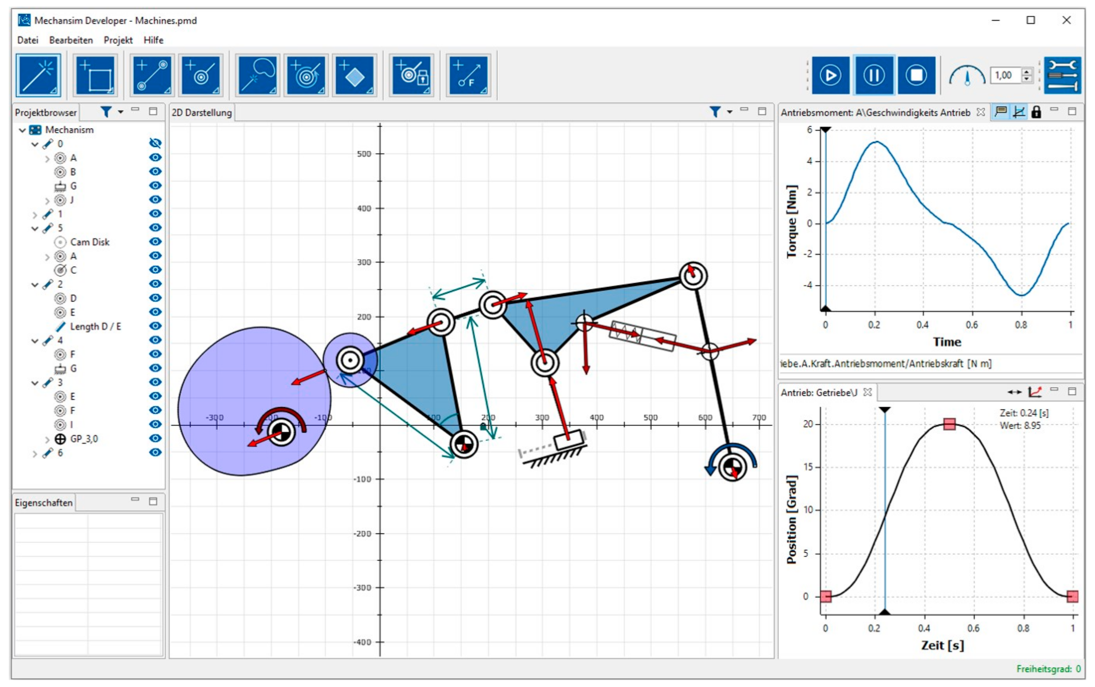
A screenshot of the current software is shown in
Figure 1. This screenshot shows an example of a mechanism with revolute and prismatic joints as well as a cam pair. The revolute joint of the cam is actuated (input motion) and the follower of the cam is part of a six-bar linkage. The rocker on the right executes the output movement.
In order to calculate the shape of the cam disk, an input and an output motion has to be defined. The input motion is visualized by a red curved arrow (left side). The output motion is visualized by a blue curved arrow (right side). To define such motions, MechDev provides a motion design plug-in, which is shown in the bottom right area of
Figure 1. In this plug-in, a motion consists of an arbitrary number of segments. The realized output-motion in
Figure 1 consist of two polynomial segments. In addition to polynomial functions, MechDev currently provides polynomial splines and Non-Uniform Rational B-Splines (NURBS), as well as sinusoidal functions to define motions and proceed the kinematical analysis of mechanisms. This kinematical analysis has been described in [
5,
7]. In order to optimize the calculation time, both analytical and numerical approaches are combined in one powerful approach [
17].
MechDev also provides different elements to define forces acting on the mechanism. As shown in
Figure 1, one possibility is the definition of a spring-damper element. It is defined between two points on two different links. Among others, the relative motion of these links, as well as the damping constant and spring constant, affects the reaction force of the element. Besides these spring-damper elements, it is also possible to define inertia forces, as well as process forces. The results of the kinematical analysis, such as the joint forces and the actuation torque, can be calculated within the kinetostatical analysis. These forces and torques can be visualized and analyzed in diagrams. One example of such a diagram is shown in the upper right area of
Figure 1. This particular diagram shows the actuation torque that has to be provided by the actuator in the revolute joint between the cam disk and the frame. Besides the definition of external forces, MechDev also provides the possibility to consider joint friction of revolute and prismatic joints.
The kinematic dimensions, such as the distance between two elements or the angle between three elements, can be defined in MechDev as well.
Figure 1 shows some examples of such definitions. Among others, the kinematic dimensions of the cam follower are defined by two lengths and one angle. The lengths are represented by green arrows. The angle is marked as an arc. MechDev also provides the possibility to fix the positions of elements. These elements, such as the frame joint of the cam follower, are marked by a green lock.
The positions of elements in a mechanism can be changed via drag and drop. Thereby, predefined kinematic dimensions will not be changed. If the user, for instance, changes the position of the non-framed revolute joint of the follower via drag and drop, the roller follower will also change its position in order to fulfill the predefined kinematical dimensions.
Due to the efficient calculation algorithms, it is possible to show the results of the kinematical and kinetostatical analysis right away and hence give a direct feedback to the user. This enables an effective design where the position of elements, which are not defined by kinematic dimensions, can be changed interactively in order to improve the properties of the mechanism.
3. Modelling the Input Motion with Non-Uniform-Rational B-Splines
Since this paper will include the optimization of the transmission angle by the use of Non-Uniform Rational B-Splines (NURBS), this section will include the mathematical background of NURBS implemented in MechDev. Due to their precise mathematical form, NURBS are nowadays the common way to describe free-form curves in computer-aided design [
23]. In comparison to other common functions, NURBS can describe a nearly arbitrary motion by a few parameters [
24,
25]. Hence, motion curves can be defined in MechDev by NURBS. According to [
23,
26], NURBS can be described by the parameterized Equation (1).
In this equation,
describes the parameterized NURBS curve depending on the parameter
,
represents the control points,
are the weights of each control point and
are the p
th-degree B-spline basis functions [
26]. Parts of the fraction shown in Equation (1) can be replaced by the rational basis function
. The detailed properties of these rational basis functions are listed in [
26].
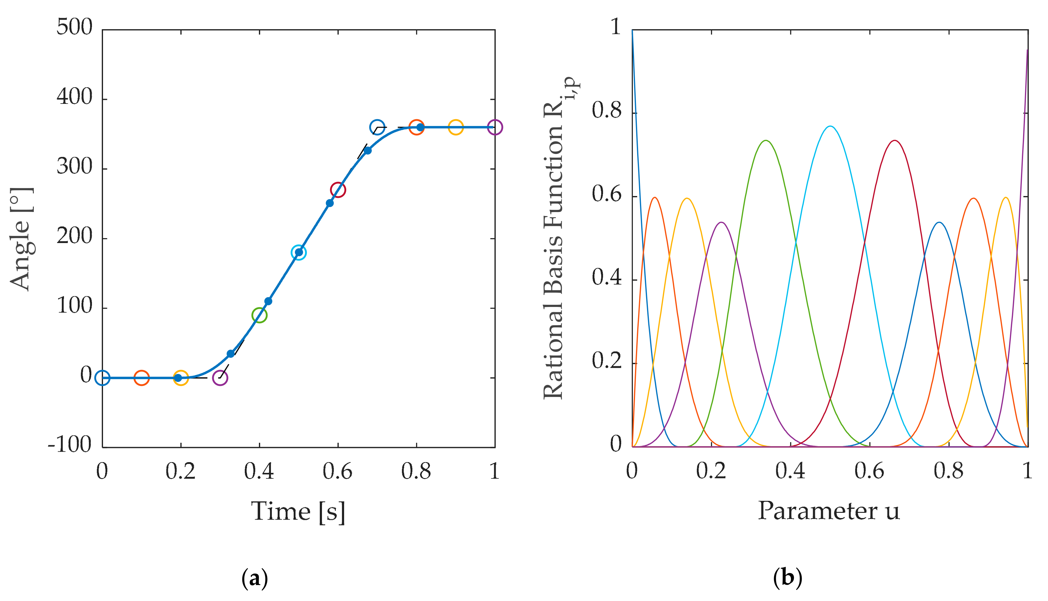
An example of a 2D cubic NURBS curve is given in
Figure 2a. Here, the eleven control points are represented by circles. The dashed line between the control points is the so-called control polygon. The cubic NURBS curve consists of eight segments, which are divided in
Figure 2a by points.
Figure 2b shows the rational basis function
for a weighting vector
. The color of each rational basis function matches the color of the corresponding control point in
Figure 2a. The higher the weights of the control points, the higher the peaks of the corresponding rational basis function. Both the control points and the weights have a high impact on the NURBS curve and thus can be used to manipulate the curve. In addition, the knot vector
has an influence on the NURBS curve [
24]. Since the effect of the knot vector in comparison to the control points and the weights is low, MechDev always uses a uniform spaced knot vector for
.
In order to use NURBS to model a periodic input motion, the boundary conditions of NURBS at the beginning and the end cannot be arbitrary.
Figure 2a, for instance, shows a rotary input motion with a period duration of one second. After one period, the angle
has to be equal to 360°. The velocity
, as well as the acceleration
, at the end and at the beginning of each period have to be the same. For a period duration of
, these boundary conditions are presented by Equations (2)–(5).
Due to boundary condition (2), the first control point has to be equal to
. Due to boundary condition (3), the last control point has to be equal to
. The velocity at the beginning can be manipulated by the second control point
. The velocity at the end can be manipulated by the second last control point
. To fulfill the requirement of Equation (4), Equations (6) and (7) have to be met under consideration of Equation (8). These equations depend on the velocity
, the order of the NURBS
, as well as on the weights
and the knot vector
(
is equal to the length of the knot vector).
The third control point
, as well as the third last control point
, have an influence on the acceleration
. To force a specific acceleration
at the beginning and at the end of the NURBS, one has to choose those control points as given in (9) and (10) under consideration of Equations (11)–(14).
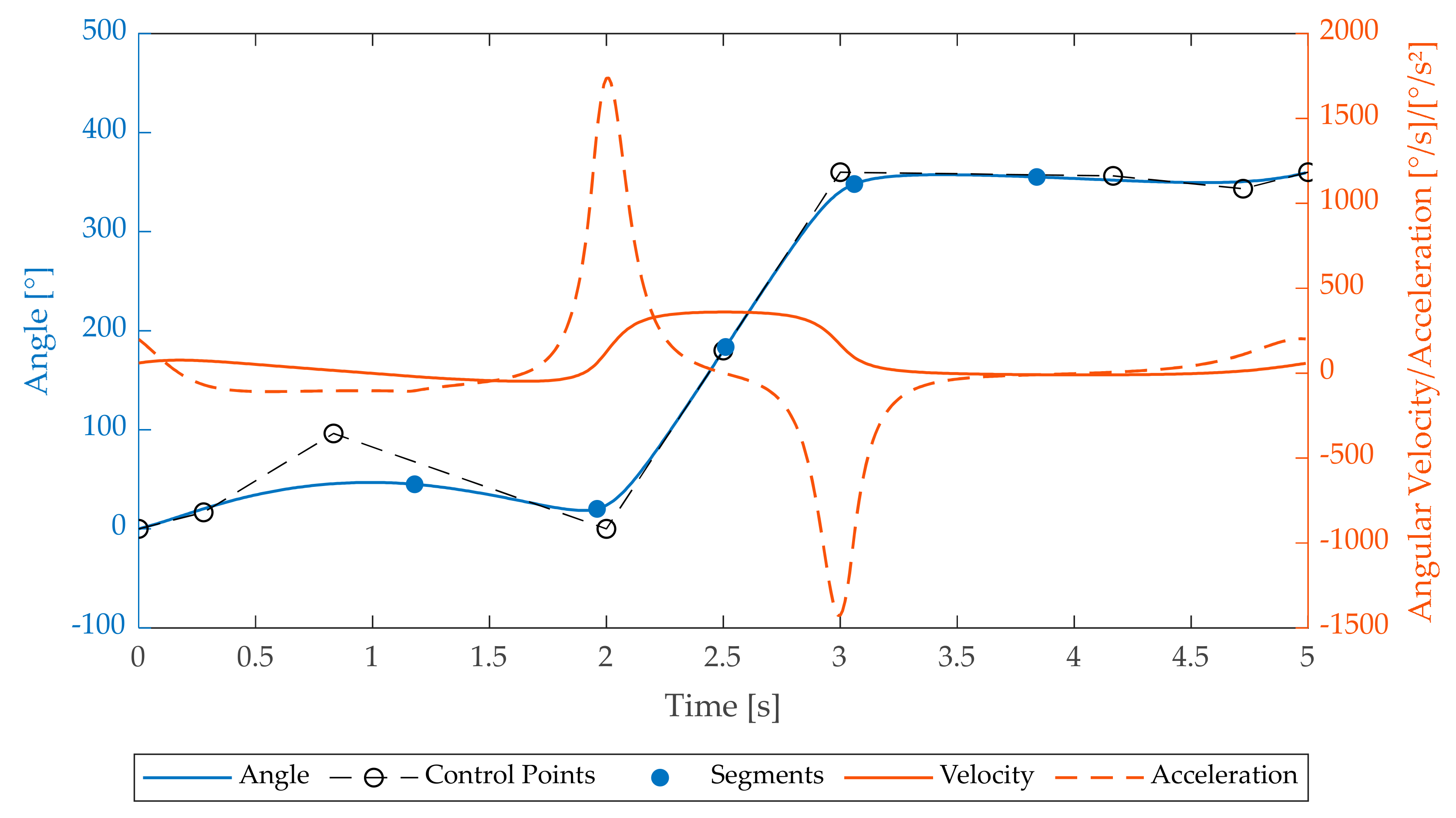
Figure 3 shows an example of a periodic NURBS curve defined in MechDev by five control points and their weights given in (15), as well as the boundary condition of
and
.
To achieve the boundary conditions mentioned above, one has to add two control points at the beginning and two control points at the end of the NURBS. Calculated by the previous equations, these control points are given by (16).
4. Optimization of the Transmission Angle
The combination of servo drives with cam mechanisms can lead to an improvement of the properties of these mechanisms. Among others, the transmission angle of the cam mechanism is one of these properties. The advantages of such a combination have been shown in previous publications, such as [
27,
28,
29].
The idea to consider an actuation of cam mechanisms with variable input motion in the synthesis process first was described by ROTHBART in 1956 [
30]. The variable input speed was realized by an inverted slider crank mechanism in order to improve the transmission angle for an output motion with a long dwell. In that approach, the variation of the input motion was limited by the kinematical dimensions of the inverted slider crank mechanism. Nowadays, servo drives provide the possibility to define almost arbitrary input motions. Hence, there are nearly no limitations to the definition of input motion.
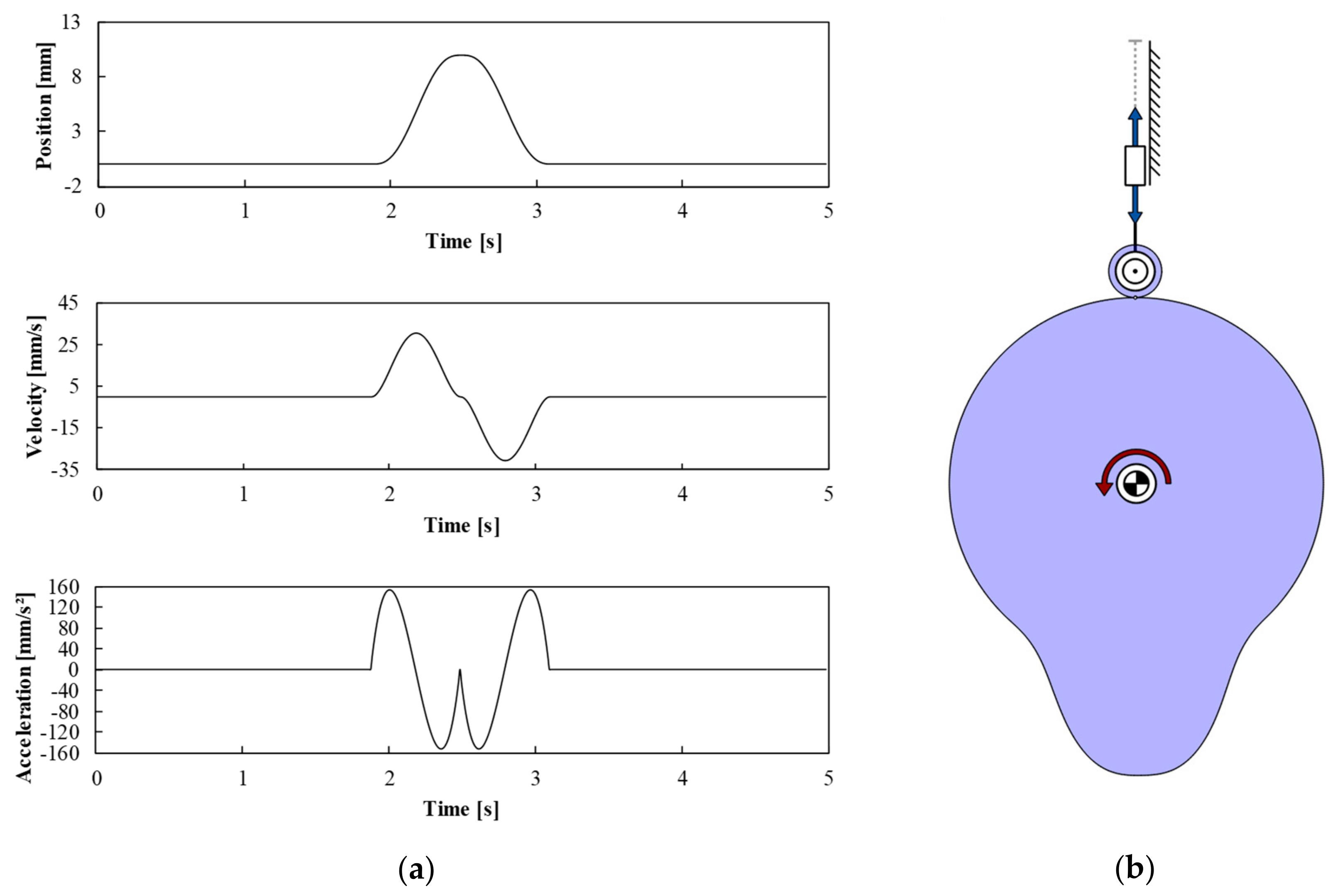
In the following, three different mechanisms will be analyzed and compared in MechDev. All of them provide the same translating output motion with a long dwell. This output motion is shown in
Figure 4a. It consists of four fifth degree polynomial segments.
The first mechanism is the classical cam mechanism with constant input motion. The second mechanism is the one described by ROTHBART in [
30]. The last one is a mechanism that is actuated by a servo drive. Even if the output motions of the named mechanisms are the same, they differ in their cam disks because of their different input motions.
MechDev calculates the cam curvature based on the input motion as well as the output motion. The resulting mechanism with a constant input motion is shown in
Figure 4b.
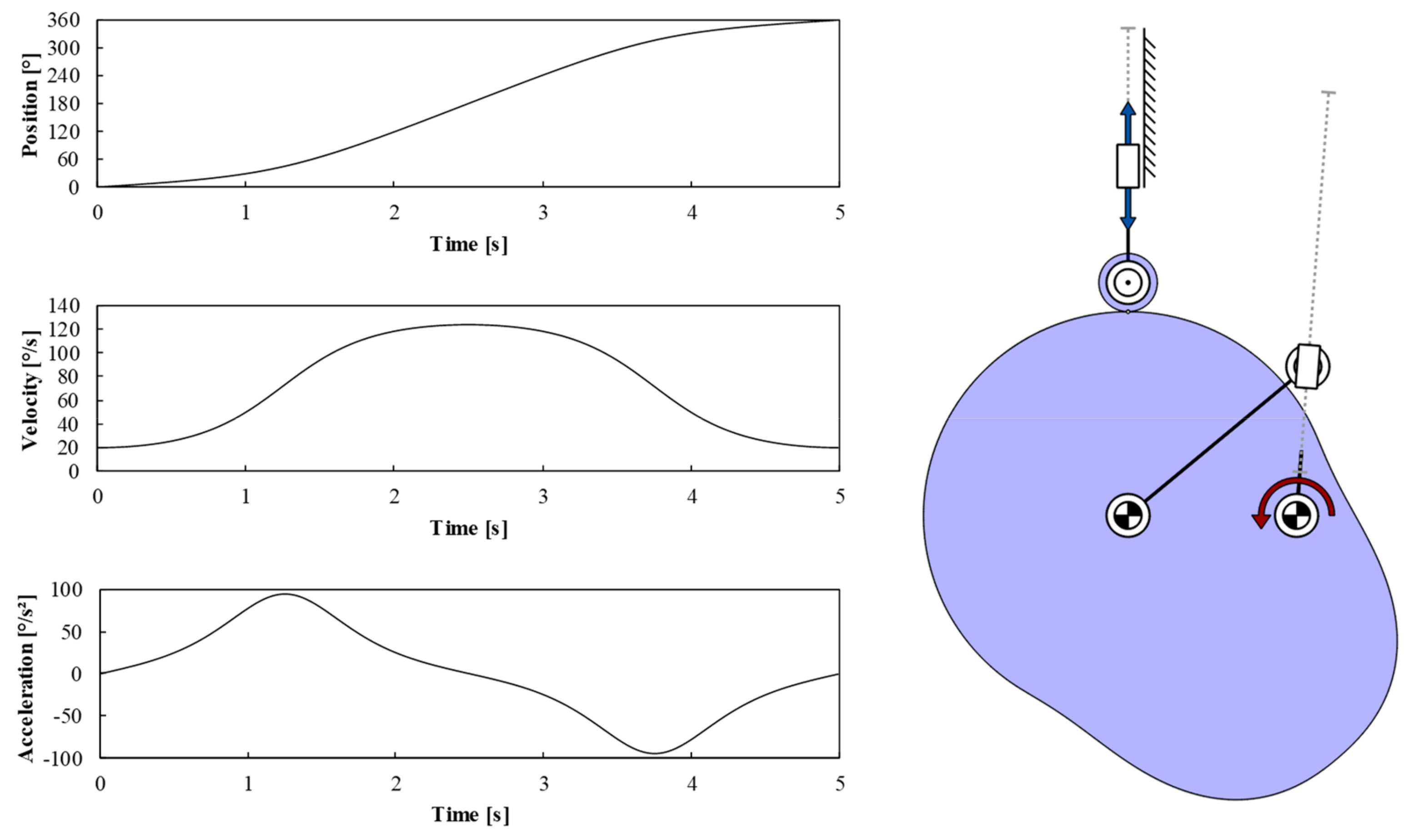
The mechanism by ROTHBART has to realize the same output motion, shown in
Figure 4a. This mechanism is composed of two parts. The first part is an inverted slider crank that can be actuated with constant input motion. The output link of the inverted slider crank is directly connected to the cam itself. This results in a non-constant rotation speed of the cam. The rotational input motion of the cam disk is shown in the diagrams on the left-hand side of
Figure 5. The resulting mechanism synthesized by MechDev is shown on the right-hand side of
Figure 5.
The input motion of the cam shows a higher velocity during the rise and fall of the follower. This leads to a cam with lower curvatures as well as bigger transmission angles in comparison to the mechanism with constant input velocity, as shown in
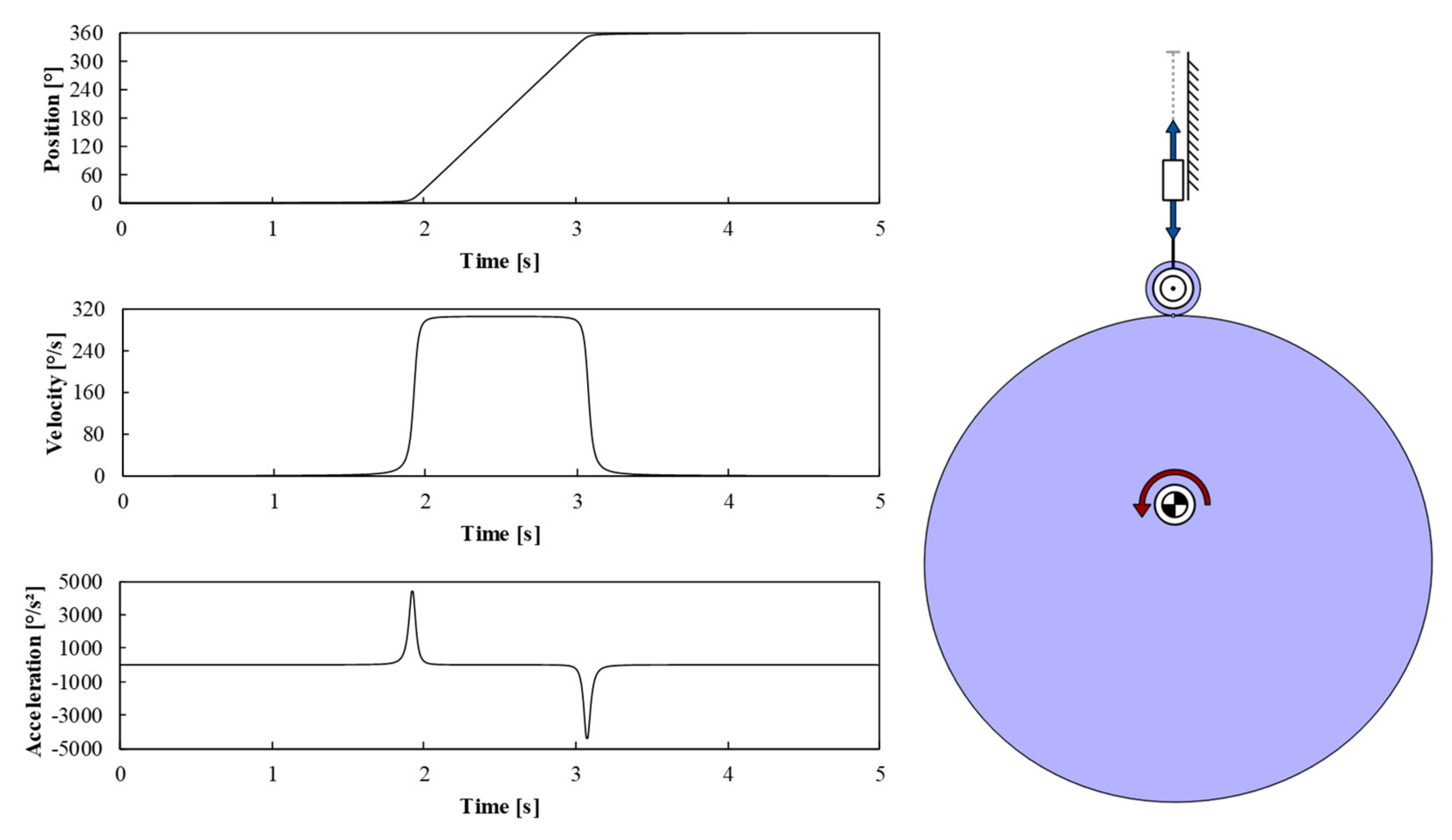
Figure 4b. By actuating the cam mechanism with a servo drive, the effect of the ROTHBART mechanism can be amplified. As described in the previous section, MechDev provides NURBS for the flexible generation of input motions. The control points and weights of NURBS can be modified to fit the desired motion [
24]. An example of such a motion is shown on the left-hand side of
Figure 6. During the dwells of the slider, the cam disk has nearly no rotational velocity. During the translating motion of the slider, the cam accelerates to a maximum speed and then decelerates again. The resulting mechanism is shown on the right-hand side of
Figure 6. In comparison to the previous mechanism, the minimal curvature of the cam disk is smaller.
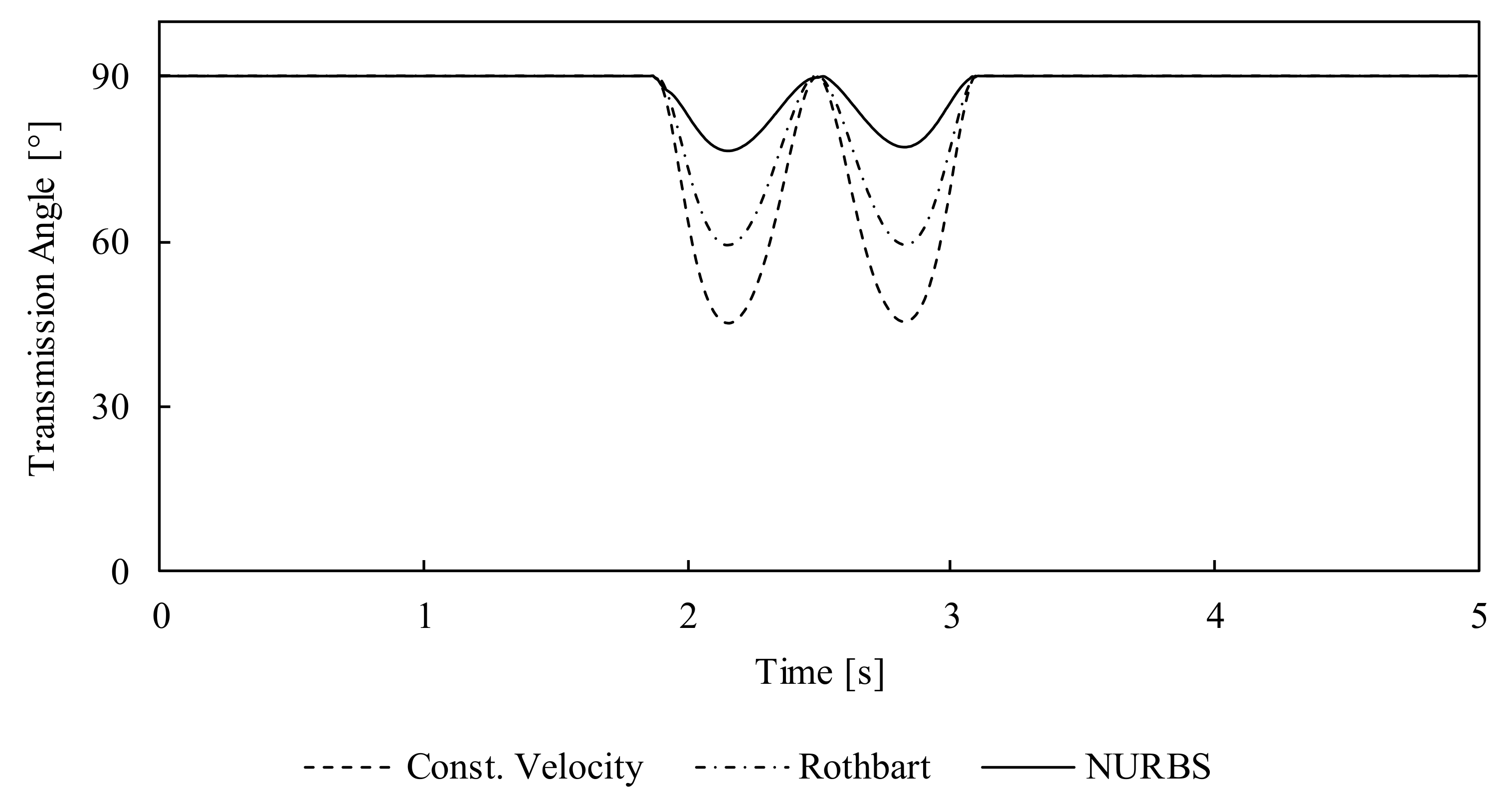
Besides the improvement of the cam curvature, it is also possible to improve the transmission angle by the variation of the input speed. The transmission angle of the three shown mechanisms can be compared in MechDev. The resulting transmission angles of the mechanism are shown in
Figure 7.
This figure shows that a variation in the input velocity of a cam can drastically improve the transmission angle. The minimal transmission angle of the mechanism with a constant rotational velocity is around 45°. The actuation with an inverted slider crank increases the minimal transmission angle to approx. 60°. The NURBS-based cam has a minimal transmission angle of approx. 77° and hence is closer to the optimal transmission angle of 90°. Since the properties of the NURBS are chosen in order to optimize the minimal transmission angle of the cam mechanism, other properties, such as the maximal acceleration, are not focused. This leads to comparatively large accelerations. Nevertheless, the NUBRS-based mechanism gives an impression about the best possible solution regarding the criterion of the minimal transmission angle.
5. Conclusions
This paper sums up most of the functionalities provided by the mechanism design software “Mechanism Developer” (MechDev). So far, the kinematical and kinetostatical analysis methods are the core-functionalities. Due to the optimized calculation time of the algorithms, changes in kinematic parameters can be visualized in quasi-real-time. Therefore, the user has the possibility to optimize mechanisms via drag-and-drop. Besides these core-functionalities, MechDev provides powerful methods to analyze and synthesize cam mechanisms.
The presented use-case based on [
28] has been implemented in MechDev. The optimization of the input motion of a cam mechanism using NURBS improved not only the curvature of the cam but also the transmission angle.
It is planned to integrate more mechanism-based functionalities into MechDev. One of these functionalities will be algorithms for the synthesis of linkages based on revolute and prismatic joints.


