Design to Achieve Accuracy in Ink-Jet Cylindrical Printing Machines


Abstract
:1. Introduction
2. Methodology
3. Topologies
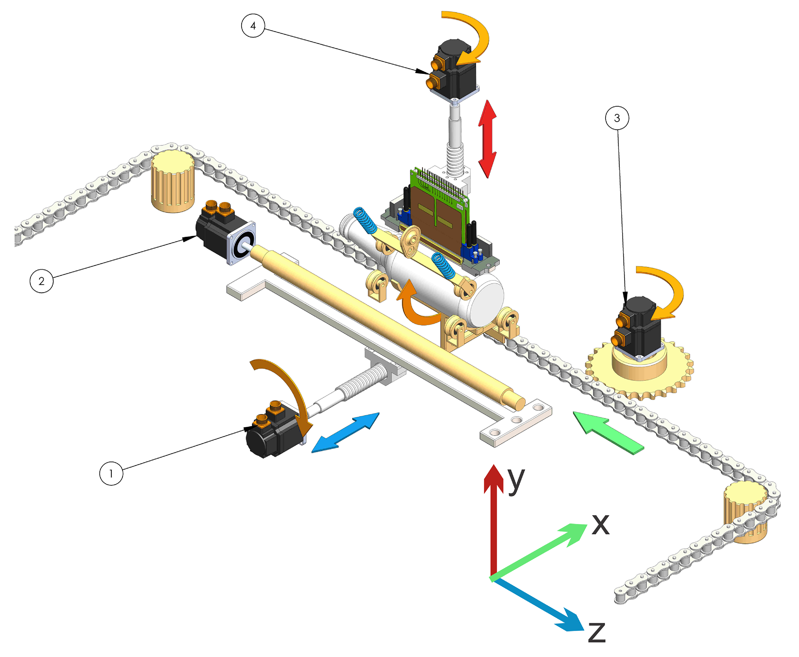
3.1. Topology 1
3.2. Topology 2
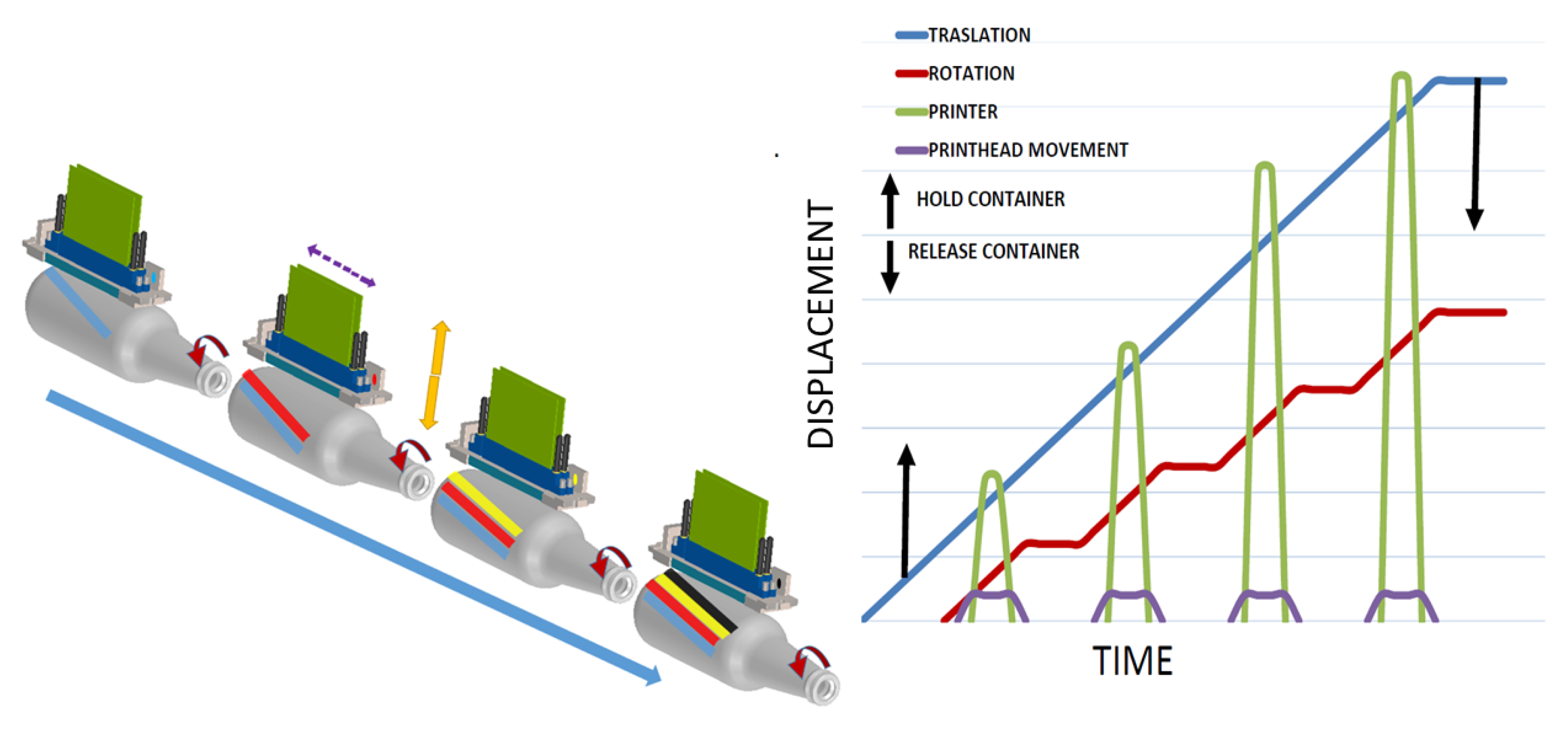
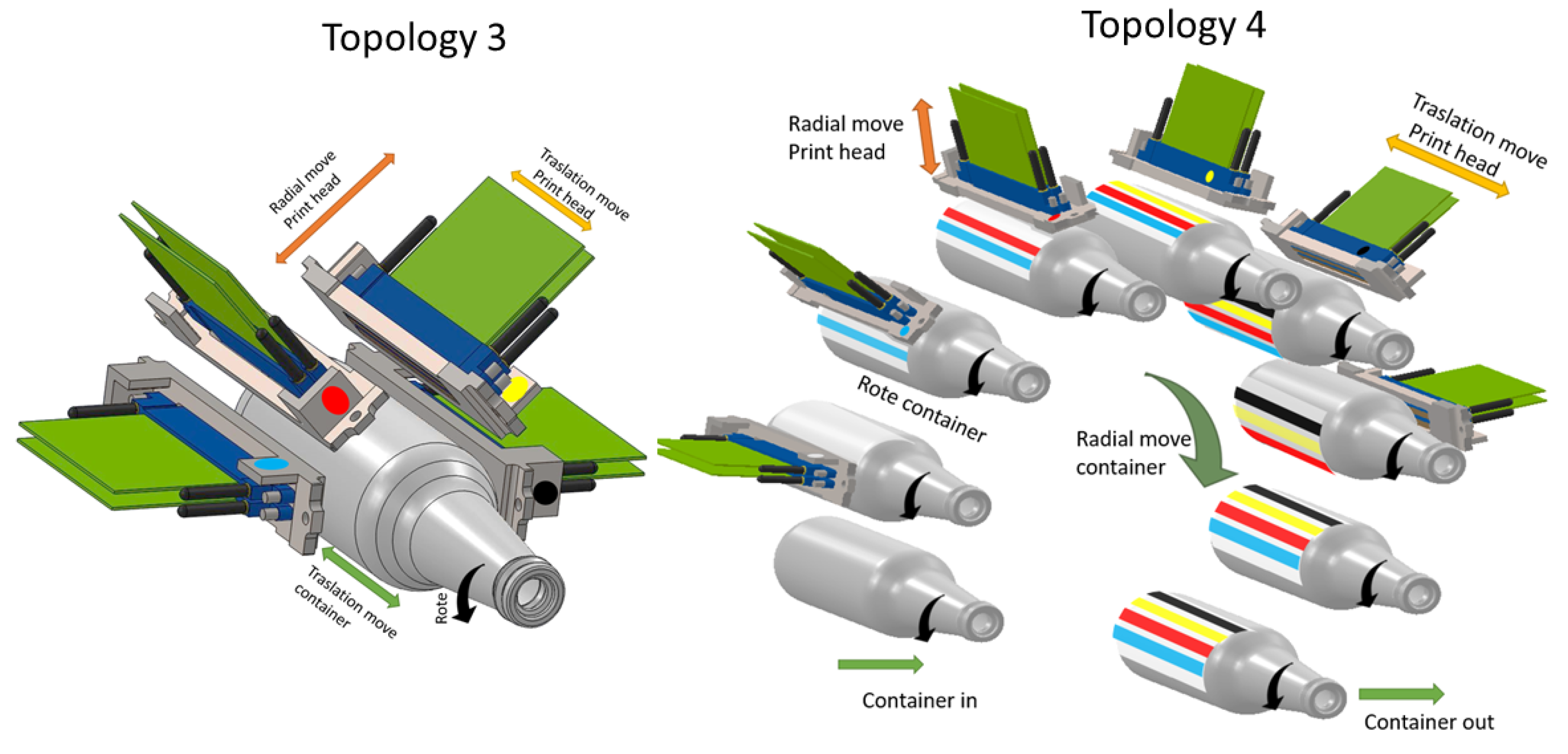
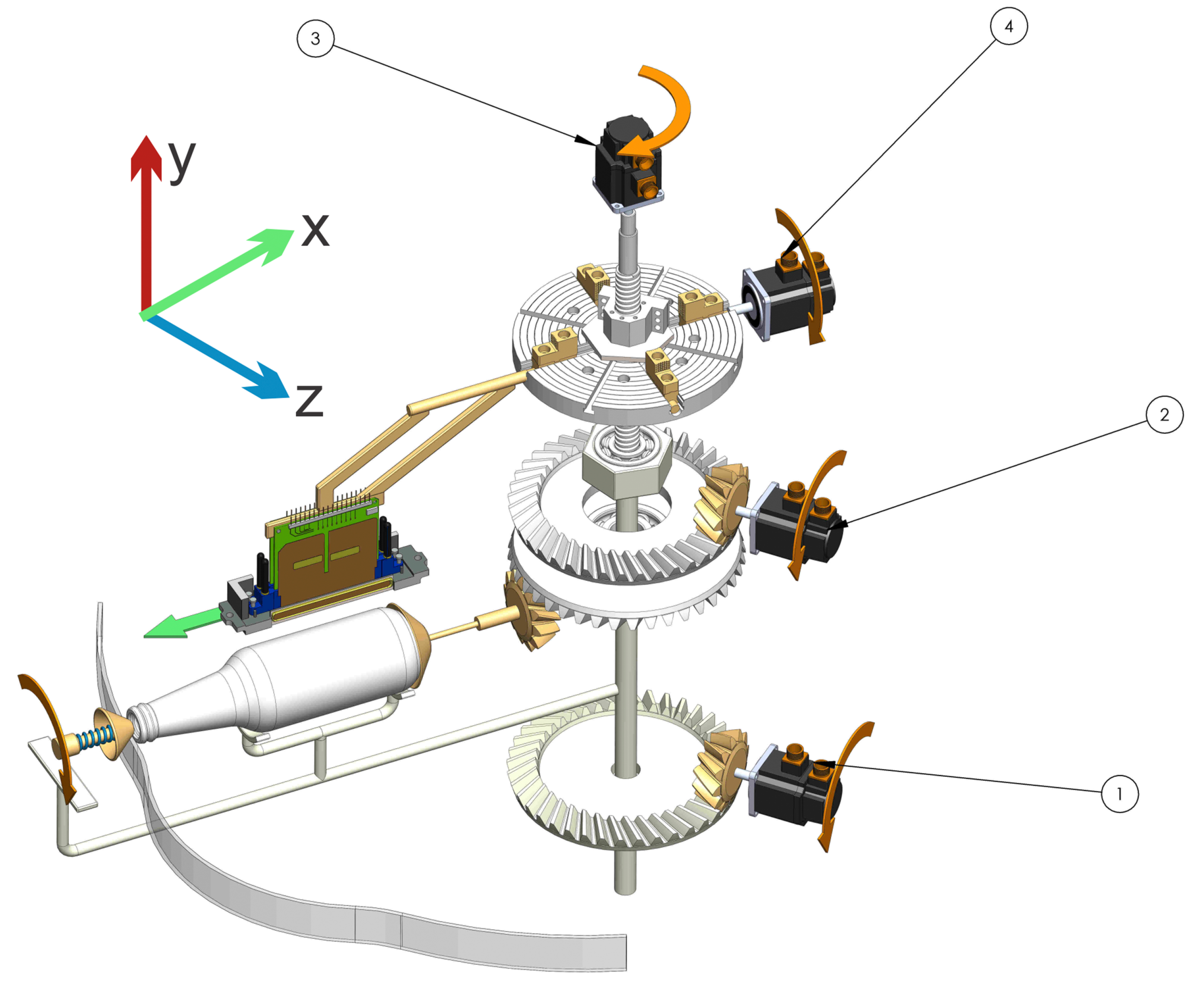
3.3. Topology 3
3.4. Topology 4
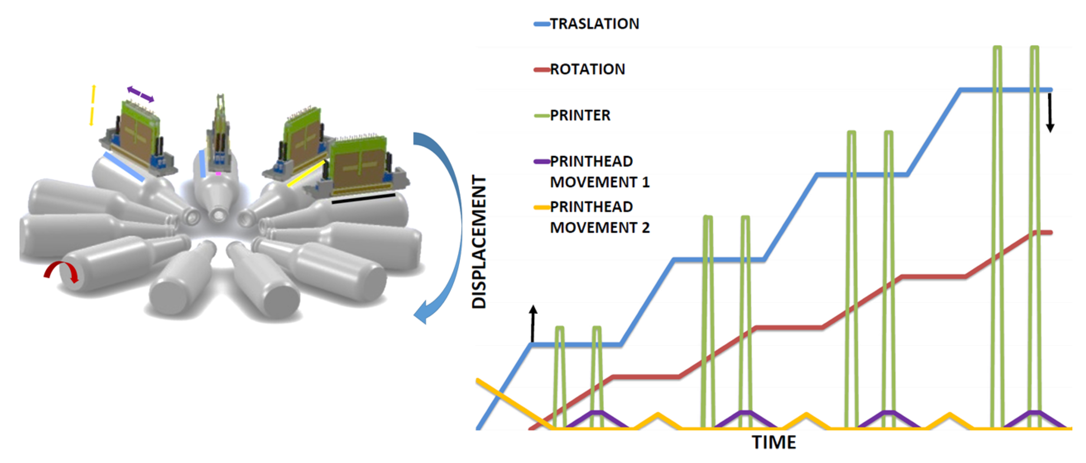
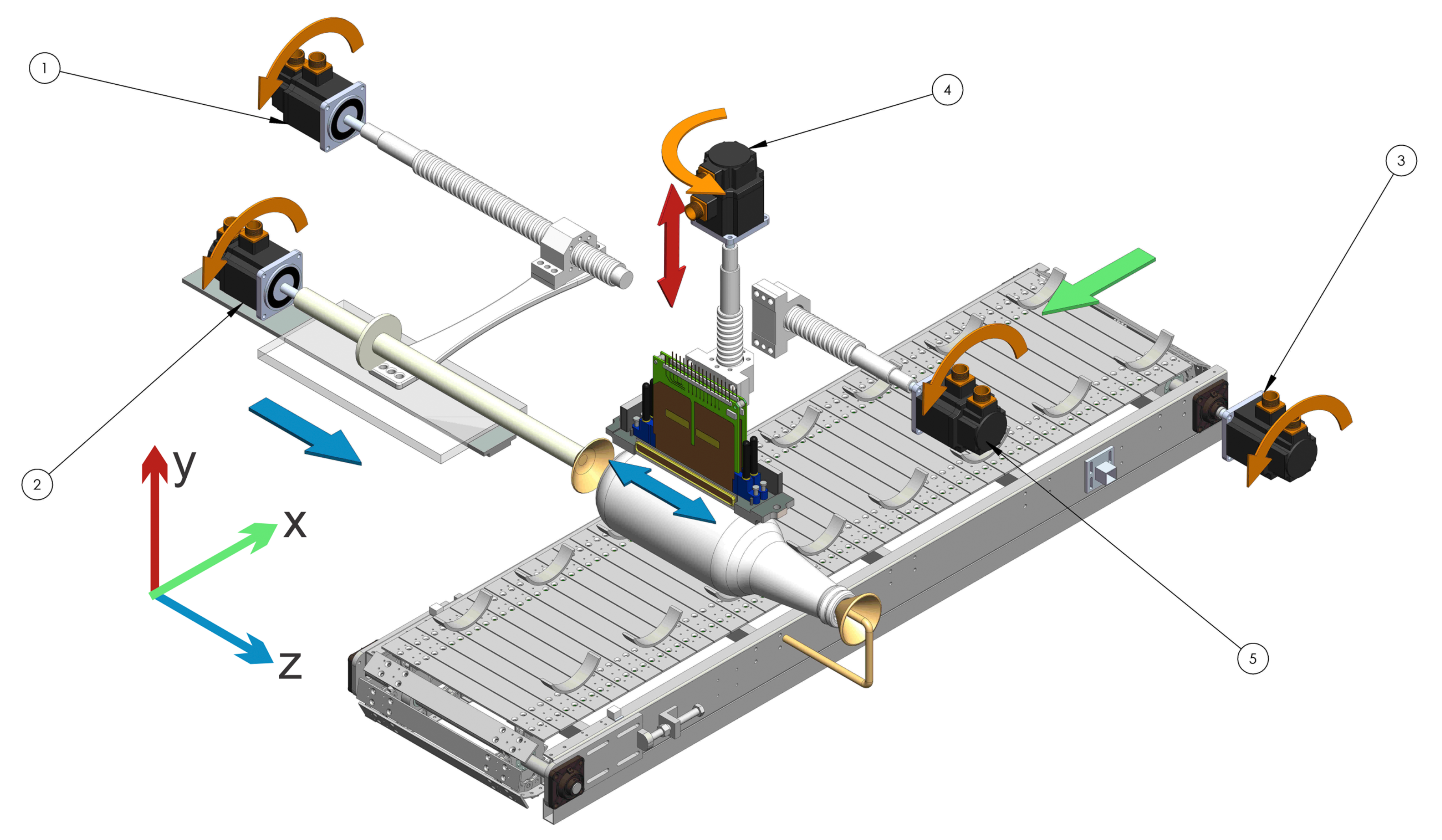
3.5. Topology 5
4. Error in Printing Quality
4.1. Error in Printing Quality in Topology 1
- : Number of elements of the topology i
- : accumulated error topology i
- : element error type n
- p: values near 1 for optimistic estimations and values near 2 for conservative estimations
4.2. Error in Printing Quality in Topology 2
4.3. Error in Printing Quality in Topology 5
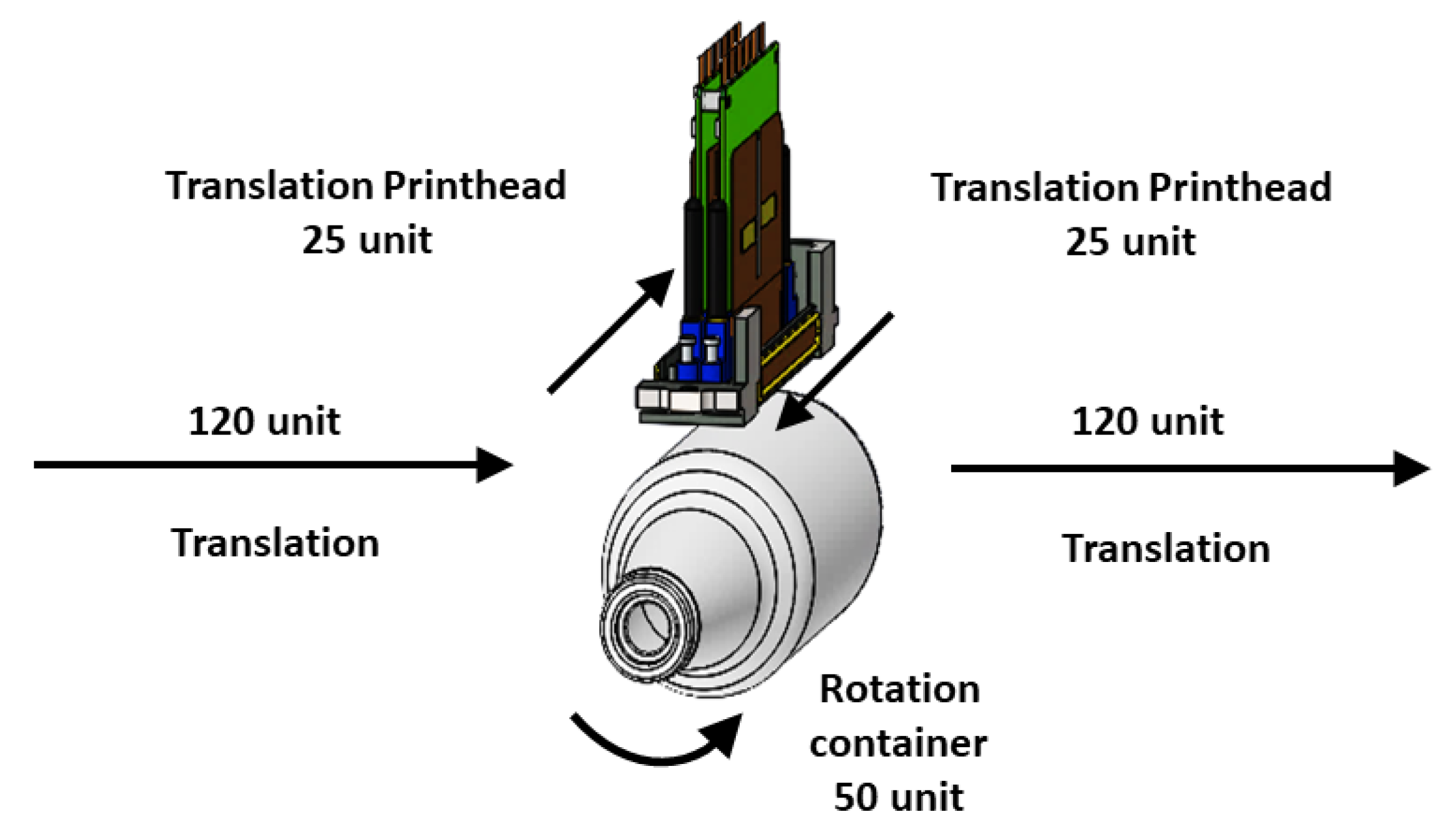
5. Print Time
- process time for one color: “PT”
- print head translation time: “phtt”
- container traslation time: “ctt”
- container rotation time: “crt” (note in this moment the print head is printing)
6. Conclusions
Author Contributions
Funding
Conflicts of Interest
References
- Cohen, G. UV/EB Market Trends. RadTech Rep. 2012, 26, 44. [Google Scholar]
- Porras, R.; Alonso, W.; Pinto Hernández, J.A. Caracterización de la Logística de la Cadena de Abastecimiento de Envases, Empaques y Embalajes de Plástico en Bogotá; Trabajo de grado; Universidad Distrital Francisco José de Caldas: Bogotá, Colombia, 2016. [Google Scholar]
- Wilhelm, H. A 15-year history of digital printing technology and print permanence in the evolution of digital fine art photography–from 1991 to 2006. In NIP & Digital Fabrication Conference; Society for Imaging Science and Technology: Springfield, VA, USA, 2006; Volume 2006, pp. 308–315. [Google Scholar]
- Polonsky, M.J.; Bailey, J.; Baker, H.; Basche, C.; Jepson, C.; Neath, L. Communicating environmental information: Are marketing claims on packaging misleading? J. Bus. Eth. 1998, 17, 281–294. [Google Scholar] [CrossRef]
- Thorp, D. Exploring the Digital Decoration of 3D Surfaces; Technical Report; Business Development Director SGIA Industrial Printing Symposium: Fairfax, VA, USA, 2016. [Google Scholar]
- Yin, Z.; Huang, Y.; Bu, N.; Wang, X.; Xiong, Y. Inkjet printing for flexible electronics: Materials, processes and equipments. Chin. Sci. Bull. 2010, 55, 3383–3407. [Google Scholar] [CrossRef]
- Mercier, C.; Morel, O.; Fox, J.; Todd, R.; MacDonald, L. Influence of the Rotation of Inkjet Printing Heads on the Print Quality. In NIP & Digital Fabrication Conference; Society for Imaging Science and Technology: Springfield, VA, USA, 2009; Volume 2009, pp. 103–106. [Google Scholar]
- Lin, B.W. Original equipment manufacturers (OEM) manufacturing strategy for network innovation agility: The case of Taiwanese manufacturing networks. Int. J. Prod. Res. 2004, 42, 943–957. [Google Scholar] [CrossRef]
- Ghosh, M.; John, G. When should original equipment manufacturers use branded component contracts with suppliers? J. Mark. Res. 2009, 46, 597–611. [Google Scholar] [CrossRef]
- Buendia, F. Business Competition as a Self-organizing Process: Toward an Increasing Returns-Based Microeconomic Theory. In Economics: Complex Windows; Springer: Berlin, Germany, 2005; pp. 123–147. [Google Scholar]
- Cahill, V.; Giraud, P. The State of Inkjet Printheads & Applications (Abridged). In NIP & Digital Fabrication Conference; Society for Imaging Science and Technology: Springfield, VA, USA, 2010; Volume 2010, pp. 36–39. [Google Scholar]
- Morgavi, P. Panasonic Print Head Technology and Market Applications. In Proceedings of the IMI Europe, Digital Printing Conferences 2007, Barcelona, Spain, 20–21 September 2007; p. 2007. [Google Scholar]
- Poozesh, S.; Saito, K.; Akafuah, N.K.; Graña-Otero, J. Comprehensive examination of a new mechanism to produce small droplets in drop-on-demand inkjet technology. Appl. Phys. A 2016, 122, 110. [Google Scholar] [CrossRef]
- Prashanth, H.; Shashidhara, H.; KN, B.M. Image scaling comparison using universal image quality index. In Proceedings of the 2009 International Conference on Advances in Computing, Control, & Telecommunication Technologies, ACT’09, Trivandrum, India, 28–29 December 2009; IEEE: Piscataway, NJ, USA, 2009; pp. 859–863. [Google Scholar]
- Scoutaris, N.; Ross, S.; Douroumis, D. Current trends on medical and pharmaceutical applications of inkjet printing technology. Pharm. Res. 2016, 33, 1799–1816. [Google Scholar] [CrossRef] [PubMed]
- Blazincic, M. Physics of Ink-jet Printing; University of Ljubljana: Ljubljana, Slovenia, 2008. [Google Scholar]
- Pahl, G.; Beitz, W. Engineering Design: A Systematic Approach; Springer Science & Business Media: Berlin, Germany, 2013. [Google Scholar]
- Buur, J. A Theoretical Approach to Mechatronics Design. Ph.D. Thesis, Technical University of Denmark (DTU), Lyngby, Denmark, 1990. [Google Scholar]
- Chan, D. Development of an Inkjet Printing System on a Flatbed Router. Master’s Thesis, University of Waterloo, Waterloo, ON, Canada, 2010. [Google Scholar]
- Arango, I.; Pineda, F. Desarrollo de Tecnología para la fabricación de máquinas CNC para corte de tendidos de tela para pequeños talleres de confección. Tecno Lógicas 2010, 25, 11–30. [Google Scholar] [CrossRef]
- Adams, K. Non-Functional Requirements in Systems Analysis and Design; Springer: Berlin, Germany, 2015; Volume 28. [Google Scholar]
- Yang, M.T.; Chiu, C.H.; Lo, C.B.; Chen, C.J.; Chou, P.F.; Wu, K.H. A Novel Method for Evaluating Ink-Jet Print Head Directionality. In NIP & Digital Fabrication Conference; Society for Imaging Science and Technology: Springfield, VA, USA, 2004; Volume 2004, pp. 393–398. [Google Scholar]
- Feeney, A.B.; Frechette, S.P.; Srinivasan, V. A portrait of an ISO STEP tolerancing standard as an enabler of smart manufacturing systems. J. Comput. Inf. Sci. Eng. 2015, 15, 021001. [Google Scholar] [CrossRef]
- Hosseinkhani, Y. Control Methods for Improving Tracking Accuracy and Disturbance Rejection in Ball Screw Feed Drives; UWSpace: Waterloo, ON, Canada, 2014. [Google Scholar]
- Hale, L.C. Principles and Techniques for Designing Precision Machines; Technical Report; Lawrence Livermore National Lab.: Livermore, CA, USA, 1999. [Google Scholar]
- Perelaer, J.; Smith, P.J.; van den Bosch, E.; van Grootel, S.S.; Ketelaars, P.H.; Schubert, U.S. The Spreading of Inkjet-Printed Droplets with Varying Polymer Molar Mass on a Dry Solid Substrate. Macromol. Chem. Phys. 2009, 210, 495–502. [Google Scholar] [CrossRef]
- Majithia, A.; Hall, S.; Harper, L.; Bowen, P. Droplet breakup quantification and processes in constant and pulsed air flows. In Proceedings of the 22nd Conference on Liquid Atomization and Spray Systems (ILASS-Europe), Como Lake, Italy, 8–10 September 2008; Available online: http://www.ilasseurope.org/ICLASS/ILASS2008_COMO/file/papers/4-4.pdf (accessed on 13 July 2018).
- van Hoeve, W.; Gekle, S.; Snoeijer, J.H.; Versluis, M.; Brenner, M.P.; Lohse, D. Breakup of diminutive Rayleigh jets. Phys. Fluids 2010, 22, 122003. [Google Scholar] [CrossRef] [Green Version]
- Profactor. Profactor Company, 2018. Available online: https://www.profactor.at (accessed on 30 December 2018).
- Lebensmittel, Pharma, Luxusgüter. Heidelberger Company, 2018. Available online: https://www.heidelberg.com (accessed on 30 December 2018).
- INX International Company Home Page, Meteor Inkjet, 2018. Available online: https://www.inxinternational.com (accessed on 3 June 2018).
- Krause, J. Color Index 2: Over 1500 New Color Combinations. For Print and Web Media. CMYK and RGB Formulas; HOW Books: Ljubljana, Slovenia, 2007; Volume 7. [Google Scholar]
- Bruijnen, D.; van de Molengraft, R.; Draad, A.; Heeren, T. Productivity analysis of a scanning inkjet printer. In NIP & Digital Fabrication Conference; Society for Imaging Science and Technology: Springfield, VA, USA, 2005; Volume 2005, pp. 129–132. [Google Scholar]


| Motor 1 | Screw Ball Recirculating 1 | Motor 2 | Motor 3 | Band | Motor 4 | Screw Ball Recirculating 4 | Motor 5 | Screw Ball Recirculating 5 | Conical Surfaces | Total | |
| Topology 1 | |||||||||||
| Rotation container | 5 | 5 | 100 | 110 | |||||||
| X container | 5 | 100 | 105 | ||||||||
| Y container | 5 | 50 | 55 | ||||||||
| Z container | 5 | 50 | 5 | 50 | 250 | 360 | |||||
| Topology 2 | |||||||||||
| Rotation container | 5 | 5 | |||||||||
| X container | 5 | 100 | 105 | ||||||||
| Y container | 5 | 50 | 55 | ||||||||
| Z container | 5 | 50 | 55 | ||||||||
| Topology 5 | |||||||||||
| Motor 1 | Crown Gear 1 | Motor 2 | Motor 3 | Screw Ball Recirculating 3 | Motor 4 | Chuck Mechanism 4 | Crown Gear 2 | Cam Mechanism | ____ | total | |
| Rotation container | 5 | 100 | 105 | ||||||||
| angular traslation | 5 | 100 | 105 | ||||||||
| Radial traslation | 5 | 50 | 50 | 105 | |||||||
| Y container | 5 | 50 | 55 |
© 2019 by the authors. Licensee MDPI, Basel, Switzerland. This article is an open access article distributed under the terms and conditions of the Creative Commons Attribution (CC BY) license (http://creativecommons.org/licenses/by/4.0/).
Share and Cite
Arango, I.; Cifuentes, C. Design to Achieve Accuracy in Ink-Jet Cylindrical Printing Machines. Machines 2019, 7, 6. https://doi.org/10.3390/machines7010006
Arango I, Cifuentes C. Design to Achieve Accuracy in Ink-Jet Cylindrical Printing Machines. Machines. 2019; 7(1):6. https://doi.org/10.3390/machines7010006
Chicago/Turabian StyleArango, Ivan, and Catherine Cifuentes. 2019. "Design to Achieve Accuracy in Ink-Jet Cylindrical Printing Machines" Machines 7, no. 1: 6. https://doi.org/10.3390/machines7010006