Article

Optimization of Gerotor Pumps with Asymmetric Profiles through an Evolutionary Strategy Algorithm

Department of Mechanical and Aerospace Engineering, Politecnico di Torino, 10129 Torino, Italy
*
Author to whom correspondence should be addressed.
Machines 2019, 7(1), 17; https://doi.org/10.3390/machines7010017
Submission received: 29 January 2019 / Revised: 20 February 2019 / Accepted: 22 February 2019 / Published: 1 March 2019

Abstract

:
Gerotor pumps are widely used for fuel and lubricating oil distribution, since they provide an economic and compact solution for low-pressure fluid systems. Made of two internally coupled gears, their behavioral and operative performances are strictly tied to their geometrical designs. Traditionally, the external gear features circular lobes that give origin to a cycloidal profile for the internal rotor. In this paper, the use of profiles based on asymmetric lobes made of elliptic arcs is further explored and expanded. At first, a complete mathematical framework describing the pump geometry and its dynamic behavior is provided, while algorithms used to compute a selected number of performance indexes are presented and when possible, verified. Hence, a single-objective optimization procedure is applied to the traditional cycloidal profile, in order to minimize each of the following quantities: the flow rate irregularity, the expected wear rate, and the estimated rotor mass. Finally, a multi-objective optimization process based on evolutionary strategy is employed, to obtain several asymmetric profiles minimizing the combination of two or more performance indexes. The results are hence compared, and the merits associated with the use of asymmetric lobes are presented.

1. Introduction

Gerotor pumps are obtained through the use of two internal spur gears. The external rotor features N lobes, while the inner one just features only N−1 lobes. The volume variation of the N isolated chambers along a complete rotation of the external rotor allow for fluid suction and delivery, as sketched in Figure 1. This peculiar configuration allows for extremely compact and reliable devices to be obtained, which have hence become one of the preferred choices for low-pressure systems in mobile applications [1,2,3,4].
The first study on the use of two conjugated gears for fluid pumping applications can be found in the work published by J.R. Colbourn in 1974 [5]. Almost 20 years later, the works of Beard [6,7,8] and Shung [9], focusing on the mathematical description of the profiles and on the trade-off between several geometrical solutions, sparked a huge research effort aimed at the automation of the design process, and at the improvement of the pump performances. With regard to the first subject, it is important to underline the studies by Litvin, who applied the theory of gearing [10] to cycloidal gerotors in [11], providing a general mathematical framework that is able to describe any kind of rotor profile, and to describe the geometrical conditions that may cause discontinuities in the gear profiles. Other formulations on the same problem, including an original geometrical interpretation by Mimmi, can be found in [12,13,14], while the pump dynamics has been investigated by Ivanovic and colleagues [15,16,17].
The dependence of the pump performances over the rotors geometry was first addressed by Hsieh [18,19,20]. Several lobe geometries, such as elliptic, sinusoidal, poly-circular, and parabolic, have been studied by Mancò [1] and Mimmi [21], while Bonandrini [22,23] and Demenego [24] focused on research for novel rotor profiles, to limit the wear rate. To achieve similar objectives, Hsieh recently published an original solution that makes use of variable clearance designs [25]. A significant amount of research on multiple profiles geometries to optimize the pressure angle during the whole contact cycle can be found in [26,27,28,29,30,31,32,33], while a different approach to rotor design, based on straight-line-conjugated profiles can be found in [33,34,35,36]. Other significant contributions to this research field can be found in [37], while a particularly interesting development on a magnetically-driven gerotor is proposed in [38]. In order to overcome some of the traditional issues of gerotor pumps [39], the authors recently proposed a novel solution, based on asymmetric teeth and radial ports, which allows for some significant advantage in systems where the pump is driven in the same direction for the most significant part of its operative life [40]. The present paper further expands this concept, and it is articulated as follows. At first, a general overview of gerotor pumps and the mathematical description of their rotors profile is provided; hence, major design constraints are presented and linked to the profile geometry. A dynamic model of the pump used in the study is presented as well. To assess the merits of the asymmetric profiles, three performance indexes are used: flow rate irregularity, wear rate estimation through the Wear Rate Proportional Factor (WRPF), and rotors mass. At first, several optimization cycles are performed through a provided method for each performance index, over the traditional cycloidal profile. As such, several cycloidal profiles are obtained, each optimizing one performance index for the selected reference speed. Through this first analysis, it is shown that the geometrical parameters allowing for the optimization of a given performance index (i.e., flow rate irregularity) are often extremely different from the ones that optimizing the other performance indexes (i.e., rotors mass). The optimum values here obtained are used as a reference.
The of the authors is to demonstrate that the asymmetric lobes’ geometry can be used to design gerotor pumps able to provide good results over a combination of two or more performance indexes (i.e., wear rate and rotors mass, all three indexes etc.). To do so, several multi-objective optimization cycles have been performed. The related performance indexes are then compared to the ones that are obtained for the traditional profile.

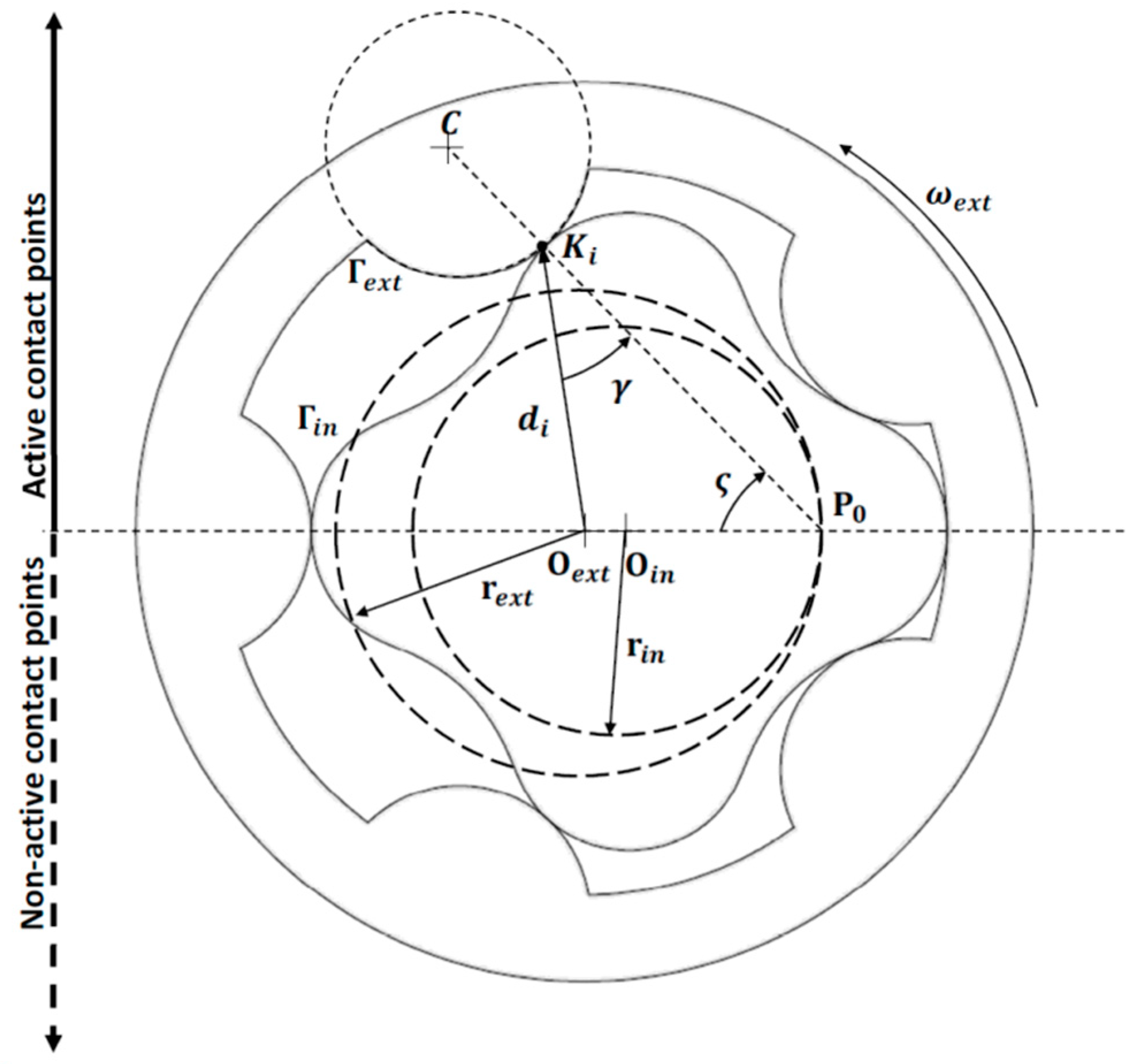
2. General Design Theory for Gerotor Pump Profiles

To define the rotors geometries, the most efficient methods make use of closed form equations specific of certain profile type [1,21]. Although it is simple to implement in automatic procedures without requiring heavy computational effort, those methods have limited applicability, since it is not always possible to describe the inner gear profile through implicit functions [21]. As such, the proposed framework features a more general approach that is based on the theory of gearing [10], and reported by several authors for its flexibility in describing non-circular profiles [11,12]. Following this approach, and looking at Figure 2, three reference frames are introduced: ( x , y ) e x t and ( x , y ) i n are the couples of the axis that are related to the external and to the inner gears, while ( x , y ) f is the still reference frame of an external observer. The ( x , y ) e x t frame and the fixed axis have their origin Oext on the rotational axis of the external gear, while the origin Oint of ( x , y ) i n sits on the rotation axis of the inner gear. The gerotor eccentricity e can hence be defined as the distance between Oext and Oint.
The kinematics of two perfectly meshing gears can be described through a constant transmission ratio τ i e , equal to the ratio between the two pitch dimensions rext and rin, and hence strictly dependent on the eccentricity e, as shown through Equation (1).
τ i e = ω i n ω e x t = r e x t r i n = r e x t r e x t e = N N 1
As shown in Figure 3, it is possible to add a local reference system ( χ , ψ ) for which origin C is related to the rotor geometry through its distance with Oext ( C O e x t ¯ ) and the eccentricity e. Defining the vectors Γin and Γext as the inner rotor profile in the ( x , y ) i n reference system and the external rotor geometry in its ( x , y ) e x t frame, the following conditions must be verified:
{ m a x ( Γ i n ) = C O e x t ¯ ρ χ + e m i n ( Γ i n ) = C O e x t ¯ ρ χ e m a x ( Γ e x t ) = r l i m , e x t = C O e x t ¯ ρ χ + 2 e m i n ( Γ e x t ) = C O e x t ¯ ρ χ
The ratio between C O e x t ¯ and ρ χ is often addressed as λ, and is of critical importance for the profile design [1]. According to Mimmi [21] and as already reported by the authors in [40], the most convenient way to define the lobe geometry is through the use of parametric equations expressed in the local reference system ( χ , ψ ) . Considering the teeth profiles defined by one or more ellipse arcs, the following expression that is dependent on factor k can be considered.
{ χ = ρ χ c o s ( ξ ) ψ = k ρ χ s i n ( ξ )
{ t a n ( ϑ ) = k   t a n ( ξ ) 0 ξ π
r k = C K i ¯ = ρ χ c o s 2 ( ξ ) + k 2 s i n 2 ( ξ )
The final expression of the external profile Γext in its reference frame can be found by repetition around the rotor symmetry axis, given the angular pitch α = ( 2 π ) / N [11].
Γ e x t e x t = [ x e x t y e x t ] = [ c o s ( i Δ α ) s i n ( i Δ α ) s i n ( i Δ α ) c o s ( i Δ α ) ] [ C O e x t ¯ r k c o s ( ϑ ) r k s i n ( ϑ ) ]
where i = 0 ,   1 ,   ,   N 1 .
To obtain the inner rotor profile, the authors make use of the general method that was first introduced by Litvin [10]. This approach makes use of homogeneous coordinates to express the external profile Γext in the ( x , y ) i n frame, by means of the transformation matrix Min,ext [11]:
Γ e x t i n = M i n , e x t [ x e x t y e x t 1 ]
M i n , e x t = [ c o s ( ϕ i n ϕ e x t ) s i n ( ϕ i n ϕ e x t ) e   c o s ( ϕ i n ) s i n ( ϕ i n ϕ e x t ) c o s ( ϕ i n ϕ e x t ) e   s i n ( ϕ i n ) 0 0 1 ]
Applying Equation (1), we have ϕ in = τ ie ϕ ext for ideal meshing. According to [29], it is known that the normal to the meshing teeth profiles in the contact points passes through the center of rotation P0, which coordinates ( X 0 , Y 0 ) in the reference system, ( x , y ) e x t can be expressed as:
{ X 0 = r e x t c o s ( ϕ e x t ) Y 0 = r e x t s i n ( ϕ e x t )
The normal to the external rotor lobes can be described through Equation (10), provided that vector Γext and its first derivative are continuous over their entire domain, and that Γ e x t / ξ 0 [10]:
N e x t = [ N X N Y 1 ] = Γ e x t e x t ξ × k e x t
where kext is a unit vector directed along the zext axis. In order to obtain the correct meshing, the normal to the contact point and the line passing through the contact point and P0 must coincide, leading to the following condition [11]:
f ( ξ , Φ e x t ) = X 0 X e x t Y 0 Y e x t N X N Y = 0
The parametric expression of the inner rotor profile Γin is hence provided, combining Equations (8) and (12):
Γ i n i n : { Γ e x t i n ( ξ , Φ e x t ) = M i n , e x t Γ e x t e x t f ( ξ , Φ e x t ) = 0
The profile continuities can be verified through one of the methods from a selected list of robust algorithms of general application, which can be found in the literature [11,12,14]. Other than the geometrical issues described so far, the design of the rotors’ profiles is also determined by the pump operating conditions. To avoid cavitation, it is in fact necessary to keep the fluid velocity under a limiting value, which can be found from the first approximation defined as [41]:
v l i m = k s 2 ( p i n p v ) ρ
This value mainly depends on the fluid pressure at the inlet port pin the fluid vapor tension at the operating temperature pv, and its density ρ; a safety factor of k s 1 is often added in order to limit or to prevent cavitation inception under unpredictable off-nominal conditions. In gerotor pumps, the highest fluid velocity zones are in proximity to the rotors’ maximum radial dimensions, and since the fluid velocity can be considered in the first approximation to be equal to the linear speed of the pump gears, the maximum radius for the inner rotor rlim,in and the external gear rlim,ext at the reference speed ωin can be computed as:
{ r l i m , i n = 2 ( p i n p v ) ρ ω i n 2 r l i m , e x t = 2 ( p i n p v ) ρ ( ω i n τ i e ) 2
Combining Equations (2), (3), and (14), an important design constraint linking the pump geometry to its operating conditions can be found:
r l i m , i n + e r l i m , e x t 2 ( p i n p v ) ρ ( ω i n τ i e ) 2
A low inlet pressure is also responsible for another design limitation, which is related to the occurrence of incomplete filling of the chambers. This phenomenon can be observed whenever the pressure drop across the inlet port is not high enough to completely fill the variable volume chamber during the suction phase, leading to reduced pump flow rate capability, and to cavitation inception [20]. Slightly modifying the expression reported by Singh [42], it is possible to obtain an estimate of the correct value of the ratio between the gerotor axial length H and the port area that is able to prevent the insurgence of this problem at the rated speed ωin:
H A r = K ( p i n p v ) ρ 1 ω i n d A c h d ϕ i n
where Ar is the inlet port area, Ach is the frontal area of the considered chamber, and ϕ i n is the shaft angular position. K′ is a proportionality factor, depending on the port configuration and on the fluid dynamic conditions. Please notice that for axial port gerotors, the maximum possible value of Ar is equal to Ach.

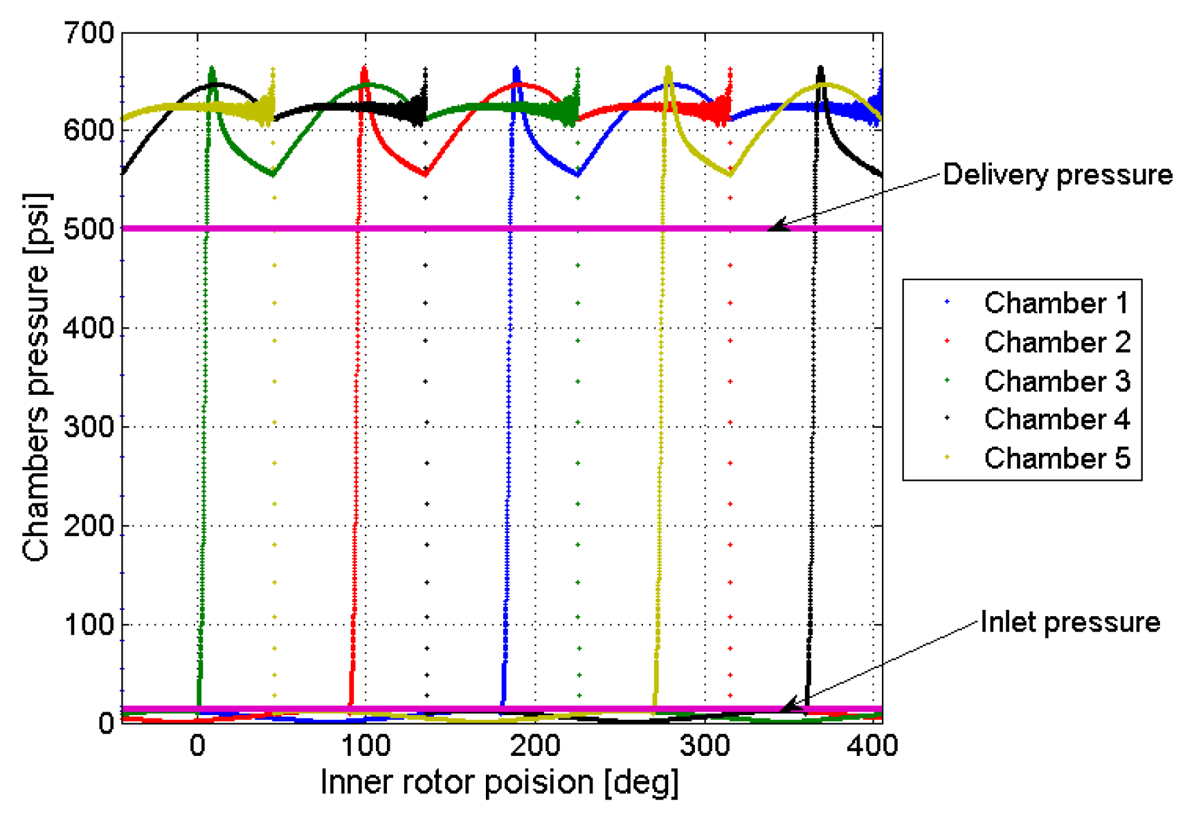
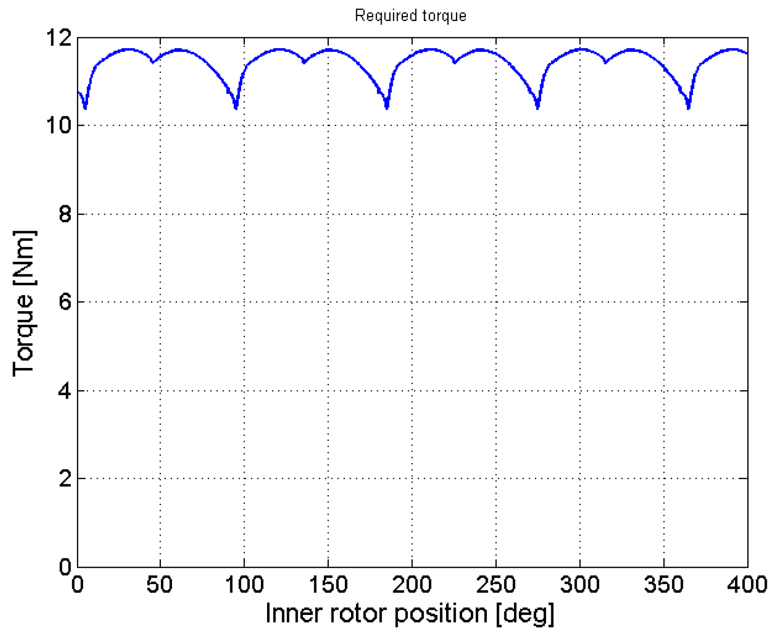
3. Gerotor Dynamic Model

While the equations provided in Section 2 completely define the pump geometry, a dynamic model of the system is required to simulate the gerotor behavior. As shown in Figure 4, three flow rates affecting a generic i-th chamber of Vi volume can be identified. Qp,i is the flow rate exchanged with the external environment, while Qi−1,i and Qi,i+1 are the leakages between the i-th chamber and the adjacent ones.
The flow rate through the i-th port Qp,i depends on the pressure difference between the external environment and the chamber, as well as on the port dimensions and on the fluid properties, according to the following expression [43].
Q p , i = s i g n ( p P p i ) C d A p 2 | p P p i | ρ
where pp and pi are the environmental and chamber pressures, ρ is the fluid density, and Ap is the port area that is seen by the i-th chamber, with a value that is defined by the rotor positions. The discharge coefficient Cd is instead dependent on the fluid Reynolds number that is computed in the port section; its values are obtained through the expressions proposed in [44], and already have been used by authors for steady-state analysis in [40]. Leakages between adjacent chambers are modelled by using the Hagen–Poiseuille law for gaps with rectangular sections [45].
Q i 1 , i = ( p i 1 p i ) H h g 3 12 μ l g
where H is the gerotor axial dimension, hg is the gap height, and lg is the gap length in the direction of the leakage, while μ is the dynamic viscosity of the fluid. The net flow rate across the single chamber Qi can hence be computed through Equation (19), where the adopted sign convention generates positive values during volume filling and negative values during fluid discharge.
Q i = Q p , i + Q i 1 , i Q i , i + 1
Applying the continuity equation to the examined control volume, it is possible to link the net flow rate Qi with the chamber geometry variation, and consequent changes in fluid pressure pi through the Bulk modulus β.
Q i H d A c h d t = V i β d p i d t
where the chamber frontal area Ach is a function of the inner rotor position. The instantaneous flow rate that is delivered by the pump can be computed by summing only the negative contributions of Qi, while paying attention to eventually subtracting the quote, due to leakage between the external rotor and its tracks Qs,r:
Q = i = 1 N Q i | Q i < 0 Q s , r
The leakages between the pump rotating parts and its stator are again evaluated according to the Hagen–Poiseuille law, where pin and pout are the inlet and outlet port pressures [45].
Q s , r = ( p o u t p i n ) H h g r s 3 12 μ l g r s
The net torque acting on the driving gear T can be simply obtained through the application of the power conservation principle:
T ( ϕ i n ) = Q ( p o u t p i n ) ω i n
Notice that the results obtained through Equation (23) are valid only if the gerotor pump is in motion. Given the simulation results, a rapid check is performed to detect any evidence of cavitation inception; addressing with p i ( t ) the simulated pressure in the i-th chamber at the simulation time t, the following expression must be verified:
{ p i ( t ) > p v i   1 i N t   t 0 t t e n d
where t0 and tend are the simulation times related to the beginning and the end of the data acquisition. The dynamic model has been implemented using Matlab/Simulink software, but the provided equations have general validity, and can be employed into any other coding language.

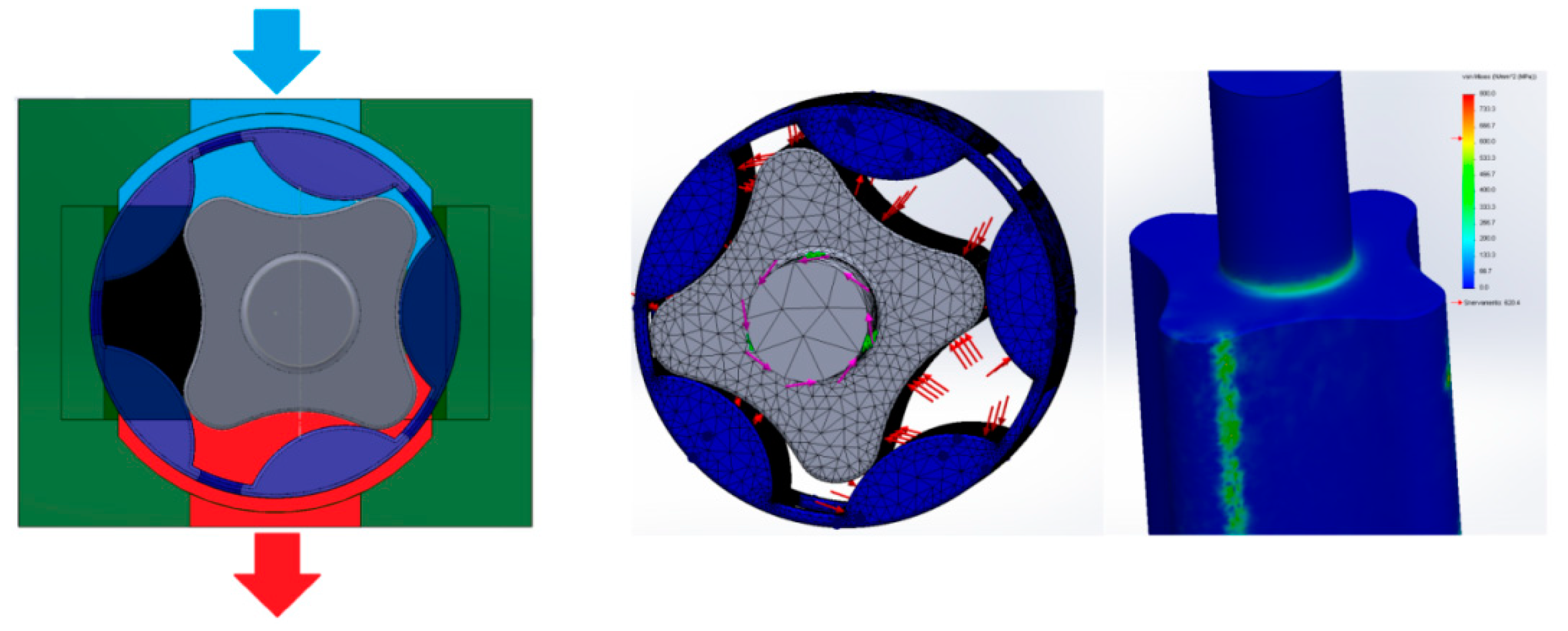
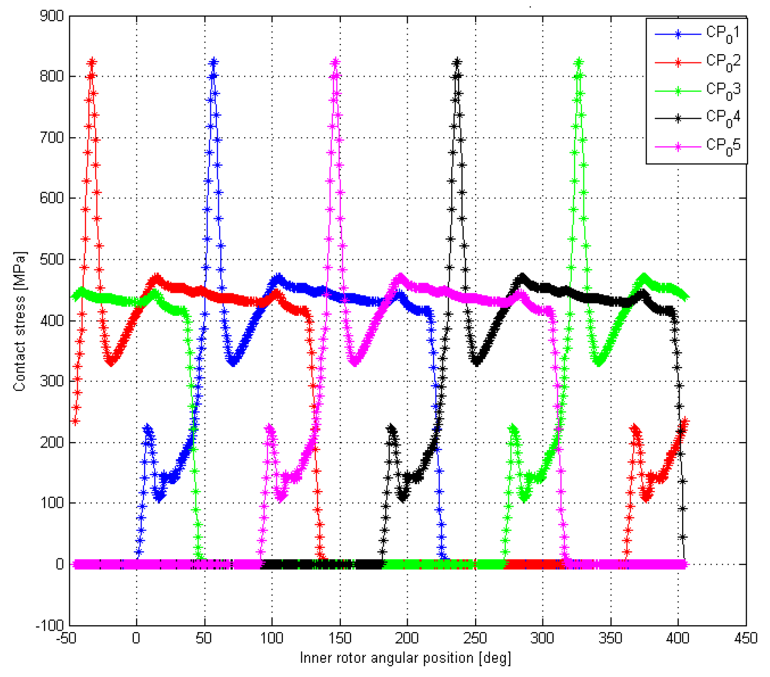
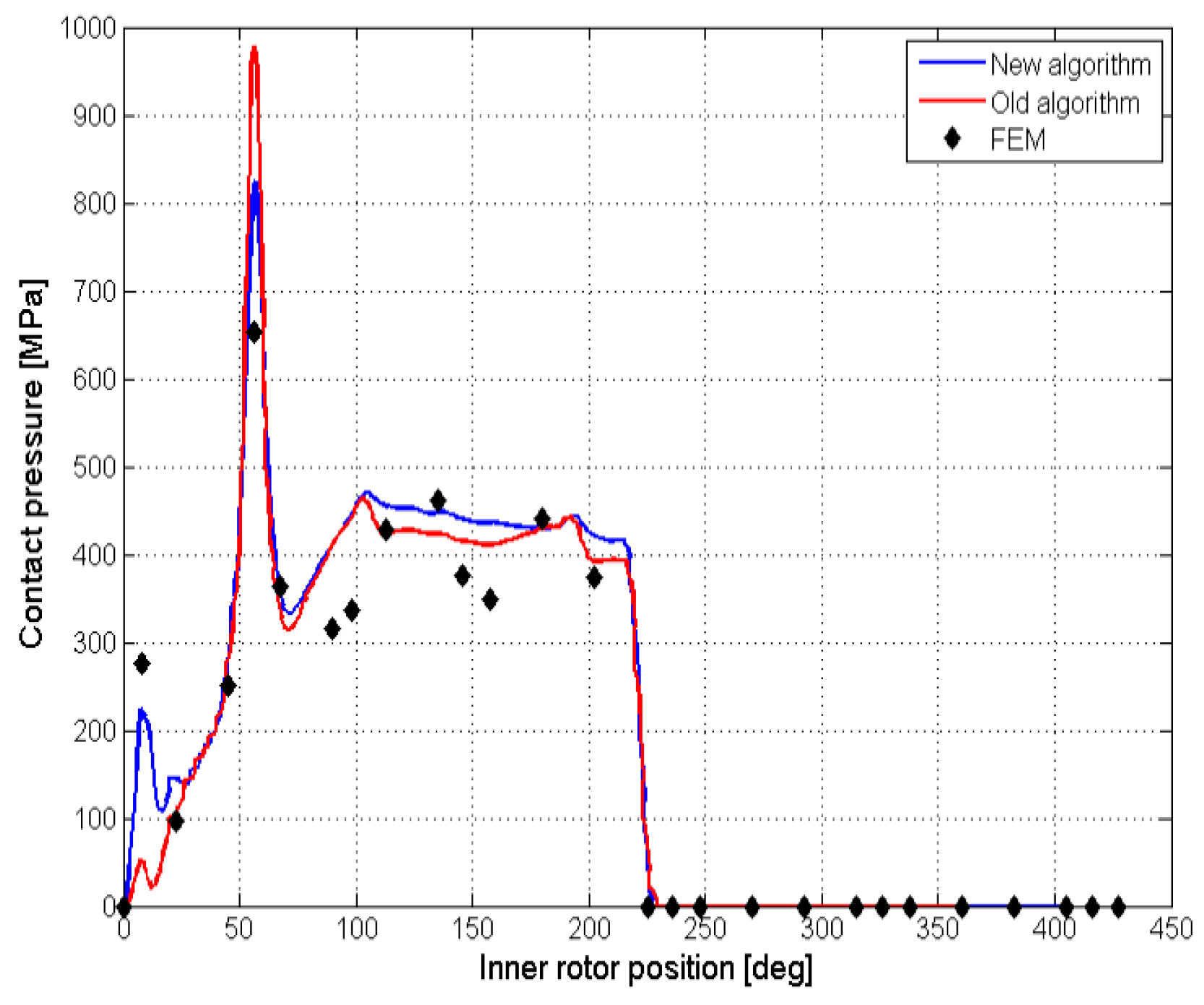
4. Contact Stress Estimation

The determination of the contact stresses in the rotor profiles is made difficult by several factors related to the nature of the meshing process and the presence of the pumped fluid. The first issue is represented by the number of contact zones, which is variable inside of one pump cycle, and possibly affected by non-uniform clearance distribution. Moreover, the load repartition is unknown a-priori, from making a direct computation of the contact forces impossible. Further, the lubrication regime is affected by the operating conditions, so that the actual contact pressure distribution is not constant in time. In order to obtain a first-approximation analysis while keeping the computational time to within reasonable limits, an iterative approach that is similar to the one proposed in [46] is applied. The described method is valid for perfectly crafted rotors operating without clearances, and without lubrication in the contact zones. Moreover, the gear supports and the shaft are considered to be infinitely stiff with respect to the rotor teeth: as such, the deformations due to the contact forces are applied only to the gear lobes. These assumptions are expected to cause contact stress overestimation, since the effects of torsional deformations of the shaft are not computed.
Following this approach, force exchange between the mating teeth is supposed to occur only along the suction side of the pump, as shown in Figure 5. Gearing in the portion of the device that is connected to the delivery environment is instead considered to involve only geometric coupling.
The application of a small arbitrary rotation δ ϕ i n to the inner rotor causes interpenetration wi between the teeth of the two gears. According to the Hertz theory [47], it is then possible to determine the contact force vector Fc as:
F c = π H 4 ( 1 ν i n 2 E i n + 1 ν e x t 2 E e x t ) w
where H is the rotor’s axial length, and E and ν are the Young modulus and the Poisson coefficient for the two gears. The vector w = [ w 1 w 2 w N ] T contains the interpenetration distance for each contact point. Its element wi is non-zero only when measured in the active zone. Considering the frictionless contacts, it is possible to express the resistant torque acting on the driving shaft through the contributions of each contact force Fc,i.
T ( ϕ i n ) = i = 1 N d i F c , i s i n γ
Since the overall resistant torque has been computed by the dynamic model through Equation (23), it is then possible to estimate the contact forces Fc,I by the means of an iterative procedure. Given an arbitrary δ ϕ i n , it is in fact possible to compute through passages (25) and (26) the corresponding T ( δ ϕ i n ) . This torque value is hence compared with a reference signal that is obtained through the dynamic model simulation: if the difference falls below a tunable threshold, the results are accepted, and the contact force value is saved. Otherwise, a proper variation is applied to δ ϕ i n , and the procedure is repeated.
The contact pressures for each tooth can hence be evaluated through the classic Hertz theory [47]:
σ i = 2 F c , i π a i H
where the contact area characteristic dimension ai is determined, considering the formulas available in the literature for cylinder-on-cylinder contact:
a i = 4 F c , i ( 1 ν i n 2 E i n + 1 ν e x t 2 E e x t ) π H ( ρ i n t , i + ρ e x t , i )
The external and the internal profile curvatures for the i-th contact point ρ e x t , i and ρ i n t , i can be easily obtained, considering the geometrical properties of the elliptic lobes. The maximum values of contact stress are then compared to the material limit for the static and repeated Hertzian contact. The contact stress estimation method, and the effect of the use of a coupled dynamic model have been verified through FEM analysis, performed on a reference radial port gerotor; the FEM analysis has been performed in Ansys 14.0, making use of more than 250,000 tetrahedal cells; the results convergence was ensured by progressively refining the mesh in correspondence with the contact points, and tracking the behavior of the contact stress. The reference case has been designed for a 1 bar inlet pressure, and with a speed of 5000 rpm for the driving gear.
The pressure of the delivery environment is supposed to be fixed and equal to 39.6 bar, while the geometry parameters used for the example case are e = 3.5   mm and λ = 1.8 ; a simplified render of the pump can be found in Figure 6. The gerotor axial length has been over-imposed as H = 0.4   R e x t . The analysis was performed by using over 200,000 tetrahedral cells while applying several congruent rotations to the inner and outer rotors. For each angular position, the chambers pressure and the input torque were imported from the dynamic model simulation results reported in Figure 7 and Figure 8.
The results of the algorithm are depicted in Figure 9, while a comparison with the FEM analysis for one contact point is reported in Figure 10; the simulation trend was coherent with the FEM data, even though some deviation in the numerical values was noticed. Focusing on the contact pressure behavior, it was possible to notice two major peaks. The first one occurred during the beginning of the gear meshing, and it was due to the change in the sign of the inner rotor curvature; the second peak was due to variations in the number of meshing teeth.

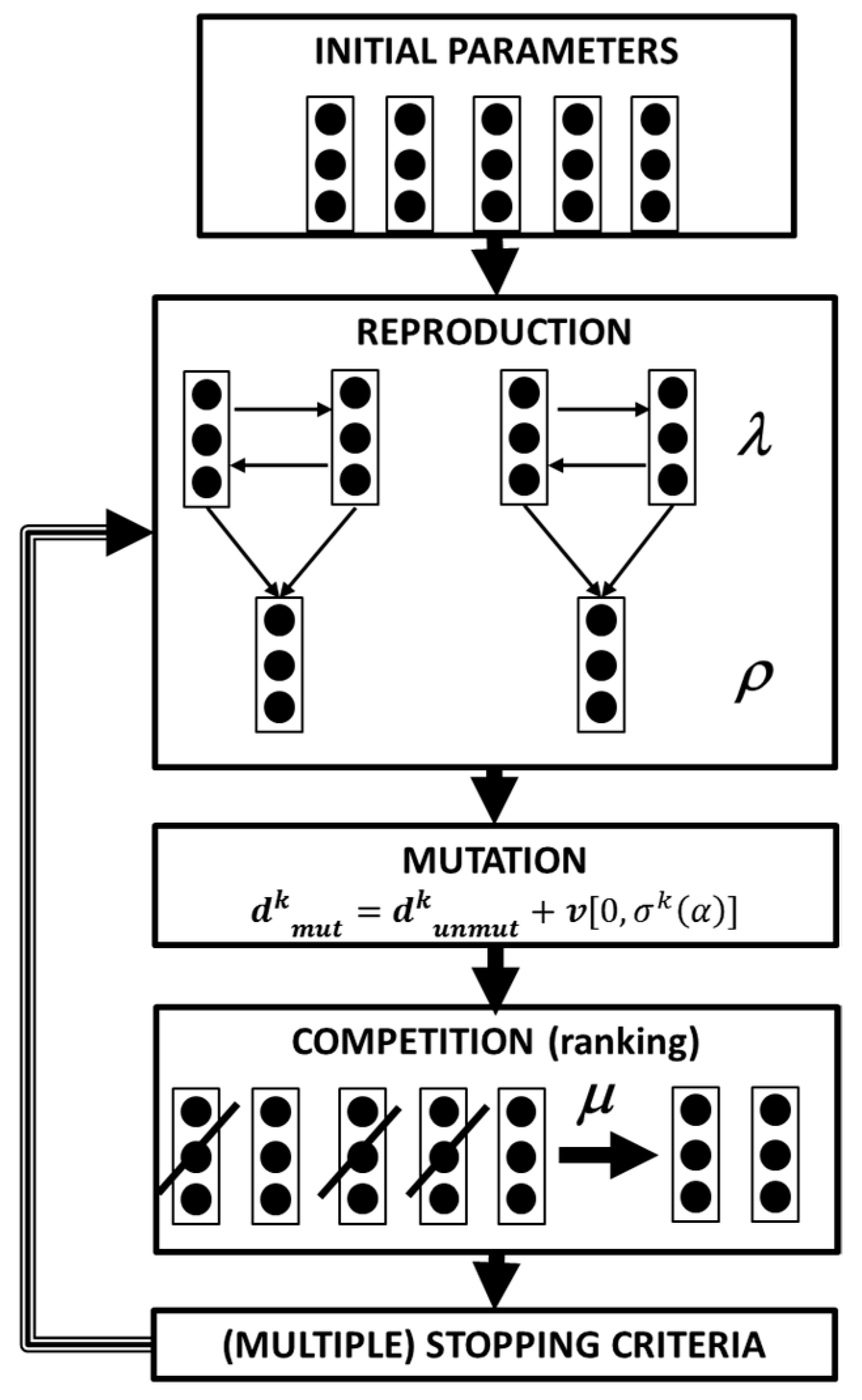
5. Stochastic Optimization Algorithms

Optimization through stochastic algorithm has been widely used over the last few decades to solve engineering problems, whereas it is difficult to provide an a priori hypothesis of the region containing the optimum solution, whereas the objective function is to not continue over its entire dominion [48]. This class of algorithm in fact searches for the optimum application of a certain degree of randomness, and this only revolves around the evaluation of the objective function itself, without the need to compute the function’s gradients. Stochastic methods mainly follow three alternative approaches; genetic algorithms [49], and evolutionary strategies [50] mimic the evolutionary behavior of nature, while simulated annealing imitates the behavior of cooling fluids [51]. Stochastic algorithms have been already applied to pump stacking optimization in [52], and specifically to gerotor profiles in [53] and [54]. Several declinations of the evolutionary strategy for single-objective optimization are available in the literature [48], but they all share the same philosophy, based on the four base principles of the process of organic evolution: reproduction, mutation, competition, and selection [55]. A flow-chart for the most general method, the ( μ / ρ ; λ ) strategy, is reported in Figure 11 [56].
Starting from an initial population, l elements are chosen as the parents, giving birth to r offspring; the simplest method to perform this step is through arithmetical crossover; that is, a linear combination of the vectors containing the optimization parameters of the parents [57]. For a two parents–two offspring scenario, this can be translated as:
{ d u n m u t 1 k + 1 = α d p 1 k + ( 1 α ) d p 2 k d u n m u t 2 k + 1 = α d p 2 k + ( 1 α ) d p 1 k
where d u n m u t 1 k + 1 and d u n m u t 2 k + 1 are the offspring’s parameter vectors, d p 1 k and d p 2 k are the parents, and α is the crossover operator. The offspring are hence mutated by applying a random factor chosen from a standard distribution v centered in 0 with standard deviation σ(α), which is divided or multiplied by a factor α at the beginning of each iteration [52]:
d m u t k + 1 = d u n m u t k + 1 + v [ 0 , σ ( α ) ]
The population, this paper is comprehensive also for the parents, and is hence ranked, and the first μ elements are selected, while the others are discarded. Multiple stopping criteria are finally inserted to put a stop to the optimization loop. In this paper, four alternatives are considered: if one of them is met, the results exits the loop. The first one, is related to the algorithm convergence, and computed through the quadratic norm of the population, with respect to its mean value, as reported in [58]. The second criterion is the number of consecutive loops in which the variation of the optimization parameters remains under a certain threshold. This is due to the fact that each parameter considered is a geometrical quantity that is used to describe a physical object; as such, variations that remains below the geometrical tolerances of the possible production process are not useful. If this condition repeats itself on each parameter for more than three cycles, the algorithm stops the loop. The last condition, related to the computational time required, is the maximum number of iterations.
Evolutionary strategies can be extended to multi-objective optimization by slightly modifying the flowchart that is reported in Figure 11, and paying particular care towards the competition step [59]. Several methods are reported in the literature [60,61,62,63,64,65,66,67,68,69,70,71,72]. In this paper, the fitness r of each possible solution to the optimization problem is defined by using the Fonseca version [61] of the Goldberg criterion, based on the number of dominating solutions [73]:
r ( d i , K ) = 1 + n q ( d i , K )
where n q ( d i , K ) is the number of solutions dominating d i during the K-th generation. One of the most significant difficulties in multi-objective optimization is to avoid the formation of clustered solutions, which causes the overrepresentation of parts of the variables space at the expense of the rest of the dominion, and which may provide misleading results. To limit this issue, the fitness-sharing approach proposed by Fonseca and Fleming [61] has been employed in this paper. This method is based on the computation of the Euclidean distance DK between every solution pair ( d i , d j ) in the objective space, normalized between 0 and 1 during the K-th iteration of the optimization algorithm [61]:
D K ( d i , d j ) = m = 1 n o ( f m K ( d i ) f m K ( d j ) m a x k = 1 K f m m i n k = 1 K f m ) 2
Hence, given those distances, the number of solutions falling inside a niche of size σ n i c h e may be calculated as:
n c ( d i , K ) = j = 1 ( ρ + λ ) r ( d i ) = r ( d j ) m a x ( σ n i c h e D K ( d i , d j ) σ n i c h e , 0 )
Finally, the fitness r ( d i , K ) of each solution for the K-th generation is adjusted as follows [61]:
r ( d i , K ) = r ( d i , K ) n c ( d i , K )
In this way, the overall ranking of the clustered solution in the minimization process is penalized, hence reducing the probability of being selected for breeding, while enhancing the exploration of the optimization parameter space.
We approached the optimization issue as a two-step multi-objective optimization, to highlight the benefits that are associated with the use of asymmetric profiles in obtaining better results than the optimum performances provided by the traditional geometry. Other approaches to the optimization problems can be found in [62,63]; in particular, the authors in [62] used the Taniguchi method to find the optimal combination of parameters to maximize the pumps’ flow rate, and to minimize the flow rate irregularity. Although it is functional for simple optimization problems, the Taniguchi method is mostly used to evaluate the robustness of a proposed design, by studying the influence of small variations of one or more design parameters over the system performances.

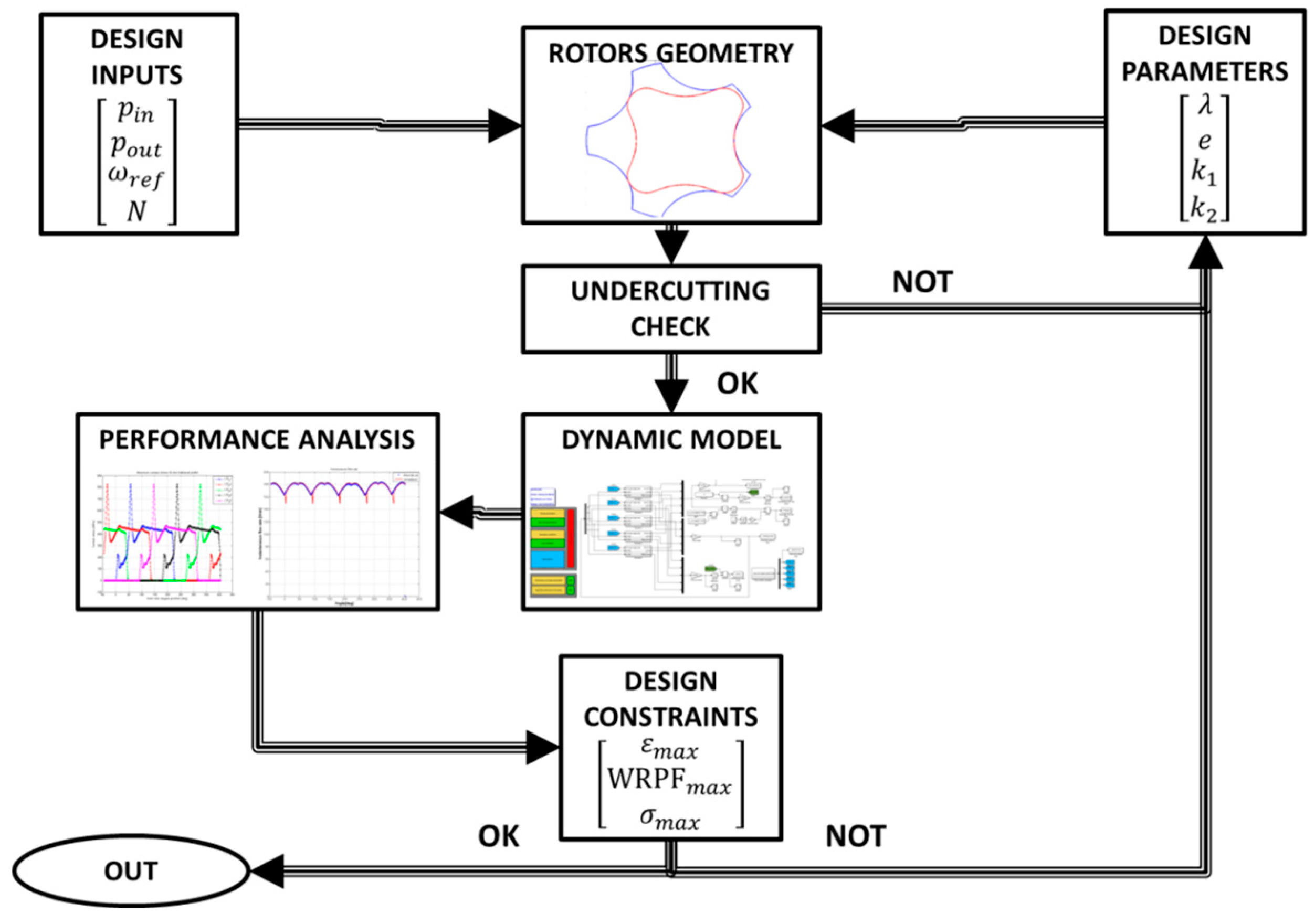
6. Profile Optimization

According to previous sections, we can identify a few optimization parameters that are meaningful geometrical quantities that determine the rotor shape and performance. The optimization process has been carried on for gerotors with five teeth in the external gear, since this solution allows for higher flow rate capabilities at a given reference speed to be obtained [40]. To account for asymmetric teeth based on the union of elliptic arcs, Equation (4) is modified as follows:
{ t a n ( ϑ ) = k t a n ( ξ ) k = k 1 0 ξ π 2 k = k 2 π 2 ξ π
Introducing the non-dimensional design parameter λ = a / r e x t , a generic optimization parameter vector d can be defined as:
d = [ λ e k 1 k 2 ]
Three indexes are used to evaluate the pump performance, and to perform the optimization procedure: the flow rate irregularity ε , the wear Rate proportional factor (WRPF) and the estimated rotors mass m. The flow rate irregularity is used to measure the flow ripples produced due to the discontinuity in the fluid delivery. It is commonly expressed as the ratio between the ripples’ amplitude and the average flow rate Qm, given a constant reference speed of the driving gear [74]:
ε = m a x ( Q ) m i n ( Q ) Q m
The wear rate proportional factor proposed by Kwon [75] is used to rank the wear rate under the hypothesis of a non-lubricated contact, and is defined as follows:
W R P F = σ i v s ω i n
where σ i is the contact stress, v s is the relative speed between the two rotors in the contact point, and ω i n the reference speed of the inner gear. The rotors mass estimate is provided by multiplying the gear volume for the employed material density. For each parameter vector, the corresponding gerotor pump is designed and tested through an integrated framework, employing the equations presented in the previous sections. Its flowchart is reported in Figure 12: starting from the design inputs fixed for the optimization process and the geometrical parameters vector, the rotor profiles are defined, verified, and inserted into the high-fidelity dynamic model of the pump. The simulation outputs are hence used to compute the pump’s performance indexes; the design loop is eventually reset if one or more geometrical constraints or performance requirements are not met.

6.1. Cycloidal Gears Optimization

The first step for assessing the capabilities of the asymmetric profile is to define a proper set of reference values for each of the three optimization objectives. In order to do so, three series of single-objective optimization cycles have been performed for the traditional ephitrocoidal profiles. The reference speed of the driving rotor has been varied to between 5000 rpm and 10,000 rpm, to target a mobile application, while the pressure at the inlet port is approximately 1 bar. The required flow rate has been set to 100 L/min. For each reference speed, the pump geometry has been optimized with respect to each performance index, leading to the definition of three sets of gerotor profiles, each able to minimize the flow irregularity, wear rate, and rotor mass. The optimization parameters vector is obtained, simplifying the one that is reported in Equation (21), by neglecting k1 and k2. Starting from these parameters, the algorithm designs and tests the gerotor through the automatic framework. The safety factor against cavitation is initially set to 1.
The number of parents in the evolutionary algorithm is set to λ o p t = 4 , while the offsprings are ρ o p t = 6 . The population size that survives after each optimization cycles is μ o p t = 8 . In order to achieve a faster convergence, the parents are not discarded a-priori, and they take part in the ranking; as such, it is possible for them to survive for more than one optimization cycle. To monitor the algorithm behavior, the ratio of successful mutation for the k-th optimization cycle has been computed as:
p m k = | D ρ k D μ k | | D μ k |
where D ρ and D μ are respectively, the sets of the mutated offspring, and of the population that survives after the k-th cycle. The maximum number of iterations allowed for the algorithm is Nmax = 50. The results of the optimization process are reported in Figure 13. The wear rate and rotor masses tend to progressively decrease, with the reference speed tending to reach a plateau towards the end of the investigated speed range. This can be explained by considering that the flow rate requirement remains the same for the whole speed range; as such, the benefits of downsizing the gerotor radial dimension are progressively decreased by the increase in the pump length. For the same reason, no appreciable variation of the optimum flow rate irregularity can be observed.
A comprehensive description of the λ—e couple for each case is provided in Figure 14a, while the corresponding rotors geometries are reported in Figure 15. In particular, some interesting considerations may be performed: it can be noted how the rotor mass minimization makes use of the highest value of eccentricity and the lowest λ parameters, while the opposite happens for the flow irregularity. The wear optimization finds itself in the middle of the other two cases. From the perspective of a multi-objective optimization, this seems to suggest that the minimization of the (ε; WRPF) and (mass; WRPF) couples may be obtained more easily than that of the (ε; mass) one.
Looking at Figure 14b, it is possible to notice the immediate consequences of the different ( λ , e ) sets. The profiles that optimize the rotors mass presented higher teeth, hence generating chambers with higher frontal areas and shorter pumps. On the other side, geometries optimizing the flow-rate irregularities featured small teeth that are able to provide a more regular flow rate output at the expense of longer, and hence, heavier devices. Looking at the profiles depicted in Figure 15, it is possible to notice how their shapes seem to be almost independent of the reference speed, and only change with the function of the optimization objective. An explanation for this behavior can be provided by looking at Figure 14a, and noticing that the eccentricity of the optimized profiles tend to decrease linearly with speed.
From Equation (14), it is known that the radial size of the gerotor pump is inversely proportional to the speed of the driving gear; hence, the ratio between the eccentricity of each optimum solution and the radial size of the device should be constant, given the inlet pressure, fluid properties, and optimization objectives. The related results for the studied profiles are presented in Figure 16.

6.2. Second-Order Optimization through Asymmetric Lobes

The asymmetric lobe design could also be used as a second-order optimization on an optimized circular lobe profile. In this situation, the optimization parameter d is reduced to:
d = [ k 1 k 2 ]
while the ( λ , e ) couple is determined by the optimization of the traditional profile. The second-order optimization was been performed over the combined behavior of the flow rate irregularity, rotor masses, and WRPF. The optimized parameters are reported in Table 1.
The second-order optimization, as shown in Figure 17 and Figure 18, allows for noticeable advantages on the performance indexes to be achieved. Starting from the couple optimized for the flow rate irregularity, the use of asymmetric teeth allows a significant reduction in the rotor masses (−5.68%) to be obtained, while the expected flow-rate irregularity (+0.29%) and wear rate (+0.03%) remain almost constant. In a similar fashion, the second-order optimization allows some advantages to be obtained when applied to the WRPF-optimized profiles, achieving a small reduction in the expected (−0.66%), wear rate (−1.31%) and rotor mass (−0.24%).
More significant are the results that are related to the second-order optimization of the traditional profiles that are first optimized with respect to the estimated mass. In this case, the use of asymmetric teeth allows for an average decrease of the flow irregularity, computed as 1.40%, to be obtained, while the estimated rotors mass sees an average variation that is equal to −3.23%; more importantly, a significant decrease (−14.61%) can be appreciated in the estimated wear rate. An example of the second-order optimization effects over the pumps’ geometry is reported in Figure 19.

7. Discussion and Further Work

The optimization activities described in this paper have proven that asymmetric lobes are able to provide several advantages over the traditional profile for gerotor pumps operating in the same direction for the most part of their operative life. At first, the theory and the design framework implemented in this work have been presented and discussed, and hence used inside the optimization loops. The proposed optimization procedure consists of two steps; the first one being the optimization of the traditional profile to define the lobe sizes along the radial direction, and hence applying a second-order procedure to optimize the lobe shapes. Following this procedure, the half-side of the teeth involved in significant force exchange is optimized, to minimize the estimated wear rate, while the other half is modified to reduce the predicted mass and flow irregularity. It has been proven that through the use of asymmetric lobes, it is possible to obtain better performances over each of the considered performance indexes, with respect to the optimum that is obtainable for the traditional cycloidal profile. In particular, the results suggest marked performance improvements for those mobile applications where weight reduction is the most significant issue, such as the aerospace field, where gerotor pumps can be used in the lubrication systems of the aircraft engines. Further work will include a comparison between the different shapes of the two half-lobes, and eventually applications towards multi-curve geometries.

Author Contributions

The work presented in this paper has been performed by A.D.M. under the supervision of G.J. and M.S.

Funding

This research received no external funding.

Acknowledgments

The work presented in this paper has been performed within the research programme “Greening the Propulsion”, which is funded by the Italian Government, and led by GE AvioAero. The authors would like to thank eng. Andrea Casetti for the valuable and experienced help that he provided during this project.

Conflicts of Interest

The funders had no role in the design of the study; in the collection, analyses, or interpretation of data; in the writing of the manuscript, or in the decision to publish the results.

Nomenclature

α Crossover operator
β Fluid bulk modulus
α Angular pitch
ε Flow rate irregularity
ξ Angular parameter for a parametric description of the lobe geometry
γ Angle between the normal to the contact point and the radial direction
Γ e x t External gear profile in its integral reference system
Γ e x t i n External gear profile in the inner gear reference system
Γ i n Inner gear profile in its integral reference system
ϕ e x t Angular position of the external gear
ϕ i n Angular position of the inner gear
λ Non-dimensional design parameter
λ o p t Number of parents in the evolutionary algorithm
μ Fluid dynamic viscosity
μ o p t Number of surviving elements at each iteration of the evolutionary algorithm
ν Poisson ratio
ψ Profile parameterization
ρ Fluid density
ρ e x t , i Curvature of the external profile
ρ i n t , i Curvature of the internal profile
ρ o p t Number of offspring in the evolutionary algorithm
ρ χ Local radius of the lobe
ϑ Angular coordinates for lobe geometry description
σ i Contact stress
τ i e Transmission ratio between the gears
ω e x t Angular speed of the external gear
ω i n Angular speed of the inner gear
χ Profile parameterization
A c h Frontal area of the chamber
A p Port area
A r Required port area
a i Characteristic dimensions of the contact area
C Center of the lobe profile
C d Discharge coefficient
d i Distance between the gerotor axis and the contact points
d p k “Parent” parameter vector belonging to the k-th generation
d u n m u t k + 1 Parameter vector for the k+1 generation before mutation
E Young’s modulus
e Gerotor eccentricity
F c Contact force
k Elliptic parameter
k s Safety coefficient against cavitation
h g Height of the leakage path
H Axial length of the chambers
l g Length of the leakage path
M i n , e x t Transformation matrix
N Tooth number of the external gear
N e x t Normal to the external gear profile
O e x t Center of the external gear centrode
O i n Center of the inner gear centrode
p i Mean pressure inside the i-th chamber
p i n Pressure at the inlet port
p P Pressure at the port
p v Vapor tension
Q Pump total flow rate
Q i Net flow rate for the i-th chamber
Q i 1 , i Flow rate between the i-1th and i − 1th chambers
Q m Average pump flow rate
Q p , i Flow rate from the port to the i-th variable volume chamber
r Fitness of the optimization problem solution
r e x t Radius of the external gear centrode
r i n Radius of the internal gear centrode
r l i m , e x t Limit value of the external gear radius
r l i m , i n Limit value of the inner gear radius
r k Position of the generic point k in the lobe reference system
T Driving torque
V i Volume of the i-th chamber
v l i m Limit speed
v s Sliding speed between mating profiles
w Co-penetration between gears profiles
WRPFWear rate proportional factor
( x , y ) e x t Reference frame integral with the external gear
( x , y ) f Fixed reference frame
( x , y ) i n Reference frame integral with the inner gear

References

  1. Mancò, G.; Mancò, S.; Rundo, M.; Nervegna, N. Computerized generation of novel gearings for internal combustion engines lubricating pumps. Int. J. Fluid Power 2000, 1, 49–58. [Google Scholar] [CrossRef]
  2. Meyr, N.; Cardé, C.; Nitta, C.; Garas, D.; Garrard, T.; Parks, J.; Vaughn, J.; Bangar, C.; Francisco, A.; Duvall, M.; et al. Design and Development of the 2002 UC Davis Future Truck; SAE Technical Paper; SAE International: Warrendale, PA, USA, 2002. [Google Scholar]
  3. Ippoliti, L.; Hendrick, P. Influence of the supply circuit on oil pump performance in an aircraft engine lubrication system. In Proceedings of the ASME Turbo Expo 2013: Turbine Technical Conference and Exposition, San Antonio, TX, USA, 3–7 June 2013. [Google Scholar]
  4. Frosina, E.; Senatore, A.; Buono, D.; Manganelli, M.U.; Olivetti, M. A tridimensional CFD analysis of the oil pump of an high performance motorbike engine. Energy Procedia 2014, 45, 938–948. [Google Scholar] [CrossRef]
  5. Colbourne, J.R. The geometry of trochoid envelopes and their applications in rotary pumps. Mech. Mach. Theory 1974, 9, 421–435. [Google Scholar] [CrossRef]
  6. Beard, J.E.; Hall, A.S.; Soedel, W. Comparison of hypotrochoidal and epitrochoidal gerotors. J. Mech. Des. 1991, 113, 133–141. [Google Scholar] [CrossRef]
  7. Beard, J.E.; Yannitell, D.W.; Pennock, G.R. The effects of the generating pin size and placement on the curvature and displacement of epitrochoidal gerotors. Mech. Mach. Theory 1992, 27, 373–389. [Google Scholar] [CrossRef]
  8. Adams, G.; Beard, J.E. Comparison of helical and skewed axis gerotor pumps. Mech. Mach. Theory 1997, 32, 729–742. [Google Scholar] [CrossRef]
  9. Shung, J.B.; Pennock, G.R. Geometry for trochoidal-type machines with conjugate envelopes. Mech. Mach. Theory 1994, 29, 25–42. [Google Scholar] [CrossRef]
  10. Litivn, F.L. Theory of Gearing; NASA: Washington, DC, USA, 1989.
  11. Litvin, F.L.; Feng, P.-H. Computerized design and generation of cycloidal gearings. Mech. Mach. Theory 1996, 31, 891–911. [Google Scholar] [CrossRef]
  12. Vecchiato, D.; Demenego, A.; Argyris, J.; Litvin, F.L. Geometry of a cycloidal pump. Comput. Methods Appl. Mech. Eng. 2001, 190, 2309–2330. [Google Scholar] [CrossRef]
  13. Hwang, Y.-W.; Hsieh, C.-F. Determination of surface singularities of a cycloidal gear drive with inner meshing. Math. Comput. Model. 2007, 45, 340–354. [Google Scholar] [CrossRef]
  14. Mimmi, G.; Pennacchi, P. Non-undercutting conditions in internal gears. Mech. Mach. Theory 2000, 35, 477–490. [Google Scholar] [CrossRef]
  15. Ivanovic, L.; Jositovic, D. Specific sliding of trochoidal gearing profile in the gerotor pumps. FME Trans. 2006, 34, 121–127. [Google Scholar]
  16. Ivanovic, L.; Devedzic, G.; Cukovic, S.; Miric, N. Modeling of the meshing of trochoidal profiles with clearances. J. Mech. Des. 2012, 134, 041003. [Google Scholar] [CrossRef]
  17. Ivanovic, L.; Devedzic, G.; Miric, N.; Cukovic, S. Analysis of forces and moments in gerotor pumps. Proc. Inst. Mech. Eng. Part C JMES 2010, 224, 2257–2269. [Google Scholar] [CrossRef]
  18. Hsieh, C.F. Influence of gerotor performance in varied geometrical design parameters. J. Mech. Des. 2009, 131, 121008. [Google Scholar] [CrossRef]
  19. Hsieh, C.F. Fluid and dynamic analyses of a gerotor pump using various span angle designs. J. Mech. Des. 2012, 134, 121003. [Google Scholar] [CrossRef]
  20. Hsieh, C.F.; Hwang, Y.W. Geometric design for a gerotor pump with high area efficiency. J. Mech. Des. 2007, 129, 1269–1277. [Google Scholar] [CrossRef]
  21. Mimmi, G.; Pennacchi, P. Rotor design and optimization in internal lobe pumps. Appl. Mech. Rev. 1997, 50, 133–141. [Google Scholar] [CrossRef]
  22. Bonandrini, G.; Mimmi, G.; Rottenbacher, C. Theoretical analysis of an original rotary machine. J. Mech. Des. 2010, 132, 024501. [Google Scholar] [CrossRef]
  23. Bonandrini, G.; Mimmi, G.; Rottenbacher, C. Design and simulation of meshing of a particular internal rotary pump. Mech. Mach. Theory 2012, 49, 104–116. [Google Scholar] [CrossRef]
  24. Demenego, D.A.; Vecchiato, F.L.; Litvin, N.; Nervegna, S.; Mancò, S. Design and simulation of meshing of a cycloidal pump. Mech. Mach. Theory 2002, 37, 311–332. [Google Scholar] [CrossRef]
  25. Chiu-Fan, H. Flow characteristics of gerotor pumps with novel variable clearance design. ASME J. Fluids Eng. 2015, 137, 041107. [Google Scholar]
  26. Shih-His, T.; Yan, J.; Yang, D.C.H. Design of deviation-function based gerotors. Mech. Mach. Theory 2009, 44, 1595–1606. [Google Scholar]
  27. Yang, D.C.H.; Yan, J.; Shih-Hsih, T. Flowrate formulation of deviation function based gerotor pumps. J. Mech. Des. 2010, 132, 064503. [Google Scholar] [CrossRef]
  28. Yan, J.; Yang, D.C.; Shih-Hsih, T. On the generation of analytical noncircular multilobe internal pitch curves. J. Mech. Des. 2009, 130, 092601. [Google Scholar] [CrossRef]
  29. Litvin, F.L.; Demenego, A.; Vecchiato, D. Formation by branches of envelope to parametric families of surfaces and curves. Comput. Methods Appl. Mech. Eng. 2001, 190, 4587–4608. [Google Scholar] [CrossRef]
  30. Yan, J.; Shih-Hsih, T.; Yang, D.C.H. A new gerotor design method with switch angle assignability. In Proceedings of the 10th ASME International Power Transmission and Gearing Conference, Las Vegas, NV, USA, 4–7 September 2007. [Google Scholar]
  31. Choi, T.H.; Kim, M.S.; Lee, G.S.; Yung, S.Y.; Bae, J.H.; Kim, C. Design of rotor for internal gear pump using cycloid and circular-arc curves. J. Mech. Des. 2012, 134, 011005. [Google Scholar] [CrossRef]
  32. Bae, J.H.; Kwak, H.S.; San, S.; Kim, C. Design and CFD analysis of gerotor with multiple profiles (ellipse-involute-ellipse type and 3-ellipses type) using rotation and translation algorithm. Proc. Inst. Mech. Eng. Part C JMES 2015, 230, 804–823. [Google Scholar] [CrossRef]
  33. Jung, S.Y.; Bae, J.H.; Kim, M.S.; Kim, C. Development of new gerotor for oil pumps with multiple profiles. Int. J. Precis. Eng. Manuf. 2011, 12, 835–841. [Google Scholar] [CrossRef]
  34. Lizhen, H. Tooth profiles analysis for internal pump gear with straight line-conjugate curve profile. J. Mech. Transm. 2004, 6, 16–18. [Google Scholar]
  35. Xu, X.; Song, T.L. Optimization design of internal gear pump with straight line conjugate curve profile. J. Mech. Transm. 2007, 4, 69–71. [Google Scholar]
  36. Xu, X.Z.; Song, T.L. Analysis of flow characteristics of gear pump with straight line profile. Coal Mine Mach. 2008, 7, 47–49. [Google Scholar]
  37. Rundo, M. Models for Flow Rate Simulation in Gear Pumps: A review. Energy 2017, 10, 1261. [Google Scholar] [CrossRef]
  38. Gamez-Montero, P.J.; Castilla, R.; Codina, E.; Freire, J.; Morató, J.; Sanchez-Casas, E.; Flotats, I. GeroMAG: In-House Prototype of an Innovative Sealed, Compact and Non-Shaft-Driven Gerotor Pump with Magnetically-Driving Outer Rotor. Energy 2017, 10, 435. [Google Scholar] [CrossRef]
  39. Mancò, S.; Nervegna, N.; Rundo, M. Critical issues on performance of lubricating gerotor pumps at high rotational speed. In Proceedings of the 7th Scandinavian International Conference on Fluid Power, Linköping, Sweden, 30 May–1 June 2001; pp. 23–38. [Google Scholar]
  40. Jacazio, G.; De Martin, A. Influence of rotor profile geometry on the performance of an original low-pressure gerotor pump. Mech. Mach. Theory 2016, 100, 296–312. [Google Scholar] [CrossRef]
  41. Franc, J.-P. Physics and Control of Cavitation, Chapter in Design and Analysis of High Speed Pumps; NATO RTO Educational Notes; NATO: Washington, DC, USA, 2006. [Google Scholar]
  42. Singh, T. Design of Vane Pump Suction Porting to Reduce Cavitation at High Operation Speeds; SAE Technical Paper; SAE International: Warrendale, PA, USA, 1991. [Google Scholar]
  43. Idel’Chik, I.E. Handbook of Hydraulic Resistance, 3rd ed.; Jaico: Mumbai, India, 2008. [Google Scholar]
  44. Viersma, T.J. Analysis, Synthesis and Design of Hydraulic Servosystems and Pipelines; Elsevier: Amsterdam, The Netherlands, 1980. [Google Scholar]
  45. Jelali, M.; Kroll, A. Hydraulic Servo-Systems; Springer: Berlin, Germany, 2003. [Google Scholar]
  46. Gamez-Montero, P.J.; Castilla, R.; Khamashta, M.; Codina, E. Contact problems of a trochoidal-gear pump. Int. J. Mech. Sci. 2006, 48, 1471–1480. [Google Scholar] [CrossRef]
  47. Johnson, K.L. Contact Mechanics; Cambridge University Press: Cambridge, UK, 1985. [Google Scholar]
  48. Alotto, P.G.; Eranda, C.; Brandtatter, B.; Furnrtratt, G.; Magele, C.; Molinari, G.; Nervi, M.; Preis, K.; Repetto, M.; Richter, K. Stochastic Algorithms in Electromagnetic Optimization. IEEE Trans. Magn. 1998, 34, 3674–3684. [Google Scholar] [CrossRef]
  49. Rechenberg, I. Evolutionsstrategie 94; Frommann-Holzboog: Stuttgart, Germany, 1994. [Google Scholar]
  50. Holland, J.H. Adaption in Natural and Artificial Systems; MIT Press: Cambridge, MA, USA, 1992. [Google Scholar]
  51. Metropolis, N.; Rosenbluth, A.W.; Rosenbluth, M.N.; Teller, A.H.; Teller, E. Equation of state calculations by fast computing machines. J. Chem. Phys. 1955, 21, 1087–1092. [Google Scholar] [CrossRef]
  52. Kelner, V.; Léonard, O. Application of genetic algorithms to lubrication pump stacking design. J. Comput. Appl. Math. 2004, 168, 255–265. [Google Scholar] [CrossRef] [Green Version]
  53. Kim, J.H.; Kim, C.; Chang, Y.J. Optimum design on lobe shapes of gerotor oil pump. J. Mech. Sci. Technol. 2006, 20, 1390–1398. [Google Scholar] [CrossRef]
  54. Kwon, S.; Kim, C.; Shin, J. Optimal rotor wear design in hypotrochoidal gear pump using genetic algorithm. J. Cent. South Univ. Technol. 2011, 18, 718–725. [Google Scholar] [CrossRef]
  55. Fogel, D.B. Evolutionary Computation; IEEE Press: New York, NY, USA, 1995. [Google Scholar]
  56. Schwefel, H.P. Numerische Optimierung von Computer-Modellen Mittels der Evolutionsstrategie; Birkhaeuser: Basel, Switzerland, 1977. [Google Scholar]
  57. Janikow, C.J.; Michalewicz, Z. An experimental comparison of binary and floating point representation in genetic algorithms. In Proceedings of the 4th International Conference Genetic Algorithms, Los Altos, CA, USA, 13–16 July 1991; pp. 31–36. [Google Scholar]
  58. Back, T.; Schwefel, H.P. An Overview of Evolutionary Algorithms for Parameter Optimization, Evolutionary Computation; MIT Press: Cambridge, MA, USA, 1993. [Google Scholar]
  59. Konak, A.; Coit, D.W.; Smith, A.E. Multi-objective optimization using genetic algorithms: A tutorial. Reliab. Eng. Syst. Saf. 2006, 91, 992–1007. [Google Scholar] [CrossRef]
  60. Schaffer, J.D. Multiple objective optimization with vector evaluated genetic algorithms. In Proceedings of the International Conference on Genetic Algorithm and Their Applications, Pittsburh, PA, USA, 24–26 July 1985. [Google Scholar]
  61. Fonseca, C.M.; Fleming, P.J. Multiobjective genetic algorithms. In IEE Colloquium on Genetic Algorithms for Control Systems Engineering; IET: London, UK, 1993. [Google Scholar]
  62. Ivanovic, L.; Stojanovic, B.; Blagojevic, J.; Bogdanovic, G.; Marinkovic, A. Analysis of the flow rate and the volumetric efficiency of the trochoidal pump by application of Taguchi method. Tehnički Vjesnik 2017, 24, 265–270. [Google Scholar]
  63. Robinson, A.; Vacca, A. Multi-objective optimization of circular-toothed gerotors for kinematics and wear by genetic algorithm. Mech. Mach. Theory 2018, 128, 150–168. [Google Scholar] [CrossRef]
  64. Horn, J.; Nafpliotis, N.; Goldberg, D.E. A niched Pareto genetic algorithm for multiobjective optimization. In Proceedings of the First IEEE Conference on Evolutionary Computation. IEEE World Congress on Computational Intelligence, Orlando, FL, USA, 27–29 June 1994. [Google Scholar]
  65. Hajela, P.; Lin, C.-Y. Genetic search strategies in multicriterion optimal design. Struct. Optim. 1992, 4, 99–107. [Google Scholar] [CrossRef]
  66. Murata, T.; Ishibuchi, H. MOGA, multi-objective genetic algorithms. In Proceedings of the 1995 IEEE International Conference on Evolutionary Computation, Perth, WA, Australia, 29 November–1 December 1995. [Google Scholar]
  67. Srinivas, N.; Deb, K. Multiobjective optimization using nondominated sorting in genetic algorithms. J. Evol. Comput. 1994, 2, 221–248. [Google Scholar] [CrossRef]
  68. Zitzler, E.; Thiele, L. Multiobjective evolutionary algorithms: A comparative case study and the strength Pareto approach. IEEE Trans. Evol. Comput. 1999, 3, 257–271. [Google Scholar] [CrossRef]
  69. Corne, D.W.; Knowles, J.D.; Oates, M.J. The Pareto envelope-based selection algorithm for multiobjective optimization. In Proceedings of the Sixth International Conference on Parallel Problem Solving from Nature, Paris, France, 18–20 September 2000. [Google Scholar]
  70. Lu, H.; Yen, G.G. Rank-density-based multiobjective genetic algorithm and benchmark test function study. IEEE Trans. Evol. Comput. 2003, 7, 325–343. [Google Scholar]
  71. Yen, G.G.; Lu, H. Dynamic multiobjective evolutionary algorithm: Adaptive cell-based rank and density estimation. IEEE Trans. Evol. Comput. 2003, 7, 253–274. [Google Scholar] [CrossRef]
  72. Deb, K.; Agrawal, S.; Pratap, A.; Meyarivan, T. A fast elitist nondominated sorting genetic algorithm for multi-objective optimization: NSGA-II. In Proceedings of the Sixth International Conference on Parallel Problem Solving from Nature, Paris, France, 18–20 September 2000. [Google Scholar]
  73. Goldberg, D.E. Genetic Algorithms in Search, Optimization, and Machine Learning; Addison-Wesley: Reading, MA, USA, 1989. [Google Scholar]
  74. Karamooz Ravari, M.R.; Forouzan, M.R.; Moosavi, H. Flow irregularity and wear optimization in epitrochoidal gerotor pumps. Meccanica 2012, 47, 9178–9928. [Google Scholar]
  75. Kwon, S.-M.; Kim, M.S.; Shin, J.-H. Analytical wear model of a gerotor pump without hydrodynamic effect. J. Adv. Mech. Des. Syst. Manuf. 2008, 2, 230–237. [Google Scholar] [CrossRef]
Figure 1. Gerotor pump scheme.
Machines 07 00017 g001
Figure 2. Reference systems for gerotor design.
Machines 07 00017 g002
Figure 3. Gerotor profile generation.
Machines 07 00017 g003
Figure 4. Flow rates balance for i-th chamber.
Machines 07 00017 g004
Figure 5. Geometrical quantities for contact force evaluation.
Machines 07 00017 g005
Figure 6. Reference gerotor render, mesh, and FEM result examples.
Machines 07 00017 g006
Figure 7. Oil pressure inside the chambers.
Machines 07 00017 g007
Figure 8. Resistant torque.
Machines 07 00017 g008
Figure 9. Contact pressures (algorithm).
Machines 07 00017 g009
Figure 10. Contact pressures: algorithm vs FEM.
Machines 07 00017 g010
Figure 11. Flowchart for the ( μ / ρ ; λ ) strategy.
Machines 07 00017 g011
Figure 12. Design framework flowchart.
Machines 07 00017 g012
Figure 13. Cycloidal profile—single objective optimization results.
Machines 07 00017 g013
Figure 14. Optimized cycloidal profiles. (a) Geometrical parameters (b) comparison for 5000 rpm.
Machines 07 00017 g014
Figure 15. Optimized cycloidal profiles in the 5000–10,000 rpm range.
Machines 07 00017 g015
Figure 16. e / R e x t ratios for the optimized gerotors.
Machines 07 00017 g016
Figure 17. Second-order optimization: WRPF.
Machines 07 00017 g017
Figure 18. Second-order optimization: mass.
Machines 07 00017 g018
Figure 19. Example of second-order optimization for n = 7000 rpm.
Machines 07 00017 g019
Table 1. Second-order optimization parameters.
Speed (rpm)Objective of the First Optimization Process
( ε ) ( m ) ( WRPF )
λ (-) e (mm) k 1 (-) k 2 (-) λ (mm) e (-) k 1 (-) k 2 (-) λ (mm) e (-) k 1 (mm) k 2 (-)
50002.1183.0740.7201.1591.8205.3260.7471.0702.0633.6430.9391.115
60002.0462.8800.7531.1791.9324.5820.8341.1422.0413.2790.8791.114
70002.0002.3880.7751.0371.8213.8070.7801.0912.0472.6710.8511.099
80002.1621.8290.7431.1791.8623.5370.7651.0282.1262.5580.8051.041
90002.2441.6360.8781.1091.8133.0740.7611.0802.1262.0250.8151.175
10,0002.1591.4860.7571.0162.1102.5250.9131.1032.1682.0140.8591.122

