Article

Weight Minimization of Type 2 Composite Pressure Vessel for Fuel Cell Electric Vehicles Considering Mechanical Safety with Kriging Metamodel

1
Graduate School of Mechanical Engineering, Konkuk University, Seoul 05029, Republic of Korea
2
School of Mechanical Engineering, Konkuk University, Seoul 05029, Republic of Korea
*
Author to whom correspondence should be addressed.
Machines 2024, 12(2), 132; https://doi.org/10.3390/machines12020132
Submission received: 4 December 2023 / Revised: 8 February 2024 / Accepted: 12 February 2024 / Published: 13 February 2024

Abstract

:
In recent years, increased sales of fuel cell electric vehicles (FCEVs) have required composite overwrapped pressure vessel (COPV) designs to be lightweight and allow safe high-pressure hydrogen storage. In this study, we propose the weight minimization of Type 2 COPVs for FCEVs considering mechanical safety. Steel liner thickness, ply thickness, ply orientation, and the number of plies were set as design variables, and weight minimization was performed. For the constraints of optimization, the Tsai–Wu failure index of the composite layer and von Mises stress of the steel liner are considered. The design of experiments (DoE) was conducted to generate kriging model and perform sensitivity analysis. The optimized design of Type 2 COPVs was determined by satisfying all constraints, with significant weight reduction and preserved mechanical safety of the structure.

1. Introduction

Recent environmental requirements have increased sales of fuel cell electric vehicles (FCEVs), which use hydrogen and oxygen as fuel and are operated by a fuel cell system that generates electricity through an electrochemical reaction. Therefore, FCEVs are using pressure vessels that can be recharged and discharged easily to store energy. This is shown in Figure 1. Pressure vessels are hydrogen storage tanks designed to keep hydrogen at high pressure, which can reduce fuel expenses by decreasing the overall weight of the vehicle. However, designing a thin-walled pressure vessel to improve the fuel economy of a hydrogen electric vehicle can lead to mechanical failure. When pressure vessels are filled with hydrogen, high internal pressures can cause cracks and fractures that may lead to explosions or accidents. Therefore, lightweight and structurally safe hydrogen storage pressure vessels are required for FCEVs [1,2,3,4,5,6,7,8,9].
There are four types of hydrogen storage pressure vessels: Type 1 with a metal liner, Type 2 with a metal liner and composite reinforcement in the cylindrical portion of the liner, Type 3 with composite reinforcement throughout the liner, and Type 4 with a synthetic resin liner and composite reinforcement [10,11,12]. Type 1 pressure vessels are not suitable for FCEVs due to their heavy weight and low maximum pressure tolerance. To reduce weight while increasing the structural safety of the pressure vessels, research using composite materials with higher specific strength and stiffness than conventional metals are being actively investigated to reduce the weight and maintain the safety of pressure vessels. Recently, Type 2 composite overwrapped pressure vessels (COPVs), which are used in this study, are widely used because they can store large amounts of hydrogen in a limited space and are lightweight, resulting in high fuel efficiency. In addition, Type 2 COPVs are more acceptable for production and less costly than Type 3 and 4, leading to their broad applicability across various industries [13,14,15,16]. Since Type 2 COPVs use anisotropic materials, it is necessary to consider that their mechanical performance depends on various design variables, such as ply thickness and the number of plies [17].
Several studies have analyzed the effects of different design parameters on the mechanical performance of Type 2 COPVs. Haris et al. compared the specific strength and stiffness of S-glass/epoxy, Kevlar/epoxy and carbon/epoxy used in composite layers. They found that carbon/epoxy had better mechanical performance than other materials. [18]. Sulaiman et al. analyzed the effects of ply orientation on the different Tsai–Wu and Tsai–Hill failure index of composites when COPVs are subjected to constant internal pressure [19]. David T.W. et al. analyzed the effect of metal liner thickness on the von Mises stress of metal liners and found that the von Mises stress decreases nonlinearly with an increasing winding angle [20]. Jose et al. analyzed the effect of different metal liner thicknesses and ply thicknesses on the von Mises stress and found that the point at which fracture occurs changes by adjusting the thickness of each [21]. Considering various design variables, it is necessary to design a COPV that satisfies the design constraints of the required strength and stiffness.
There have been several notable attempts made on COPVs to minimize the weight while maintaining mechanical safety in recent years. Leh David, et al. set the ply thickness, ply orientation, and metal liner thickness as design variables and minimized weight using kriging metamodel obtaining 29.7% reduction from the initial weight [22]. Alcantar, V. et al. performed weight minimization and reduced the initial weight by 11.2% by setting the metal liner thickness and ply thickness as design variables and considering the fracture of COPVs [23]. Kim et al. set the metal liner thickness, ply orientation, and number of plies as design variables and minimized the weight to achieve a 23.5% reduction from the initial weight [24]. A. Paknahad et al. conducted weight minimization by setting the dome radius as a design variable and considering the fracture of COPVs [25]. In most previous studies, the optimal design uses a genetic algorithm that guarantees a global optimal solution. However, global optimization algorithms can become computationally expensive for optimization problems with strong nonlinearities.
To reduce the high computational cost, which is a disadvantage of optimization methods using global optimization algorithms, metamodel-based optimization methods that simplify complex design problems with numerical approximations are used [26]. Abbas Vafaeesefat et al. set the metal liner thickness, number of plies, and ply orientation as design variables and generated a response surface model (RSM). The internal capacity maximization was conducted, and the optimal solution’s accuracy and computational cost were compared with the model without using the metamodel [27]. Most previous studies used RSM as a metamodel to obtain the optimal solution. However, the RSM is not suitable for composite structures with highly nonlinear responses to design variables. This is because a numerical approximation with RSM is expressed as a first-order function. Therefore, it is necessary to use metamodels suitable for designing highly nonlinear problems. The kriging metamodel is a typical interpolation model that produces a numerical approximation that passes through all sampling points, which is suitable for design problems with strong nonlinearity.
In this study, we proposed a design optimization to minimize the weight of a Type 2 COPV for FCEVs considering the kriging metamodel for mechanical safety. First, the mechanical safety and weight under burst pressure were calculated for the Type 2 COPV. Next, Type 2 COPV’s weight minimization was performed by setting design variables as steel liner thickness, ply orientation, number of plies and ply thickness. For the constraints of optimization, the Tsai–Wu failure index of the composite layer and von Mises stress of the steel liner were considered. A sensitivity analysis was performed to estimate the effect of design variables on the objective function and constraints using the design of experiments (DoE). Using the data generated through DoE, a kriging metamodel suitable for design problems with strong nonlinearity was created, and weight minimization was performed using a genetic algorithm(GA). Finally, we compared the weight of the initial and optimal designs. The optimal design of Type 2 COPV satisfied the constraints considering mechanical safety and reduced the weight by 26.57% compared to the initial model.
Figure 1. Type 2 composite overwrapped pressure vessel (COPV) of fuel cell electric vehicle (FCEV) [28].
Machines 12 00132 g001

2. Finite Element Analysis of Type 2 Composite Overwrapped Pressure Vessel

2.1. Type 2 Composite Overwrapped Pressure Vessel Analysis Methodology

Figure 2a shows the geometry information for a Type 2 COPV. Considering the width of the FCEV, the transverse length was set to 650.7 mm, and the fuel filler was placed at both ends. In addition, the radius of the dome was set to 500 mm using the isotensoid dome theory to prevent the dome from fracturing. The Type 2 COPV consists of a steel liner and a composite layer. The steel thickness was 3.4 mm, the ply thickness was 1 mm, the number of plies was 10, and the ply orientation was [30/−30]5s. It also used steel 201 for the steel liner and carbon fiber reinforced plastic (CFRP) for the composite, with a calculated weight of 81.62 kg. The physical properties of each material are shown in Table 1.
Each end was constrained with three translational and rotational degrees of freedom to consider the COPV’s mounting points. In addition, based on the safety management standard for pressure vessels, a pressure of 30 MPa was uniformly applied to the inner surface of the vessel surface and perpendicular to the vessel.

2.2. Classical Lamination Theory

Type 2 COPVs are constructed via the filament winding method. Structures produced via the filament winding method can be considered laminated plates of single ply with a symmetrical fiber orientation, assuming that the macroscopic properties of the two materials are mixed to produce average properties without distinguishing between the fibers and materials in each ply. So, classical lamination theory (CLT) was used to calculate the displacement and strain between each layer [29].
For a thin laminate, assume that there is no deformation in the thickness direction and that the normal vector of each ply is always perpendicular to the neutral plane. The midplane of the laminate is selected as the reference plane, and the stress–strain relationship at any point of the laminate for the deformation and curvature of the reference plane is given by Equation (1) [29].
σ x σ y τ x y = Q 11 ¯ Q 12 ¯ Q 16 ¯ Q 12 ¯ Q 22 ¯ Q 26 ¯ Q 16 ¯ Q 26 ¯ Q 66 ¯   ε x ε y γ x y
where σ x , σ y , and τ x y represent the stresses in each ply plane, and Q ij represents the transformed stiffness matrix. ε x , ε y , γ x y , representing the strain in each direction, is given by Equation (2).
ε x ε y γ x y = ε x , 0 ε y 0 γ x y 0 + z k x k y k x y
where z represents the distance from the middle surface and k x ,   k y ,   k x y represents the curvature per direction. The force ( N ) exerted per unit length of the laminate in Figure 3a and the moment ( M ) exerted per unit length are given by the following Equations (3)–(5).
N x = k = 1 N { z k 1 z k σ x k   d z }
N y = k = 1 N { z k 1 z k σ y k   d z }
M x = k = 1 N { z k 1 z k σ x k   z d z }
Using the above equations, the relationship between the plane stresses and moments acting on any laminate is expressed as Equation (6).
N x N y N x y M x M y M x y = A 11 A 12 A 16 B 11 B 12 B 16 A 12 A 22 A 26 B 12 B 22 B 26 A 16 A 26 A 66 B 16 B 26 B 66 B 11 B 12 B 16 D 11 D 12 D 16 B 12 B 22 B 26 D 12 D 22 D 26 B 16 B 26 B 66 D 16 D 26 D 66 ε x ε y γ x y k x k y k x y
[A], [B], and [D] are submatrices of the global stiffness matrix and represent the effect of each factor on the mechanical behavior. [A] is the in-plane acting stiffness, [B] is the in-plane and out-of-plane coupled stiffness, and [D] is the out-of-plane bending stiffness. Summarizing the above equations, the stress ( σ x ,   σ y , τ x y ) applied to the plane of each ply can be calculated using the following Equation (7).
{ σ x , σ y , τ x y } = Q x y z { ε x , ε y , γ x y }

2.3. Tsai–Wu Failure Criterion

The failure of the COPV was evaluated using the Tsai–Wu failure theory, commonly used as a failure criterion for structures with anisotropic materials [30]. The Tsai–Wu failure theory for a 2-D plane stress state is given by Equation (8).
F 1 σ 1 + F 2 σ 2 + F 6 σ 6 + F 11 σ 1 2 + F 22 σ 2 2 + F 66 σ 6 2 + 2 F 12 σ 1 σ 2 = 1
where F i and F i j are the experimentally determined material strength parameters. And, σ i and σ j represent the stresses in each direction of the fiber, and the F i j represents the interaction of the stresses in the first and second directions. In Equation (8), considering only the tensile stress ( σ 1 = X t ) or compressive stress ( σ 1 = X c ), it can be expressed as the following Equations (9) and (10).
F 1 X t + F 11 ( X t ) 2 = 1
F 1 X c + F 11 ( X c ) 2 = 1
Given a stress of σ 1 = σ 2 = σ and σ 6 = 0 , Equation (8) is simply written as Equation (11) [19]. So, Equation (11) becomes the baseline representation for failure; if it is greater than 1, it is defined as a failure.
F 1 + F 2 σ + F 11 + F 22 + 2 F 12 σ 2 = 1

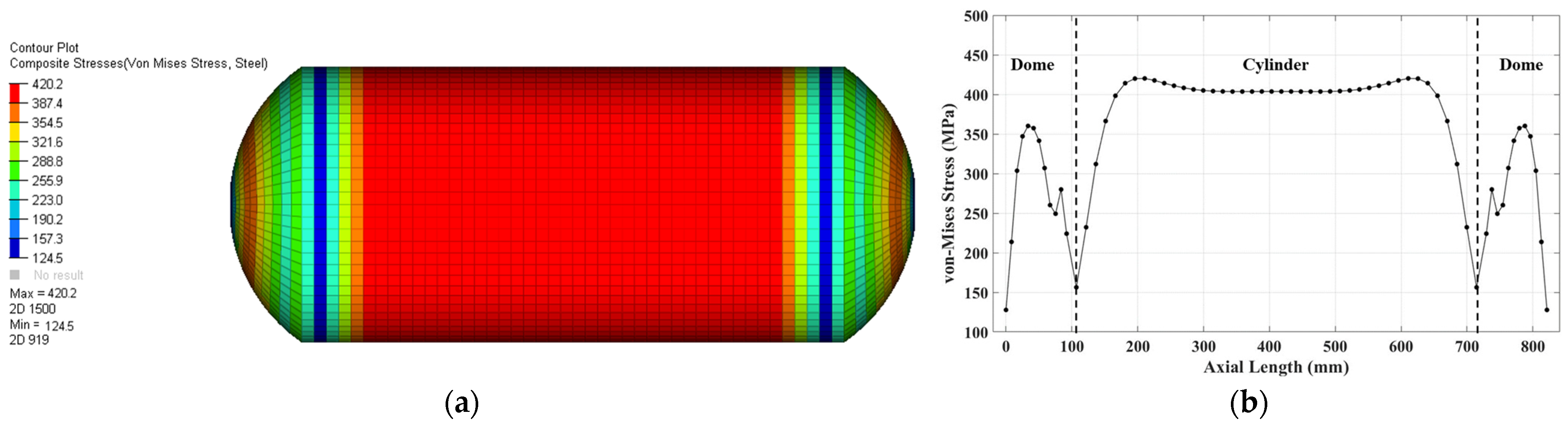
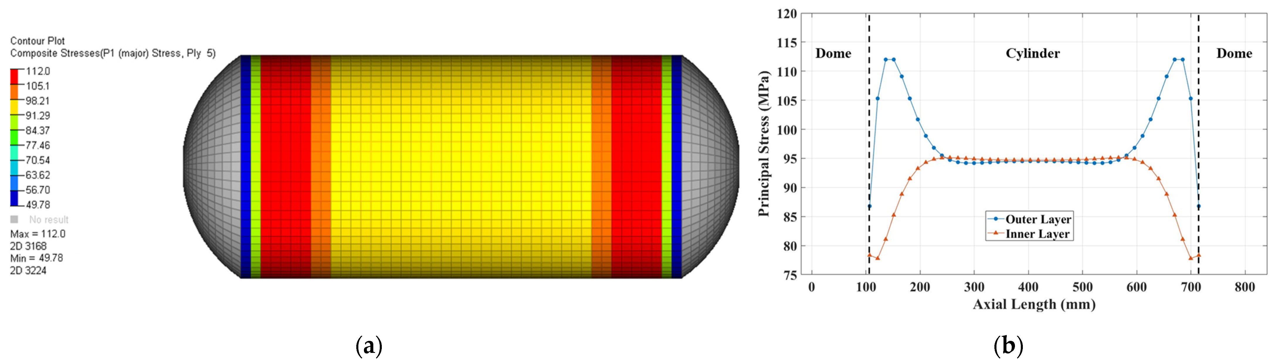
2.4. Finite Element Analysis

A static structural analysis was performed on the Type 2 COPV to calculate the maximum von Mises stresses developed in the steel liner, the maximum principal stresses imposed on each layer of the composite and the Tai-Wu failure index. At first, the least deformation occurred near the cylinder wrapped by the composite layer in the steel liner, resulting in a maximum von Mises stress of 420.2 MPa. This is shown in Figure 4.
The maximum principal stress occurred in the 10th ply of the composite layer. The most deformation occurred at the ends of the cylinder adjacent to the dome, resulting in a lower principal stress. However, the maximum principal stress was calculated to be 112.0 MPa at a point 40 mm from both ends of the composite layer. A comparison of the principal stress distribution in the outer layer and the inner layer is shown in Figure 5b. From the inside out, principal stress was calculated to be higher near the edges of the cylinder, and there was little difference in the principal stress in the center of the cylinder. The results of the maximum principal stress calculation according to the stacking order are shown in Figure 6.
The Tsai–Wu failure index determines whether the composite structure is a failure. The maximum Tsai–Wu failure index is calculated to be highest at the 10th ply, which is the outer composite layer. The maximum Tsai–Wu failure index is 0.808, and both ends of the 10th ply are most susceptible to fracture. Since the Tsai–Wu Failure Index is less than 1, it is confirmed that the initial design model will not fail. This is shown in Figure 7.

3. Weight Minimization of Type 2 COPV

Figure 8 is a flowchart showing the research procedure of weight minimization in this study. First, the initial Type 2 COPV model was subjected to internal pressure, and the finite element analysis was performed to calculate the von Mises stresses in the steel liner and the principal stresses in the composite layer. A full factorial design (FFD) was performed to generate sampling data. A sensitivity analysis using FFD data was then performed to analyze the effect of the design variables on the responses. Then, significant design variables were used to generate the kriging metamodel. Next, we created an optimal design problem formulation to minimize the weight while satisfying the safety constraints of the composite layer and steel liner. The optimization was performed using the genetic algorithm (GA) that guarantees a global optimal solution.

3.1. Optimal Design Problem Formulation

The optimal design problem formulation for minimizing the weight of a Type 2 COPV is shown in Equation (12).
Find x _ i   ( i = 1 , , 4 ) Minimize W ( k g ) Subject   to T s a i W u   f a i l u r e   i n d e x <   1   M a x i m u m   v o n M i s e s   s t r e s s   i n   s t e e l   l i n e r < 650   ( M P a )
The design parameters were set to minimize the weight of the Type 2 COPV considering the manufacturing process. Four design variables were selected: steel liner thickness ( x 1 ) and ply thickness ( x 2 ), which affect the weight, and ply orientation ( x 3 ) and number of plies ( x 4 ), which affect the failure of the composite structure. This is shown in Figure 9. The steel liner thickness was set as a design variable to consider the failure of the dome part, and the ply thickness, ply orientation, and number of plies were set as design variables considering the characteristics of the COPV manufactured through the filament winding method.
The range of each design variables is shown in Table 2. The objective function was to minimize the weight (W). As a constraint, the Tsai–Wu Failure Index was defined not to exceed 1 to prevent failure of the composite layer due to burst pressure, and the maximum von Mises stress in the steel liner was defined not to exceed 650 MPa, the tensile strength of steel 201, to prevent failure of the metal liner.

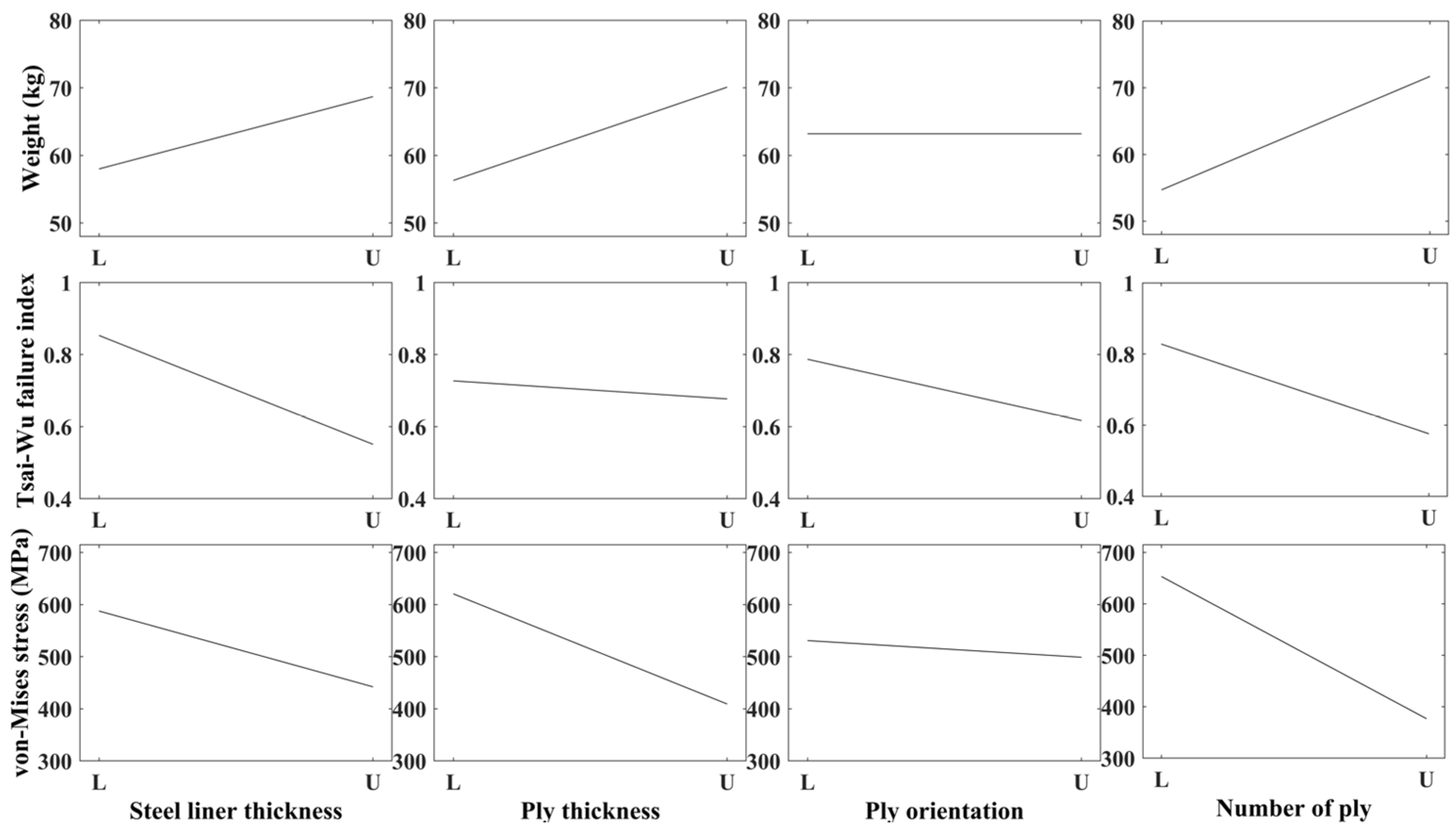
3.2. Design Sensitivity Analysis and Kriging Metamodel Using Design of Experiments

The design of experiments (DoE) method to extract sampling points from a given range of design variables was performed to perform a sensitivity analysis and generate the metamodel. We used the full factorial design (FFD), a method that samples all experimental points for a user-defined number of levels for each design variable. For the four design variables, a total of 625 sampling points were generated by performing the DoE at five levels. We used the sensitivity analysis and the analysis of means (ANOM) extracted from the DoE, and the results are shown in Figure 10 and Figure 11, which present an analysis of the effect of each design variable on the objective function and constraints.
Figure 10 shows the effect of design variables on the responses using ANOM, where L represents the lower bound of each design variable and U represents the upper bound of each design variable. As shown in Figure 10, the design variable that has the greatest effect on weight is the number of plies, with ply orientation having no effect. For the Tsai–Wu failure index of the composite layer, steel liner thickness, ply orientation, and the number of plies have influence, in that order. The design variables that affect the von Mises stress of the steel liner are the number of plies, ply thickness, and steel liner thickness. Given the sensitivity of the design variables to the responses, all the initially set design variables are considered to be significant.
Figure 11 shows the significance of the design variables on the responses using the sensitivity analysis. While changing the ply orientation does not affect the weight, it does affect the Tsai–Wu failure index and von Mises stress. In addition, the other design variables, such as steel liner thickness, ply thickness, and the number of plies, were identified as influencing all three responses.
Composite structures are mostly brittle and exhibit strong nonlinearity compared to typical metal structures. In addition, COPVs can exhibit nonlinearity at any region of each design parameter depending on the ply orientation and number of plies. Therefore, the kriging metamodel was generated to reduce the computational cost. It is suitable for design problems with strong nonlinearity. The kriging metamodel is a method of interpolating sampling points using a regression model and residual terms and is shown in Equation (13) [31].
y ( x ) = f ( x ) + Z ( x )
where y x is the response approximation function, f ( x ) is the regression model expressed as the nth-degree polynomial, and Z ( x ) is the residual term. The regression model f(x) approximates the response over the entire design range, and Z ( x ) represents the error between the regression model and the results calculated at each sampling points. Of the 625 sampling data, 500 were used to generate the kriging metamodel and the remaining 125 were used to calculate the accuracy of the metamodel. The root mean square error (RMSE) was used to calculate the accuracy of the kriging metamodel. For the calculation of RMSE, the calculated value using the metamodel and finite element analysis was compared. The results of the RMSE calculation are shown in Table 3.
According to the RMSE results, the relative errors between the actual and predicted values for the weight, Tsai–Wu failure index, and von Mises stress were calculated to be small, confirming the high prediction accuracy of the metamodel.

3.3. Optimization Using Genetic Algorithms

Due to the strong nonlinearity of composite structures, it is necessary to use a global optimization algorithm to determine the optimal solution. In this study, the optimal design was performed using a genetic algorithm that guarantees a global optimal solution. It was developed based on Darwin’s concept of natural selection as one of the optimization methods to obtain a global optimal solution [32].
This is an overview of the genetic algorithm’s operation. First, a new population is formed based on randomly generated initial sampling points. The generated population is then evaluated to determine if it is optimal. If the terminating condition is not satisfied, it prepares to create a new population through crossover, mutation and elitist policy. This process is continued until the fitness value is satisfied.
We defined the parameters required to use the genetic algorithm to perform weight minimization. Furthermore, 20 populations were produced per generation, and the iterations were limited to a minimum of 20 and a maximum of 50 and to stop terminating the search if the weight did not improve after 15 generations.

3.4. Optimization Results

The weight decreased with iterations and finally converged after 25 iterations. This is shown in Figure 12. As a result of the optimization, the steel liner thickness was 2.94 mm, the ply thickness was 0.5 mm, the ply orientation was 32.22°, and the number of plies was 15. The weight of the COPV was mainly due to the steel liner thickness, which was reduced by 15.64% while satisfying the constraints. The total laminate thickness was initially 10 mm, but it was reduced to 7.5 mm by decreasing the ply thickness to 0.5 mm and increasing the number of plies to 15. The weight decreased by 26.57%, from 81.62 kg to 59.93 kg. Both the Tsai–Wu failure index and the maximum von Mises stress in the liner were calculated to be 0.802 and 647.3 MPa, so the constraints were satisfied. The optimization results are shown in Table 4.
The finite element analysis was performed using the optimal solution of the calculated design parameters and compared with the initial analysis values. The von Mises stress distribution in the optimization model is shown in Figure 13 and Figure 14. As the steel thickness decreased in comparison to the initial model, the von Mises stress distribution in the cylinder was the same, but a significant difference occurred in the dome section, where the maximum von Mises stress occurred.
Next, the principal stress distribution of the composite layer in the optimization model is shown in Figure 15 and Figure 16. As with the initial model, the principal stress distribution near the center of the cylinder was calculated similarly, but the values were increased by an overall factor of about 1.36. The maximum principal stress occurred at the same point.

4. Conclusions

In this study, the weight minimization for the Type 2 COPV was conducted considering the kriging metamodel for mechanical safety. First, the von Mises stress on the steel liner and the Tsai–Wu failure index of the composite layer were calculated using finite element analysis. The finite element analysis result showed that von Mises stress in the steel liner was calculated to be 420.2 MPa lower than the ultimate tensile stress, and the Tsai–Wu failure index in the composite layer was calculated to be 0.808, confirming the mechanical safety.
The optimization set the weight minimization of the Type 2 COPV as the objective function and the failure index of the steel liner and composite layer as the constraint to achieve the optimal design to reduce the weight while ensuring mechanical safety. The design variables selected were steel liner thickness, ply thickness, ply orientation, and number of plies. A five-level full factorial design was conducted on the four design variables to generate 625 data points. The data were used to generate the kriging metamodel and perform the sensitivity analysis.
The weight minimization was conducted on the generated kriging metamodel using the genetic algorithm. The optimization resulted in a weight reduction of 26.57% compared to the initial model while satisfying the constraints. The weight of the COPV was most affected by the 15.64% reduction in steel liner thickness. And, the total laminate thickness was initially 10 mm, but it was reduced to 7.5 mm by decreasing the ply thickness to 0.5 mm and increasing the number of plies to 15. We compared the results of the finite element analysis between the initial and optimal models using optimal design variables. The point where the maximum von Mises stress occurred changed from the cylinder part to the dome part, and the value increased by about 1.5 times. The distribution of the maximum principal stress of the composite layer was the same. Only the value increased.
The optimization process used in this study can be applied not only to COPVs used in FCEVs but also to composite structures. It has the advantage of an accurate optimal solution with a low computational cost in optimal design problems for composite structures with strong nonlinearity. In this study, we only considered the design under static pressure, but in future research, it is necessary to consider dynamic loads such as impact.

Author Contributions

Conceptualization, J.A., H.L. and C.-W.K.; methodology, J.A., H.L. and C.-W.K.; software, J.A. and H.L.; validation, J.A. and H.L.; formal analysis, J.A.; investigation, J.A.; resources, J.A.; data curation, J.A. and H.L.; writing—original draft preparation, J.A.; writing—review and editing, J.A., H.L. and C.-W.K.; visualization, J.A. and H.L.; supervision, C.-W.K.; project administration, C.-W.K.; funding acquisition, C.-W.K. All authors have read and agreed to the published version of the manuscript.

Funding

This paper was supported by the Konkuk University Researcher Fund in 2022 and the Technology Innovation Program (20012518) funded by the Ministry of Trade, Industry and Energy (MOTIE, Korea) and the National Research Foundation of Korea (NRF) grant funded by the Korean Government’s Ministry of Science, ICT and Future Planning (No. 2019R1A2C1090228).

Data Availability Statement

Data are contained within the article.

Conflicts of Interest

The authors declare no conflicts of interest.

References

  1. Almeida, D.; Silvio, C.A.; Kruczan, R. Effects of drivetrain hybridization on fuel economy, performance and costs of a fuel cell hybrid electric vehicle. Int. J. Hydrogen Energy 2021, 46, 39404–39414. [Google Scholar] [CrossRef]
  2. Andrzej, S.; Pielecha, I.; Cieslik, W. Fuel cell electric vehicle (FCEV) energy flow analysis in real driving conditions (RDC). Energies 2021, 14, 5018. [Google Scholar]
  3. Cano, Z.P.; Banham, D.; Ye, S.; Hintennach, A.; Lu, J.; Fowler, M.; Chen, Z. Batteries and fuel cells for emerging electric vehicle markets. Nat. Energy 2018, 3, 279–289. [Google Scholar] [CrossRef]
  4. Toktaş-Palut, P. The fuel cell electric vehicle market growth: Analyses of contracts and government incentives. Comput. Ind. Eng. 2023, 176, 108988. [Google Scholar] [CrossRef]
  5. Hwang, H.J.; Lee, Y.H.; Seo, I.; Chung, Y. Successful pathway for locally driven fuel cell electric vehicle adoption: Early evidence from South Korea. Int. J. Hydrogen Energy 2021, 46, 21764–21776. [Google Scholar] [CrossRef]
  6. Joshi, A.; Sharma, R.; Baral, B. Comparative life cycle assessment of conventional combustion engine vehicle, battery electric vehicle and fuel cell electric vehicle in Nepal. J. Clean. Prod. 2022, 379, 134407. [Google Scholar] [CrossRef]
  7. Bødal, E.F.; Mallapragada, D.; Botterud, A.; Korpås, M. Decarbonization synergies from joint planning of electricity and hydrogen production: A Texas case study. Int. J. Hydrogen Energy 2020, 45, 32899–32915. [Google Scholar] [CrossRef]
  8. Samsatli, S.; Staffell, I.; Samsatli, N.J. Optimal design and operation of integrated wind-hydrogen-electricity networks for decarbonizing the domestic transport sector in Great Britain. Int. J. Hydrogen Energy 2016, 41, 447–475. [Google Scholar] [CrossRef]
  9. Dumbrava, I.D.; Cormos, C.C. Techno-economical evaluations of decarbonized hydrogen production based on direct biogas conversion thermos-chemical looping cycles. Int. J. Hydrogen Energy 2021, 46, 23149–23163. [Google Scholar] [CrossRef]
  10. Lee, J.J.; Kim, D.H.; Choi, Y.J.; Kim, C.W.; Lee, S.S. Design Optimization of Type 2 Composite Overwrapped Pressure Vessel for Fuel Cell Vehicle using Finite Element Method. Trans. Korean Soc. Mech. Eng. 2020, 44, 241–246. [Google Scholar] [CrossRef]
  11. Alcantar, V.; Ledesma, S.; Aceves, S.M.; Ledesma, M.; Saldana, A. Optimization of type III pressure vessels using genetic algorithm and simulated annealing. Int. J. Hydrogen Energy 2017, 42, 20125–20132. [Google Scholar] [CrossRef]
  12. Jeong, S.M.; Hwang, T.K. Research on Laminate Design Parameters to Maximize Performance Index of Composite Pressure Vessel. J. Korean Soc. Propuls. Eng. 2018, 22, 21–27. [Google Scholar] [CrossRef]
  13. Barthélémy, H.; Weber, M.; Barbier, F. Hydrogen storage: Recent improvements and industrial perspectives. Int. J. Hydrogen Energy 2017, 42, 7254–7262. [Google Scholar] [CrossRef]
  14. Kang, H.; He, P.; Zhang, C.; Dai, Y.; Lv, H.; Zhang, M.; Yang, D. Stress–strain and burst failure analysis of fiber wound composite material high-pressure vessel. Polym. Polym. Compos. 2021, 29, 1291–1303. [Google Scholar] [CrossRef]
  15. Annaratone, D. Pressure Vessel Design; Springer: Berlin, Germany, 2007; pp. 12–49. [Google Scholar]
  16. Son, D.S.; Hong, J.H.; Chang, S.H. Determination of the autofrettage pressure and estimation of material failures of a Type III hydrogen pressure vessel by using finite element analysis. Int. J. Hydrogen Energy 2012, 37, 12771–12781. [Google Scholar] [CrossRef]
  17. Raponi, E.; Fiumarella, D. Experimental analysis and numerical optimization of a thermoplastic composite in crashworthiness. IOP Conf. Ser. Mater. Sci. Eng. 2021, 1038, 012030. [Google Scholar] [CrossRef]
  18. Mian, H.H.; Wang, G.; Dar, U.A.; Zhang, W. Optimization of composite material system and lay-up to achieve minimum weight pressure vessel. Appl. Compos. Mater. 2013, 20, 873–889. [Google Scholar] [CrossRef]
  19. Sulaiman, S.; Borazjani, S.; Tang, S.H. Finite element analysis of filament-wound composite pressure vessel under internal pressure. IOP Conf. Ser. Mater. Sci. Eng. 2013, 50, 012061. [Google Scholar] [CrossRef]
  20. Lin, D.T.W.; Hsieh, J.C.; Chindakham, N. Optimal design of a composite laminate hydrogen storage vessel. Int. J. Energy Res. 2013, 37, 761–768. [Google Scholar] [CrossRef]
  21. Alemida, J.H.S., Jr.; Faria, H.; Marques, A.T.; Amico, S.C. Load sharing ability of the liner in type III composite pressure vessels under internal pressure. J. Reinf. Plast. Compos. 2014, 33, 2274–2286. [Google Scholar] [CrossRef]
  22. Leh, D.; Magneville, B.; Saffré, P.; Francescato, P.; Arrieux, R.; Villalonga, S. Optimisation of 700 bar type IV hydrogen pressure vessel considering composite damage and dome multi-sequencing. Int. J. Hydrogen Energy 2015, 40, 13215–13230. [Google Scholar] [CrossRef]
  23. Alcántar, V.; Aceves, S.M.; Ledesma, E.; Ledesma, S.; Aguilera, E. Optimization of Type 4 composite pressure vessels using genetic algorithms and simulated annealing. Int. J. Hydrogen Energy 2017, 42, 15770–15781. [Google Scholar] [CrossRef]
  24. Kim, C.U.; Hong, C.S.; Kim, C.G.; Kim, J.Y. Optimal design of filament wound type 3 tanks under internal pressure using a modified genetic algorithm. Compos. Struct. 2005, 71, 16–25. [Google Scholar] [CrossRef]
  25. Paknahad, A.; Fathi, A.; Goudarzi, A.M.; Nourani, R. Optimum head design of filament wound composite pressure vessels using a hybrid model of FE analysis and inertia weight PSO algorithm. Int. J. Mater. Form. 2014, 9, 49–57. [Google Scholar] [CrossRef]
  26. Ban, B.; Sripetic, S. Systematic metamodel-based optimization study of synchronous reluctance machine rotor barrier topologies. Machines 2022, 10, 712. [Google Scholar] [CrossRef]
  27. Vafaeesefat, A. Optimization of composite pressure vessels with metal liner by adaptive response surface method. J. Mech. Sci. Technol. 2011, 25, 2811–2816. [Google Scholar] [CrossRef]
  28. The International BMW Website. Available online: https://www.bmw.com/en/innovation/how-hydrogen-fuel-cell-cars-work.html (accessed on 28 November 2023).
  29. Kim, C.W.; Hwang, W.B.; Park, H.C.; Han, K.S. Stacking sequence optimization of laminated plates. Compos. Struct. 1997, 39, 283–288. [Google Scholar] [CrossRef]
  30. Kim, C.W.; Song, S.R.; Hwang, W.B.; Park, H.C.; Han, K.S. On the failure indices of quadratic failure criteria for optimal stacking sequence design of laminated plate. Appl. Compos. Mater. 1994, 1, 81–85. [Google Scholar] [CrossRef]
  31. Zhu, W.G.; Meng, Z.J.; Huang, J.; He, W. Optimization design for laminated composite structure based on kriging model. Appl. Mech. Mater. 2012, 217, 179–183. [Google Scholar] [CrossRef]
  32. Adeli, H.; Cheng, N.T. Integrated genetic algorithm for optimization of space structures. J. Aerosp. Eng. 1993, 6, 315–328. [Google Scholar] [CrossRef]
Figure 2. Type 2 composite overwrapped pressure vessel model: (a) geometry; (b) stacking sequence.
Machines 12 00132 g002
Figure 3. (a) Cylindrical section of Type 2 COPV; (b) stress resultant of laminated plate.
Machines 12 00132 g003
Figure 4. (a) Von Mises stress distribution in steel liner; (b) von Mises stress in longitudinal direction for steel liner.
Machines 12 00132 g004
Figure 5. Principal stress distribution in composite layer: (a) principal stress for 10th ply; (b) principal stress in the longitudinal direction for the outer layer and inner layer.
Machines 12 00132 g005
Figure 6. Maximum principal stress profile with ply number.
Machines 12 00132 g006
Figure 7. Tsai–Wu failure index distribution in 10th ply.
Machines 12 00132 g007
Figure 8. Flowchart of the optimization process.
Machines 12 00132 g008
Figure 9. Design variables of Type 2 COPV.
Machines 12 00132 g009
Figure 10. ANOM of design variables for responses.
Machines 12 00132 g010
Figure 11. Design sensitivity with respect to design variables.
Machines 12 00132 g011
Figure 12. Optimization iteration history of objective function for weight.
Machines 12 00132 g012
Figure 13. Comparison of von Mises stress in steel liner: (a) initial model; (b) optimized model.
Machines 12 00132 g013
Figure 14. Comparison von Mises stress distribution in steel liner of initial and optimal model.
Machines 12 00132 g014
Figure 15. Comparison of principal stress in composite layer: (a) initial model; (b) optimized model.
Machines 12 00132 g015
Figure 16. Comparison principal stress distribution in composite layer of initial and optimal model.
Machines 12 00132 g016
Table 1. Material properties of steel 201 and CFRP.
Steel 201CFRP
Longitudinal young’s modulus (E1)210 GPa142 GPa
Transverse young’s modulus (E2)-10.8 GPa
Poisson’s ratio (ν12)0.30.27
Shear modulus XY (G12), XZ (G2Z)76.9 GPa5.5 GPa
Shear modulus YZ (G1Z)-3.9 GPa
Longitudinal tensile strength (Xt)0.311 GPa1.568 GPa
Transverse tensile strength (Yt)-1.341 GPa
Table 2. Design variables and their bounds.
Design VariablesBoundary
Steel liner thickness (mm) 1     x 1   6
Ply thickness (mm) 0.5     x 2   1.2
Ply orientation (degree) 10     x 3   60
Number of plies (ea) 5     x 4   15
Table 3. Accuracy of the kriging metamodel.
ResponseRMSE (Training)RMSE (Test)
Weight 1 × 10 12 0.00023
Tsai–Wu failure index 3 × 10 12 0.00197
Von Mises stress 1 × 10 12 0.00071
Table 4. Comparison of objective function, constraints, and design variables of Type 2 COPV.
Initial ValueOptimal ValueRate of Change
Design variablesSteel liner thickness (mm)3.42.94−15.64%
Ply thickness (mm)10.5−100%
Ply orientation (degree)3032.227.4%
Number of plies (ea)101550 %
Objective functionWeight (kg)81.6259.93−26.57%
ConstraintsTsai–Wu failure index in composite layer0.8080.93215.35%
Max. von Mises stress in steel liner (MPa)420.2647.354.05%
Disclaimer/Publisher’s Note: The statements, opinions and data contained in all publications are solely those of the individual author(s) and contributor(s) and not of MDPI and/or the editor(s). MDPI and/or the editor(s) disclaim responsibility for any injury to people or property resulting from any ideas, methods, instructions or products referred to in the content.

