Article

Research on the Influence of Disc–Drum Connection Bolt Preloading Rotor Assembly Modal Characteristics and Diagnosis Technology

1
School of Aeronautics, Northwestern Polytechnical University, 127 Friendship West Road, Xi’an 710072, China
2
College of Automation, Wuxi University, 333, Xishan Road, Wuxi 214105, China
*
Author to whom correspondence should be addressed.
Machines 2024, 12(1), 83; https://doi.org/10.3390/machines12010083
Submission received: 21 December 2023 / Revised: 13 January 2024 / Accepted: 16 January 2024 / Published: 22 January 2024
(This article belongs to the Special Issue Aerodynamic Design and Optimization for Turbomachinery)

Abstract

:
The drum rotor of an aero-engine is connected by one or multiple mounting edges through bolts, and their dynamics are significantly influenced by the preload state of the bolts. Long working hours in challenging environments can result in the deterioration of bolt pre-tightening during assembly or service, which impacts the rotor’s dynamic stability and overall performance. Currently, there are no available methods for detecting the dynamic characteristics of the drum connection components. This paper analyzes the impact of the natural characteristics of the drum composite structure of a high-pressure aero-engine turbine based on the refined finite element method when the preloading state changes. Two conditions of deviation and uneven stiffness distribution were applied to the connected components of the drum. The analysis focused on the impact of the pre-tightening state on its natural frequency. After analyzing the feasibility of identifying the pre-tightening state, two methods are proposed. These methods focus on changes in natural frequency and mode shape, specifically the sensitive natural frequency change method and the mode step change method. The methods proposed in this paper can serve as a reference for evaluating the quality of assembling complex disc–drum structures with multiple bolt connections.

1. Introduction

During the assembly of an aero-engine, even when the same engine parts are assembled using the same assembly process methods and parameters, different assembly batches will result in varying vibration levels or response characteristics of the entire machine. Small deviations in individual assembly process parameters can lead to significant changes in the vibration response of the entire machine [1,2]. The reason for this phenomenon is the complexity of the rotor’s structure. Manufacturing and assembly errors in the components can lead to changes in the connection stiffness of the mating surfaces, which can significantly impact the rotor’s dynamic performance and further affect the vibration characteristics of the entire machine [3]. Each shaft disc on the rotor is connected by bolts and assembled via manual tightening. Due to the influence of tightened process limitations, there is a significant pre-tightening deviation (reaching up to 40–60% with a high degree of dispersion) after assembly or service for a certain period, which directly affects the dynamic performance of the rotor and even the entire aero-engine. While the geometric machining accuracy of each rotor part is high and the rotor assembly is strictly controlled, ensuring that the static characteristics of the rotor detection index are within the allowable range, there is a lack of detection technology for the dynamic characteristics of the rotor after assembly. This results in the rotor system exhibiting vibration out-of-tolerance phenomenon on the test bench despite having qualified static indicators after assembly. Therefore, it is of great significance to study the dynamic characteristics detection technology of aero-engine rotor components after assembly or service and to improve the overall engine’s dynamic stability.
Researchers typically assess the dynamic characteristics of a structure using indicators such as damping ratio, natural frequency, mode shape, and vibration phase difference. The transfer function of a structure is significantly influenced by the pre-tightening state, which is mainly manifested as follows: When the bolt pre-tightening state is optimal, it maintains stable characteristics in a linear state. However, when the pre-tightening state of the bolt deteriorates, it results in a decrease in connection stiffness, leading to a significant alteration in the transfer function of the bolt flange surface and subsequently impacting the modal and vibration characteristics of the structure [4]. In recent years, researchers have conducted extensive research on the impact of changes in bolt pre-tightening on the dynamic characteristics of structures [5].
He X L et al. [6] used the experimental analysis method to study the influence of bolt loosening on the vibration characteristics of the tower. The results show that the first-order natural frequency, vibration mode, and damping ratio are not sensitive to the change in preload state, while the first-order phase difference characteristics of the wind turbine tower are obviously affected by the loosening of flange bolts. Qin [7] took the typical disk-drum connection structure on the aero-engine rotor as the object and used the finite element method to study the influence of bolt loosening on the time-varying stiffness of the connection interface. Based on the vibration method, K He [8] analyzed the influence of bolt loosening on the natural frequency and vibration response of the structure by taking the bolted pipe structure as the object. The results show that when the bolt preloading state changes, the first few natural frequencies of the structure change significantly, which can be used as an index to detect whether the bolt of the pipeline structure is loose. Shuguo L [9] studied the time-varying stiffness and dynamic response of the bolted drum rotor to the number of bolts, bolt looseness, and system speed.
Yu Liu [10] obtained the stiffness characteristics and shaft bending characteristics of flange connection after bolt failure via numerical simulation and experimental tests. The rotor motion equation with local stiffness asymmetry and initial bending characteristics caused by flange connection bolt failure was established. The dynamic characteristics of the rotor system were further studied. Finally, the frequency spectrum and orbit of the shaft center of the rotor were obtained via experimental analysis, which verified the accuracy of the numerical analysis. Li [11] established a rotor model of the rod-fastened rotor using the lumped mass method, considering the contact effect, and solved the model using the Runge–Kutta method. The influence of contact stiffness on the dynamic characteristics of the rotor was studied. According to the research, the uniform relaxation of the interface will affect the motion state of the system, resulting in different changes in the response state and the frequency increasing the amplitude by approx. a factor of two at different speeds. When the non-uniform relaxation occurs at the interface, it will only change the amplitude of the vibration and will not affect the motion state of the system. Beaudoin [12] used a small number of one-dimensional spring elements and contact elements to simulate the nonlinear contact behavior of the rabbet bolt, and the influence of the rabbet bolt connection on the vibration characteristics of the rotor structure was analyzed.
In addition, scholars have conducted numerous studies on the dynamic characteristics of simple structures with a small number of bolts. These studies consider the effects of pre-tightening state changes through a combination of theory, simulation, and experiments. This provided a wealth of results [13,14]. Many researchers use changes in vibration signals as an indicator to identify the pre-tightening state of structures [15,16,17]. Nguyen [18] has fully integrated the advantages of impedance technology and deep learning algorithms to propose a new method for identifying bolt loosening with automatic impedance feature extraction. Tang Tao [19] took the real flange structure as the object and obtained the law between different damage statistical indexes and bolt loosening of flange structure via experimental method. They pointed out that the improved damage index root mean square change rate (RMSCR) was related to the position and degree of bolt loosening of the flange structure and was less affected by structural differences. Therefore, it can be used to identify the bolt preload state of the flange structure.
Yue [20] analyzed the influence of missing bolts on the dynamic characteristics of high-pressure rotors using numerical simulation, and a rotor test bench was built that can carry out impact and frequency scanning experiments under axial tensile force. Based on the obtained vibration response characteristics, the loss function of the average absolute error and the extreme gradient boosting decision method are used to predict the missing position of the bolt. The results show that the prediction accuracy of the model can reach more than 90%. In addition, the evaluation index of the determination coefficient of the prediction effect reaches 0.9, which is significantly higher than other conventional models, such as multiple linear regression and multiple adaptive regression splines. Gong [21] proposed a method based on subharmonic resonance and adaptive stochastic resonance (ASR) to identify whether the bolt is loose. Through numerical simulation and experimental verification of a typical single bolt connection model, it is proved that this method can effectively identify bolt loosening under a strong noise background. Zhang [22] proposed an assembly tightness identification method for bolted joints based on modified ensemble empirical mode decomposition (MEEMD) and genetic algorithm least squares support vector machine (GALSSVM), and the accuracy of the proposed algorithm was verified by designing multiple sets of case experiments with different preloads. Huda [23] systematically positioned vibration sensors during the vibration test and assessed the extent of bolt loosening by analyzing the high-frequency fluctuations in the obtained vibration signal.
In summary, the majority of the existing literature focuses on researching the influence of the preload state on the dynamic characteristics of structures and identifying the preload state of structures through vibration characteristic parameters. However, there is limited research on the method for identifying the preload state using the disc drum assembly of aircraft development as the subject. Compared to other connecting structures, the disc drum assembly has distinctive structural characteristics. It is assembled by a large number of bolts from multiple connected parts, and there are limitations in the established preload identification methods for simple and less-bolted structures. Therefore, it is necessary to explore a new method for identifying the preload in the disc–drum assembly. This paper first explains the principle of structural preload identification, then introduces the characteristics of the turbine disc–drum combination structure and force analysis and establishes its three-dimensional refined finite element model to study the influence of the preload state of the bolts on the modal characteristics of the disc–drum combination structure. Finally, according to the theoretical and modal calculation results, this study proposes the sensitive intrinsic frequency change method and modal mode step method. These methods can be used to identify the preloaded state of the multi-bolt disc–drum assembly, and they have practical engineering significance.

2. Structural Preload State Diagnosis Theory

When a structure responds to an external transient excitation, it naturally vibrates at a specific frequency, which is the natural frequency of the structure. Typically, a structure has multiple natural frequencies that can be readily determined through modal tests. The natural frequency is not affected by external excitation and is an inherent property of the structure. When its mass and stiffness are determined, its value will no longer change. When the damping effect is neglected, the eigenvalue equation for structural vibration is:
( K ω i 2 M ) ϕ i = 0
where K is the overall stiffness matrix of the structure, M is the overall mass matrix of the structure, ωi is the i-th order natural frequency of the structure, and ϕi is expressed as the modal eigenvector. In bolted structures, when the preload state is altered, it causes a certain amount of change in the stiffness, frequency, and mode vector of the structure. ΔK, Δωi, and Δϕi can be indicated in Equation (2).
( K + Δ K ) ( ω i 2 + Δ ω i 2 ) M ( ϕ i + Δ ϕ i ) = 0
By performing a left-multiplication of the above equation with ϕ i T , followed by expansion and disregarding terms of the second order, further simplification of the above equation can be obtained:
Δ ω i 2 = ϕ i T Δ K ϕ i
Typically, the stiffness of a bolted structure will change to some extent with the change in preload state, which, in turn, leads to a change in the natural frequency of the structure in a certain interval range. However, in practice, the rotor structure is complex, the number of connecting bolts is large, and the bolt preloading force is strictly controlled in the assembly process, so it is difficult to directly reflect the bolt preloading force deviation and local loosening problems existing in engineering on the natural frequency. Therefore, we can decrease the K value of the mating surfaces by applying a tensile force on the structure. When the K value is maintained within a relatively low range, a slight alteration in the preload state can lead to a significant shift in the natural frequency of specific sensitive orders. This, in turn, can be utilized to investigate and identify the preload state of the mating surfaces of the structure.
In addition, based on perturbed theory, the feasibility of diagnosis of structural preload state can be analyzed from the change in structural mode shape. Perturbed theory shows that after small changes in structural parameters, the natural frequency and mode shape of the structure will also change accordingly, and the modal step phenomenon may occur [24]. The modal mode step refers to the sequence exchange or dislocation between the modal modes of the structural system, which is manifested as the conversion of the low-order modal mode vector before perturbation into the higher-order modal mode vector after perturbation.
The general equation of structural dynamics is as follows:
M x ¨ + C x ˙ + K x = F t
where M is the global mass matrix of the structure, C is the global damping matrix of the structure, K is the global stiffness matrix of the structure, x ¨ is the acceleration vector of the structural node, x ˙ is the velocity vector of the structural node, x is the displacement vector of structural node, and F(t) is the external load vector of the structure.
By solving the natural frequency and mode vector, the result can be obtained in Formula (5):
K ω i 2 M u = 0
where ωi and u are the natural frequency and mode shape vectors corresponding to the i-th order mode.
According to Formula (5), the eigenvalue problem of the structure is
K u = λ M u
where λ is the character value, λ = ω 2 , and ω is the angular frequency.
When the bolt preload deviates, it may cause a small detuning, so the mass matrix and stiffness matrix become:
K = K 0 + ξ K 1
According to the canonical perturbation theory [24], the eigenvalues and eigenvectors can be expanded into power series based on ξ .
λ i = λ 0 i + ξ λ 1 i + ξ 2 λ 2 i +
u i = u 0 i + ξ u 1 i + ξ 2 u 2 i +
where the subscript ‘0’ represents the ideal preload state of the structure, and the subscripts ‘1’ and ‘2’ represent the first-order and second-order perturbation states, respectively. Additionally, ξ is a small parameter.
The pre-perturbation eigenvalue ordering has λ 0 i < λ 0 i + 1 . For a modally dense structure, the eigenvalue first-order perturbation may satisfy
λ 1 i λ 1 i + 1 > λ 0 i + 1 λ 0 i ξ
According to Formula (11), it can be obtained that
λ i = λ 0 i + ξ λ 1 i > λ 0 i + 1 + ξ λ 1 i + 1 = λ i + 1
As can be seen from Formula (11), the order of adjacent eigenvalues changes after perturbation, and the corresponding modal modes and eigenvalues also change; that is, the low-order frequency after detuning corresponds to the high-order modes before detuning, and the high-order frequency after detuning corresponds to the low-order mode modes before detuning, and the structure has a modal mode step. According to the above theoretical analysis, the preload state of the structure can be diagnosed by judging whether the jump phenomenon occurs in the structural modal mode.

3. Structural Characteristics and Force Analysis of Turbine Disc–Drum Combination Structure

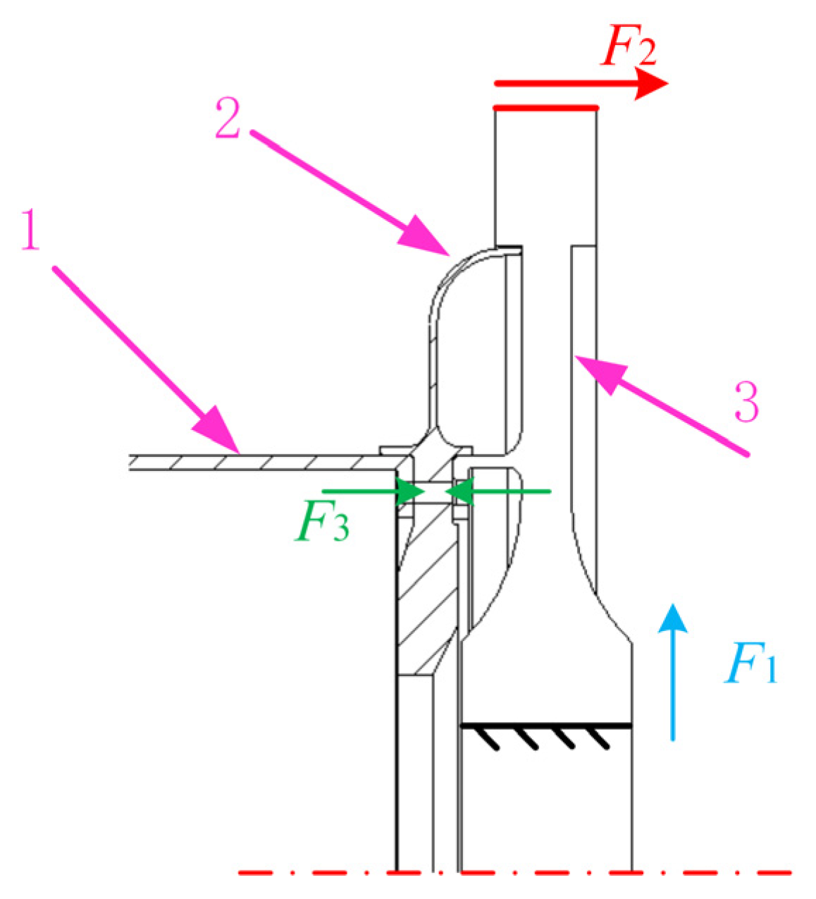
The high-pressure turbine disc–drum assembly is mainly composed of drum shaft 1, labyrinth teeth plate 2, and high-pressure turbine disc 3, as shown in Figure 1. The drum shaft, labyrinth teeth plate, and high-pressure turbine plate are tightly connected by 48 uniformly circumferential distributed bolts (M8) in series at the rabbet. The high-pressure turbine disc is a disk-like structure with a large diameter and a large mass in the outer ring of the disk-like structure, which requires a large centrifugal force. Compared with high-pressure turbines, the drum shaft is mainly a thin-walled cylindrical structure with a smaller rotation radius, which is less centrifugal force than the high-pressure turbine disc. In summary, it is evident that high-speed rotation of the disc–drum assembly can cause inconsistent deformation of the drum shaft and the turbine disc in the radial direction. This inconsistency may directly lead to deformation inconsistencies in the bonding surface between the high-pressure turbine disc, the drum shaft, and the labyrinth teeth plate.
In practice, the maximum speed can reach 18,800 revolutions per minute (r/min) based on the output power of the aircraft engine. The high-pressure turbine disc drives the drum shaft and the labyrinth teeth plate through the connecting bolts. The entire structure operates in a high-speed, high-temperature, and high-pressure environment. To prevent non-continuous gap structure and wear phenomena, it is essential to apply a sufficiently high fastening tightening torque to the bolts used to connect the turbine disc, drum shaft, and labyrinth teeth plate. A sufficiently high tightening force is required on the bolts used to connect the turbine disc, the drum shaft, and the sealing grate disc. From the forces acting on the structure depicted in Figure 1, it is evident that F1 denotes the significant centrifugal force exerted on the combined structure during high-speed rotation, while F2 represents the axial aerodynamic force acting on the turbine disc due to the high-temperature and high-pressure gases in the combustion chamber, with a magnitude of 200 kN. This force is taken up by the bolts and the interference connection to support the load. In addition, the bolted connections are subjected to a specific bolt preload, F3. According to the formula M = 0.2 × F3 × d, where M is the pre-tightening torque of the bolted connection, and d is the nominal diameter of the bolt. When the bolt strength grade is 10.9, take M = 32 N · m , and the preload is calculated as F3 = 20 kN. The inner ring surface of the turbine disc constrains the axial and circumferential degrees of freedom and only releases the radial degrees of freedom.

4. Finite Element Model of Turbine Disc–Drum Combined Structure

In order to enhance solution efficiency and computational convergence, it is necessary to perform geometrical cleanup and simplify the turbine-disc–drum combined structure before modeling. This involves (1) removing chamfering and chamfering features from each part and (2) not considering the bolt thread contact effect and instead using a simplified bolt to simulate the standard bolt equivalently. Since the contact effect of the combined surface of the turbine disc drum structure will significantly impact the accuracy of the results, and the contact characteristics are sensitive to the mesh quality, it is necessary to refine the mesh in the key areas of this part.
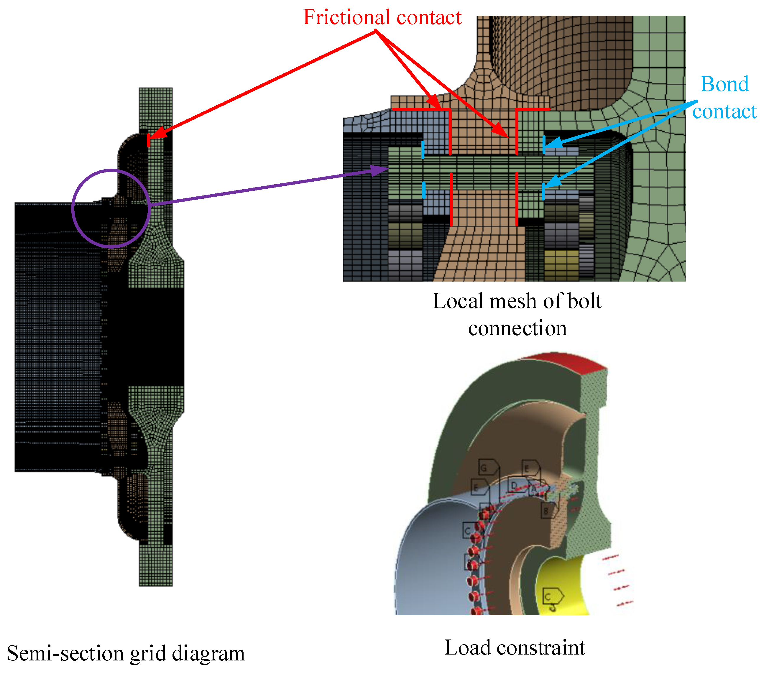
Figure 2 depicts the finite element model of the turbine disc–drum combination structure meshed via hypermesh and analyzed using Ansys Workbench. The unit used in this analysis is solid185. In hypermesh software, the turbine disc, grate disc, drum cylinder shaft, and bolts are respectively sliced to meet the conditions of mapping mesh division. Then, the mesh density near the bolt holes and the combination surface is controlled to ensure the mesh quality in the key areas. Finally, the disc–drum combination structure is divided into a hexahedral structured mesh model. The number of cells in this model is 751,200, the number of nodes is 973,075, and the average mesh quality is 0.75, which can meet the requirements of solution accuracy.
Due to the deformation incoordination phenomenon that is prone to occur in the rotor stop, it is not possible to simulate the fit between the turbine disc, the grate disc, and the drum and cylinder shaft by binding the contact. To establish contact pairs between the mating surface end face and the stop ring face, Target170 and Contact174 element types are utilized. An interference amount of 0.02 mm is applied to simulate the stop interference assembly between the components. The coefficient of friction contact is set to 0.2, and the remaining contact surfaces are treated as linear bound contacts. The contact characteristics are resolved using the augmented Lagrangian algorithm. It is divided into two load steps. The first step is to load F = 20 kN preload, a total of 48 bolts, and simulate the assembly stage. In the second step, the pre-tightening force is locked, the F1= 200 KN axial tension force is applied at the edge of the disc, and the rotational speed r = 18,800 rpm is applied to the overall structure to express the centrifugal force of the component, which is used to simulate the service stage. To be consistent with the actual working conditions, a cylindrical coordinate system is established on the inner ring of the disc to constrain the axial and circumferential degrees of freedom of the inner ring of the disc and release the radial degrees of freedom.
Referring to the actual engine material, the main component material of the turbine disc–drum is GH4169, and the Poisson’s ratio is 0.3 at room temperature, but the Poisson’s ratio increases to 0.33 at 700 °C. Because the composite structure is located in the high-pressure turbine part of the engine rotor and carries high-temperature and high-pressure gas, Poisson’s ratio is set to 0.33. The material of bolts and other connectors is set to 1Cr11Ni2W2MoV, and the material parameters are shown in Table 1.

5. Analysis of the Modal Influence of the Pre-Tightening State on Disc–Drum Connection Assembly in the Service Stage

5.1. Pre-Tightening State Setting

The bolt number is shown in Figure 3. Four pre-tightening states are defined: (1) Pre-tightening state of 48 bolts: the pre-tightening force of 48 bolts is 20 kN. (2) No pre-tightening state in 1 sector: set the pre-tightening force in 1 sector bolt to 0 N, and the pre-tightening force of the other 36 bolts to 20,000 N. (3) No pre-tightening state in 1 and 3 sectors: the pre-tightening force of bolts in 1 and 3 sectors is 0 N, and the pre-tightening force of the other 24 bolts is 20 kN. (4) Pre-tightening state of 24 bolts: set the pre-tightening force of all even number bolts to 0 N and the other bolts to 20 kN.

5.2. Analysis of the Influence of the Preloading State on Structural Modal Characteristics

The first 30 natural frequencies of the disc–drum connection assembly under the preloading state are shown in Figure 4. The low-order natural frequency is less affected by the preloading state. The main reason is that the low-order performance is the overall deformation of the component, and the number of bolts is large. When the preload of some bolts is greatly reduced, the mating surface still maintains a high overall stiffness. However, there are some sensitive orders of natural frequency change in the middle and high order frequency. These orders of natural frequency are sensitive to the change in preload state.
At the 24th order mode, the natural frequency is 2008.9 Hz for 48 fully tightened bolts in a pre-tensioned state. When the pre-tensioned state is changed to 1 sector without pre-tensioning, the natural frequency decreases by 16.2 Hz. When the pre-tightening state is changed to 1 and 3 sectors without pre-tightening, the natural frequency decreases by 32.4 Hz.
The localized degradation of the preload state has a greater impact on the intrinsic frequency of the structure compared to uniform degradation. The sensitive frequencies and vibration shapes of the first 30 order modes are further extracted. As shown in Table 2, these sensitive modes are more sensitive to the preload state of the mating surfaces of the turbine disc–drum combination structure.
It can be seen from the mode shape diagram that the sensitive mode shapes are 24-order petal-shaped vibration of the drum edge and 27-order local torsional vibration of the labyrinth teeth plate. In summary, the most significant vibration mode of the rotor natural frequency reduction caused by the bolt preload state is usually the local mode shape related to the fit surface or the local vibration at the weak stiffness part.

6. Pre-Tightening State Diagnosis Method of the Fit Surface of Disc–Drum Connection Component in the Assembly Stage

6.1. Pre-Tightening State Setting

According to the actual engineering practice, the following pre-tightening state working conditions are established: (1) Pre-tightening state of 48 bolts: the pre-tightening force of 48 bolts is 20 kN. (2) No pre-tightening state in 1 and 3 sectors: the pre-tightening force of bolts in 1 and 3 sectors is 0 N, and the pre-tightening force of the other 24 bolts is 20 kN. (3) Pre-tightening state under 40% deviation: the pre-tightening force of 48 bolts randomly gained between 12 kN and 20 kN using the Monte Carlo method. Figure 5 shows the distribution value of 40% deviation of bolt preloading force, with an average value of 15,752 N.

6.2. Pre-Tightening State Diagnosis Based on Axial Tension Force-Sensitive Natural Frequency Offset Method

Only the axial tension force F = 200 kN is considered, and the centrifugal force is not considered. The remaining boundary conditions are consistent with the service state, which is used to simulate the axial tension force of the hydraulic cylinder actuator in the assembly stage. From the analysis of Figure 6, it can be observed that as the bolt preload deviation increases to 40%, the low-order intrinsic frequency of the structure decreases only slightly, suggesting that the preload deviation has little impact on the low-order modes of the structure. However, within the middle- and high-order intrinsic frequency ranges, some sensitive frequencies of the components experience a significant decrease due to the preload deviation, indicating that the preload deviation has a notable effect on the middle- and high-order modes of the disc–drum combination structure. These sensitive modes are further extracted, as shown in Table 3. Combined with the information in the figure and the data in the table, it can be observed that when the preload deviation is 40%, relative to the ideal state without preload deviation, the 26th-order natural frequency value of the disc–drum combination structure decreases from 1855.6 Hz to 1848.4 Hz, with the most significant decrease being 7.2 Hz. According to the vibration mode diagram in the table, it can be seen that the vibration modes caused by bolt pre-tightening deviation leading to a decrease in the natural frequency of the rotor mostly belong to local vibration modes and overall bending vibration modes related to the mating surface.
Therefore, first of all, we can create a high-precision finite element model of the disc–drum assembly. Through modal analysis, we can identify the sensitive natural frequency and modal shape affected by the preloading state. Subsequently, we can position the acceleration and vibration sensors based on the characteristics of the sensitive modal shape for modal test research in engineering practice. Finally, using the change in sensitive natural frequency as a reference, we can determine the preloading state of the disc–drum assembly during the assembly identification stage.

6.3. Pre-Tightening State Diagnosis Based on Modal Mode Step Method

Without considering the external load, the remaining boundary conditions are consistent with the service state, which is used to simulate the actual assembly process of the disc–drum composite structure. Considering that the bolt preloading state has a great influence on the local mode shapes of the structure, the local mode shapes are mostly distributed in the middle and high-frequency bands. Therefore, the 20- to 30-order modal shapes of the disc–drum composite structure under several preloading states are extracted for modal assurance criterion (MAC) analysis, as shown in Figure 7.
The MAC diagram uses the whole node set of the model to extract the vibration mode displacement data in the three directions of X/Y/Z, respectively, and perform the correlation analysis of different working conditions. The MAC introduced here defines the real number formula, and its mathematical expression is:
f M A C , i , j = φ i T φ j 2 φ i T φ i φ j T φ j
where i and j represent ideal tightening conditions and preload state deviation conditions, respectively, and φ is the vibration displacement data.
It can be seen from Figure 7a that when there is a pre-tightening state under deviation of 40%, compared with the pre-tightening state, the 22-order and 23-order have a sequential step phenomenon, and the 24-order and 25-order tend to have a modal step phenomenon. The MAC values of the two orders are decreasing. As the further pre-tightening state degrades, the stiffness loss increases and the modal step phenomenon occurs. It can be seen from Figure 7b that with the degradation of the preloading state when there is no pre-tightening in sectors 1 and 3, the 24-order modal shape of the disc–drum composite structure is highly correlated with the 26-order modal shape of the disc–drum composite structure under a pre-tightening state of 48 bolts, and the 26-order modal shape is highly correlated with the 24-order modal shape of the pre-tightening state of 48 bolts, that is, the modal step phenomenon occurs. At the same time, the modal step phenomenon also occurred in the 20 and 21 modal shapes.
In this paper, a preloading state diagnosis method based on the modal mode step method is proposed. This method can diagnose the preloading state of the periodic cyclic symmetric structure from the change in the mode shape. The main process is shown in Figure 8.

7. Conclusions

This paper focuses on the issues related to sudden changes in rotor dynamics and operational stability caused by the degradation of the bolt preload state in the aero-engine disc–drum combination structure. This paper also focuses on the high-pressure turbine disc–drum combination structure and investigates the impact of the preload state of the mating surfaces on the modal characteristics of the structure during the in-service and assembly stages. This study concludes the following:
(1)
The influence of the preload state on the low-order modes of the disc–drum joint assembly is not significant, and the maximum reduction in frequency does not exceed 5 Hz, while there is a sensitive order in the middle and high-order bands, and the intrinsic frequency in this mode is significantly affected by the preload state, and it shows a different degree of downward trend. There is more than a 30 Hz reduction in frequency. At the same time, the local degradation of the preload state has a greater influence on the intrinsic frequency of the structure than the uniform degradation. The modal vibration pattern is mainly the petal-type local vibration at the connection mating surface or the drum.
(2)
The feasibility of the preload state identification method for turbine disc–drum assemblies is analyzed using vibration theory. It considers that the tensile force will reduce the connection stiffness of the bonding surface within a relatively low interval range. Furthermore, it proposes a preload state identification method for the mounting edge based on the tensile force-natural frequency change method. The method is applicable for identifying the preload state of complex disc–drum combination structures with multiple bolts and connectors.
(3)
According to the perturbation theory and simulation analysis results, it was found that the change in the preloading state induces the modal step phenomenon in the middle and high orders of the disc–drum combination structure. Therefore, considering the modal vibration change, a method for identifying the preload state based on the modal vibration step characteristic of the disc–drum assembly is proposed. This method can serve as a basis and reference for the dynamic inspection and assembly technology of aero-engine rotors and their components.

Author Contributions

Conceptualization, H.W., L.J. and P.X.; methodology, Y.Z. and H.W.; software, S.W. and H.W.; formal analysis, H.W.; investigation, P.X.; resources, L.J.; data curation, S.W.; writing—original draft preparation, H.W.; writing—review and editing, S.W.; visualization, S.W.; supervision, L.J.; project administration, L.J.; funding acquisition, P.X. and L.J. All authors have read and agreed to the published version of the manuscript.

Funding

This research was funded by the National Natural Science Foundation of China, grant numbers 12272319 and U2241274.

Data Availability Statement

Data are contained within the article.

Conflicts of Interest

The authors declare no conflict of interest.

References

  1. Zhao, Y.; Yang, C.; Cai, L.; Shi, W.; Hong, Y. Stiffness and Damping Model of Bolted Joints with Uneven Surface Contact Pressure Distribution. J. Mech. Eng. 2016, 62, 665–677. [Google Scholar] [CrossRef]
  2. Zou, C.; Xia, H.; Chen, K.; Zhai, J.; Han, Q. Research on the identification method of the pre-tightening state of the matching surface of the aero-engine disk-drum rotor. Eng. Fail. Anal. 2022, 136, 106208. [Google Scholar] [CrossRef]
  3. Zhu, W.; Mei, B.; Ke, Y. Kinematic modeling and parameter identification of a new circumferential drilling machine for aircraft assembly. Int. J. Adv. Manuf. Technol. 2014, 72, 1143–1158. [Google Scholar] [CrossRef]
  4. Frangoudis, C.; Rashid, A.; Nicolescu, C.M. Development and analysis of a consciously designed Joint Interface Module for improvement of a machining system’s dynamic performance. Int. J. Adv. Manuf. Technol. 2017, 88, 507–518. [Google Scholar] [CrossRef]
  5. Schwingshackl, C.W.; Petrov, E.P. Modeling of Flange Joints for the Nonlinear Dynamic Analysis of Gas Turbine Engine Casings. J. Eng. Gas Turbines Power 2012, 134, 122504. [Google Scholar] [CrossRef]
  6. He, X.L.; She, T.L.; Xu, B.; Li, J.; Chen, G.; Cao, G.F. Method for detecting bolts looseness of a wind turbine tower based on its vibration characteristics. J. Vib. Shock. 2016, 35, 112–118. [Google Scholar] [CrossRef]
  7. Qin, Z.; Han, Q.; Chu, F. Bolt loosening at rotating joint interface and its influence on rotor dynamics. Eng. Fail. Anal. 2016, 56, 456–466. [Google Scholar] [CrossRef]
  8. He, K.; Zhu, W.D. Detecting Loosening of Bolted Connections in a Pipeline Using Changes in Natural Frequencies. J. Vib. Acoust. 2014, 136, 034503. [Google Scholar] [CrossRef]
  9. Shuguo, L.; Yanhong, M.; Dayi, Z.; Jie, H. Studies on dynamic characteristics of the joint in the aero-engine rotor system. Mech. Syst. Signal Process. 2012, 29, 120–136. [Google Scholar] [CrossRef]
  10. Liu, Y.; Zhao, D.; Guo, X.; Ai, Y. Stiffness and geometry characteristics of flange connection with bolt failure and its influence on rotor dynamics. Proc. Inst. Mech. Eng. Part C J. Mech. Eng. Sci. 2023, 237, 095440622211474. [Google Scholar] [CrossRef]
  11. Zhao, L.; Zhang, H.; Shen, P.; Liu, Y. Nonlinear Dynamic Characteristics of Rod Fastening Rotor with Preload Relaxation. Energies 2022, 15, 1052. [Google Scholar] [CrossRef]
  12. Beaudoin, M.-A.; Behdinan, K. Analytical lump model for the nonlinear dynamic response of bolted flanges in aero-engine casings. Mech. Syst. Signal Process. 2019, 115, 14–28. [Google Scholar] [CrossRef]
  13. Zhang, J.; Du, M.; Shao, Y.; Chen, J. Simulation on Loosening Behavior of Threaded Fastener under Transverse Vibration. Int. Conf. Mechatron. Autom. 2015, 8, 1886–1890. [Google Scholar]
  14. Tol, S.; Özgüven, H.N. Dynamic characterization of bolted joints using FRF decoupling and optimization. Mech. Syst. Signal Process. 2015, 54, 124–138. [Google Scholar] [CrossRef]
  15. Balaji, N.N.; Chen, W.; Brake, M.R.W. Traction-based multi-scale nonlinear dynamic modeling of bolted joints: Formulation, application, and trends in micro-scale interface evolution. Mech. Syst. Signal Process. 2020, 139, 106615. [Google Scholar] [CrossRef]
  16. Sohn, H.; Farrar, C.R.; Hemez, F.M.; Czarnecki, J.J. A Review of Structural Health Monitoring Literature: 1996–2001; Los Almos LA-13976-MS: Los Alamos, NM, USA, 2004. [Google Scholar]
  17. Montalvao, D.; Ribeiro, A.M.R. A Review of Vibration-based Structural Health Monitoring with Special Emphasis on Composite Materials. Shock. Vib. Dig. 2006, 38, 295–324. [Google Scholar] [CrossRef]
  18. Nguyen, T.-T.; Ta, Q.-B.; Ho, D.-D.; Kim, J.-T.; Huynh, T.-C. A method for automated bolt-loosening monitoring and assessment using impedance technique and deep learning. Dev. Built Environ. 2023, 14, 100122. [Google Scholar] [CrossRef]
  19. Tao, T.; Mingjun, H.; Xie, J.; Yuxiang, Z.; Xin, Z. Research on Improved damage index for evaluating bolt looseness of flange structures. J. Beijing Univ. Aeronaut. Astronaut. 2021, 47, 123–131. [Google Scholar]
  20. Yue, C.; Chi, H.; Fan, J.; Zheng, X.; Zhang, Z. Prediction of bolt missing fault for multistage rotor by experimental test and analysis. Int. J. Adv. Manuf. Technol. 2023, 124, 4551–4562. [Google Scholar] [CrossRef]
  21. Tao, G.; Jianhua, Y.; Miguel, A.F.S.; Houguang, L. Adaptive Stochastic Resonance for Bolt Looseness Identification under Strong Noise Background. J. Comput. Nonlinear Dyn. 2022, 17, 071003. [Google Scholar]
  22. Wang, H.; Xue, P. Investigation of the Uncoordinated Bolt Deformation of a Disc–Drum Combined Structure in a Turbine under Various Operating Conditions. Machines 2023, 11, 661. [Google Scholar] [CrossRef]
  23. Huda, F.B.; Kajiwara, I.; Hosoya, N.K.; Kawamura, S. Bolt loosening analysis and diagnosis by non-contact laser excitation vibration tests. Mech. Syst. Signal Process. 2013, 40, 589–604. [Google Scholar] [CrossRef]
  24. Hofmeyer, H.; Courage, J. Analytical and finite element modelling of long plate mode jumping behaviour. Thin-Walled Struct. 2013, 73, 101–111. [Google Scholar] [CrossRef]
Figure 1. High-pressure turbine disc–drum composite structure and its stress condition in the tight state. 1—drum shaft, 2—labyrinth teeth plate, 3—high-pressure turbine disc.
Machines 12 00083 g001
Figure 2. Finite element model of high-pressure turbine disc–drum combined structure.
Machines 12 00083 g002
Figure 3. Bolt number.
Machines 12 00083 g003
Figure 4. The influence of the pre-tightening state on the natural frequency of the disc–drum connection component. (a) Comparison of frequencies under different preloading states, (b) the difference in frequency in different preloading states.
Machines 12 00083 g004
Figure 5. Distribution of 40% deviation of preloading force.
Machines 12 00083 g005
Figure 6. Comparison of natural frequencies under different preloading states.
Machines 12 00083 g006
Figure 7. MAC diagram of disc–drum composite structure with different preloading forces. (a) Tightening preloading state and deviation preloading state. (b) Pre-tightening state and no pre-tightening state of 1 and 3 sectors.
Machines 12 00083 g007
Figure 8. Pre-tightening state diagnosis method based on modal mode step method.
Machines 12 00083 g008
Table 1. Material parameter table.
MaterialDensityYoung’s ModulusPoisson’s Ratio
GH41698240 kg/m31.99 × 10^5 MPa0.33
1Cr11Ni2W2MoV7850 kg/m32.00 × 10^5 MPa0.30
Table 2. Sensitive order mode of the disc–drum connection assembly under ideal preload state in service.
Rank2427
Natural frequency/Hz2008.92471.6
Mode shapeMachines 12 00083 i001Machines 12 00083 i002
Mode shape descriptionPetal-shaped vibration of the drum edgeLocal torsional vibration of the labyrinth teeth plate
Table 3. Sensitive modes of the disc–drum connection assembly under axial tension force in the ideal preloading state.
Order16-Order24-Order26-Order30-Order
natural frequency/Hz1473.41795.81855.61940.3
mode vibration shapeMachines 12 00083 i003Machines 12 00083 i004Machines 12 00083 i005Machines 12 00083 i006
Mode shape descriptionBending vibration dominated by labyrinth teeth plate and turbine diskPetal-shaped vibration of the drum edgeLocal torsional vibration of the labyrinth teeth plateLocal axial swing of labyrinth teeth plate
Disclaimer/Publisher’s Note: The statements, opinions and data contained in all publications are solely those of the individual author(s) and contributor(s) and not of MDPI and/or the editor(s). MDPI and/or the editor(s) disclaim responsibility for any injury to people or property resulting from any ideas, methods, instructions or products referred to in the content.

