Article

Experimental Analysis of Rolling Torque and Thermal Inlet Shear Heating in Tapered Roller Bearings

by
Manjunath Manjunath
1,*,
Dieter Fauconnier
1,2,
Wouter Ost
1,2 and
Patrick De Baets
1,2,3
1
Soete Laboratory, Department of Electromechanical, Systems & Metal Engineering, Faculty of Engineering and Architecture, Ghent University, Technologiepark 903, 9052 Ghent, Belgium
2
Flanders Make @ UGent-Core Lab MIRO, 9000 Ghent, Belgium
3
Royal Institute of Technology KTH, Systems and Component Design, School of Electrical Engineering and Computer Science, Lindstedtsvägen 3, 100 44 Stockholm, Sweden
*
Author to whom correspondence should be addressed.
Machines 2023, 11(8), 801; https://doi.org/10.3390/machines11080801
Submission received: 10 July 2023 / Revised: 28 July 2023 / Accepted: 31 July 2023 / Published: 3 August 2023
(This article belongs to the Special Issue Friction and Lubrication of Rolling Element Bearings)

Abstract

:
The investigation in this article focuses on the rolling resistance torque and thermal inlet shear factor in tapered roller bearings (TRBs) through systematic experiments using a modular test setup. TRBs typically operate under Elastohydrodynamic Lubrication (EHL) conditions. At sufficiently high speeds, the majority of rolling friction is due to a significant shift of the pressure centre in the EHL contact. While at lower speeds, sliding friction in the roller-rib contact becomes dominant, which operates under mixed lubrication conditions. Limited literature exists on the impact of inlet shear heating on effective lubricant temperature ( T i n _ c ) and rolling friction in TRBs. To fill this gap, experimental measurements of the total frictional torque under axial loading at different speeds and oil temperatures are performed. With existing models for different friction contributions described in the literature, the rolling resistance due to EHL has been determined for various operating conditions. The effects of dimension-less speed (U), material (G), and load (W) parameters have also been investigated. Under fully flooded conditions, it was observed that the influence of material (G) and load (W) parameters on rolling friction is minor, while the impact of velocity (U) is significant. In the context of rolling resistance, the heating due to shear of the lubricant in the inlet zone plays a significant role. For higher rotational velocities, the estimated rotational torque reduction resulting from inlet shear heating was found to be approximately 6–8%.

1. Introduction

Modern heavy-duty drivetrains and industrial machinery benefit from high-power density. Often, tapered roller bearings (TRBs) are preferred for their high load capacity and rigidity. However, TRBs experience higher frictional losses due to additional contact between conical rollers and the raceway rib, reducing efficiency and causing increased power losses at higher speeds and loads in mixed lubrication conditions. Adequate lubrication ensures energy-efficient and durable TRB operation under varying velocities, loads, and temperatures.
Ideally, bearings operate in an Elasto-Hydrodynamic Lubrication (EHL) regime [1,2,3], with contact surfaces fully separated by a thin layer (about 50 nm to 1 μm thick) of pressurized lubricant film, enabling efficient load transmission. Under mixed lubrication conditions, e.g., lower speed-to-load ratio or lower lubricant viscosity, direct metallic asperity contact occurs, leading to higher friction and higher risk of damage and wear [4,5,6,7,8,9,10,11].
The friction generated in TRBs is composed into load-dependent and load-independent contributions (Figure 1a). The load-dependent frictional torque includes (a) The bearing torque due to tractive rolling of the rollers on the raceways M r r ; and (b) The sliding torque due to the contact between the rib and the roller faces M s l _ r i b . M r r originates from elastic hysteresis losses in the loading and unloading of the solid material and the viscous rolling resistance due to the lubricant film viscous dissipation [12,13,14]. The latter is typically much larger than the former for oil lubrication [12]. On the other hand, M s l _ r i b consists of both viscous and Coulombic contributions. The load-independent contributions are governed by (c) The cage friction M c a g e ; and (d) The viscous drag losses M d r a g . At intermediate speeds, the load-independent contributions are relatively small [12] (Figures 11b and 13b). Hence, the load-dependent raceways and rib are essential for the analysis.
Ideally, EHL prevails in the roller-raceway contacts. The rolling resistance is due to viscous shear stresses in the deforming contact geometry and inlet region. For very high entrainment velocities and, particularly, high slide-to-roll ratios, the oil close to the contact area is repelled and produces a recirculating flow. This flow is accompanied by viscous shear heating leading to the so-called thermal inlet shear effect (Figure 1b), which raises the oil temperature ( T i n _ c ) at the entry of the contact area and, hence, reduces the oil viscosity, the film thickness, and, finally, the M r r [15]. Therefore, a thorough understanding of the thermal inlet shear effect on M r r is needed for different operating conditions of TRBs.

1.1. State of the Art

In the past 50 years, many authors analytically derived and experimentally validated equations for predicting load-dependent frictional loss in TRBs [16,17]. Very few authors derived the viscous rolling resistance in roller-raceway contact of TRBs using the dimensionless velocity (U), load (W), and material (G) parameters (Equation (1)). They are presented in Table 1.
U = η o μ r E R e   ;   W = w l   E R e   ;   G = α E
In 1987, Aihara [12] derived an analytical formula for the load-dependent frictional torque in TRBs operating under pure axial external loads. The formula accounts for rolling resistance at the raceway and friction at the rib-roller contact, with modifications based on the work of Murch and Wilson [18] (see Appendix A, Table A1) and a wide range (L = 0 to 5000; Equation (2)) of the non-dimensional thermal loading parameter [19,20]. This parameter characterizes heat generation within the lubricating film and provides valuable insights into the lubricant’s thermal behavior and its impact on EHL contact performance and reliability. The formula for rib sliding friction was derived based on Patir and Cheng [21] (see Appendix A, Table A1) by focusing on the asperity load, oil film–surface roughness ratio, and a partial EHL model. Experimental validation under various conditions (see Table 1) showed that the rolling resistance in TRBs had minimal dependence on the axial load, but the specific sources of traction forces and moments contributing to the TRB’s resistance torque remain unclear. In 1991, Zhou and Hoepprich [13] developed an analytical torque model for TRBs, using a single contact load distribution. Their model accurately predicted torque components by balancing forces and moments, shedding light on the sources of torque and heat generation. They obtained the rolling resistance equation through numerical solutions for lubricant film thickness and pressure distribution in an isothermal EHL line contact, considering the Reynolds equation and viscosity–pressure relationship. Through power fitting, they determined functions for rolling resistance forces during pure rolling. They also derived an equation for rib sliding friction by numerically solving the lubricant film thickness equation for an elliptical contact, considering rib roller surface roughness. Bair and Winer’s [22] (see Appendix A, Table A1) rheological model for EHL lubricant shearing was also employed. Experiments were conducted using different oils and load conditions to measure the torque of the raceway and rib separately (see Table 1). The study highlighted the importance of the rib-roller end contact torque for low Lambda (1 to 2; film thickness-to-surface roughness ratio) values and the significant impact of thermal effects in predicting torque for high-speed bearing applications. The experimental and calculated results aligned well when incorporating the thermal reduction factor. This research is noteworthy for considering thermal effects and surface roughness in rib-roller torque calculations.
L = η o β o μ r 2 k
Between 1998 and 2001, H. Matsuyama [14,23,24] proposed a torque model for TRBs by numerically solving the Reynolds equation in conjunction with Roelands’ equation (see Appendix A, Table A1) and the Dowson–Higginson equation. This model enables the calculation of viscous rolling resistance in TRBs. A simplified formula for viscous rolling resistance under fully flooded conditions was obtained by conducting full numerical EHL calculations. The equation for the rib sliding friction was determined by measuring the moment ( m r ) at the rib contact. A comparison between the measured torque (see Table 1) and a simplified formula derived from theoretical analysis revealed differences in the exponents of certain variables. Adjustments were made to these exponents to align them with the theoretical values. In 2002, Houpert [25] formulated analytical equations for forces and moments based on the TRB geometry. The rolling friction model proposed by Zhou and Hoeprich [13] was utilized, and an equation for the rib normal force ( F r ) was derived based on the rib geometry and Hertzian contact width. The friction coefficient of TRBs, which is dependent on the dimensionless film thickness parameter λ, was calculated. They employed experimental data (see Table 1) from Mircea Gradu (2000) [26], which exhibited a good agreement between measured and calculated torque. From 2003–2004, SKF bearing catalogue [15] presented a computational mode incorporating starvation and inlet shear heating effects for calculating rolling frictional moments. The model also considers the sliding friction coefficient for full-film, mixed lubrication conditions, which is applicable to oil and grease-lubricated bearings. This frictional torque (Mt) calculation method is accounting for rolling friction (a) and sliding friction (b), seal friction (c), drag (d), and seal loss based on the experimental results.
Table 1. TRBs frictional losses composition models.
AuthorEquationsApplicability Range
Aihara, 1987 [12] M i , o = 1.76 e 2 1 + 029 L 0.78 1 α   ( G U ) 0.658 W 0.31 R e 2 l The equations were experimentally validated under conditions:
Axial load ∈ [0.45 to 1.2 GPa]
Rolling speed ∈ [100 to 3000 rpm]
Oil type ∈ [Gear oil (80 W)]
Oil temperature ∈ [50 to 80 °C]
Lubricated condition ∈ [Fully flooded]
M s l _ r i b =   e µ r i b F a e x p 1.8 λ r 1.2
Zhou and Hoepprich, 1991 [13] M i , o = φ i s h φ b l 58.4 R e 2 α   ( G U ) 0.648 W 0.246 l The equations were experimentally validated under conditions:
Axial load ∈ [0.85 to 1.47 GPa]
Rolling speed ∈ [100 to 8000 rpm]
Oil type ∈ [SAE20, Vactra oil]
Oil temperature ∈ [50 °C]
Lubricated condition ∈ [Fully flooded]
M s l _ r i b = c , S o σ o F r e x p B λ r + φ T ,   r i b τ ( x , y ) d x d y  
H. Matsuyama (1998–2001) [14,23,24] M i / o = φ i s h 14.2 E l R e 2 U 0.75 G 0.04 W 0.08 The equations were experimentally validated under conditions:
Axial load ∈ [0.3 to 1.3 GPa]
Rolling speed ∈ [100 to 1500 rpm]
Oil type ∈ [Paraffin-based, traction oil]
Oil temperature ∈ [26 °C]
Lubricated condition ∈ [Fully flooded]
M s l _ r i b = e R o m r D a ( R i + l 2 sin α i e cos θ ) M s l _ r i b =   e µ r i b F a c o s γ µ r i b = c 1 e x p ( c 2 λ r c 3 + c 4 )
Houpert 2002 [25] M i / o = 0.04 E l R e 2 U 0.44 W 0.37   The equations were experimentally validated under conditions:
Axial load ∈ [3500 N]
Radial load ∈ [4250 N]
Rolling speed ∈ [100 to 4500 rpm]
Oil type ∈ [ATF oil]
Oil temperature ∈ [50 °C]
Lubricated condition ∈ [Fully flooded]
M s l _ r i b = µ r i b F r e 1 + 0.18 b e 2  
SKF 2003–2004 [15] M i / o = φ i s h φ r s G r r ( η o n ) 0.6 The equations were validated for all types of roller bearings and are applicable to both grease- and oil-lubricated bearings under constant loads in magnitude and direction.
M s l _ r i b = G s l φ b l μ b l + 1 φ b l μ E H L
Where i, o, and f correspond to inner raceways, outer raceways, and flange contacts.
In 2018, Schwarz et al. [27] experimentally studied TRB’s frictional torque and temperature, focusing on finding a minimal oil flow rate to achieve non-starved lubrication. Results showed that a small amount of oil could be sufficient for TRBs to operate safely and stably. The direction of oil supply was observed to have a significant impact on friction, with oil supply opposite to the pumping direction reducing frictional losses by minimizing hydraulic losses. To understand the TRB rib-roller contact, Wirsching et al. [17] (2021) studied its tribological behaviour as a function of different macro-geometries using machine-learning techniques. The geometric parameters describing the roller end-face and rib geometry were sampled by a statistical design of experiments. Their study demonstrated a trade-off between high load-carrying capacity and low friction losses exists. TRBs operating at low axial loads and/or sufficiently high velocities combine a moderate risk of wear and a minimised energy loss. Liu et al. (2022) [28] studied how roller geometric homogeneity affects TRB friction torque. They developed a mathematical model considering dimensional and shape deviations among rollers, simulating machining-induced geometric variations using Gaussian-distributed diameter deviation. Results showed that overall friction torque on raceways was minimally affected by roller homogeneity but significantly impacted sliding friction between individual rollers and inner raceway. Diameter deviation was crucial in determining maximum sliding friction, especially under light loads. Liu et al. (2023) [29] developed a thermal EHL (TEHL) model using a shear-thinning fluid (Carreau model) to analyze TRB geometries. They compared two rib geometries: tapered and spherical, for their coefficient-of-friction (COF) variations. The TEHL contact’s film thickness and temperature increased with the inner raceway’s velocity. The tapered rib had a nearly constant difference between minimum and central film thickness, while the spherical rib exhibited lower COF and minimum film thickness due to its higher film temperature.

1.2. Goal of the Paper

In the literature discussed above, the analyses of rolling and sliding frictional torques were focused towards the dimensionless load ( W ) and speed ( U ) parameters used in EHL, along with the effects of the geometrical influence of the rib-roller contact. However, the effect of inlet shear heating on the effective lubricant temperature ( T i n _ c ). Hence, the rolling friction in TRBs and the corresponding torque are rarely reported in the literature. In this work, experiments have been conducted to determine the load-dependent frictional losses in an axially loaded TRB as a function of the external axial load, speed, and supply oil temperature under fully flooded lubrication conditions. The literature models presented in Table 1 are compared to the experimental results and used to unravel the different friction contributions. Furthermore, the influence of shear heating at the inlet of the EHL contacts on the rolling friction, as well as on the bearing outer race temperature, are investigated at different operating conditions. Additionally, systematic experiments are conducted to find the optimal oil flow rate for the oil circulation lubrication system.

2. Materials and Methods

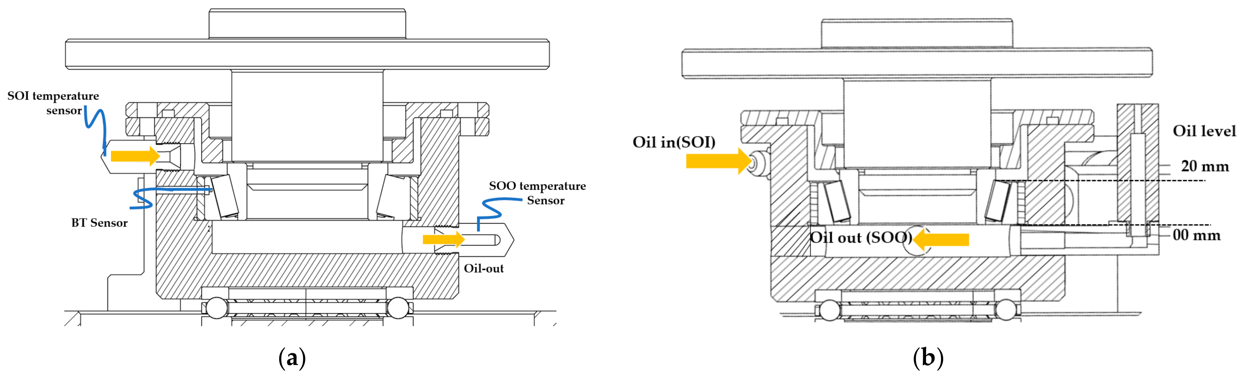
2.1. Experimental Setup

The experimental setup used in this work is a vertical-shaft roller-bearing tribometer (RBT) capable of accommodating bearings with inner diameters of 35–60 mm. It comprises six sub-systems: the drive unit, support-bearing unit, test-bearing unit, hydraulic loading unit, oil circulation unit, and control unit. The hydraulic cylinder has a load capacity of 45 kN (Table 2).
Figure 2 shows a cross-sectional view of the RBT. The main shaft (1) is supported by a cylindrical roller bearing (2) and two angular contact ball bearings (3) and is driven by an AC motor. The testing unit comprises a test-bearing adapter (4) and a test-bearing housing (5). A hydraulic cylinder is used to apply the axial load on the test bearing. Firstly, the complete test bearing unit is raised and aligned with the rotating shaft using a cylinder piston stroke. Once assembled, the desired test load is applied to the test bearings. The test bearing is assembled inside the test cup with the assistance of a bearing holder. At the bottom, a thrust ball bearing supports the test-bearing cup.
The frictional torque is measured using a lever arm (6) attached to the bearing housing. A load cell is mounted on the arm between the test-bearing housing and the thrust-bearing housing to measure the tangential frictional force while excluding the shaft support-bearing influence. A 300 N or 500 N load cell is used depending on the expected friction force and measurement accuracy [30]. The friction measurements of the test bearing are not significantly affected by the bottom support thrust bearing under standing-still conditions.
The RBT allows for the use of forced circulation (Figure 3a), as well as oil bath lubrication (Figure 3b). The lubricant flow rate and temperature are properly monitored and controlled. By controlling the oil flow rate into the bearing cup, as well as controlling the oil outlet from the bearing cup through a scavenging system, the oil level inside the test bearing cup can be adjusted (Figure 3b).
In this work, the bearing setup is employed to investigate the heavily loaded EHL line contacts (2–3 GPa) of TRBs under a purely axial load and well-controlled fully flooded lubricant conditions (Figure 3a). The pure axial loading of the TRB ensures equal contact conditions for all rollers in the bearing. Thermocouples have been installed in the supply oil inlet (SOI) and supply oil outlet (SOO), as well as in the TRB outrace temperature (BT). All measuring signals are registered continuously using digital data acquisition.

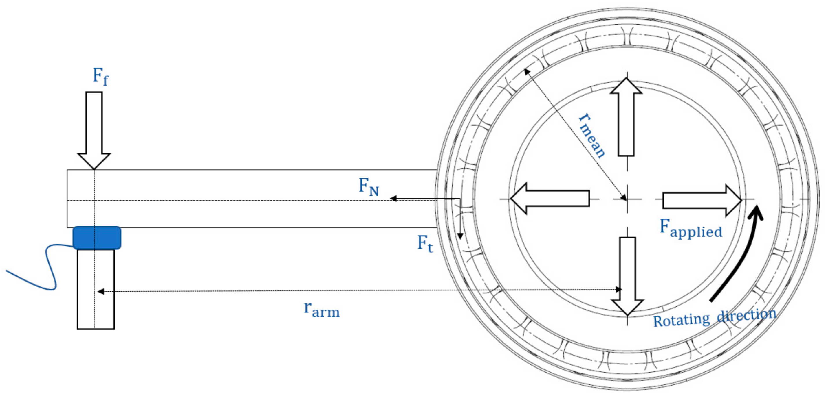
2.2. Test-Bearing Geometry and Forces

In this research, a single-row TRB with an inner diameter of 40 mm, outer diameter of 68 mm, and width of 19 mm is used (Figure 4). When a pure axial load ( F a ) is applied to a TRB, three distinct loads act on each roller, as shown in Figure 4. These three loads are the roller end and rib force ( F r ), and the outer raceway load ( F o ) that is almost the same as the inner raceway load ( F i ). Each load may be expressed as follows, with Z the number of rollers [12]:
F i =   F a Z s i n α i   ;   F o =   F a Z s i n α o         ;   F r =   F a s i n 2 γ Z s i n α o
Figure 5a,b provide an overview of all sliding friction forces and moments that occur in TRB contacts. However, it is important to note that the analysis does not consider the spin moment in the rib, cage-to-cage friction, and churning resistances.
From the balance of forces and moments on one single roller, the following equations [12,13,14,23,24,25,31] are obtained,
F s o F s i = F s f        
M i + M o = D a 2 F s o + D a 2 F s i + D a 2 e F s f
By combing Equations (4) and (5), F s o , F s i can be eliminated, leaving M i   M o , and F s f (detailed derivation in Appendix B). The torque of TRB is defined as the moment acting on the outer ring (M).
M = Z ( R o F s o M o )
M =   Z 1 D a R o M i + R i M o + Z R o D a e F s f = M r r + M s l _ r i b
Equation (6) encompasses the rolling resistance torque ( M r r ) and sliding rib torque ( M s l _ r i b ). M i and M o in Equation (7) consist of the EHL viscous rolling resistance and elastic hysteresis. However, with oil lubrication, the effect of elastic hysteresis is much smaller than that of viscous resistance [12,13,14]. Before delving further, it is essential to discuss the rolling resistance ( M i / o ). The rollers are supposed to “roll” along the raceways. Still, some slippage exists in the roller-raceway contact areas, which causes sliding friction or traction, as shown in Figure 5. This sliding friction is determined by the moments ( M i / o ) and the sliding friction between the roller ends and rib   F s f [12].

2.2.1. Theoretical Analysis of Viscous Rolling Resistance ( M i , M o )

Ideally, the contacts between the rollers and the raceways operate in EHL, and the rolling friction is governed by viscous shearing at the inlet and in the pressurized zone. As shown in Figure 6, the asymmetry of the pressure distribution in the EHL contacts induces a moment on the roller that counteracts the rolling motion, as the center of pressure is displaced from the center of Hertzian contacts [14]. The coordinate x c p of the center of pressure is provided by:
x c p = 1 w x L 1 x L 2 p ( x ) x d x
The moment due to w acting on the coordinate x c p is equivalent to the moment due to the EHL pressure distribution. The viscous rolling resistance ( M i / o ) is provided as follows [14,23,24]:
M i / o = 0 l x c p w d y = x c p w l
where l is the effective length of the roller.
The dimensionless coordinate of the center of pressure, X c p is expressed from Equation (9) as follows:
X c p = x c p b = 2 π X L 1 X L 2 P X d X
Thus, the dimensionless viscous rolling resistance ( m i / o ) is provided as the following equation:
m i / o = M i / o b E l R = X c p W
When the pressure distribution is obtained from EHL analysis, the dimensionless viscous rolling resistance ( m i / o ) is estimated using Equations (10) and (11). The numerical EHL analysis of Matsuyama [14,23] is used to obtain m i / o and demonstrate the influence of dimensionless parameters U, G, and W on m i / o under fully flooded conditions.
m i / o = 8.89 U i / o 0.75 G i / o 0.04 W i / o 0.42
From Equations (11) and (12), a simplified formula for viscous rolling resistance ( M i / o ) under fully flooded conditions is provided by the following [14,23]:
m i / o = M i / o b E l R = 8.89 U i / o 0.75 G i / o 0.04 W i / o 0.42
With
b = R 8 W π
M i / o = 14.2 E l R e 2 U i / o 0.75 G i / o 0.04 W i / o 0.08
Rolling resistance torque ( M r r ) can be predicted by the following Equation (14), which is obtained by substituting ( M i / o ) in Equation (6) [14,23].
M r r = Z D a R o · 14 · 2 E l R e 2 U i 0.75 G i 0.04 W i 0.08 + R i · 14 · 2 E l R e 2 U o 0.75 G o 0.04 W o 0.08
M r r is estimated using dimensionless speed (U), load (W), and material (G) parameters with the help of the available EHL rolling frictional model (Table 1).

2.2.2. Sliding Friction in Roller End and Rib Contacts ( M s l _ r i b )

The second term in Equation (7) represents the force resulting from the sliding between the roller end and the rib. By introducing a coefficient of friction μ r i b , F s f can be expressed as µ F r . Here, F r is the force against the rib, as shown in Figure 4. For a purely axial load (Fa), F r is given by Equation (3) and M s l _ r i b can be rewritten as follows (detailed derivation in Appendix C):
M s l _ r i b =   e μ r i b cos γ F a ;   U s u a l l y ,   γ   v e r y   s m a l l   s o   cos γ = 1
M s l _ r i b =   e μ r i b F a
The frictional torque contribution of the rib M r i b was experimentally measured using a special loose rib [13,14]. The ribs were deliberately separated from the inner ring in order to isolate and measure the frictional torque, specifically generated at the rib. The authors reported that the sliding friction on the rib is at its maximum value when at a starting rotation from a standstill and decreases rapidly with the rotational speed due to the formation of a thin lubricant film (Figure 7a). SKF has simplified the sliding friction coefficient for both full-film and mixed lubrication conditions (Figure 7b). The calculated sliding friction based on the SKF model exhibits a similar trend to the experimentally measured values by Zhou [13].
μ r i b = φ b l μ b l + ( 1 φ b l ) μ E H L
φ b l = 1 e x 2.6 · 10 8 ( n η o ) 1.4 d m

2.3. Frictional Measurements Using RBT Setup

The configuration for measuring the global frictional force is depicted in Figure 8 where r a r m represents the horizontal distance between the points of action of F a p p l i e d and F f . R m e a n denotes the mean radius of the bearing. During the tests, the hydraulic actuator applies a normal constant axial load Faxial (Figure 2). The TRB torque can be measured by the reaction force of the floating bearing housing, where the thrust-bearing friction has relatively minimal friction. The deviation of the piston load from its vertical position is assumed to be very small. Internally in the test-bearing chamber, a reaction force per roller occurs that can be decomposed in a normal component FN, and a tangential component Ft. The tangential component results from viscous friction between inner and outer raceway contacts, including side rib torque. As both Ft and FN cannot be measured directly, they have to be derived from the applied Fapplied and frictional forces Ff from the vertical and horizontal force balance equation.
M t = F f · r a r m = F t · r m e a n
Rearranging Equation (18) for tangential force provides
F t = F f · r a r m r m e a n      
In this manner, the global torque ( M t ) of TRBs is measured for different operating conditions. To minimize the drag loss in the global measurements, systematic experiments were conducted to find the optimum oil-flow rate for the oil-circulation lubrication method. The corresponding drag losses are verified to be minimal using models from the literature [33,34] (detailed in Section 4.1). Since the global friction ( M t ) of test TRB is being measured, it primarily consists of the significant contributions from rolling-resistance torque ( M r r ) and rib torque ( M s l _ r i b ) while minimizing drag losses.
M t   M r r + M s l _ r i b  
Using the SKF model (Equations (15)–(17)), the frictional torque of the rib-roller contact ( M s l _ r i b ) is computed at the same experimental operating conditions and subtracted from the measured total frictional torque M t (Equation (20)).
M r r M t M s l r i b
The value of M r r , reconstructed from the measurements using Equation (21) is compared to the models of Aihara, Zhou, and Matsuyama in Section 4.3 for a wide range of dimensionless load and speed parameters.

2.4. Importance of Thermal Reduction Factor on Raceway Friction Prediction

At very high entrainment speeds, especially for non-zero values of the SRR, the lubricant in the contact inlet becomes heated ( T i n _ c ), leading to a reduction of its viscosity and film thickness and, consequently, the flow rate of the entrained lubricant. In TRB with low lubricant viscosity and surface velocity, the thermal loading parameter L is sufficiently small (L = 0.1 in Equation (2)) for thermal effects to be negligible in inlet heating. In this case, conventional isothermal theory can be used. However, with high-speed and/or high-viscosity lubricants (L greater than 0.1), inlet heating can substantially reduce the film thickness and rolling friction [35]. Hence, the film thickness, as well as the rolling torque, depend significantly on the properties of the lubricant in the inlet region ( T i n _ c ). Matsuyama [14] incorporated the shear heating correction φ T [ 0 ,   1 ] into the calculation of the rolling torque M r r as
M r r = φ T   · 14 · 2 E l R e 2 U i 0.75 G i 0.04 W i 0.08 R o + 14 · 2 E l R e 2 U o 0.75 G o 0.04 W o 0.08 R i
For φ T = 1 , isothermal conditions prevail, whereas for φ T < 1 , thermal effects become increasingly more important. In this work, the shear heating correction φ T is determined experimentally from the measured rolling torque M r r using Equation (22).

3. Design of Experiments and Methodology

The following Algorithm 1, provides an overview of the experimental workflow. Prior to the experiments, a continuous run-in procedure had been performed [36], running the TRB at 10 different speeds increasing from 220 rpm to 2200 rpm, each for 1 h to get smooth (polish) raceways. During the run-in, a constant oil flow rate of 0.5 lpm was supplied to the TRB at a constant temperature of 30   . All experimental test series are conducted after run-in period.
Algorithm 1. Procedure for thermal inlet study.
  Conduct run-in procedure
  Experiments to determine the optimal flow rate to minimize drag, i.e., M d r a g M t   for   W 0
  Experiments for all U, G & W:
                Measure the total torque M t
              Calculate M s l r i b using (Equations (15)–(17))
              Calculate M r r M t M s l r i b (Equation (21))
              Calculate thermal inlet shear heating factor φ T = φ T ( M r r , U , W , G ) (Equation (22))
Result: Thermal inlet shear heating, φ T , effect on raceway torque
Experiments were conducted to determine the optimal flow rate for minimizing drag in TRBs. The measurements involved varying flow rates (0.2 lpm to 0.5 lpm) and speeds (500 rpm to 2000 rpm) while keeping the load constant and controlling the oil supply temperature at 30 °C. Each test had a duration of 1 h, allowing for thermal equilibrium and steady-state frictional torques to be achieved. Experiments were carried out to investigate the effect of dimensionless velocity (U) and material (G) parameters on rolling re-resisting torque and thermal inlet shear effect of TRBs under different temperatures and speeds.
The specifications of the test TRB are explained in Section 2.2. Experiments are conducted to measure frictional torque and temperature within the supply oil temperature range from 35 °C to 65 °C (due to the limited value of α ), speed from 200 rpm to 2200 rpm, and for two contact loads (9.6 and 12.85 kN). These experimental parameters were expressed in terms of dimensionless parameters, which differ for the inner and outer raceway connections. Hence U, G, and W provide the following representation (Equations (23)–(25)). Equation (24) is a dimensionless material parameter (G). α is the pressure–viscosity coefficient (Barus coefficient) in the EHL regime and depends on the pressure and viscosity (oil temperature 35 to 65 °C) of the lubricating fluid. These conditions are equivalent to U = 2 · 10 11   t o   1 · 10 10 , W = 1 · 10 5 , and G = 3950 to 5000.
U = π d m n η   o 60 D a E
G = α E
W = 2 F a D a E l z s i n α o
During these experiments and calculations, the experimentally characterized FVA3A oil properties are used (Table 3). The methodology for studying the dimensionless speed (U) and material parameters (G) in relation to rolling friction and calculating the thermal inlet shear heating effect in TRB raceway contacts is explained in the above Algorithm 1.

4. Experimental Results

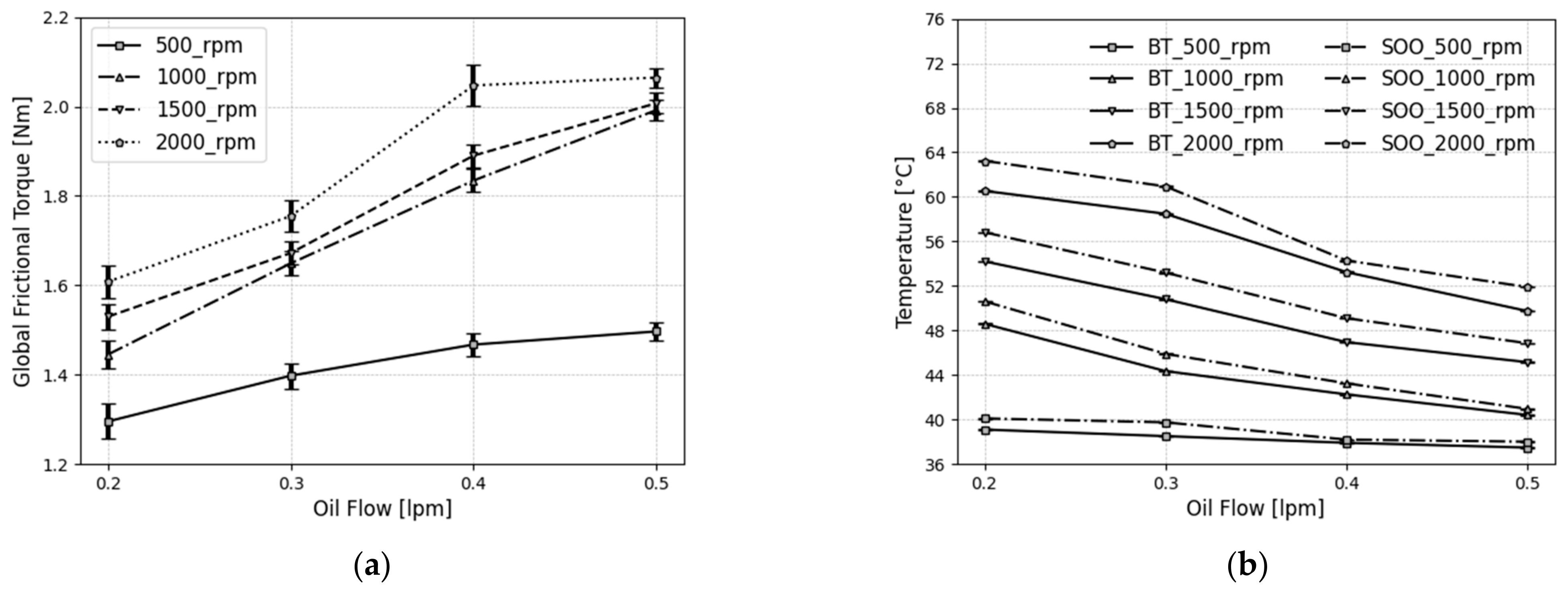
4.1. Determination of Optimum Oil-Flow Rate

The effect of lubrication on TRB power consumption is influenced by viscosity, quantity, and mode of supply, affecting both power consumption [37] and TRB temperature. The first test series aims to determine the optimal oil-flow rate for circulation lubrication. Figure 9 shows steady-state average data of global frictional torque and temperature.
Global frictional torque and power loss increase with the lubricant supply rate to the bearing (Figure 9a). However, TRB temperature (Figure 9b) shows a characteristic curve with a flow rate (1000 to 2500 rpm), where it decreases significantly at the beginning and then slightly as flow rate increases. The slight decrease is due to the effect of the supply oil outlet temperature (Figure 9b; SOO), where at very high flow rates, the temperature difference with the TRB temperature becomes minimal. Reducing the oil-flow rate from 0.5 to 0.2 lpm provides less benefit for 500 rpm compared to other speeds. At 500 rpm, the TRB’s temperature has reached a steady state (37–40 °C) due to the balance between generated friction power and cooling power (Figure 10a).
Increasing the oil-flow rate from 0.2 lpm to 0.3 lpm increases frictional torque by 9.15% and extracts 25.29% of heat from TRB (Figure 9a,b). Further increasing to 0.3 lpm leads to a 17.63% increase in frictional torque, with 14.18% heat removal (Figure 9a,b). Beyond 0.3 lpm, the heat-removal rate does not improve significantly, but the friction torque increases. For oil-flow rates above 0.5 lpm can lead to insufficient pressurization and increased shear heating, causing an increase in friction. The optimum-flow rate for reliable TRB operation is 0.3 lpm, which is chosen for the experiments mentioned in Section 4.2, Section 4.3 and Section 4.5.
At 0.3 lpm oil-flow rate, the oil level in the bearing cup is 25.50 mm (1.35 × bearing width). The SKF model was used to quantify drag friction contribution in the measured global friction under 0.3 lpm. Figure 10b shows computed friction compositions under fully flooded conditions and frictional torque at the raceway contacts dominant, compared to rib and drag friction. Thus, when experimentally analysing the EHL viscous rolling resistance at the roller-raceway contact of TRBs, the drag contributions are small enough and, therefore, not considered.

4.2. Measurements of the Total Torque M t

First, the so-called starting and running torques are measured and analyzed, and the calculated global friction is compared to that predicted by the SKF model. Under slow-speed or starved lubrication, rib-roller contacts have higher frictional forces due to inadequate lubricant film at lower speeds, making them dominant over roller-raceway contacts. The starting torque (Figure 11a,b: Zone 1) of the TRBs is primarily influenced by the sliding and spinning motion of the roller ends at the rib.
However, the running torque (Figure 11a,b: Zone 2) is mainly due to hysteresis and viscous-rolling resistance at the roller-raceway contacts, combined with slide-and-spin-related resistance at the roller-rib contacts. At higher speeds, the slide-and-spin-related resistance decreases as a thicker hydrodynamic lubricant film forms [38], substantially reducing friction loss at the roller-end and rib contact.
Figure 11 shows the measured frictional torque, as well as the calculated torque using the SKF model. The viscosity is calculated at the outer-ring temperature. The trends are similar, but in Zone 1 (starting torque), the predicted value is 15% lower than the experimental value, possibly due to lubrication’s influence on sliding friction constants utilized in the boundary lubrication calculations. In Zone 2 (running torque), the predicted values are within 5% to 8% of the experimental readings, with the sliding-friction coefficient assumed to be 0.002. The product exponent of rotational speed and operating viscosity is lower than the models in Table 1. However, the literature [7,9,16] shows it depends significantly on the used lubricant and its additives. Considering 0.002 in the calculation may lead to a deviation in the order of about 5%.

4.3. Roller-Rib Sliding Torque M s l r i b

Using Equations (15)–(17), the rib torque is calculated for an axial load of 12.85 kN under two different oil-supply temperatures, namely 55 °C and 65 °C. Figure 12a presents the estimated results, with the operating viscosity of the oil at 55 °C and 65 °C being 70.11 and 56.90 mm2/s, respectively. At an oil-supply temperature of 55 °C, the weighting factor of the sliding friction coefficient ( φ b l ; Equation (17)) is small, while the viscosity ratio (actual operating viscosity/rated viscosity) is large. As a result, the sliding rib friction is reduced compared to 65 °C. The calculated rib torque decreases as the rotational speed increases and remains constant after 1400 rpm due to the φ b l value approaching zero. The calculated sliding friction in Figure 12a follows the same trend as experimentally measured by Matsuyama [14] and Zhou [13].

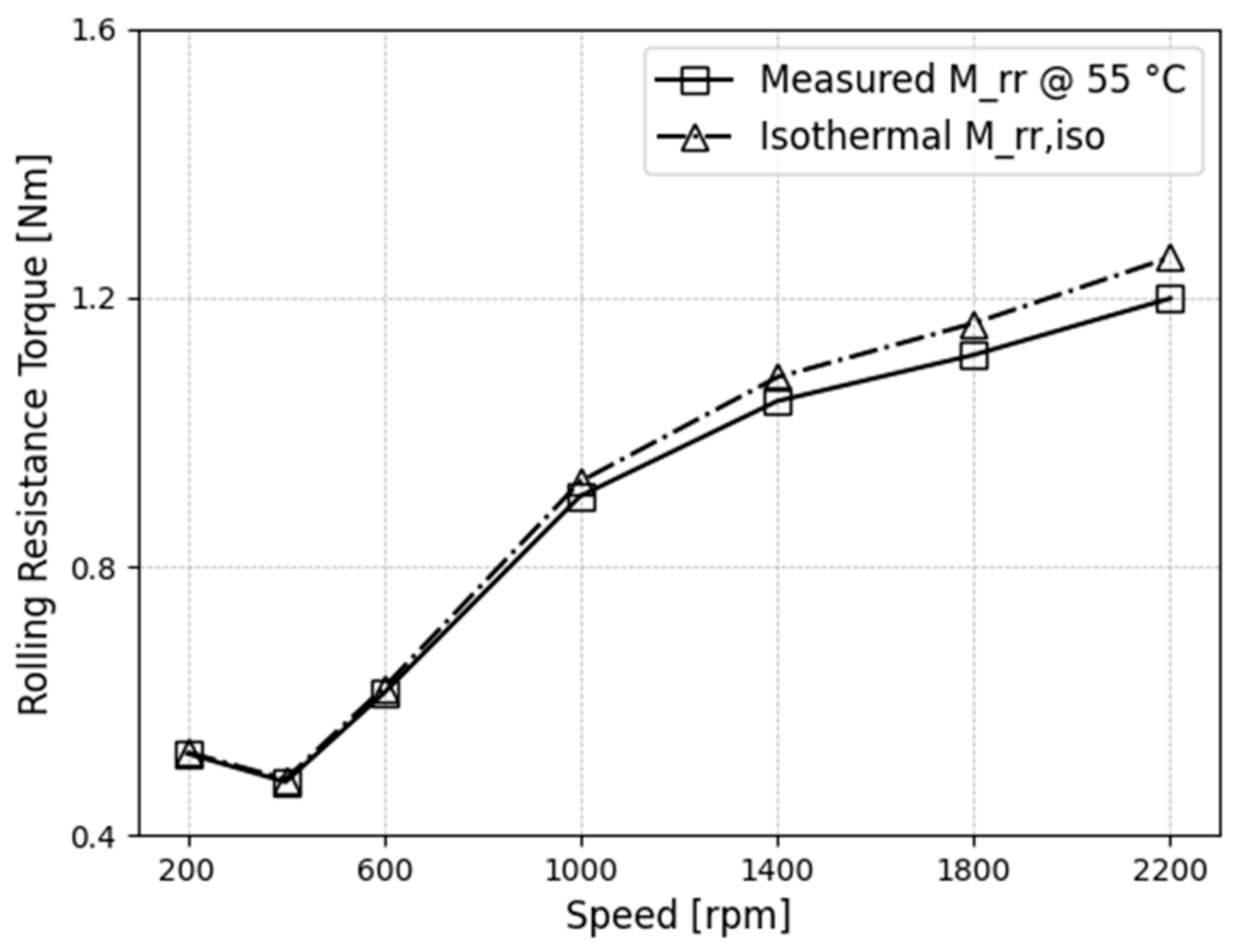
4.4. Rolling Resistance Torque M r r

The raceway’s rolling-resistance torque ( M r r ) is obtained by subtracting the calculated roller-rib sliding torque ( M s l r i b ) from the total torque ( M t ) , while neglecting the drag losses that were verified to be small (Figure 12b). The contribution of rib torque to raceway torque remains almost constant, and the raceway torque is due to a moment that acts in the direction to prevent the roller from rolling.
Figure 13a,b illustrate M r r obtained from the experiments. Moreover, the torques predicted by the models of Aihara [12], Zhou [13], and Matsuyama [14] are compared to the results. It is observed that the Aihara model corresponds with the measured values the least. In contrast, the Matsuyama model, which has been well-validated in a wide range of U, G, and W, agrees with our experimental results (Figure 13a,b). The measured raceway torque remained linear at high U, but the models exhibit non-monotonically behaviour because the models mainly focus on the effect of load (W) on rolling torque and less on speed (U) parameters.
Figure 14 shows the relationship between raceway frictional torque and dimensionless speed parameters (U) under different G and W parameters. Figure 14a–d compares calculated (Table 1) with experimental raceway torques.
Under fully flooded conditions, the relationship between the rolling-resistance torque ( M r r ) and the dimensionless EHD parameters are shown in Figure 14a–d. M r r   exhibits an increase with the dimensionless speed parameter U (Figure 14a–d). As U increases, the center of EHL pressure distribution (Figure 7) shifts significantly towards the inlet region, resulting in an increase of the rolling torque M r r .
The effect of G on M r r is limited. Indeed, G has only a minor influence on the offset of the pressure center in EHL. For small values of W in Figure 14a,b), M r r   increases monotonically with U. For larger values of W (Figure 14c,d)), M r r first decreases with U after which it increases. This behavior is attributed to the thinner oil-film thickness resulting from the formation of mixed lubrication.
Due to the fixed-bearing geometry, the number of rollers and test rig loading constraint, the experimental analysis of W could not cover an extensive range. However, the results in previous studies (Table 1) clearly indicate that the raceway torque indeed depends on the load. Still, this influence is much smaller compared to the influence of the velocity U.
Therefore, the dependence of the applied axial load on the EHL rolling friction is less significant, which is strongly agreed by all the models. Hence, under fully flooded conditions, the effects of G and W are small in the rolling friction, but the effect of U is large.

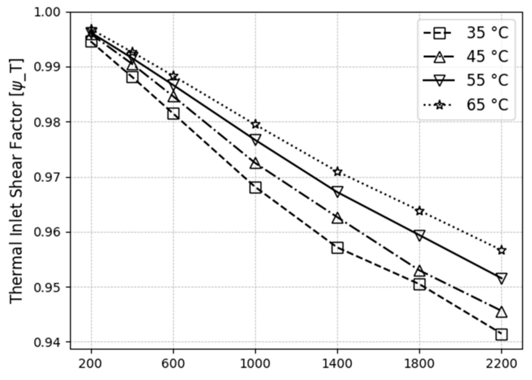
4.5. Thermal Inlet Shear Factor

The thermal EHL factor plays an important role in predicting the raceway torque. Additionally, the film thickness depends on the properties of the lubricant in the inlet region, so this factor is essential for the calculation of the inlet temperature. This effect is a function of the bearing speed and operating viscosity of the oil. Equation (22) is used to calculate the thermal inlet shear factor from the measured rolling-resistance torque for all operating conditions (Figure 15). The thermal shear factor ( φ T ) is close to 1 at low speeds, meaning little shear heating. It decreases to 94% or 96% for higher speeds. This is mainly because SRR = 0. Sliding friction often exceeds rolling friction for low-viscosity lubricants, but the inverse is true for very high-viscosity lubricants [39].
To assess the influence of the thermal inlet factor on the rolling-resistance torque, the measured value of the rolling torque M r r is compared to the isothermal rolling torque value M r r , i s o = M r r / φ T at 9.6 kN and a supply oil temperature of 55 °C (Figure 16). Without the thermal inlet shear factor correction, the rolling-resistance torque would be overestimated by 6 to 8% at speeds above 1400 rpm (Figure 16).
During TRB operation, the rolling-resistance torque ( M r r ) generates frictional forces and dissipates energy, leading to the production of heat. This frictional heat can have various consequences. Firstly, it raises the operating temperature of the TRB, which can cause thermal stress and potentially result in detrimental effects such as reduced lubricant performance and the occurrences of mixed lubrication. Excessive heat can also affect the overall efficiency and performance of the TRB system. To manage the frictional heat in bearings, it is crucial to optimize the design, lubrication, and operating conditions.
To determine the contributions of M r r and M s l r i b components to TRB frictional heat, the experiment is conducted under 12.85 kN and supply oil temperature of 55 °C to measure the global frictional torque. M r r , reconstructed from the measurements using Equation (21) and computed M s l r i b (Equations (15)–(17)) are the leading cause of TRBs to heat up. Ideally, rolling-element bearings operate under pure rolling with slide-to-roll ratios of less than 0.1% [40]. Sliding friction originates from these small amounts of micro-slip in the finite-sized EHL contact and, thus, represents EHL friction. For lower speeds, the main source of heating is due to viscous and compressive heating in the core of the EHL contact. However, at higher speeds and fully flooded conditions, the recirculating lubricant flow in front of the EHL contact induces substantial shear heating in the inlet zone (Figure 17).

5. Conclusions

In this article, experiments were conducted to determine the global frictional torque in a particular Tapered Roller Bearing (TRB). The frictional torque was thoroughly analysed by separating it into rolling and sliding friction contributions using analytical EHL rolling-friction models. The experimental measurements were found to align with the predictions of those theoretical rolling-friction models. Additionally, we investigated the influence of dimensionless parameters U, G, and W on rolling friction and examined the effect of inlet shear heating.
  • In the first part of the study, experiments were performed to determine the optimal oil-flow rate that minimizes drag-loss contributions in the global frictional torque while ensuring adequate lubrication and thermal equilibrium. Following that, a comparison was made between the global friction results and the global SKF friction model.
  • The predicted global frictional loss by the SKF model for velocities below 400 rpm (referred to as the starting zone) were found to be 15% lower than the experimental values. However, for rotational velocities above 400 rpm (referred to as the running zone), the predicted values fell within a range of 5% to 8% of the experimental values. In this study, rolling friction and sliding-rib friction were identified as the primary contributors to the frictional torque of TRBs.
  • The rolling-resistance torque of the TRB was measured for different operating conditions and compared to the theoretical EHL rolling-torque models of Table 1. The model of Matsuyama exhibited a strong predictive capability and demonstrated good agreement with the experimental results.
  • Under fully flooded conditions, the EHL rolling torque M r r exhibits a significant increase with increasing dimensionless speed parameter U. This is due to a significant shift of the pressure centre of the hydrodynamic pressure distribution towards the inlet, resulting in an increase in M r r .
  • The effect of the dimensionless material parameter G on the rolling torque is relatively small. As G increases, the rolling torque decreases for oil temperatures below 45 °C in this work. However, for oil temperatures above 45 °C, G slightly increases the raceway torque at lower U. The effects of G and W on M r r are minor, whereas the effect of U is significant.
  • The thermal inlet shear factor plays a crucial role in rolling friction. For higher rotational velocities, the decrease of rotational torque due to shear heating was estimated to be in the order 6–8%.
  • Analysis of frictional power reveals that the TRB experiences heating at low speeds is primarily due to mixed lubrication friction between the roller and rib contact. At higher velocities, ELH friction becomes dominant and rises quickly with velocity, whereas the rib-raceway friction decreases as it shifts from mixed to full film lubrication.

6. Patents

The proposed test setup is under IP protection and covered in European patent EP22170243.4.

Author Contributions

Test rig conceptualization, M.M. and W.O. Methodology, software and validation, M.M. Resources, W.O. Writing—original draft preparation, M.M., W.O., D.F. and P.D.B. Supervision, D.F. and P.D.B. Project administration, D.F. Funding acquisition, P.D.B. and D.F. All authors have read and agreed to the published version of the manuscript.

Funding

This research was funded by Fonds Wetenschappelijk Onderzoek (FWO), SBO project CONTACTLUB (‘S006519N’).

Data Availability Statement

Not applicable.

Conflicts of Interest

The authors declare no conflict of interest.

Nomenclature

ATFAutomatic Transmission Fluid
bHertzian half width contact (m)
c 1 , c 2 , c 3   a n d   c 4 Constants determined from the experiments.
d w Pitch circle diameter (m)
ERib contact height and roller end (m)
ExBase of natural logarithm = 2.718
h c Central film thickness of the oil (m)
KThermal conductivity of the oil (W/m/°C)
LEffective roller length (m)
m i / o Dimensionless viscous-rolling resistance
m r Moment at the rib contact
NRotational speed (rpm)
PPressure (Pa)
p h Maximum contact pressure (Pa)
r a r m Length of measuring lever arm (m)
r m e a n Mean radius of TRB (m)
u r Mean surface velocity (m/s)
WLoad-per-unit length (Nm)
XCoordinate of rolling direction
x c p X coordinate of center of pressure, m
BExponent of asperity load
BTBearing temperature
C i Weighting factor used to integrate P
COFCoefficient of friction
DDynamic load rating ( 9 π 3 / 2 ) 1 / 2 G U W 3 / 2
D a Mean roller diameter (m)
E Equivalent young’s modulus (Pa)
EHLElasto–Hydrodynamic Lubrication
F a Axial load (N)
F c Mean asperity contacts
F f Frictional force (N)
F N Normal load (N)
F r Load on the roller-end rib (N)
F s i Sliding friction in the raceway roller contact area (N)
F s o Sliding friction in the raceway roller contact area (N)
F s f Sliding friction in the roller end-rib contact area (N)
F t Tangential force (N)
GDimensionless material parameter
G Limiting elastic shear modulus (N/m2)
LThermal-loading factor ( L = η   o β o u r 2 / k )
M L Load-dependent frictional loss (Nm)
M O Load-independent frictional loss (Nm)
M i / o Viscous-rolling resistance (Nm) of inner/outer raceway (Nm)
M t Global frictional torque (Nm)
M r r Rolling-resistance torque (Nm)
M s l _ r i b Sliding friction in the roller end and rib contacts (Nm)
PDimensionless pressure
RBTRoller-bearing tribometer
RiMean inner-raceway radius (m)
R o Mean outer-raceway radius (m)
R 1,2 Equivalent radius of roller-raceway (inner, outer) contacts (m)
ReEquivalent radius in the rolling direction (m)
1 R e = 1 R 1 + 1 R 2 = R 1 + R 2 R 2 R 1
SRRSlide-to-roll ratio
SOISupply-oil inlet
SOOSupply-oil outlet
TEHLThermo–Elasto–Hydrodynamic Lubrication
T i n _ c Temperature of oil at the entry of the Hertzian contact ( ° C ).
T r Rolling tangential force (N)
TRBTapered roller bearing
HDimensionless oil-film thickness (m)
UDimensionless speed parameter
WDimensionless load parameter
XDimensionless coordinate
X c p Dimensionless x coordinate of center of pressure
ZNumber of rollers
UDimensionless speed parameter
η o Operating viscosity of the oil at atmospheric pressure (Pas)
α Pressure viscosity coefficient of lubricant (Pa−1)
β o Temperature-viscosity coefficient of the lubricant ( ° C ).
λ r Fluid film factor for rib contacts
c Surface film constant
S o Critical shear stress of the material (N/m2)
σ o Yield stress of the material (N/m2)
ω r Angular velocity of roller (rad/s)
ω i Angular velocity of the inner ring (rad/s)
φ T ,   r i b Thermal reduction factor of rib contact
φ _ T Thermal reduction factor of raceway
φ r s Kinematic replenishment/starvation reduction factor
µ r i b Frictional coefficient of the rib
μ E H L Sliding friction coefficient in full film
τ Shear stress (N/m2)
τ L Limiting shear stress (N/m2)
γ . Shear rate
μ b l Constant depending on speed; 0.12 for n 0 ; 0.15 for n = 0
φ b l Weight factor for the sliding friction coefficient
G r r   &   G s l Bearing type and geometry
α i Inner raceway angle (rad)
α o Outer raceway angle (rad)
ρ m H m Dimensionless constant

Appendix A

Table A1. Test-Bearing Geometry and Forces.
Murch Wilson T r = ( 1 1 + 0.29 L 0.78 ) R e W α e x p ( 52 79 + 1 94 L 20 63 l n D ( 114 701 + l n ( 1 + 86 209 L 70 99 ))
Thermal inlet shear factor φ T = e x p ( 1.06 · 10 2 L 0.317 l n D ) 1 + 0.411   L 0.707
Patir and Cheng F c F a = e x p ( 1.8 λ 1.2 )
Hamrock Dowson’s h m i m = 3.63 U 0.68 G 0.49 W 0.073 ( 1 e 0.68 k ) R x
Bair and Winder’s γ . = 1 G τ . τ L η l n ( 1 τ τ L )
Reynolds H i 3 d p d x = 3 π 2 U η 4 W 2 [ H i ( ρ m H m ) ρ ]
Dimensionless oil-film thickness H i = H O + X i 2 1 2 π j = 1 n D i j P j
Force equilibrium π 2 = i = 1 n C i P i

Appendix B. Test-Bearing Geometry and Forces

From Figure 4 and Figure 5, the balance of forces and moments on a roller, the following equations are obtained,
D a F s i + F s f D a + l sin γ e M i M o = 0
where F o , F i , and F r act on the outer, inner and rib roller, respectively. M and M o EHL viscous-rolling resistance cause the frictional moment (viscous-rolling resistance). Frictional force M , which acts on the inner ring of a roller, is provided as follows
M = R i F s i + F s f R i + l 2 sin α i + e cos θ + M i = 0
Thus, the sum of torque acting on the inner ring from the rollers, that is, the frictional torque M acting on the bearing can be obtained by the following equation where Z is the number of rollers.
M = M = M Z
From Equations (A1)–(A3),
M = Z 1 D a R i D a ) M i + R i M o + Z 1 D a F s f e R i + D a cos θ + Z 1 D a F s f l D a 2 sin α i R i sin γ
Here,
D a 2 sin α i R i sin γ = D a 2 . R i O P ¯ R i D a 2 . O P ¯ = 0
Hence, Equation (6) becomes,
M = M i + M o = Z 1 D a R o M i + R i M o + Z R o D a e . F s f

Appendix C. Sliding Rib Forces and Moment

M s l _ r i b = Z R o D a e F s f
M s l _ r i b = Z R o D a e µ F r
M s l _ r i b = Z r o D w e µ F a sin 2 γ Z sin α
M s l _ r i b = 2 R o sin γ D a sin α e µ cos γ F a
O P ¯ = D a 2 1 sin γ = 1
M s l _ r i b = e µ cos γ F a ;   Usually ,   γ   very   small   so   cos γ = 1
M s l _ r i b = e µ F a

References

  1. Dowson, D.; Higginson, G.R. Reflections on Early Studies of Elasto-Hydrodynamic Lubrication. Solid Mech. Its Appl. 2006, 134, 3–21. [Google Scholar] [CrossRef]
  2. Dowson, D. Elastohydrodynamic and Micro-Elastohydrodynamic Lubrication. Wear 1995, 190, 125–138. [Google Scholar] [CrossRef]
  3. Gohar, R.; Cameron, A. The Mapping of Elastohydrodynamic Contacts. Wear 1968, 11, 387. [Google Scholar] [CrossRef]
  4. Neurouth, A.; Changenet, C.; Ville, F.; Arnaudon, A. Thermal Modeling of a Grease Lubricated Thrust Ball Bearing. Proc. Inst. Mech. Eng. Part J J. Eng. Tribol. 2014, 228, 1266–1275. [Google Scholar] [CrossRef]
  5. Niel, D.; Changenet, C.; Ville, F.; Octrue, M. A New Test Rig to Study Rolling Element Bearing Thermomechanical Behavior. In Proceedings of the International Gear Conference, Villeurbanne, France, 27–29 August 2018; pp. 121–133. [Google Scholar] [CrossRef]
  6. Pinel, S.I.; Signer, H.R.; Zaretsky, E.V. Design and Operating Characteristics of High-Speed, Small-Bore Ball Bearings. Taylor Fr. Online 2008, 41, 423–434. [Google Scholar] [CrossRef]
  7. Doll, G.L. Causes and Effects of Bearing Damage. In Rolling Bearing Tribology; Elsevier: Amsterdam, The Netherlands, 2023; pp. 205–231. [Google Scholar] [CrossRef]
  8. Doll, G.L. Mitigation of Rolling Bearing Damage Modes. In Rolling Bearing Tribology; Elsevier: Amsterdam, The Netherlands, 2023; pp. 233–252. [Google Scholar] [CrossRef]
  9. Dhanola, A.; Garg, H.C. Tribological Challenges and Advancements in Wind Turbine Bearings: A Review. Eng. Fail. Anal. 2020, 118, 104885. [Google Scholar] [CrossRef]
  10. Hammami, M.; Martins, R.; Fernandes, C.; Seabra, J.; Abbes, M.S.; Haddar, M. Friction Torque in Rolling Bearings Lubricated with Axle Gear Oils. Tribol. Int. 2018, 119, 419–435. [Google Scholar] [CrossRef]
  11. Graf, S.; Werner, M.; Koch, O.; Götz, S.; Sauer, B. Breakdown Voltages in Thrust Bearings: Behavior and Measurement. Tribol. Trans. 2023, 66, 488–496. [Google Scholar] [CrossRef]
  12. Aihara, S. A New Running Torque Formula for Tapered Roller Bearings Under Axial Load. J. Tribol. 1987, 109, 471–477. [Google Scholar] [CrossRef]
  13. Zhou, R.S.; Hoeprich, M.R. Torque of Tapered Roller Bearings. J. Tribol. 1991, 113, 590–597. [Google Scholar] [CrossRef]
  14. Matsuyama, H.; Kamamoto, S. Analysis of Frictional Torque in Raceway Contacts of Tapered Roller Bearings. KOYO Eng. J. Engl. Ed. 2001, 159, 53–60. [Google Scholar]
  15. SKF Group. Rolling Element Bearings Catalogue; SKF: Göteborg, Sweden, 2018; pp. 1–1722. [Google Scholar]
  16. Harris, T.A.; Kotzalas, M.N. Rolling Bearing Analysis Essential Concepts of Bearing Technology; CRC Press: Boca Raton, FL, USA, 2006. [Google Scholar]
  17. Palmgren, A. Ball and Roller Bearing Engineering; SKF Industries Inc.: Philadelphia, PA, USA, 1959. [Google Scholar]
  18. Murch, L.E.; Wilson, W.R.D. A Thermal Elastohydrodynamic Inlet Zone Analysis. J. Lubr. Technol. 1975, 97, 212–216. [Google Scholar] [CrossRef]
  19. Goksem, P.G.; Hargreaves, R.A. The Effect of Viscous Shear Heating on Both Film Thickness and Rolling Traction in an EHL Line Contact—Part I: Fully Flooded Conditions. J. Lubr. Technol. 1978, 100, 346–352. [Google Scholar] [CrossRef]
  20. Goksem, P.G.; Hargreaves, R.A. The Effect of Viscous Shear Heating on Both Film Thickness and Rolling Traction in an EHL Line Contact—Part II: Starved Conditions. J. Lubr. Technol. 1978, 100, 353–358. [Google Scholar] [CrossRef]
  21. Patir, N.; Cheng, H.S. An Average Flow Model for Determining Effects of Three-Dimensional Roughness on Partial Hydrodynamic Lubrication. J. Lubr. Technol. 1978, 100, 12–17. [Google Scholar] [CrossRef]
  22. Bair, S.; Jacobson, B. Chapter 5 Rheological Models for Non-Newtonian Fluids. In Rheology and Elastohydrodynamic Lubrication; Tribology Series; Elsevier: Amsterdam, The Netherlands, 1991; Volume 19, pp. 53–68.
  23. Matsuyama, H.; Kamamoto, S.; Asano, K. The Analysis of Frictional Torque for Tapered Roller Bearings Using EHD Theory. SAE Trans. 1998, 107, 320–329. [Google Scholar]
  24. Matsuyama, H. High Efficiency and Tribology in Rolling Bearings. JTEKT Eng. J. 2012, 1009, 108–113. [Google Scholar]
  25. Houpert, L. Ball Bearing and Tapered Roller Bearing Torque: Analytical, Numerical and Experimental Results. Tribol. Trans. 2002, 45, 345–353. [Google Scholar] [CrossRef]
  26. Gradu, M. Tapered Roller Bearings with Improved Efficiency and High Power Density for Automotive Transmissions. SAE Tech. Pap. 2000, 109, 1696–1705. [Google Scholar] [CrossRef]
  27. Schwarz, M.; Liebrecht, J.; Gonda, A.; Sauer, B. A Study on the Frictional Torque and Temperature Behavior in Tapered Roller Bearings. Forschungsvereinigung Antriebstechnik E.V. 2018, 3, 31–39. [Google Scholar]
  28. Liu, Y.; Fan, X.; Wang, J.; Liu, X. An Investigation for the Friction Torque of a Tapered Roller Bearing Considering the Geometric Homogeneity of Rollers. Lubricants 2022, 10, 154. [Google Scholar] [CrossRef]
  29. Liu, X.; Long, T.; Li, X.; Guo, F. Thermal EHL Analysis of the Inner Ring Rib and Roller End in Tapered Roller Bearings with the Carreau Model. Front. Manuf. Technol. 2023, 2, 29. [Google Scholar] [CrossRef]
  30. Van Wittenberghe, J.; Ost, W.; Rezaei, A.; De Baets, P.; Zsidai, L.; Kalácska, G. Test Setup for Friction Force Measurements of Large-Scale Composite Bearings. Exp. Tech. 2009, 33, 45–50. [Google Scholar] [CrossRef]
  31. Tong, V.-C.; Hong, S.-W. The Effect of Angular Misalignment on the Running Torques of Tapered Roller Bearings. Tribol. Int. 2016, 95, 76–85. [Google Scholar] [CrossRef]
  32. Jiang, Z.; Huang, X.; Zhu, H.; Jiang, R.; Du, S. A New Method for Contact Characteristic Analysis of the Tapered Roller Bearing in Wind Turbine Main Shaft. Eng. Fail. Anal. 2022, 141, 106729. [Google Scholar] [CrossRef]
  33. Liebrecht, J.; Si, X.; Sauer, B.; Schwarze, H. Investigation of Drag and Churning Losses on Tapered Roller Bearings. Stroj. Vestn. J. Mech. Eng. 2015, 61, 399–408. [Google Scholar] [CrossRef] [Green Version]
  34. Marchesse, Y.; Changenet, C.; Ville, F. Drag Power Loss Investigation in Cylindrical Roller Bearings Using CFD Approach. Tribol. Trans. 2019, 62, 403–411. [Google Scholar] [CrossRef]
  35. Wilson, W.R.D.; Sheu, S. Effect of Inlet Shear Heating Due to Sliding on Elastohydrodynamic Film Thickness. J. Lubr. Tech. 1983, 105, 187–188. [Google Scholar] [CrossRef]
  36. NSK Rolling Bearings; General Lubrication Engineering Practice; Springer: Berlin/Heidelberg, Germany, 2015.
  37. Dindar, A.; Hong, I.; Garg, A.; Kahraman, A. A Methodology to Measure Power Losses of Rolling Element Bearings under Combined Radial and Axial Loading Conditions. Tribol. Trans. 2022, 65, 137–152. [Google Scholar] [CrossRef]
  38. Bhushan, B.; Ko, P.L. Introduction to Tribology; John Wiley & Sons: Hoboken, NJ, USA, 2013. [Google Scholar]
  39. Vengudusamy, B.; Enekes, C.; Spallek, R. On the Film Forming and Friction Behaviour of Greases in Rolling/Sliding Contacts. Tribol. Int. 2019, 129, 323–337. [Google Scholar] [CrossRef]
  40. Spikes, H. Basics of EHL for Practical Application. Lubr. Sci. 2015, 27, 45–67. [Google Scholar] [CrossRef] [Green Version]
Figure 1. (a)TRB torque composition; (b) Thermal inlet shear region.
Machines 11 00801 g001
Figure 2. Cross-sectional view of the RBT. (1) Main shaft; (2) Cylindrical roller-support bearing; (3) Angular contact ball-support bearing; (4) Test-bearing adapter; (5) Test-bearing housing; (6) Measuring lever arm.
Machines 11 00801 g002
Figure 3. Test-bearing lubrication modes and thermocouple locations. (a) Forced oil circulation method; (b) oil bath lubrication method.
Machines 11 00801 g003
Figure 4. Forces acting on TRB [12,13,14,23,24,25,31,32].
Machines 11 00801 g004
Figure 5. Simplified model for analysis [12,13,14,23,24,25,31] (a) Raceway contact; (b) Rib contact.
Machines 11 00801 g005
Figure 6. Pressure distribution in EHL contact [14,23].
Machines 11 00801 g006
Figure 7. Coefficient of friction of rib-roller end contacts. (a) Experimentally measured by Zhou [13]; (b) Calculated with SKF Model.
Machines 11 00801 g007
Figure 8. Configuration to measure the global frictional force.
Machines 11 00801 g008
Figure 9. (a) Global frictional torque for different flow rates and TRB speed; (b) TRB outer race and oil out temperature for different flow rates and TRB speed.
Machines 11 00801 g009
Figure 10. (a) Power ratio for friction and cooling power; (b) Frictional torque compositions.
Machines 11 00801 g010
Figure 11. Starting and running torque of TRB and comparison with SKF model ((a,b) = supply oil temperature 55 and 65 degrees under 12.85 kN axial load).
Machines 11 00801 g011
Figure 12. (a) Rib torque from Matsuyama model for an axial bearing load of 12.85 kN; (b) Computed drag loss.
Machines 11 00801 g012
Figure 13. TRB rolling-resistance torque models and measured results (a,b) = supply oil temperature 55 and 65 degrees under 12.85 kN axial load [12,13,14].
Machines 11 00801 g013
Figure 14. TRB rolling-resistance torque with dimensionless speed parameter (ad) = Rolling-resistance torque under 35, 45, 55 and 65 degrees [12,13,14].
Machines 11 00801 g014
Figure 15. Thermal inlet shear factor for different oil supply temperatures.
Machines 11 00801 g015
Figure 16. Influence of the thermal inlet factor on the rolling-resistance torque.
Machines 11 00801 g016
Figure 17. Frictional power of rolling-resistance torque and sliding-rib torque.
Machines 11 00801 g017
Table 2. Roller-bearing test rig and its operating boundaries (RBT).
BearingRoller Bearing
Axial Load2.5–45 kN
Oil flow to test bearing0.07 to 3 lpm
Oil temperature30 °C to 80 °C
Table 3. Oil FVA 3A properties.
FVA 3A Units
Oil typeParaffin-based solvent raffinate
Density884.1kg/m3
Viscosity at 40 °C90.02mm2/s
Viscosity at 100 °C10.41mm2/s
Viscosity index97--
Viscosity-pressure
Coefficient (at 200 MPa)
2.16 × 10³ bar−1 @ 25 °C
1.58 × 10³ bar−1 @ 80 °C
Disclaimer/Publisher’s Note: The statements, opinions and data contained in all publications are solely those of the individual author(s) and contributor(s) and not of MDPI and/or the editor(s). MDPI and/or the editor(s) disclaim responsibility for any injury to people or property resulting from any ideas, methods, instructions or products referred to in the content.

