Article

Tribodynamic Modelling of High-Speed Rolling Element Bearings in Flexible Multi-Body Environments

by
Harry Questa
1,*,
Mahdi Mohammadpour
1,
Stephanos Theodossiades
1,
Colin P. Garner
1,
Stephen R. Bewsher
2 and
Günter Offner
2
1
Wolfson School of Mechanical, Electrical and Manufacturing Engineering, Loughborough University, Loughborough LE11 3TU, UK 2 AVL List GmbH, 8020 Graz, Austria
2
AVL List GmbH, 8020 Graz, Austria
*
Author to whom correspondence should be addressed.
Machines 2023, 11(1), 93; https://doi.org/10.3390/machines11010093
Submission received: 22 November 2022 / Revised: 29 December 2022 / Accepted: 6 January 2023 / Published: 11 January 2023
(This article belongs to the Special Issue Friction and Lubrication of Rolling Element Bearings)

Abstract

:
This study presents a new flexible dynamic model for drive systems comprising lubricated bearings operating under conditions representative of electrified vehicle powertrains. The multi-physics approach importantly accounts for the tribological phenomena at the roller–race conjunction and models their effect on shaft-bearing system dynamics. This is achieved by embedding a non-linear lubricated bearing model within a flexible system level model; this is something which has not, to the authors’ knowledge, been reported on hitherto. The elastohydrodynamic (EHL) film is shown to increase contact deflection, leading to increased contact forces and total bearing stiffness as rotational speeds increase. Results show that for a 68 Nm hub motor operating up to 21,000 rpm, the input bearing EHL film reaches a thickness of 4.15 µm. The lubricant entrainment increases the roller–race contact deflection, causing the contact stiffness to increase non-linearly with speed. The contribution of the lubricant film leads to a 16.6% greater bearing stiffness at 21,000 rpm when compared to conventional dry-bearing modelling methods used in current multi-body dynamic software. This new methodology leads to more accurate dynamic response of high-speed systems necessary for the next generation of electrified vehicles.

1. Introduction

Simulating electrified powertrains using flexible multi-body dynamic (FMBD) models can enable substantial cost and time savings for automotive manufacturers due to a reduced need for physical prototyping. With increasing complexity and operational speeds of these systems, the accuracy at the component level is of major importance. Bearings are crucial structural components and their dynamic response significantly affects the behaviour of the interconnected structures.
Modern electrified motors and transmissions operate at considerably higher speeds and lower loads than conventional powertrains [1]. This leads to much higher lubricant entrainment velocities at the roller–race conjunction of the bearings. Consequently, the elastohydrodynamic (EHL) film thickness can be of the same order of magnitude and often exceed that of the contact deformation predicted by dry Hertzian assumptions; hence, non-lubricated analyses are no longer valid.
The operating conditions of roller bearings in modern electric vehicle (EV) powertrains require dynamic modelling to capture system transients such as time-varying input forces, acceleration and eccentricity. Early quasi-static bearing models [2,3,4,5], are only applicable under steady-state operating conditions; however, the static equilibrium solutions [6,7,8] are of use to calculate load-deflection and individual element loading within dynamic models. Simplified 2-degree of freedom dynamic models [9] consider the purely in-plane motion of the rolling elements in the radial and lateral directions of the bearings for the investigation of the frequency response to defects [10], the varying compliance effect [11] and the radial loading affects [12]. These models increase in complexity up to 5 degrees of freedom (DOF) to observe moment loading and centrifugal effects [13,14]. These analyses assumed a dry contact between the rolling elements and races, which was considered to be valid at lower speeds and high loads. This, however, neglects the effect of the lubricant film thickness in the contact mechanics and thus underestimates the contact deflection and hence the load.
Based on the experimental and numerical findings [15,16,17], the EHL film can be shown to increase the bearing stiffness, which continues to rise non-linearly with speed. It is therefore clear that the lubricant film in roller bearings operating at high speeds must be implicitly included in dynamic analyses.
As stated by Bizarre et al. [18], there are few studies in the open literature that combine the stiffness and damping of an EHL contact with classical bearing dynamics. Early lubricated bearing models use extrapolated formulae to provide a relationship between the load share and film thickness at each element’s contact with the bearing raceways [19]. Aini et al. [20] implemented the extrapolated film approach from the work of Rahnejat and Gohar [19] into a five-DOF bearing equilibrium model. The work computes the deformation at each roller–race contact, combining the EHL film thickness with the elastic deformation of the contacting solids. The force–displacement relationship is shown to follow a non-linear trend. Mohammadpour et al. [21] employed a similar implicit tribodynamic analysis and then utilised a full numerical EHL analysis explicitly for further tribological studies. In their analysis, input shaft speeds of 209 rad·s−1 resulted in much slower entrainment velocities than are applicable for electrified powertrain analyses.
Sopanen and Mikkola [22] modelled the influence of various surface characteristics on bearing dynamics, including contributions from surface waviness, roughness, localised and distributed effects. Their six-DOF model accounts for the Hertzian contact deformation and the EHL film implicitly within the contact. This model was embedded in a multi-body dynamic (MBD) software to utilise its mathematical capabilities. This work does not, however, demonstrate the effect that the EHL film has on bearing stiffness, and the effect on system dynamics using flexible bodies is not analysed [23]. Sawalhi and Randall [24] used a constant preload approach to imitate the stiffening effect of the film. Whilst this effective preload captures the increased contact stiffness due to the presence of the EHL film, the film thickness does not vary based on the contact conditions.
More recently, Liu and Shao [25] investigated the effects of surface waviness, including the effect of the lubricant film using an equivalent stiffness model. Nonato and Cavalca [26] presented a methodology to model EHL contacts using a set of non-linear springs and viscous dampers. Bizarre et al. [18] applied this lubricated non-linear force contact to a five-DOF model of an angular contact ball bearing. This enabled a combined solution scheme for the bearing force equilibrium and the EHL contact. The formulated system of equations was solved, achieving force equilibrium for each rotation of a bearing under constant external load. The authors of this study noted the interest of combining such models within FMBD system level models.
None of the combined models above are embedded within a system level model comprising flexible bodies, and the effect of the change in the contact stiffness due to the lubricant film is not investigated at the system level. Furthermore, the high-speed operation and time-varying loads representative of electrified vehicle transmissions are not considered.
The authors here present, for the first time in the open literature, a coupled simulation approach to combine an implicit lubricated bearing model within a high-speed system level FMBD model. The time-varying system operating conditions reflect that of an electrified powertrain. The kinematic behaviour of a flexible shaft at each time step of a dynamic simulation is passed to the bearing model. A contact slicing method [6] is employed to calculate the reaction forces of the individual rolling elements based on the roller–race contact deflection [27]. The total deflection is influenced by the thickness of the EHL film within the contact, which is implicitly included within the analysis through an iterative procedure. The resulting race forces are returned to the system level model and the equations of motion are solved at each time step. Comparisons are made between modelling the bearings as dry and lubricated. The dynamic results including acceleration, force magnitudes and stiffness variations have been obtained for realistic loading conditions of a 54 kW electric hub motor up to speeds of 21,000 rpm.

2. Methodology

A co-simulation methodology combines a system level model of a flexible shaft and rigid housing, developed in AVL EXCITETM, with component level models of the lubricated bearings, developed in MATLAB and Simulink. Operating conditions such as rotational speed and external forces are defined in the system level model. Time step, iteration accuracy and simulation length are also defined. Material, geometric and rheological properties of the bearings are defined in the component level model. The kinematic conditions from the system level model (i.e., displacements and velocities in all active degrees of freedom) are passed to the component level model at each time step. For each individual rolling element, the non-linear force–deflection relationship is employed in conjunction with the EHL film calculations to compute the contact reaction force between the roller and race. The resultant force on the inner bearing race due to the contact forces and orbital positions of all elements is then returned to the system level model. The equations of motion are then solved, and the time step is advanced once numerical convergence is achieved. A flowchart of these models representing each time step of the simulation is shown in Figure 1.

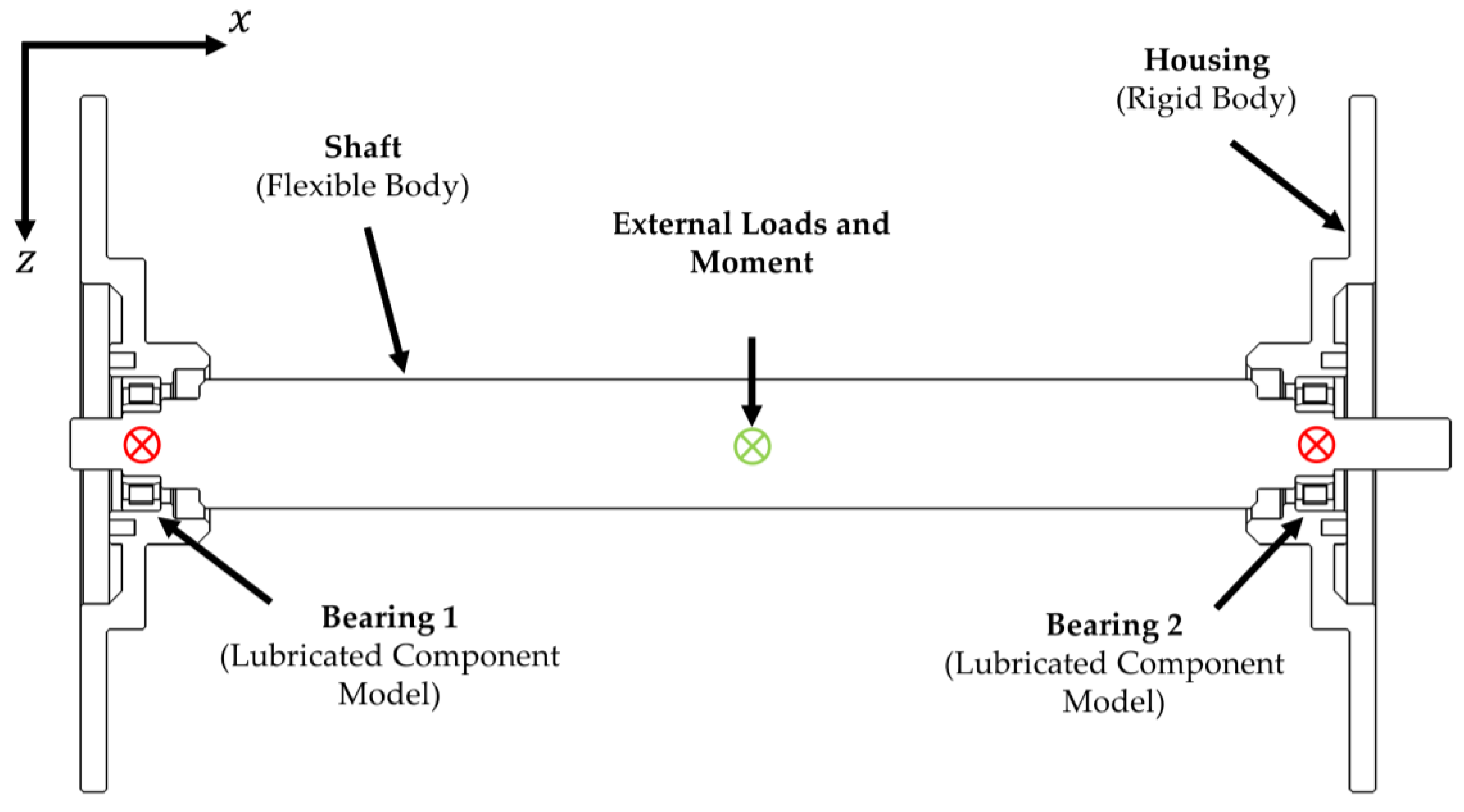
2.1. System Level Flexible Model

The system level model consists of a flexible shaft, supported by two cylindrical roller bearings in a rigid housing (see Figure 2). The shaft is 472.5 mm between bearing centres, with a 50 mm main diameter and 25 mm diameter bearing seats. The cylindrical roller bearings act as interference elements between the shaft and housing. The shaft can exhibit lateral motion in both vertical ( z ) and horizontal ( y ) directions and rotation about the x -axis (see Figure 2). External load is applied at the shaft centre as a time-varying input force, to simulate the gear mesh excitation, or as a static load. The rotational speed is input as a boundary condition.
In typical configurations containing flexible structures, it is possible for both the inner and outer races of a rolling element bearing to move when subject to load. For this analysis, however, it is sufficient to fix the outer race in space and consider only the displacement of the inner bearing race [28]. The housing in this study is treated as a rigid body of infinite stiffness; therefore, the race dynamics of the bearing are influenced only by the motion of the flexible shaft in the model. The loading on the inner race is reacted by the rolling elements on the inner raceway; this must therefore be solved to achieve a dynamic equilibrium.
Within the model, the shaft is treated as a body having linear elastic behaviour and the housing is treated as rigid. The bearings are modelled via non-linear contact forces acting between the shaft and housing.
The shaft is represented by a condensed finite element model and is discretised into a sufficiently high number of partial masses [29]. The total elastic deformation of the shaft is represented by translational and rotational displacement components of these individual partial masses. The mathematical modelling used in the FMBD solver is based on Newton’s equations of motion and Euler’s equation of angular momentum, respectively:
m i 2 x i A b s t 2 = f F , i A b s
t ( I C , i A b s ω i A b s ) = f M , i A b s
where m i and I C , i A b s represent the mass and inertia tensors of the partial masses, i . The vectors of displacement and angular velocity are represented by x i A b s and ω i A b s , respectively, and are related to the centre of gravity of each partial mass. The force and moment vectors, f F , i A b s and f M , i A b s , must be fulfilled for all partial masses in the shaft.
The combination of displacement and rotations of the shaft takes the form:
M q ¨ = f
where M represents the block-diagonal mass matrix of the shaft, consisting of the sub-matrices M i ,   i { 1 , , n } that make up each partial mass of the full shaft. Acceleration, q ¨ , represents the second derivative of the displacement vector of all partial masses, q = ( q 1 , q 2 , , q n ) t . Each element of this vector has six elements associated with it that represent the six degrees of freedom—three rotational and three translational ( q i = ( u t 1 , u t 2 , u t 3 , 1 , 2 , 3 ) t ).
The forces and moments acting on each partial mass are contained in the sub-vectors of force, f = ( f 1 , f 2 , , f n ) t . These are split into a sum of internal force terms, f i i n t , external force terms, f i e x t and non-linear inertia terms, p * . As with the partial mass terms, these are made up of six elements, each representing a degree of freedom:
f i i n t = ( f i , 1 i n t f i , 2 i n t f i , 3 i n t f i , 4 i n t f i , 5 i n t f i , 6 i n t )
where each component of force, f i , k i n t , k = 1 , , 6 is evaluated using the linear-elastic approach.
f i , k i n t = j = 1 6 . n f i , j , k i n t
f i , j , k i n t = ( d i , j , k q ˙ k + k i , j , k q k )
where d and k represent the material damping and stiffness coefficients, respectively.
Grouping the damping and stiffness coefficients into one matrix gives the equation of motion after rearrangement. This equation represents the behaviour of the total system of rigid partial masses that make up the shaft, and considers both general global motion and small body motion (vibrations) [30]:
M q ¨ + D q ˙ + K q = f e x t + p *
The vector of external forces and moments, f e x t , is the sum of excitation forces, f * , and external loads, f a . The external loads and moments applied to the shaft, f a , are determined functions given in time and are input as both time-varying and static loads on the system. The non-linear excitation force term, f * , represents the reaction forces from the lubricated component level bearing model.
f e x t = f * + f a  
Partial mass displacements ( q i ) and velocities ( q ˙ i ) at the bearing locations are output from the dynamic model and used as boundary conditions within the lubricated component level bearing model at each time step of the simulation. This model returns resultant forces and torques on the inner race of each bearing ( f i * ) which are then used to solve the equation of motion (Equation (7)) within the dynamic model (see Figure 1).

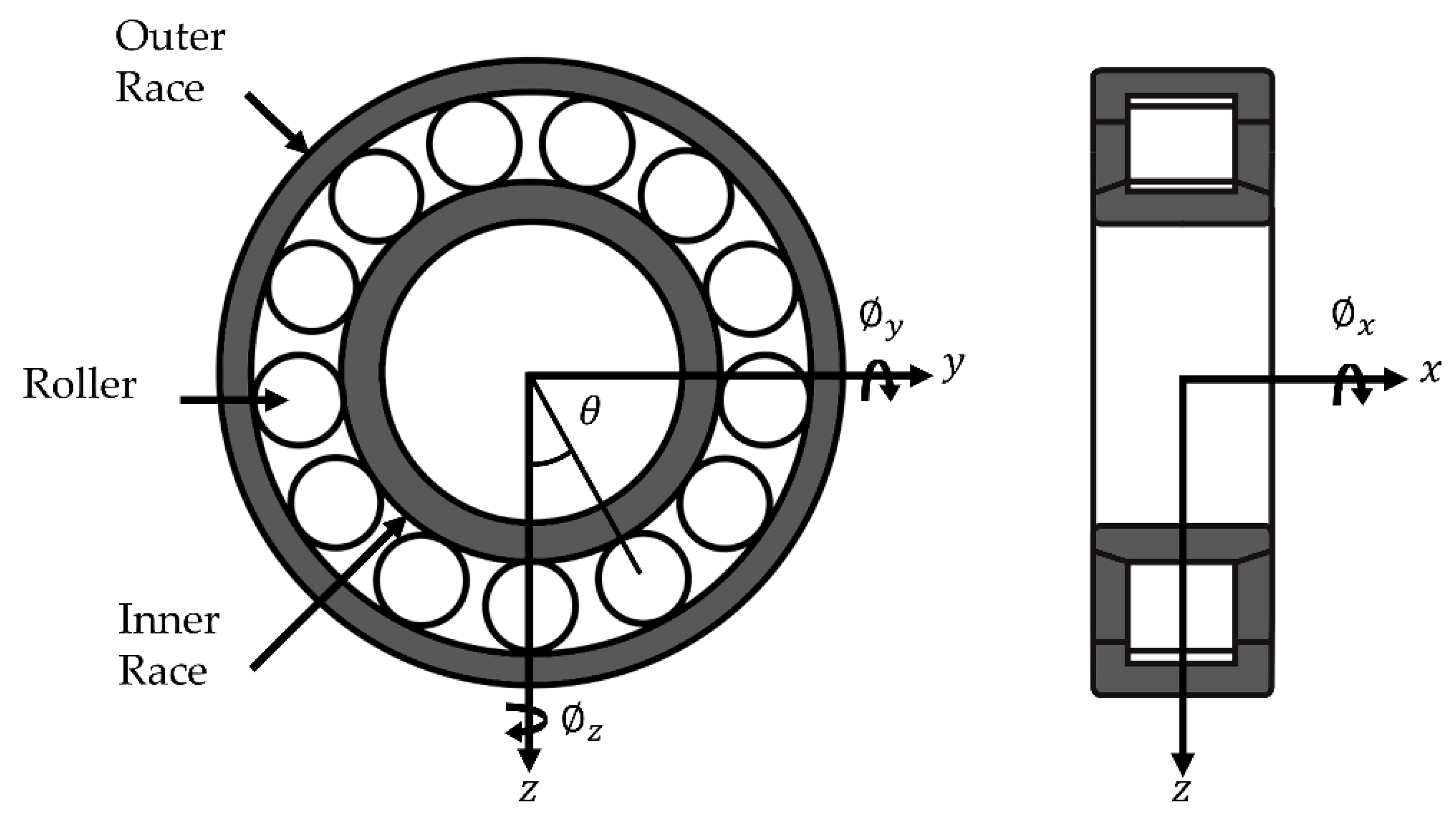
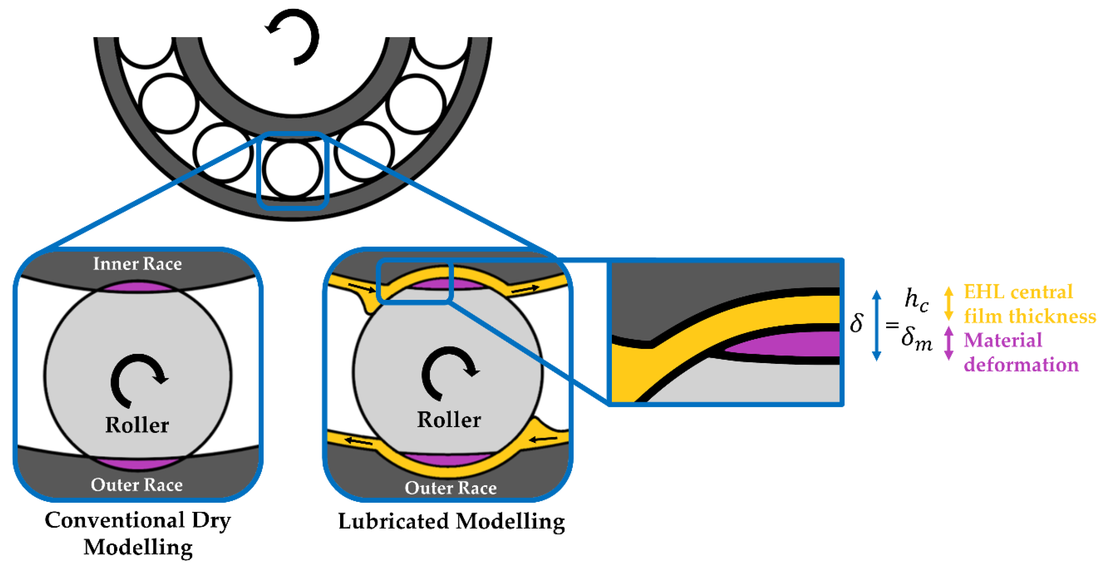
2.2. Lubricated Component Level Model

The displacement and velocity vectors from each node connecting the shaft to the bearings ( q i and q ˙ i respectively) comprise six-DOF. For this lateral DOF model, translations in z and y are considered, as well as angular displacement around the rotational axis, x . A schematic of the bearing is shown in Figure 3.
Between the roller and raceways, under sufficient load, the pressures in the non-conformal contact are high enough to cause elastic deformation of the surfaces and a significant increase in lubricant viscosity. This, combined with relative motion between the contacting bodies, leads to the generation of an EHL contact. The stiffness of the EHL film is typically 1–2 orders greater than the stiffness of the contacting bodies [17]. In this analysis, the film stiffness was calculated using
K E H L = d w d h c
The lowest average film stiffness was 5.1 × 10 9 N/m, which is over one order greater than the contacting material stiffness. The material therefore dominates the stiffness of the contact, and the stiffness of the EHL film can be neglected. The film is modelled as a rigid element that is present between the roller and race [31,32,33].
The contact deformation ( δ ) is therefore a function of the displacement of the inner bearing race, the angular displacement of the roller about the rotational axis ( θ ) thickness of the EHL film ( h c ) and any clearance or radial preload ( ± C ) within the bearing [19,21]:
2 δ = 2 ( h c C ) + z c o s ( θ ) + y s i n ( θ )
Figure 4 demonstrates this more clearly. The total contact deformation is the summation of the central film thickness ( h c ) and the material deformation ( δ m ) predicted from the dry-Hertzian contact assumption. Conventional dry analysis only accounts for the dry material deformation at the contact.
The extrapolated central film thickness for a line contact, assuming a fully flooded contact inlet, is therefore obtained from [34]:
h c = R r [ 3.06 G * 0.56 U * 0.69 W * 0.1 ]
where the following dimensionless parameters are used:
W * = W E r R r l a   ,   U * = η 0 U E r R r   ,   G * = E r α
Comprehensive analytical models [35,36] account for the tilting and skew of the rolling elements. Skew has the effect of varying the entrainment speed along the length of the roller, and tilt will affect the contact gap. Due to the stiff housing and shaft used in this analysis, the tilt and skew angles are very small. The entraining motion and contact gap along the contact length can be considered consistent, and a 1-dimensional analysis for the EHL film thickness is therefore appropriate [14].
The bearings are modelled with a light preload due to mounting interference. In practical applications, the preload is applied to prevent skidding and chaotic behaviour due to the emergence of zero stiffness regions [37]. In contrast, excessive preload can lead to frictional power loss and wear. Assuming pure rolling, the speed of the entraining motion is given by [38,39]:
u = R ω r ( ( R + 2 r ) ( R + r ) )
Due to the dependency of load on the film thickness, an iterative approach is performed to calculate the contact force. Convergence criteria for the EHL film must be met at each time step of the simulation before the bearing forces are returned to the system level model and the equations of motion are solved:
h c m h c m 1 h c m 1 0.001
where m represents the iteration number.
The individual roller–race contact forces are calculated based on the contact deformation. In the case of a rolling element, a cylindrical body of finite length, the contact problem is non-Hertzian. The surfaces cannot be modelled as locally quadratic due to the presence of crowned (rounded) edges [40]. The most widely used technique to calculate the force–deflection relationship is the contact slicing technique. Whilst this does not reflect edge stress concentrations, these stresses are only distributed over a small area and hence can be neglected for the purpose of force equilibrium [41]. In general, this technique is favoured for its simplicity, speed and sufficient accuracy. The contact slicing technique employed in this study was developed by Andreason [6] for modelling these non-Hertzian line contacts.
Modelling the roller–race contacts as a line contact between a cylindrical roller and a flat surface, Lundberg’s [27] expression between contact force per unit length ( w ) and deformation ( δ ) was used.
δ l a = 2 w π E r l a l n π E r l a w
where E r is the equivalent elastic modulus of the two materials and l a is the active length of the roller. This assumes that the pressure distribution is uniform along the length of the contact, and elliptical across it. This neglects side leakage along the contact ( x c ) due to the contact dimensions in this direction being much larger than the dimensions across it ( y c ). This is valid apart from the small regions at the edges of the contact.
From Equation (15), the contact force per unit length of an individual slice along the roller–race contact can be calculated. This is valid if there is no separation of the bodies, i.e., the contact deformation does not become negative ( δ s > 0 ) .
w s = π E r l s ( 0.5 δ s 7.358 l s ) 1.11
where s represents the slice number, and l represents the slice length.
The application of the slicing technique was validated against the open literature. de Mul et al. [28] compared results obtained from an experimental rig with the numerical results calculated using both the approximate slicing technique and the sophisticated non-Hertzian technique [42]. By replicating the geometry of the test bearing used in their analysis, the application of Andreason’s slicing technique used for this analysis was validated with good agreement (see Figure 5). This method is a much faster way of calculating the contact load and moment than more sophisticated methods by de Mul, yet still maintains high accuracy.
The total contact load W and moment T are obtained by summing the contributions from all loaded slices:
W = s w s l s
T = s w s l s x c , s
with x c , s being the distance to the centre of each slice in the conjunction coordinate system. It is assumed that the total contact deflection is shared equally between the inner and outer races despite slight differences in the contact geometry. The entrainment velocity is equal at each contact, which is the governing parameter for the lubricated contact force differences.
Experimental measurements show that the damping of a rolling element bearing arises from multiple sources, including: (1) lubricant film damping at the contacts; (2) material damping due to Hertzian deformations and (3) interface damping between assembled components [17]. These measurements show that damping decreases with rotational speed, tending towards a constant value. Sopanen and Mikkola [22] summarised the findings of Mitsuya et al. [43] and Aini et al. [20], concluding that the film damping is moderate. The linearised viscous damping method adopted in their study is therefore also adopted here. The damping force for each roller is obtained as a factor of the contact stiffness and contact penetration velocity [44]. This is defined as:
| F d | = f d a m p K c q ˙
where K c is the contact stiffness, and the damping factor, f d a m p , is in the range of ( 0.25 2.5 ) × 10 5 as reported by Krämer [44].
At each time step of the analysis, these calculations are performed for each individual roller in the complement. The total bearing force acting on the inner race is solved by splitting the total contact force on each roller into its components and summing their contributions.
f z , i * = N W c o s ( θ ) N F d c o s ( θ )
f y , i * = N W s i n ( θ ) N F d s i n ( θ )  
Due to the bearing preload, contact is maintained throughout the rollers’ orbit; hence no emerging clearances are modelled in the lubricated analysis. The centrifugal forces on the rolling elements are negligible when compared to the contribution of the dynamic load and EHL film in this study. They are also not large enough to cause contact separation from the inner race, and have therefore been neglected.
Surface measurements of the rollers used in this analysis were taken using an Alicona InfiniteFocus Variation Microscope. The composite surface roughness value of a roller and inner race was calculated to be 91.3 nm. This gives a lambda value of 5.88 for the thinnest EHL film at 1000 rpm. The asperity interaction is not considered as the EHL film fully supports the load. Due to the pure rolling and zero sliding assumption, friction at the contacts is therefore neglected and the analysis is performed under isothermal conditions.
The bearing geometry is detailed in Table 1. The rheological and material properties are detailed in Table 2, representing ambient operating conditions in an individual hub-motor transmission.

2.3. Representative Excitation Methodology

The system level model is decomposed, with the excitation forces calculated externally before the application within the model. A separate electrified transmission model is used to generate realistic excitation forces and torques from a spur gear pair and a permanent magnetic synchronous motor (PMSM). This system represents the first stage of an electric hub motor used in automotive applications.
Radial and tangential gear pair forces at the pinion centre, as well as torque fluctuations of the electric motor, are extracted to be used as inputs to the system level model. These are applied as external forces to the shaft, f a , from Equation (8). All bodies in this separate system were modelled as rigid, so that structural excitation forces did not contribute to the resultant forces at the pinion.
The motor has a peak torque of 68 Nm, and a maximum operating speed of 21,000 rpm. The torque transfer through the gear pair reduces as the speed increases due to the torque profile of the PMSM, as shown in Figure 6. The stator tooth forces from the PMSM are neglected in the model due to their minimal contribution to the lateral forces once resolved. For input to the model, the radial and normal forces are simplified by adopting sinusoidal inputs of the same magnitude and frequency of the gear pair at different speeds. The torque ripple from the motor is simplified using the same method.
The gear pair geometry is shown in Table 3 and Table 4.

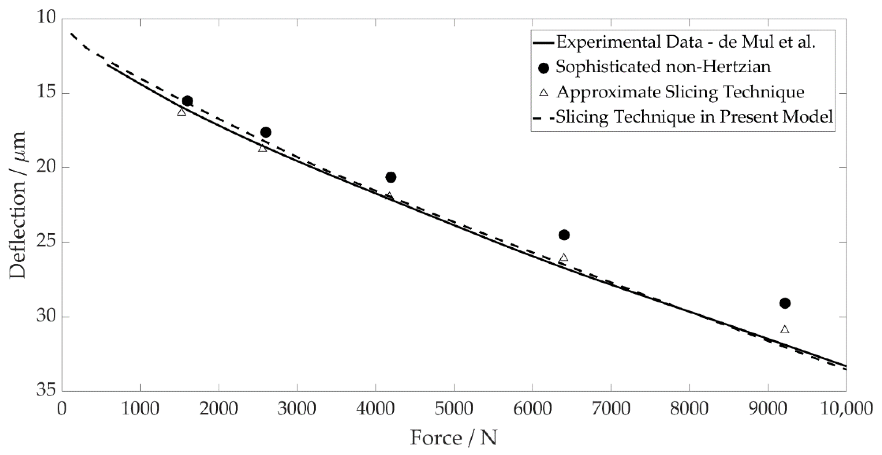
3. Results and Discussion

A quasi-dynamic speed sweep has been performed from 1000 to 21,000 rpm. The simulations are performed every 1000 rpm, refined to 250 rpm intervals throughout a period of system resonance between 12,000 rpm and 14,000 rpm. The operating envelopes are generated by plotting the maximum and minimum values from the steady-state signals at each speed interval. The conjunction level results are obtained from an individual roller and its contact with the inner raceway. The component and system level results are taken from the geometric centre of the inner bearing race, corresponding to the bearing seat on the shaft. The following figures represent results in the y -direction, the largest component of excitation due to the tangential force from the gear meshing.
The contact level results (Figure 7) show a difference in the contact stiffness between the dry and lubricated models. The dry model follows the torque profile of the motor, with stiffness decreasing as the contact forces reduce. The period of resonance leads to the larger amplitude excitation of the shaft, resulting in an increase in the contact stiffness due to the force–deflection non-linearity. The lubricated model, however, shows an increase in the contact stiffness throughout the speed sweep. This is due to the higher levels of deformation at the contact as the lubricant is entrained, which increases with the shaft rotational velocity. This behaviour was experimentally observed by Dietl, concluding that the oil-wedge between the rolling elements and raceways reduces the internal clearance of the bearing and increases its stiffness [17]. The contact stiffness in the lubricated bearing model under the same operating conditions is therefore 24.9% greater at 21,000 rpm.
The peak contact force has been compared between both models. The percentage increase between the dry and lubricated models is shown in Figure 8. This more clearly shows the disparity between both models at the contact, with the largest difference being 9.6 times at maximum speed. During resonance, the inner race force reaches a peak of 1514 N, resulting in surface deformation magnitudes of 0.92 µm and 3.81 µm at the dry and lubricated conjunctions, respectively. As noted in previous works [15], higher loads lead to a greater surface deformation to the film thickness ratio, causing the percentage difference between the dry and lubricated models to reduce. Once the loads reduce as the speed increases, the percentage increase continues to rise.
The total bearing stiffness is a combination of all contact stiffnesses between the elements and raceways. These contact stiffnesses vary non-linearly with force, resulting in the total bearing stiffness varying accordingly. For the dry model, this is clearly demonstrated, with the greater total bearing stiffness at the peak of the resonance due to the greater bearing forces (see Figure 9). This does not, however, capture the change of the total bearing stiffness with speed; the average bearing stiffness does not change. The lubricated bearing is not only stiffer than the dry bearing, but this stiffness also increases with speed. This is shown in Figure 9 by the non-linear increase in the average lubricated bearing stiffness values compared to the constant values for the dry model. The combination of these two factors leads to the lubricated model having a 16.6% greater maximum total bearing stiffness at 21,000 rpm than the dry model.
Due to the greater total stiffness of the bearing, the shaft displacement of the lubricated model is lower both on average and peak to peak for the same applied force in comparison to the dry model (see Figure 10). Through the period of resonance, the large inner race forces result in the roller–race separation of the unloaded rollers within the dry model. This leads to greater shaft displacement as the inner race moves into this region of zero stiffness until roller–race contact is made, and a reaction force is established.
Figure 11 shows that the acceleration peak of the system resonance occurs at 12,500 rpm (3542 Hz) for the lubricated model as opposed to 12,250 rpm (3470 Hz) for the dry model. This shift in natural frequency indicates a stiffer overall system. The magnitude difference between the dry and lubricated models can also be attributed to the unloaded regions of the dry bearing. The contact deformation arising from the loading of the inner race is sufficient to cause the rollers geometrically opposite to become separated from their contacts. Contact is lost between the roller and raceway, leading to zero contact stiffness. The inner race moves into this region until it is reacted by a contact force once again. These regions of zero stiffness are shown in Figure 12, where the minimum stiffness of an individual rolling element and raceway contact in the dry model drops to zero due to separation. For the lubricated model, contact is maintained throughout.
Analysing the conjunction level results from the lubricated model, the contact force due to the gear mesh frequency is shown superimposed on the ball pass frequency as an individual element passes through the loaded region of the bearings (Figure 13 and Figure 14). The higher contact forces result in a reduction in the central film thickness, also shown when observing the variation in film thickness for both plots. At 12,500 rpm, the force and film thickness fluctuations are much larger due to the high excitation levels of the shaft during resonance. At 21,000 rpm, even with a much lower torque transfer through the gear pair, the contact forces are greater than at 12,500 rpm. This is due to the contribution of the film enhancing the total contact deflection and hence increasing the contact force.

4. Conclusions

The new methodology presented has been developed to implement a lubricated bearing model within a flexible system level model. The model implicitly includes the lubricant film at the roller–race contact within the bearing; this is something that has not, to the authors’ knowledge, been reported previously in the open literature. Simulations have been performed up to 21,000 rpm with realistic excitation forces from a first stage reduction gear pair and electric motor. The conjunction level and system level results have been analysed to compare the lubricated and conventional dry-bearing modelling techniques in a flexible multi-body dynamic (FMBD) environment.
Results show that the film thickness reaches 4.15 µm at 21,000 rpm. This leads to 9.6 times greater contact forces and hence 24.9% greater contact stiffness between the dry and lubricated models due to the lubricant entrainment and non-linear Hertzian force–deflection relationship. The contribution of all the rolling elements leads to the lubricated model having a 16.6% greater maximum total bearing stiffness at 21,000 rpm than the dry model. Moreover, this stiffness is shown to increase with speed due to the film thickness increasing with the entrainment velocity; this is something that dry models do not account for.
This increase in the total bearing stiffness leads to a change in the stiffness of the total system. By modelling the shaft as a flexible body, the influence on the natural frequency of the system is seen. The resonant peak at 12,500 rpm shifts 250 rpm higher in the lubricated model, which coincides with the higher frequency excitation from the gear meshing.
Understanding the influence of the roller bearings on the transmission stiffness is of particular importance in automotive applications, and this change shows the effect of the lubricant film on the already complex contact phenomena. Neglecting the effect of the lubricant film can lead to an underestimation of the bearing stiffness, impacting the accuracy of dynamic analyses such as noise, vibration and harshness (NVH) prediction. As transmissions operate at higher speeds with more complex interconnected structures and noise paths, it is important that these behaviours are modelled accurately. Furthermore, underestimation of the contact forces will also lead to a miscalculation of contact pressures, impacting future sub-surface stress and wear analyses for the life predictions of these critical machine elements.
Further developments of this work aim to include more complex rheological phenomena, accounting for thermal and starvation effects at high speeds. Computational efficiency must also be maintained when embedding these models within FMBD environments, due to the iterative nature of the EHL solution.
The presented work establishes the necessity of a multi-physics approach to model the tribology and dynamics of high-speed rolling element bearings. This is essential for future powertrain modelling to ensure accurate component and system level behaviour.

Author Contributions

Conceptualisation, H.Q., M.M. and S.T.; methodology, H.Q. and M.M.; software, S.R.B. and G.O.; validation, H.Q.; formal analysis, H.Q.; investigation, H.Q.; resources, M.M., S.T., C.P.G., S.R.B. and G.O.; data curation, H.Q.; writing—original draft preparation, H.Q.; writing—review and editing, H.Q., M.M., S.T., C.P.G., S.R.B. and G.O.; visualisation, H.Q.; supervision, M.M., S.T., C.P.G., S.R.B. and G.O.; project administration, M.M.; funding acquisition, M.M. All authors have read and agreed to the published version of the manuscript.

Funding

This research received no external funding.

Informed Consent Statement

Not applicable.

Data Availability Statement

All data supporting the results are available in the paper.

Acknowledgments

The authors wish to acknowledge the support of the Loughborough University Wolfson School of Mechanical, Electrical and Manufacturing Engineering PhD Studentship Scheme and the support of AVL List GmbH.

Conflicts of Interest

The authors declare no conflict of interest.

Nomenclature

C Radial clearance (m)
d Body material damping (N·s·m−1)
E Elastic modulus (Pa)
E r Equivalent (reduced) elastic modulus (Pa)
F d Damping force (N)
f d a m p Damping factor (-)
f F Force vector (N)
f M Moment vector (N·m)
f Force on partial mass (N)
f a External loads (N)
f * Non-linear excitation force (N)
G * Dimensionless equivalent geometry (-)
h c Central film thickness (m)
I C Inertia tensor of partial mass (kg·m2)
K Body stiffness matrix (N·m−1)
k Body material stiffness (N·m−1)
K c Contact stiffness (N·m−1)
K b Total Bearing Stiffness (N·m−1)
K E H L EHL Film Stiffness (N·m−1)
l a Active length of roller (m)
l Length of roller slice (m)
m Mass of partial mass (kg)
M Mass matrix of body (kg)
N Partial mass number (-)
n Degree of freedom (-)
p * Non-linear inertia terms (kg·m2)
q Displacement (m)
q ˙ Velocity (m·s−1)
q ¨ Acceleration (m·s−2)
R Bearing inner race radius (m)
r Roller radius (m)
R r Equivalent radius of contact (m)
s Slice number (-)
T Total contact moment (N·m)
u t Translational displacement of partial mass (m)
U * Dimensionless speed parameter (-)
W Total contact load (N)
w Force per unit length (N·m−1)
x Displacement in x-direction (m)
x c Conjunction x-coordinate (-)
y Displacement in y-direction (m)
y c Conjunction y-coordinate (-)
z Displacement in z-direction (m)
Greek Symbols
θ Roller angular displacement (rad)
Rotational displacement of partial mass (rad)
α Pressure viscosity coefficient (m2·N−1)
δ Contact deformation (m)
δ m Material deformation (m)
η 0 Atmospheric lubricant dynamic viscosity (Pa·s)
ρ 0 Lubricant inlet density (kg·m−3)
ω Angular velocity of shaft (rad)

References

  1. Cai, W.; Wu, X.; Zhou, M.; Liang, Y.; Wang, Y. Review and Development of Electric Motor Systems and Electric Powertrains for New Energy Vehicles. Automot. Innov. 2021, 4, 3–22. [Google Scholar] [CrossRef]
  2. Stribeck, R. Ball Bearings for Various Loads. Trans. ASME 1907, 29, 420–463. [Google Scholar]
  3. Palmgren, A. Ball and Roller Bearing Engineering; KF Industries Inc.: Philadelphia, PA, USA, 1959. [Google Scholar]
  4. Jones, A.B. A general theory for elastically constrained ball and radial roller bearings under arbitrary load and speed conditions. J. Basic Eng. 1960, 82, 309–320. [Google Scholar] [CrossRef]
  5. Harris, T.A. Roller Bearing Analysis, 3rd ed.; John Wiley and Sons: New York, NY, USA, 1984. [Google Scholar]
  6. Andréason, S. Load distribution in a taper roller bearing arrangement considering misalignment. Tribology 1973, 6, 84–92. [Google Scholar] [CrossRef]
  7. Liu, J.Y. Analysis of Tapered Roller Bearings Considering High Speed and Combined Loading. J. Lubr. Technol. 1976, 98, 564–572. [Google Scholar] [CrossRef]
  8. De Mul, J.M.; Vree, J.M.; Maas, D.A. Equilibrium and Associated Load Distribution in Ball and Roller Bearings Loaded in Five Degrees of Freedom While Neglecting Friction—Part I: General Theory and Application to Ball Bearings. J. Tribol. 1989, 111, 142–148. [Google Scholar] [CrossRef]
  9. Walters, C.T. The dynamics of ball bearings. J. Lubr. Technol. 1971, 93, 1–10. [Google Scholar] [CrossRef]
  10. Meyer, L.D.; Ahlgren, F.F.; Weichbrodt, B. An Analytic Model for Ball Bearing Vibrations to Predict Vibration Response to Distributed Defects. J. Mech. Des. 1980, 102, 205–210. [Google Scholar] [CrossRef]
  11. Sunnersjö, C. Varying compliance vibrations of rolling bearings. J. Sound Vib. 1978, 58, 363–373. [Google Scholar] [CrossRef]
  12. Matsubara, M.; Rahnejat, H.; Gohar, R. Computational modelling of precision spindles supported by ball bearings. Int. J. Mach. Tools Manuf. 1988, 28, 429–442. [Google Scholar] [CrossRef]
  13. Rahnejat, H.; Rothberg, S. Mulit-Body Dynamics: Monitoring and Simulation Techniques III, 1st ed.; Wiley: New York, NY, USA, 2004. [Google Scholar]
  14. Gupta, P.K. Dynamics of Rolling-Element Bearings—Part I: Cylindrical Roller Bearing Analysis. J. Lubr. Technol. 1979, 101, 293–302. [Google Scholar] [CrossRef]
  15. Questa, H.; Mohammadpour, M.; Theodossiades, S.; Garner, C.; Bewsher, S.; Offner, G. Tribo-dynamic analysis of high-speed roller bearings for electrified vehicle powertrains. Tribol. Int. 2020, 154, 106675. [Google Scholar] [CrossRef]
  16. Stone, B. The State of the Art in the Measurement of the Stiffness and Damping of Rolling Element Bearings. CIRP Ann. 1982, 31, 529–538. [Google Scholar] [CrossRef]
  17. Dietl, P. Damping and Stiffness Characteristics of Rolling Element Bearings-Theory and Experiment; TU Vienna: Vienna, Austria, 1997. [Google Scholar]
  18. Bizarre, L.; Nonato, F.; Cavalca, K. Formulation of five degrees of freedom ball bearing model accounting for the nonlinear stiffness and damping of elastohydrodynamic point contacts. Mech. Mach. Theory 2018, 124, 179–196. [Google Scholar] [CrossRef]
  19. Rahnejat, H.; Gohar, R. The Vibrations of Radial ball bearings. Proc. Inst. Mech. Eng. Part C J. Mech. Eng. Sci. 1985, 199, 181–193. [Google Scholar] [CrossRef] [Green Version]
  20. Aini, R.; Rahnejat, H.; Gohar, R. Vibration modeling of rotating spindles supported by lubricated bearings. J. Tribol. 2000, 124, 158–165. [Google Scholar] [CrossRef]
  21. Mohammadpour, M.; Johns-Rahnejat, P.; Rahnejat, H. Roller bearing dynamics under transient thermal-mixed non-Newtonian elastohydrodynamic regime of lubrication. Proc. Inst. Mech. Eng. Part K J. Multi-Body Dyn. 2015, 229, 407–423. [Google Scholar] [CrossRef] [Green Version]
  22. Sopanen, J.; Mikkola, A. Dynamic model of a deep-groove ball bearing including localized and distributed defects. Part 1: Theory. Proc. Inst. Mech. Eng. Part K J. Multi-Body Dyn. 2003, 217, 201–211. [Google Scholar] [CrossRef]
  23. Sopanen, J.; Mikkola, A. Dynamic model of a deep-groove ball bearing including localized and distributed defects. Part 2: Implementation and results. Proc. Inst. Mech. Eng. Part K J. Multi-Body Dyn. 2003, 217, 213–223. [Google Scholar] [CrossRef]
  24. Sawalhi, N.; Randall, R. Simulating gear and bearing interactions in the presence of faults. Part I. The combined gear bearing dynamic model and the simulation of localised bearing faults. Mech. Syst. Signal Process. 2008, 22, 1924–1951. [Google Scholar] [CrossRef]
  25. Liu, J.; Shao, Y. Vibration modelling of nonuniform surface waviness in a lubricated roller bearing. J. Vib. Control 2016, 23, 1115–1132. [Google Scholar] [CrossRef]
  26. Nonato, F.; Cavalca, K.L. An approach for including the stiffness and damping of elastohydrodynamic point contacts in deep groove ball bearing equilibrium models. J. Sound Vib. 2014, 333, 6960–6978. [Google Scholar] [CrossRef]
  27. Lundberg, G.; Yhland, E. Cylinder Compressed between Two Plane Bodies; SKF: Gothenburg, Sweden, 1949. [Google Scholar]
  28. De Mul, J.M.; Vree, J.M.; Maas, D.A. Equilibrium and Associated Load Distribution in Ball and Roller Bearings Loaded in Five Degrees of Freedom While Neglecting Friction—Part II: Application to Roller Bearings and Experimental Verification. J. Tribol. 1989, 111, 149–155. [Google Scholar] [CrossRef]
  29. Parikyan, T.; Resch, T.; Priebsch, H.H. Structured Model of Crankshaft in the Simulation of Engine Dynamics with AVL/EXCITE. In Volume 3: Engine Systems: Lubrication, Components, Exhaust and Boosting, System Design and Simulation; American Society of Mechanical Engineers: New York, NY, USA, 2001; Volume 67, pp. 105–114. [Google Scholar] [CrossRef]
  30. Offner, G. Modelling of condensed flexible bodies considering non-linear inertia effects resulting from gross motions. Proc. Inst. Mech. Eng. Part K J. Multi-Body Dyn. 2011, 225, 204–219. [Google Scholar] [CrossRef]
  31. Walford, T.L.H.; Stone, B.J. The Sources of Damping in Rolling Element Bearings under Oscillating Conditions. Proc. Inst. Mech. Eng. Part C J. Mech. Eng. Sci. 1983, 197, 225–232. [Google Scholar] [CrossRef]
  32. Dareing, D.W.; Johnson, K.L. Fluid Film Damping of Rolling Contact Vibrations. J. Mech. Eng. Sci. 1975, 17, 214–218. [Google Scholar] [CrossRef]
  33. Mehdigoli, H.; Rahnejat, H.; Gohar, R. Vibration response of wavy surfaced disc in elastohydrodynamic rolling contact. Wear 1990, 139, 1–15. [Google Scholar] [CrossRef]
  34. Dowson, D.; Toyoda, S. A Central Film Thickness Formula for Elastohydrodynamic Line. In Proc. Fifth Leeds-Lyon Symp. Tribol. Mech. Eng. Publ.; Elsevier: Amsterdam, The Netherlands, 1979; pp. 60–65. [Google Scholar]
  35. Nelias, D.; Bercea, I.; Paleu, V. Prediction of roller skewing in tapered roller bearings. Tribol. Trans. 2008, 51, 128–139. [Google Scholar] [CrossRef]
  36. Majdoub, F.; Saunier, L.; Sidoroff-Coicaud, C.; Mevel, B. Experimental and numerical roller skew in tapered roller bearings. Tribol. Int. 2020, 145, 106142. [Google Scholar] [CrossRef]
  37. Mevel, B.; Guyader, J. Routes to chaos in ball bearings. J. Sound Vib. 1993, 162, 471–487. [Google Scholar] [CrossRef]
  38. Spikes, H. Basics of EHL for practical application. Lubr. Sci. 2014, 27, 45–67. [Google Scholar] [CrossRef] [Green Version]
  39. Shi, X.; Wang, L. TEHL analysis of high-speed and heavy-load roller bearing with quasi-dynamic characteristics. Chin. J. Aeronaut. 2015, 28, 1296–1304. [Google Scholar] [CrossRef] [Green Version]
  40. Singh, K.P.; Paul, B. Numerical Solution of Non-Hertzian Elastic Contact Problems. J. Appl. Mech. 1974, 41, 484–490. [Google Scholar] [CrossRef]
  41. Harris, T.A.; Kotzales, M.N. Advanced Concepts of Bearing Technology, 5th ed.; Taylor and Francis Group: Boca Raton, FL, USA, 2007. [Google Scholar]
  42. De Mul, J.M.; Kalker, J.J.; Fredriksson, B. The contact between arbitrarily curved bodies of finite dimensions. J. Tribol. 1986, 108, 140–148. [Google Scholar] [CrossRef]
  43. Mitsuya, Y.; Sawai, H.; Shimizu, M.; Aono, Y. Damping in Vibration Transfer through Deep-Groove Ball Bearings. Trans. Jpn. Soc. Mech. Eng. Ser. C 1992, 58, 3714–3721. [Google Scholar] [CrossRef]
  44. Krämer, E. Dynamics of Rotors and Foundations; Springer: Berlin/Heidelberg, Germany, 1993. [Google Scholar]
Figure 1. Flowchart of Models.
Machines 11 00093 g001
Figure 2. System Level Model Schematic.
Machines 11 00093 g002
Figure 3. Bearing Schematic.
Machines 11 00093 g003
Figure 4. Dry vs. Lubricated Roller–Race Contact.
Machines 11 00093 g004
Figure 5. Contact Level Validation.
Machines 11 00093 g005
Figure 6. PMSM Torque Profile and Maximum and Minimum Torque Fluctuation.
Machines 11 00093 g006
Figure 7. Rolling Element Contact Stiffness—Dry vs. Lubricated Maximum Values.
Machines 11 00093 g007
Figure 8. Rolling Element Contact Force—Dry vs. Lubricated Percentage Increase.
Machines 11 00093 g008
Figure 9. Inner Race Stiffness—Dry vs. Lubricated Operating Envelope.
Machines 11 00093 g009
Figure 10. Inner Race Displacement—Dry vs. Lubricated Operating Envelope.
Machines 11 00093 g010
Figure 11. Inner Race Acceleration—Dry vs. Lubricated Operating Envelope.
Machines 11 00093 g011
Figure 12. Rolling Element Contact Stiffness—Dry vs. Lubricated Minimum Values.
Machines 11 00093 g012
Figure 13. Film Thickness vs. Contact Force 21,000 rpm.
Machines 11 00093 g013
Figure 14. Film Thickness vs. Contact Force 12,500 rpm.
Machines 11 00093 g014
Table 1. Bearing Specification.
ParameterValue
Inner race bore diameter25 mm
Pitch diameter60 mm
Roller diameter8.8 mm
Roller length15 mm
Number of rollers17
Radial interference2 µm
Table 2. Lubricant and Material Properties.
ParameterValue
Pressure viscosity coefficient ( α )2.1 × 10⁻⁸ Pa−1
Atmospheric lubricant dynamic viscosity ( η 0 )0.08 Pa·s
Lubricant inlet density ( ρ 0 )833.8 kg·m−3
Modulus of elasticity of contacting solids ( E ) 210 GPa
Poisson’s ratio of contacting solids ( ν ) 0.3
Table 3. Pinion Geometry.
ParameterValue
Number of teeth17
Normal module0.004 m
Normal pressure angle20°
Helix angle at pitch circle
Active tip diameter0.076 m
Active root diameter0.065 m
Width0.035 m
Table 4. Gear Geometry.
ParameterValue
Number of teeth51
Normal module0.004 m
Normal pressure angle20°
Helix angle at pitch circle
Active tip diameter0.212 m
Active root diameter0.202 m
Width0.030 m
Disclaimer/Publisher’s Note: The statements, opinions and data contained in all publications are solely those of the individual author(s) and contributor(s) and not of MDPI and/or the editor(s). MDPI and/or the editor(s) disclaim responsibility for any injury to people or property resulting from any ideas, methods, instructions or products referred to in the content.

