Article

Enhanced Integrator with Drift Elimination for Accurate Flux Estimation in Sensorless Controlled Interior PMSM for High-Performance Full Speed Range Hybrid Electric Vehicles Applications

School of Electrical and Information Engineering, Tianjin University, No. 92 Weijin Road, Tianjin 300072, China
*
Author to whom correspondence should be addressed.
Machines 2023, 11(7), 769; https://doi.org/10.3390/machines11070769
Submission received: 5 June 2023 / Revised: 21 July 2023 / Accepted: 21 July 2023 / Published: 24 July 2023
(This article belongs to the Special Issue Advanced Data Analytics in Intelligent Industry: Theory and Practice)

Abstract

:
Interior Permanent Magnet Synchronous Motor (IPMSM) motion-sensorless speed control necessitates precise knowledge of rotor flux, speed, and position. Due to numerous non-ideal aspects, such as converter nonlinearities, detection errors, integral initial value, and parameter mismatches, the conventional first-order integrator’s estimated rotor flux experiences a DC offset (Doff). Low-pass filters (LPF) with a constant cut-off frequency yield accurate estimates only in the medium- and high-speed range; however, at the low-speed area, both magnitude and phase estimates are inaccurate. The presented technique resolves the aforementioned issue for a broad speed range. In order to achieve precise flux estimation, this article presents an improved technique of flux estimator with two distinct drift mitigation strategies for the motion-sensorless field-oriented control (FOC) system of IPMSM. Using the orthogonality of the α - and β -axes, the proposed drift elimination system can estimate drift in different situations while maintaining a high level of dynamic performance. The stator flux linkage (SFL) computation in the synchronous coordinate is established from the estimation of the rotating shaft’s permanent magnetic flux linkage orientation and the statistical equations model of the SFL. By comparing the calculated SFL vector to the SFL vector derived from the stator winding voltage and currents integral model with a drift PI compensation loop, a feedback loop is formed to neutralize integral drift, and the rotational speed and position of an IPMSM is estimated utilizing the vector product of the two flux linkages in a phase-locked loop. Theoretical interpretation is presented, and Matlab Simulink simulations, as well as experimental outcomes, consistently demonstrate that the suggested estimation techniques can eliminate the phenomenon of flux drift.

1. Introduction

IPMSMs (Interior Permanent Magnet Synchronous Motors) are applicable to a broad range of industrial applications and are extensively employed [1]. Measuring the motor’s speed is necessary to acquire high precision and dynamic performance control for an AC motor with a broad speed range. Conventionally, PMSM is equipped with position sensors in order to achieve digital commutation and closed-loop control. However, the configuration of a position sensor is not always practicable due to space limitations, extreme environments, or other exceptional circumstances. In addition, implementing position sensors will increase manufacturing costs and complexity. Sensorless control does not directly measure speed and has emerged as the standard solution for controlling PMSM and IPMSM drives.
Sensorless control’s essential aspect is position estimation, which replaces conventional position sensors. Position-sensorless control mechanisms are classified into two main categories based on their control structures: non-feedback motion-sensorless control strategies and feedback loop motion-sensorless control strategies. The voltage/frequency (V/f) control methodology, as a typical non-feedback motion-sensorless control strategy, is extensively used in engineering domains due to its affordable expenses for installation, practicality, and insensibility to the application atmosphere [2,3]. Nonetheless, if the ratio between voltage and frequency is not appropriately chosen, the V/f control approach fails to maintain synchronization readily and can even cause damage to electronic devices under conditions of initial substantial load or instantaneous load changes. In order to enhance the stability of the traditional V/f control technique [3], stabilization loops need to be implemented. Contrary to the V/f control method, I/f control generates the desired voltage using a current closed-loop regulator that ensures stable start-up, self-stabilization of torque and power angle, preventing overshoot, and anti-disturbance capability [4,5].
In motion-sensorless feedback-loop control approaches, rotor position knowledge is crucial. Feedback-loop motion-sensorless control mechanisms are additionally categorized into two subcategories based on the distinct assessment principles for rotor-position information: injection of a high-frequency carrier signal method (IHFCSM) [6,7,8] as well as model-based techniques [9,10,11,12,13,14,15,16,17]. The IHFCSM offers a promising solution by utilizing magnetic saliency identification and introducing a signal with an HF to interact with rotor-orientation-dependent saliencies. Such approaches can perform well at zero to low speeds and are irrespective of the back electromotive force (EMF) and machine parameters. Still, as the machine speed increases, they encounter issues such as additional losses, ripples in the torque, high-frequency noise, and power losses, which can only be applied to saliency motors and constrained control performance brought on by the additional filter [8]. Model-based solutions, comprising flux linkage estimation methods [13,14,15,16,17] and back-EMF estimation strategies [9,10,11,12], are passive techniques that do not rely on signal injection. In the preceding, numerous EMF observers have been established and utilized in industrial and commercial environments. These techniques have demonstrated satisfactory performance in regions of moderate and high speed. However, as the motor RPM goes down, the rotor orientation may be imprecisely acquired since the EMF gradually decreases, and disappearance is insufficient to provide accurate knowledge about the rotor orientation at minimal or zero velocities. To accomplish sensorless position control of the PMSM throughout the entire speed domain, hybrid position estimation solutions [9,10,11] that combine the aforementioned two approaches are commonly employed. The SFL estimation technique is anticipated to facilitate broader speed domain sensorless operations compared to the EMF estimation strategy because of the proven fact that the rotor flux linkage remains unchanged and is practically constant regardless of speed; however, since sensors always have a Doff, a pure integrator has drift issues.
A precise flux linkage acquisition mechanism with an online compensation strategy for drift and residual drive system errors is described by Kyung-Rae Cho and Jul-Ki [13]. Advocating a simple integration approach using a simple resonant-type observer design produced exceptional flux linkage estimation fulfilment down to 1.3 Hz stator frequency. In reference to stator flux linkage estimation, an integration scheme based on a fifth-order filter is discussed by [14], along with a high-pass filter (HPF) and a logical calculation element; this scheme achieves identical phase and amplitude-frequency characteristics as a simple integrator at any synchronous rotational frequency. A novel approach for estimating flux linkage, utilizing the dual (SOGI-FLL), is introduced by [15]. This method can mitigate the effects of Doff and high-order harmful harmonics while enhancing the system’s dynamic response. A linear regression-based nonlinear observer has been designed for motion-sensorless control of IPMSMs, and a pseudo-high-pass filter is employed to remove the impacts of Doff [16]. The problems of DC saturation and Doff are solved by the Gopinath model SFL observer, which integrates the currents and voltage models [17]. In the majority of such flux linkage-based estimator approaches, the LPF is typically used in combination with angle adaptation techniques or a feedback-loop flux linkage observing system. This is performed to eliminate issues related to DC saturation and Doff while simultaneously increasing the speed of iterative operation. However, system stability must be carefully considered alongside these measures.
In the scientific literature, two well-established techniques have been proposed for flux estimation in PMSMs. The preliminary approach is based on the PMSM voltage-flux principle. Back EMF is calculated using known voltage and current information in a stationary reference frame (SRF). Subsequently, fluxes are determined by integrating the electromagnetic field [18]. However, this approach has a number of disadvantages; the main issue is associated with using the open-loop integrator, which includes the saturation difficulties induced by the Doff in currents or, commonly in EMF, the Doff caused by an unknown initial state in EMF. Other problems are the same phenomenon of saturation and Doff problems for high-order harmonics and slow-speed analysis challenges [19]. Since actual voltages and currents in the SRF are determined using a method commonly referred to as Clark transformation, the key benefit of the method is that fluxes can be estimated without knowing the rotor position. One common approach to improving the efficacy of flux estimation using a voltage model is to use a low-pass filter (LPF) instead of a pure integrator.
The LPF can address the saturation difficulties, and the Doff is drastically reduced because it is inversely proportional to the LPF frequency [20,21]. However, the LPF induces a phase transition and a reduction in flux magnitude, and this approach malfunctions whenever the motor rpm is equal to or slightly lower than the filter’s cut-off frequency. To resolve this issue, a compensation term is added to account for the phase delay and amplitude decreases. The LPF can adequately enhance the accuracy of a flux estimation technique that employs a voltage equation with a compensator [22,23,24]. Nonetheless, the presence of an EMF signal introduces disturbances into the system and degrades its significance. Furthermore, harmonics also cause challenges, such as saturation state and Doff for other harmonics, which cannot be resolved using the LPF and compensator developed for the fundamental harmonic. Considering the potential benefits of no model limitations along with a low noise level, a flux estimator emerges as an appealing approach for motion-sensorless control.
In contrast, the drift induced by a simple integrator has limited use in precise motor control. Similar to the EMF, the stator flux linkage (SFL) contains information about the rotor’s position. However, unlike back EMF, the magnitude of the SFL amplitude waveform remains constant regardless of the speed. Another technique for improving the flux estimator’s performance is employing the closed-loop method by adjusting the based on approximate frequency [25]. An important example of this is the second-order generalized integrator-frequency-locked loop (SOGI-FLL) proposed in [26], demonstrating an exhibiting excellent efficiency under constant-speed conditions. Meanwhile, these techniques are inapplicable in situations involving variable speeds, including trajectory tracking, because filters generally compromise static and dynamic performance.
Recently, the fundamental frequency of an EMF has been extracted using a Second-Order Generalized Integrator (SOGI) before integration [27,28,29]. However, the SOGI technique has limitations in suppressing the DC component. To address this issue, a third-order generalized integrator has been proposed [30]. Despite these improvements, the voltage model is unable to correctly handle transient machine performances, such as accelerating, decelerating, crossing zero speed, and low speeds, due to a negative correlation between flux amplitude and rotation rate. The second approach depends on the stator current flux model of a PMSM, which approximates fluxes directly by utilizing inductances, rotor permanent magnet flux, and monitored currents [31,32]. This method overcomes most of the flux estimation shortcomings associated with the voltage model technique by eliminating the need for an open-loop integrator. The current model is particularly efficient at low speeds and during speed reversal procedures, such as stand-still speed crossings.
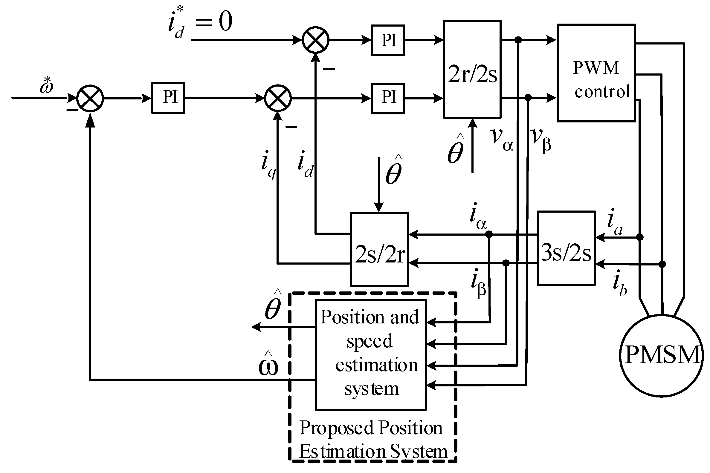
In this article, the authors propose two compensation techniques to determine and eliminate the drift error generated by the voltage transducer during rotor position estimation. The aim is to achieve precise rotor position estimation without any phase error. The compensator employs a PI controller to remove the undesired signal and ensure that the flux magnitude matches the actual value. Typically, adaptive observers estimate the flux using the time-variable, full-order PMSM model. At least one of the model’s equations must contain a speed-dependent element, while the observer should be constantly speed-adaptive. Obtaining rotor speed is typically the final phase of the assessment procedure. Consequently, cumulative errors, time delays, and system noises always have an impact on the speed estimation. This erroneous speed assessment is feedback to the adaptive flux estimator, causing the precision of both the flux and speed estimator to deteriorate gradually. Undesirable outcomes, such as limit cycles, increased delays, or noise sensitivity, can degrade the system’s overall performance, especially at very low stator frequencies with low fundamental excitation. Fortunately, the proposed method includes two Doff compensators and non-adaptive observers that utilize a PI controller to eliminate the error signal. It ensures that the flux magnitude matches the actual value. Furthermore, since they do not rely on rotor speed adaptation, both Doff compensation algorithms are essentially sensorless and thus not affected by speed estimation errors. Moreover, an integral part of a particular PI correction system at the voltage model level makes both observers robust against measurement drift and Doff. From a structural perspective, each estimator is summarized. The rotational speed and position of an IPMSM can be estimated in a phase-locked loop (PLL) utilizing the SFL’s cross-product derived from the integral model of stator voltage and currents, as well as the estimated SFL. To validate the proposed method, the two compensation algorithms were employed to eliminate the drift error component. These algorithms underwent theoretical investigation, and the validity of the method was verified through simulations and laboratory experiments using Matlab Simulink as well as 7.5 kW IPMSM.

2. Traditional IPMSM Flux Estimator

The most straightforward flux estimator is based on the voltage model with a simple integrator [32]. The rotor’s speed and orientation can be computed using the accurate model of an IPMSM via the integration of α - β -axis flux linkage, which is commonly achieved using EMF.

2.1. PLL/ArcTan Based Voltage Model Flux Estimator for Motion-Sensorless Control

Figure 1 depicts the space vector representation of an IPMSM. The α β frame represents the SRF, while the d q frame represents the synchronous coordinate system. The d ^ q ^ frame is utilized in vector control without sensors with a rotor reference frame. Moreover, θ r and θ ^ r represent the real and estimated position of the rotor, respectively.
The computational model that describes the relationship between voltage and sinusoidal flux distribution of IPMSM in a α β frame can be expressed as follows:
v α v β = R + L α L α β L α β R + L β i α i β + ω r ψ f sin θ cos θ
where v α and v β are the α - and β - axes stator coil voltage, i α and i β are α - and β - axes armature current, R indicates a stator coil resistance, θ is rotor electrical angular position, ψ f indicates flux linkage, = d d t is the differential’s function, and ω r denotes rotor speed. L α , L β , and L α β are transitory variables with the following values:
L α L β L α β = 0.5 L d + L q + L d L q cos 2 θ L d + L q L d L q 1 sin 2 θ L d L q 2 sin θ cos θ
Substituting (2) into (1) yields the following:
v α v β = R + L q R + L q i α i β + ψ f α ψ f β
where ψ f α and ψ f β are the α - axis and β - axis equivalent rotor flux linkage. In [12], stator voltage and current integration are used to obtain stator flux linkage ψ s α and ψ s β as well as rotor flux linkage ψ f α and ψ f β . The system then utilizes a conventional PLL or ArcTan function to estimate the rotor position (RP) θ ^ and speed ω ^ , as depicted in Figure 2.
ψ s α = e s α d t = v α R i α d t ψ s β = e s β d t = v β R i β d t ψ f α = v α R s i α d t L q i α ψ f β = v β R s i β d t L q i β
The voltage-type rotor flux estimation model of (3) can determine the rotor flux solely based on the stator voltage and currents of the motor. While flux estimation is related to stator resistance, which is easy to detect and relatively stable, it is important to note that this estimation model has a simple structure and provides accurate results. In Figure 2, the structure of the voltage model is demonstrated. In this situation, the SFL is also applicable to the motor position, satisfying the following equations:
ψ s α = ψ f cos θ ψ s β = ψ f sin θ
From (4) and Figure 2, it is evident that the voltage model contains a pure integration loop. The pole of the integral is located at the origin point in the s-plane. As a result, the simple integration is highly sensitive to DC drift and variations in stator resistance in the EMF signals, particularly when the motor operates at slow speeds. In theory, the gain of the integrator is infinite when the input signal frequency is zero, indicating that even a minimal Doff input can lead to a large DC output, generating a significant Doff component in the output signal until saturation. In addition, pure integrators also have an initial value problem. Incorrect initial value selection can lead to a constant DC bias in the integration operational results.
The input signals x ( t ) = A m sin ω 1 t + θ 0 + D ( D represents Doff) are used for integration operation [20], and the output of the pure integration link can be obtained through Laplace transform and inverse transform, as follows:
y ( s ) = ξ 1 X s 1 s y ( t ) = A m ω 1 sin ω 1 t + θ 0 π 2 + A m ω 1 cos θ 0 + D t
From (6), it can be seen that if there is a Doff, the third term in the equation indicates that this offset will eventually lead to integrator saturation as the integration time increases. From the second item in the equation, it can be seen that there is also a Doff A m ω 1 cos θ 0 in the output signal, which is related to the initial phase (i.e., the initial time of integration).

2.2. Low-Pass Filter

The voltage model uses a pure integration link, where the pole of the pure integration link is located at the origin, and the system is in marginal stability. Any small Doff input will ultimately lead to integration saturation and incorrect magnetic flux estimation. In the voltage model, this issue is typically resolved by passing the output of the pure integrator through a high-pass filter s s + ω c , where ω c is the corner frequency.
Based on comprehensive consideration, Equation (7) is obtained by:
y = x s · s s + ω c = x s + ω c
According to (7), after adding a high-pass filter, the original simple integrator is transformed into an LPF [20,33]. The model is asymptotically stable, and the LPF has a pole in the left half of the plane.
The input signals x ( t ) = A m sin ω 1 t + θ 0 + D transform the output signal through a first-order LPF in order to obtain the following:
Y ( s ) = 1 s + ω c A m ω 1 s 2 + ω 2 1 cos θ 0 + s s 2 + ω 2 1 sin θ 0 + D s Y ( s ) = A m ω 2 1 + ω 2 c ω 1 1 s + ω c + ω c s 2 + ω 2 1 s s 2 + ω 2 1 cos θ 0 + ω c s s 2 + ω 2 1 + ω 2 1 s 2 + ω 2 1 1 s + ω c sin θ 0 + D ω c ω c s s + ω c
where ω c is the corner frequency of the first-order LPF. Taking the Laplace inverse transformation of (8) yields:
y ( t ) = A m ω 2 1 + ω 2 c sin ω 1 t + θ 0 θ + A m ω 2 1 + ω 2 c sin θ θ 0 e ω c t + D ω c 1 e ω c t
In Equation (9), θ = arctan ω 1 ω c , the last term of (9) is generated by the Doff of the input signal, which is different from the pure integration stage; this quantity gradually approaches a stable value D ω c exponentially. Moreover, the larger ω c is, the smaller the final stable value. This is the inhibitory effect of the first-order LPF on integral saturation. The second term of (9) is caused by different initial moments of calculation, and this quantity will decay exponentially to zero with the passage of calculation time t . The more extensive the ω c is, the faster the decay. Therefore, the first-order LPF eliminates the problem of non-zero initial values for pure integrators. However, at the same time, amplitude error and phase error are inevitably introduced.

3. The Proposed Techniques of the Flux Estimator for IPMSM Sensorless Control

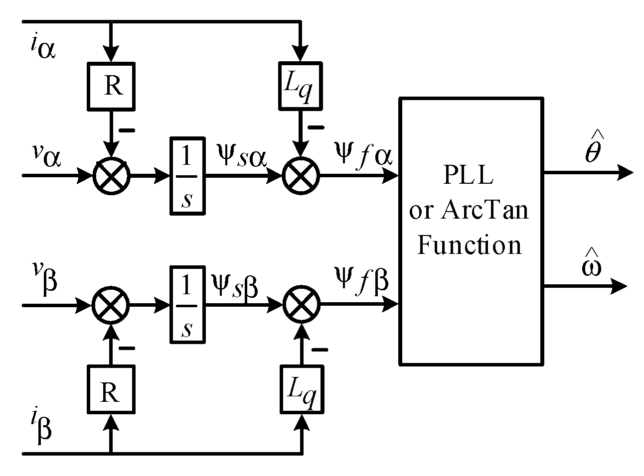
The presence of a Doff component in the stator voltage significantly impacts the evaluation of flux linkage. In order to compensate for integration errors, it is essential to incorporate feedback along with the integrator structure. The stator flux linkage, like the back EMF, contains knowledge about the rotor position (RP). However, unlike back EMF, the magnitude of the flux linkage’s amplitude waveform remains constant regardless of speed. This property makes the flux linkage a more reliable state to estimate, particularly at low speeds. This characteristic becomes very crucial at slow speeds and during rapid transients when the speed estimation is often imprecise. In addition, the proposed flux observer technique improves overall robustness. The proposed flux estimator consists of a pure integrator, a drift eliminator, and a flux linkage observer with a PLL/arctangent function. The voltage-based model in stator reference (10) is a highly desirable approach for sensorless stator–flux estimation in all sinusoidal flux distribution AC machines. However, a pure integrator is sensitive to drift because sensors always include a Doff. It integrates the calculated EMF as follows:
d d t ψ ^ s = e ^ e s t = u ^ s i s R ^ s , ψ ^ s 0 = ψ ^ s 0
Transforming the stator currents i a and i b into a α β -coordinate system, then, i α and i β can be written as:
i α i β = 1 / 3 1 / 3 3 3 3 3 i a i b
The stator current in the d q frame can be expressed as follows:
i d i q = cos θ sin θ sin θ cos θ i α i β
The accumulative flux-linkage vectors can be defined as a function of the two-phase rotating frame (the d-q frame), which is written as Equation (13), also known as the current model:
ψ ^ s = ψ ^ sd ψ ^ sq = L ^ d L ^ q · i ^ d i ^ q + ψ f 0
where ψ ^ sd , ψ ^ sq is the estimated flux; L ^ d and L ^ q are the estimated inductances on the d- and q-axis, respectively; and ψ f is a permanent magnet flux linkage.
The transformation from the d - q to the α - β frame is stated below:
ψ ^ s α ψ ^ s β = cos θ ^ e s t sin θ ^ e s t sin θ ^ e s t cos θ ^ e s t · ψ ^ sd ψ ^ sq = T ψ ^ sd ψ ^ sq w h e r e   T = cos θ ^ e s t sin θ ^ e s t sin θ ^ e s t cos θ ^ e s t
The following results can be established by substituting Equation (13) with Equation (14) and transferring the currents from the d - q frame to the α - β frame:
ψ ^ s α ψ ^ s β = T L ^ d 0 0 L ^ q · T 1 i ^ d i ^ q + T ψ f 0 w h e r e   T 1 = cos θ ^ e s t sin θ ^ e s t sin θ ^ e s t cos θ ^ e s t ; i ^ d i ^ q = T ( θ ^ e s t ) 1 i ^ α i ^ β a n d   T = cos θ ^ e s t sin θ ^ e s t sin θ ^ e s t cos θ ^ e s t
Since the stator coil currents are used directly to estimate the flux, and no integral operation and stator resistance are required, Equation (15) is more precise than the voltage model (4) in the slow-speed domain. Specifically, the current sensor provides information about the stator current, thus enabling excellent estimation performance, particularly at low speeds. Due to this advantage, the suggested approach is efficient and capable of accurately estimating position in the slow-speed domain. For the PLL design in Figure 3, when the angle of intersection concerning ψ s and ψ ^ s is minimal, it results in ψ ^ s × ψ s / ψ ^ s ψ s = sin ( θ θ ^ ) θ θ ^ , and the feedback-loop transfer function of PLL near the equilibrium point is given as follows:
G ( s ) = k p s + k i s 2 + k p s + k i
This is a typical second-order system with a pole and zero. The proportion and integration coefficients designed in this paper are given as follows:
k p = 2 ξ ω n k i = ω n 2
In Equation (17), ξ represents the system-damping coefficient, whose assigned value ξ = 0.7 , whereas the variable ω n denotes the undamped oscillations frequency of the system, which is based on the motor’s RPM operating range. For this calculation, we assume ω n to be 1000 rad/s. Since PLL’s open-loop transfer function has a couple of integration links, for the step input of speed, θ is a ramp input, which can achieve no static error; i.e., θ θ ^ 0 in a steadystate, θ is a parabolic input with static error for the speed ramp input, and the magnitude of the static error is in reciprocal proportion to k i .

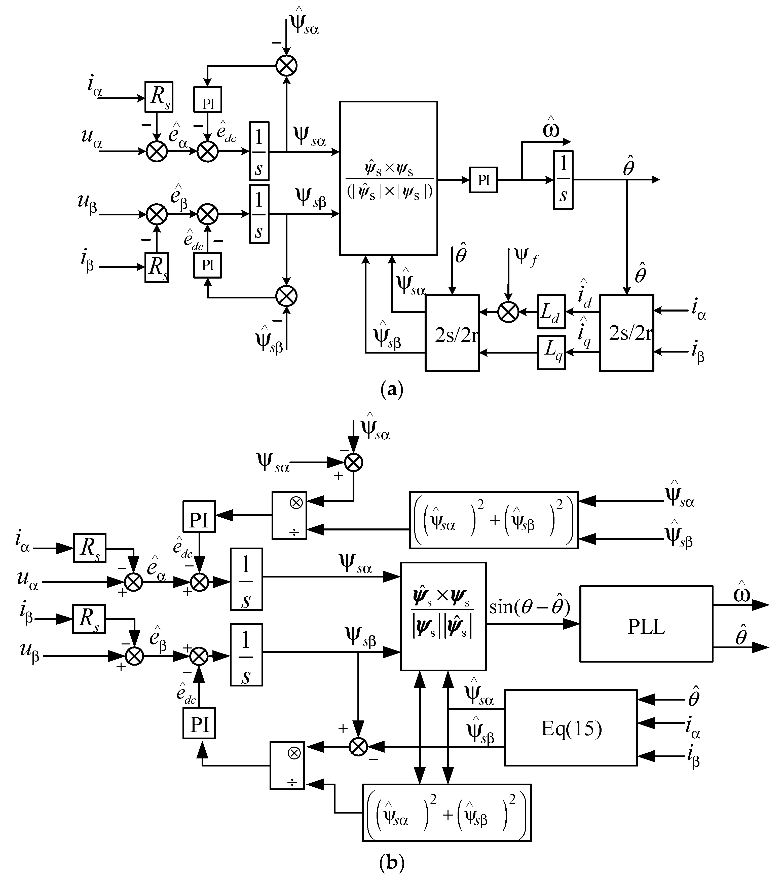
3.1. Drift Elimination Strategy 1

Figure 3a depicts a drift elimination technique established on the orthogonality of the α - and β -axes that is assured by the physical structure of the motor and a three-phase balance.
A physically perceptive method is devised below. In the most common scenario of accurate amplitude flux control, the optimal stator–flux trajectory ψ s i , with respect to the stator reference, is a symmetrical circle centered on the origin. If a flux Doff of ψ o f f s e t appears, the rotation of a resultant stator flux ψ s is also a circular shape; however, its origin is shifted by ψ o f f s e t . Consequently, the estimated flux offset ψ ^ o f f s e t can be determined using Equation (18), which provides knowledge about circular eccentricity.
ψ ^ o f f s e t = ψ ^ s ψ ^ s i ψ ^ s = ψ ^ s e i θ ^ s ; ψ s i ψ s ψ s e i θ ^ s
The back EMF and stator flux are defined as:
e α β + e o f f s e t = u ^ s + u s o f f s e t i s R ^ s ψ α β + ψ o f f s e t = e α β + e o f f s e t
where e o f f s e t and ψ o f f s e t represent the Doff signal, which is fundamentally a time-proportional signal. Based on Figure 4, the Doff error signal can be calculated by:
ψ o f f s e t e o f f s e t = 1 s 1 + k p s + k i s 1 s a s ψ o f f s e t e o f f s e t = s s 2 + k p s + k i a s lim s ψ o f f s e t = lim s s s 2 + k p s + k i lim s ψ o f f s e t = 0
The flux DC drift ψ o f f s e t is caused by an input voltage Doff u ^ s or by an inaccuracy in the initial state of the stator flux ψ s 0 . A PI feedback correction employing e ^ d c (18) is used to eliminate ψ ^ o f f s e t . The design determines e ^ d c , which compensates for the disturbances u ^ s , especially forcing ψ ^ s onto a circular path centered on the origin. The disturbance compensation employs a PI compensator with the parameters k p and k i to estimate the DC-drift input vector e ^ d c = k p + k i s ψ ^ o f f s e t , which is depicted in Figure 4. In the drift elimination strategy 1, during a feedback loop, the PI controllers k p and k i coefficients are modified to 103 and 205, respectively. In addition, the PI controller eliminates steady-state inaccuracy. The feedback loop PI parameters compensator affects the sensorless control performance. Increasing the k p and k i values increase the overshoot and settling time while decreasing the steady-state error. Therefore, the control system needs more time to eliminate the Doff in real time; selecting k p and k i lower leads to degraded controller performance.
Moreover, the inaccurate selection of feedback PI controller parameters ( k p and k i ) results in overall system performance instability. Therefore, these parameters need to be accurately selected. Thus, drift elimination strategy 2 is proposed, which is more accurate, simple, and robust.

3.2. Drift Elimination Strategy 2

This algorithm utilizes ψ ^ d 0 = ψ s + d α β ψ ^ s ψ ^ α 2 + ψ ^ β 2 with the Doff component eliminated by the Doff compensation. The drift elimination strategy 2 response to removing the Doff error component from the system is faster than that of drift elimination strategy 1, as shown in Figure 5. Therefore, this approach is more efficient compared to drift elimination drift elimination strategy 1.
The transfer function equivalent of a feedback-loop simple integrator with PI compensation is obtained by:
H s = ψ ^ s e ^ = s s 2 + k p · s + k i · z , z = ψ s ψ ^ s ψ ^ s
The weighted variable z , which is defined by the magnitude of the stator–flux error, accentuates a frequency-adaptive performance of the estimator; a minimal z results in wide bandwidths. If z 0 , the analogous structure is a high-bandwidth simple integrator with no phase delay.
Therefore, the estimation error due to drift is given by:
e α = ψ α + d α ψ ^ α ψ ^ α 2 + ψ ^ β 2 = ψ f cos θ + d α ψ ^ f cos θ ^ ψ ^ f cos θ ^ 2 + ψ ^ f sin θ ^ 2 e β = ψ β + d β ψ ^ β ψ ^ α 2 + ψ ^ β 2 = ψ f sin θ + d β ψ f sin θ ^ ψ ^ f · cos θ ^ 2 + ψ ^ f · sin θ ^ 2
e α = d α d ^ α e β = d β d ^ β
where d ^ α and d ^ β represent the PI controller’s estimated drift signal. Taking the derivation of (23), one can derive:
e α = d α d ^ α = d α k p μ α k i μ α d t
where μ α = ψ f cos θ + d α ψ ^ f cos θ ψ ^ α 2 + ψ ^ β 2 assuming that:
μ α e α
By substituting (25) into (24) and computing the derivation, the second-order differential function can be determined as:
e α k p e α k i e α
which is the standard dynamic equation of the PI controller; e α will exponentially converge to zero. Similarly, it has been deduced that if e α 0 , it is assumed that e β will converge exponentially to zero because drift is proportionate to the time e α and e β , to which both are equivalent to 0 . To obtain a rapid asymptotic estimate, free of oscillations for u ^ o f , the following PI controller parameters can be determined: k i = ω 0 2 , ω 0 = ω min d , d 3 , 9 , and k p = 2 ξ ω 0 ξ 0.5 , 1 , where ω min represents the minimal stator frequency.
The integral component of PI retains the input Doff computation u ^ α o f . If the EMF e ^ (10) is assessed precisely by u ^ s , then ψ s = ψ ^ s = ψ s and z = 0 ; subsequently, z 0 and a simple integrator has been obtained. In drift elimination Drift Elimination Strategy 2, the derivative estimation provides rapid estimation and improved computation in the presence of the same Doff.
The flux estimator functions as an integrator with no delay and high dynamics. The designed flux estimation method is capable of being utilized for the sensorless control of AC motors with sinusoidal flux distribution, such as PMSM, IM, etc., over a broad speed range. Consequently, drift elimination scheme 2 ensures faster Doff rejection.

4. Comparative Simulations

4.1. Simulation Setup

This section presents a series of MATLAB/Simulink-based simulations, which evaluate the efficacy of the proposed drift elimination techniques in mitigating integration drift. Simulink is used to create a model of the proposed flux estimator. The Field-Oriented Control (FOC) scheme serves as the fundamental control scheme. Figure 6 illustrates the schematic structure of the sensorless IPMSMs control structure designed for the nonlinear flux estimator. It incorporates speed PI regulators and a pair of current PI controllers. The RP and speed are determined using a nonlinear flux observer, except during the start-up phase, where an open-loop motion-sensorless starter technique is employed. The algorithms proposed for estimating stator flux and rotor speed are simple yet highly effective across a range of operating speeds. Table 1 presents the key parameters of IPMSM.

4.2. Simulation Results

This section presents the comparison of two proposed techniques for drift elimination in motion-sensorless control techniques. The performance of the Doff ripples and serious distortions of stator flux and speed suppressed by the proposed drive and control scheme are verified by Matlab Simulink. The investigation is conducted on a salient pole PMSM operating at 300 rpm while subjected to α-axis and α β -axis voltage disturbance at the no-load condition. To demonstrate the efficiency of the drift elimination strategy 2(DM2), Figure 7 displays comparison results using integrated drift correction methods (DM1). Both strategies work effectively for both uniform and variable speed trajectories.
Additionally, the proposed drift elimination schemes can successfully eliminate drift from the flux and do not induce any steady-state error. The drift elimination response under the drift elimination scheme 1 (DM1) control is slower compared to the drift elimination scheme 2 (DM2) control. The drift elimination under DM2 is smoother and more stable, resulting in a faster response. Figure 7 demonstrates that DM2 exhibits higher accuracy in estimating the drift amplitude and removing drift more rapidly (i.e., it has a smaller setting time) than DM1. DM2 significantly enhances the dynamic performance and estimation accuracy of sensorless control.
In summary, this paper demonstrates that DM2 exhibits better dynamic characteristics. To quantitatively evaluate both methods, the steady state position estimation error (SSPEE) is defined as the deviation between the position generated by the flux estimator after drift elimination and the actual position of IPMSM. A similar definition applies to speed error in estimation (SSSEE). The time required for drift compensation, represented by TSSPEE, is highlighted in Table 2, and the results validate the preliminary simulation.
The observed speed and position estimation error, a Doff error component, varying between 0 V and 0.6 V, is artificially injected into the stator voltage α -axis at the no-load condition. The observed speed, estimated RP and speed errors, artificially injected Doff and DC-drift estimation error, estimated fluxes, and the errors of estimated fluxes based on the DM1 and the DM2 with PLL are shown in Figure 7a–d, respectively. Although both estimators perform well, the DM2-based estimators perform better than the DM1-based one.
Figure 8 depicts the dynamic characteristics of the proposed algorithm when the DC offset error component (Dec) is adjusted. When a 1 V DC drift error is intentionally introduced to the stator voltage v α at 2 s, significant fluctuations are observed and maintained in the estimated speed as well as RP angle. The proposed drift elimination schemes initiated the real-time DC offset error component. At 4 s, even with the addition of Dec, when set to 1.5 V, the compensation successfully eliminates the flux, speed, and position estimation pulsation, which results in a stable value. Despite the variation in the magnitude of the Dec, it can be demonstrated that the real-time compensating characteristic is exhibited effectively. The drift elimination response under DM1 control is slower, whereas the drift elimination under DM2 is smoother, more stable, and faster in response. To quantitatively evaluate both methods, Table 3 validates the preliminary simulation.
Figure 9 depicts the dynamic features of the two proposed algorithms with a constant speed of 300 r/min under α β -axis voltage disturbance. First, when a 1 V DC drift error is artificially applied to stator voltage v α β at 2 s, a severe pulsation is maintained in the estimated flux, speed, and RP angle. Both proposed drift elimination schemes effectively address the real-time DC offset error component. Figure 9 demonstrates that the estimated fluxes closely match the actual ones. The PLL-based drift elimination strategy 2 successfully overcomes the speed, flux, and rotor position angle transient at 0.5 s, with the estimated flux waveforms accurately tracking the actual fluxes of the motor. Secondly, at 4 s, the Dec is increased by 1.5 V. The compensation eliminates the speed and position estimation pulsations despite the additional disturbance, ensuring a stable value. Even though the magnitude of the Dec varies under α β -axis, it can be demonstrated that the real-time compensating characteristic is exhibited well. The response for drift elimination under DM1 control is slower.
On the other hand, drift elimination under DM2 is smoother and more stable, with a faster response. It indicates that DM2 is more accurate for estimating the drift amplitude and removing drift than DM1. Table 4 validates the preliminary simulation.

5. IPMSM Motor Experimental System Based on dSPACE

The structural diagram of the real-time simulation experimental system for IPMSM based on dSPACE is shown in Figure 10. The system consists of a computer, dSPACE single-board DS1103, transfer circuit, inverter, current and voltage detection link, and IPMSM. The voltage and current signals of the IPMSM are detected by Hall sensors and sent to the transfer circuit for conditioning. The IPMSM experimental platform, depicted in Figure 11, is constructed in the laboratory. It mainly consists of IPMSM, DC Cabinet, an inverter, and control methods using the dSPACE equipment in the loop system. Matlab software is used for simulation modeling with a real-time interface that compiles and uploads seamlessly to dSPACE 1103. The position of the rotor is detected by a transducer. However, this position is only used for comparison with the estimated position and is not utilized for IPMSM speed control. An LPF is used to filter speed assessment obtained from the differential of the observed rotor position.
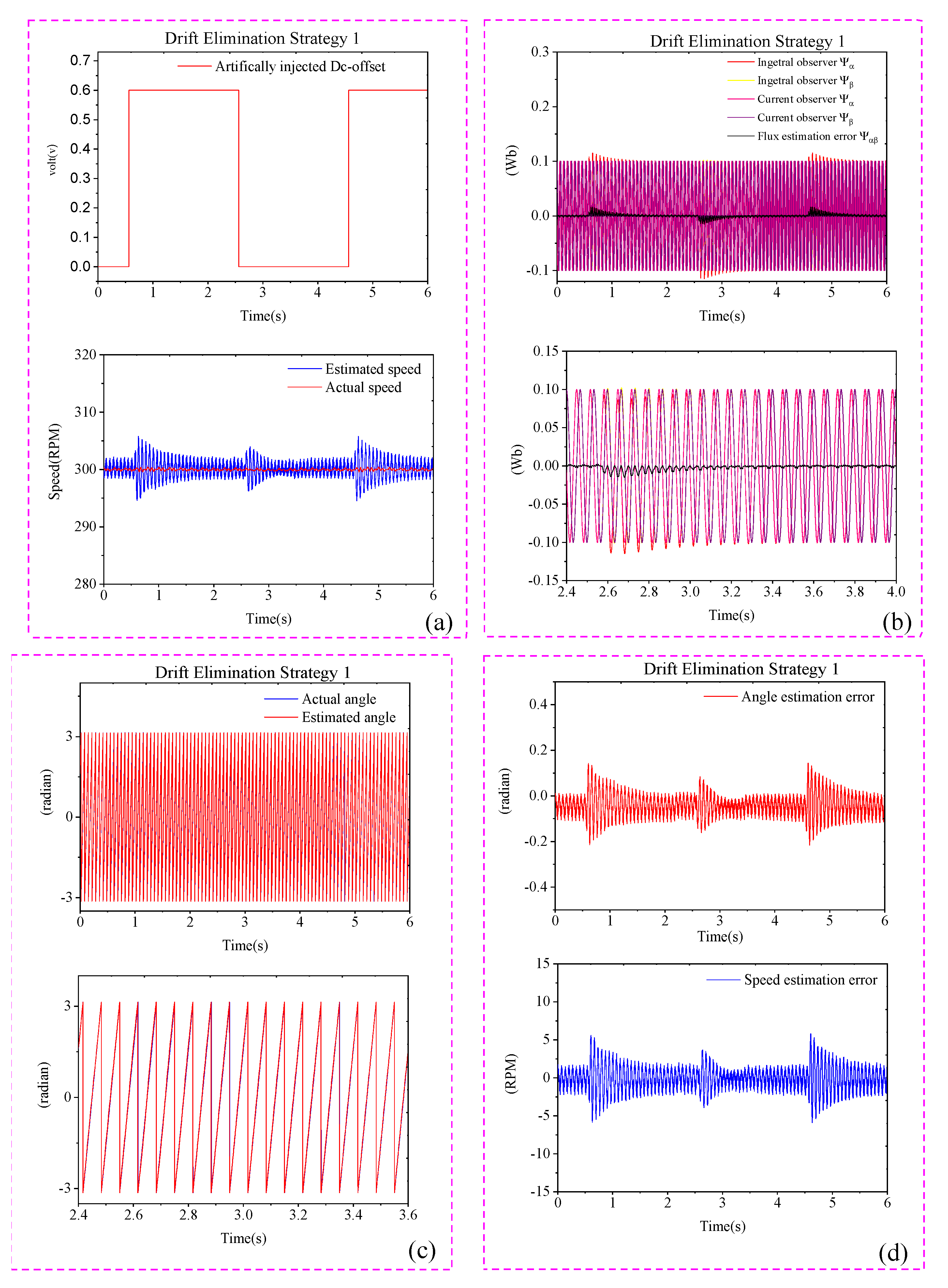
It is well known that the Doff is a severe issue in estimation schemes, as even a small Doff can result in significant oscillations in the estimated quantities. In order to evaluate the efficacy of the DM1 and DM2 drift elimination strategies with Doff, the experimental investigation is conducted with a Doff error component ranging between 0 V and 0.6 V, which is artificially injected into the stator voltage α -axis during the no-load condition. Figure 12 shows the artificially injected Doff error component, rotor speed, flux estimation, rotor position estimation, and position and speed estimation error results using the DM1 method. On the other hand, Figure 13 shows the results with the DM2 method. The experimental outcomes depicted in Figure 12 and Figure 13 indicate that both DM1 and DM2 exhibit good robustness against Doff. In other words, the proposed DM1 and DM2 methods demonstrate that the real-time correction characteristic remains effective even when the Doff error value changes. However, it should be noted that the drift elimination response under DM1 control is slower compared to DM2. On the other hand, DM2 provides a smoother, faster drift elimination response and more stable speed and position estimation.
Figure 14 and Figure 15 illustrate the experimental results of sensorless control using the DM1 and DM2 techniques at 300 rpm. In these experiments, a Doff error component ranging from 1.0 V to 1.5 V is artificially injected into the stator voltage α -axis. The experimental results shown in Figure 14 and Figure 15 indicate that both DM1 and DM2 exhibit strong robustness against the Doff. Due to the ability of DM1 and DM2 to effectively eliminate the DC disturbance, the estimated stator flux experiences almost no Doff.
In the experiment, artificially injected DC disturbance signals with amplitudes of 1.5 V and 1 V were injected into the stator voltage α β -axis to evaluate the DC disturbance rejection capabilities of the DM1 and DM2 drift elimination strategies. Figure 16 illustrates the results obtained with the DM1 method, including artificially injected Doff error component, rotor speed, flux estimation, rotor position estimation, and position and speed estimation errors. Figure 17 illustrates the results obtained with the DM2 method. The experimental outcomes depicted in Figure 16 and Figure 17 indicate that both DM1 and DM2 exhibit good robustness against the Doff. Both algorithms were able to eliminate the DC disturbance, resulting in nearly zero Doff in the estimated stator flux. Based on the experimental tests, it can be concluded that both proposed drift elimination algorithms provide accurate correction performance in the presence of a Doff error component.
Based on the simulation and experimental results presented, the proposed model effectively achieved a good dynamic performance of the IPMSM. The DM2 estimator was more robust than the DM1 estimator. The results show that the system has excellent estimation accuracy under a broad range of situations. An evaluation Table 5 is presented to compare simulation results and experimental results considering Figure 8, Figure 14 and Figure 15, respectively, in order to clarify the enhancements obtained with the proposed strategy.
By comparing the simulation results in Figure 7, Figure 8 and Figure 9 with the experimental results in Figure 12, Figure 13, Figure 14, Figure 15, Figure 16 and Figure 17, it can be noticed that when the computer-based Matlab simulation conditions match the laboratory test conditions, the conclusions drawn from the Matlab simulation and laboratory experiment are identical. However, the waveforms show slight differences, which is attributed to the ideal voltage and current sampling employed in the simulation, which eliminates disturbances from external variables. On the other hand, in the laboratory experiment, the voltage and current are obtained using electrical sensors, which can lead to slightly less accurate measurements due to various sources of interference. As a result, the observed control effects of each variable in the experimental findings may differ partially from those observed in the Matlab simulation. Nevertheless, the validated conclusions remain consistent between the two methods.

6. Conclusions

This paper analyzes and investigates the effects of the DC offset voltage on the performance of a voltage model flux estimation integrated PLL speed-controlled IPMSM drive system:
I.
Two drift elimination strategies, DM1 and DM2, have been devised to tackle the challenges associated with the basic integrators used for motor flux estimations.
II.
Both strategies aim to eliminate the Doff and drift from acquisition channels; as well, the initial flux-vector errors are eliminated. However, DM2 utilizes a self-adapting controller, leading to superior steady-state and dynamic performance compared to DM1.
  • The following major findings are highlighted as follows:
    (1)
    This algorithm is highly efficient in sensorless IPMSM drive systems when the IPMSM flux fluctuates during operation.
    (2)
    Both observers mentioned in this paper are sensorless as they do not rely on the rotor’s speed measurement.
    (3)
    They are unaffected by speed inaccuracies during estimation and are exceptionally resistant to drift and Doff in the measurement process.
    (4)
    The presented simulations and experimental findings demonstrate that the proposed flux linkage observer with Doff compensator feedback loop is suitable for achieving high-accuracy sensorless control of both fixed and dynamic speed trajectories.
    (5)
    This robust solution is applicable to all AC motors with sinusoidal flux distribution across a wide speed range, making it suitable for sensorless control applications as well.

Author Contributions

Conceptualization, C.X. and S.U.R.; methodology, C.X.; software, S.U.R.; validation, C.X. and S.U.R.; formal analysis, C.X.; investigation, S.U.R.; resources, C.X.; data curation, C.X.; writing—original draft preparation, C.X. and S.U.R.; writing—review and editing, C.X. and S.U.R.; visualization, C.X. and S.U.R.; supervision, C.X.; project administration, C.X.; funding acquisition, C.X. All authors have read and agreed to the published version of the manuscript.

Funding

This research received no external funding.

Data Availability Statement

All the data are shown in the tables and figures of this paper.

Conflicts of Interest

The authors declare no conflict of interest.

References

  1. Shah, S.H.; Wang, X.; Abubakar, U.; Gao, P. Experimental Investigation of Noise and Vibration in a Multi-Three Phase Unit Interior Permanent Magnet Synchronous Machine with Open-Circuit Fault Conditions. J. Electr. Eng. Technol. 2022, 17, 2789–2800. [Google Scholar] [CrossRef]
  2. Datta, S.; Chandra, A.; Chowdhuri, S. High Performance Sensor-Less V/f Control of Surface PMSM in Voltage Vector Plane with ZVV Injection and SMO-Based Position Estimation Method. Electr. Eng. 2021, 104, 657–666. [Google Scholar] [CrossRef]
  3. Agarlita, S.; Coman, C.; Andreescu, G.; Boldea, I. Stable V/f Control System with Controlled Power Factor Angle for Permanent Magnet Synchronous Motor Drives. IET Electr. Power Appl. 2013, 7, 278–286. [Google Scholar] [CrossRef]
  4. Baratieri, C.L.; Pinheiro, H. An I/F starting method for smooth and fast transition to sensorless control of BLDC motors. In Proceedings of the Brazilian Power Electronics Conference, Gramado, Brazil, 27–31 October 2013; pp. 836–843. [Google Scholar]
  5. Ning, B.; Zhao, Y.; Cheng, S. An Improved Sensorless Hybrid Control Method of Permanent Magnet Synchronous Motor Based on I/F Start-up. Sensors 2023, 23, 635. [Google Scholar] [CrossRef] [PubMed]
  6. Xie, G.; Lu, K.; Dwivedi, S.K.; Rosholm, J.R.; Blaabjerg, F. Minimum-Voltage Vector Injection Method for Sensorless Control of PMSM for Low-Speed Operations. IEEE Trans. Power Electron. 2016, 31, 1785–1794. [Google Scholar] [CrossRef]
  7. Almarhoon, A.H.; Zhu, Z.Q.; Xu, P. Improved Rotor Position Estimation Accuracy by Rotating Carrier Signal Injection Utilizing Zero-Sequence Carrier Voltage for Dual Three-Phase PMSM. IEEE Trans. Ind. Electron. 2017, 64, 4454–4462. [Google Scholar] [CrossRef]
  8. Zhou, R.; Hu, C.; Wang, Z.; He, S.; Zhu, Y. Nonlinearity Compensation and High-Frequency Flexibility Suppression Based RIC Method for Precision Motion Control Systems. IEEE Trans. Ind. Inform. 2023, 19, 1332–1342. [Google Scholar] [CrossRef]
  9. Wang, Z.; Fei, J. Fractional-Order Terminal Sliding-Mode Control Using Self-Evolving Recurrent Chebyshev Fuzzy Neural Network for MEMS Gyroscope. IEEE Trans. Fuzzy Syst. 2022, 30, 2747–2758. [Google Scholar] [CrossRef]
  10. Kivanc, O.C.; Ozturk, S.B. Sensorless PMSM Drive Based on Stator Feedforward Voltage Estimation Improved with MRAS Multiparameter Estimation. IEEE/ASME Trans. Mechatron. 2018, 23, 1326–1337. [Google Scholar] [CrossRef]
  11. Xiao, D.; Nalakath, S.; Filho, S.R.; Fang, G.; Dong, A.; Sun, Y.; Wiseman, J.; Emadi, A. Universal Full-Speed Sensorless Control Scheme for Interior Permanent Magnet Synchronous Motors. IEEE Trans. Power Electron. 2021, 36, 4723–4737. [Google Scholar] [CrossRef]
  12. Lee, G.B.; Park, J.S.; Lee, S.H.; Kwon, Y.A. High performance sensorless control of PMSM using back-EMF and reactive power. In Proceedings of the International Joint Conference, Seoul, Republic of Korea, 25–27 August 2009; pp. 407–411. [Google Scholar]
  13. Kyung-Rae, C. Jul-Ki Seok Pure-Integration-Based Flux Acquisition with Drift and Residual Error Compensation at a Low Stator Frequency. IEEE Trans. Ind. Appl. 2009, 45, 1276–1285. [Google Scholar] [CrossRef]
  14. Konghirun, M.; Xu, L. A Fast Transient-Current Control Strategy in Sensorless Vector-Controlled Permanent Magnet Synchronous Motor. IEEE Trans. Power Electron. 2006, 21, 1508–1512. [Google Scholar] [CrossRef]
  15. Xin, Z.; Zhao, R.; Blaabjerg, F.; Zhang, L.; Loh, P.C. An Improved Flux Observer for Field-Oriented Control of Induction Motors Based on Dual Second-Order Generalized Integrator Frequency-Locked Loop. IEEE J. Emerg. Sel. Top. Power Electron. 2017, 5, 513–525. [Google Scholar] [CrossRef]
  16. Choi, J.; Nam, K.; Bobtsov, A.A.; Ortega, R. Sensorless Control of IPMSM Based on Regression Model. IEEE Trans. Power Electron. 2019, 34, 9191–9201. [Google Scholar] [CrossRef]
  17. Jo, G.-J.; Choi, J.-W. Gopinath Model-Based Voltage Model Flux Observer Design for Field-Oriented Control of Induction Motor. IEEE Trans. Power Electron. 2019, 34, 4581–4592. [Google Scholar] [CrossRef]
  18. Holtz, J. Sensorless Control of Induction Machines—With or without Signal Injection? IEEE Trans. Ind. Electron. 2006, 53, 7–30. [Google Scholar] [CrossRef] [Green Version]
  19. Holtz, J. Juntao Quan Drift- and Parameter-Compensated Flux Estimator for Persistent Zero-Stator-Frequency Operation of Sensorless-Controlled Induction Motors. IEEE Trans. Ind. Appl. 2003, 39, 1052–1060. [Google Scholar] [CrossRef]
  20. Hinkkanen, M.; Luomi, J. Modified Integrator for Voltage Model Flux Estimation of Induction Motors. IEEE Trans. Ind. Electron. 2003, 50, 818–820. [Google Scholar] [CrossRef] [Green Version]
  21. Yousefi-Talouki, A.; Pescetto, P.; Pellegrino, G.; Boldea, I. Combined Active Flux and High-Frequency Injection Methods for Sensorless Direct-Flux Vector Control of Synchronous Reluctance Machines. IEEE Trans. Power Electron. 2018, 33, 2447–2457. [Google Scholar] [CrossRef]
  22. Lin, T.C.; Zhu, Z.Q.; Liu, J.M. Improved Rotor Position Estimation in Sensorless-Controlled Permanent-Magnet Synchronous Machines Having Asymmetric-EMF With Harmonic Compensation. IEEE Trans. Ind. Electron. 2015, 62, 6131–6139. [Google Scholar] [CrossRef]
  23. Koteich, M. Flux estimation algorithms for electric drives: A comparative study. In Proceedings of the 2016 3rd International Conference on Renewable Energies for Developing Countries (REDEC), Zouk Mosbeh, Lebanon, 13–15 July 2016; pp. 1–6. [Google Scholar]
  24. Lu, Q.; Zhu, X.; Quan, L.; Zuo, Y.; Du, S. Rotor Position Estimation Scheme with Harmonic Ripple Attenuation for Sensorless Controlled Permanent Magnet Synchronous Motors. IET Electr. Power Appl. 2018, 12, 1200–1206. [Google Scholar] [CrossRef]
  25. Pravica, L.; Jukić, F.; Bariša, T.; Stipetić, S. Interior permanent magnet wind generator torque estimation considering low-pass filter phase shift compensation. In Proceedings of the 2018 International Symposium on Industrial Electronics (INDEL), Banja Luka, Bosnia and Herzegovina, 1–3 November 2018. [Google Scholar]
  26. Wang, H.; Yang, Y.; Ge, X.; Zuo, Y.; Yue, Y.; Li, S. PLL- and FLL-Based Speed Estimation Schemes for Speed-Sensorless Control of Induction Motor Drives: Review and New Attempts. IEEE Trans. Power Electron. 2022, 37, 3334–3356. [Google Scholar] [CrossRef]
  27. Jiang, Y.; Xu, W.; Mu, C. Improved SOIFO-based rotor flux observer for PMSM sensorless control. In Proceedings of the IECON 2017-43rd Annual Conference of the IEEE Industrial Electronics Society, Beijing, China, 29 October–1 November 2017. [Google Scholar]
  28. Zhao, R.; Xin, Z.; Loh, P.C.; Blaabjerg, F. A Novel Flux Estimator Based on Multiple Second-Order Generalized Integrators and Frequency-Locked Loop for Induction Motor Drives. IEEE Trans. Power Electron. 2017, 32, 6286–6296. [Google Scholar] [CrossRef]
  29. Xu, W.; Jiang, Y.; Mu, C.; Blaabjerg, F. Improved Nonlinear Flux Observer-Based Second-Order SOIFO for PMSM Sensorless Control. IEEE Trans. Power Electron. 2019, 34, 565–579. [Google Scholar] [CrossRef] [Green Version]
  30. Jiang, Y.; Xu, W.; Mu, C.; Zhu, J.; Dian, R. An Improved Third-Order Generalized Integral Flux Observer for Sensorless Drive of PMSMs. IEEE Trans. Ind. Electron. 2019, 66, 9149–9160. [Google Scholar] [CrossRef]
  31. Silva, C.; Asher, G.M.; Sumner, M. Hybrid Rotor Position Observer for Wide Speed-Range Sensorless PM Motor Drives including Zero Speed. IEEE Trans. Ind. Electron. 2006, 53, 373–378. [Google Scholar] [CrossRef]
  32. Angelone, G.; Del Pizzo, A.; Spina, I.; Vasca, F. Model predictive control for PMSM with flux-current nonlinear maps. In Proceedings of the 2014 International Symposium on Power Electronics, Electrical Drives, Automation and Motion, Ischia, Italy, 18–20 June 2014. [Google Scholar]
  33. Idris, N.R.N.; Yatim, A.H.M. An Improved Stator Flux Estimation in Steady-State Operation for Direct Torque Control of Induction Machines. IEEE Trans. Ind. Appl. 2002, 38, 110–116. [Google Scholar] [CrossRef]
Figure 1. IPMSM sensorless control using rotor flux estimation.
Machines 11 00769 g001
Figure 2. Diagram of IPMSM voltage model for rotor speed and position estimation.
Machines 11 00769 g002
Figure 3. Design of flux estimator combined with PLL for the motion-sensorless system of IPMSM: (a) drift elimination strategy 1; (b) drift elimination strategy 2.
Machines 11 00769 g003
Figure 4. Schematic diagram of the PI controller’s estimation error for e ^ d c .
Machines 11 00769 g004
Figure 5. Schematic diagram of the PI controller’s estimation for e ^ d c .
Machines 11 00769 g005
Figure 6. Schematic representation of overall motion-sensorless control system.
Machines 11 00769 g006
Figure 7. Matlab Simulation results with constant speed (300 r/min) under the α -axis voltage disturbance (0 V and 0.6 V). (a) Artificially injected Doff and DC-drift estimation error, DM1, and DM2. (b) Speed and position estimation error, DM1, and DM2. (c) Observed speed estimation, DM1, and DM2. (d) Estimation fluxes and the errors of estimated fluxes, DM1, and DM2.
Machines 11 00769 g007aMachines 11 00769 g007b
Figure 8. Simulation results with constant speed (300 r/min) under the α -axis voltage disturbance (1 V and 1.5 V). (a) Artificially injected Doff and DC-drift estimation error, DM1, and DM2. (b) Speed and position estimation error, DM1, and DM2. (c) Observed speed estimation, DM1, and DM2. (d) Estimation fluxes and the errors of estimated fluxes, DM1, and DM2.
Machines 11 00769 g008aMachines 11 00769 g008b
Figure 9. Simulation results with constant speed (300 r/min) under the α β -axis voltage disturbance. (a) Artificially injected Doff and DC-drift estimation error, DM1, and DM2. (b) Speed and position estimation error, DM1, and DM2. (c) Observed speed estimation, DM1, and DM2. (d) Estimation fluxes and the errors of estimated fluxes, DM1, and DM2.
Machines 11 00769 g009aMachines 11 00769 g009b
Figure 10. Structure diagram of real-time simulation experimental system for IPMSM based on dSPACE.
Machines 11 00769 g010
Figure 11. IPMSM experimental platform based on dSPACE.
Machines 11 00769 g011
Figure 12. Experimental results of drift elimination strategy 1 with 300 RPM speed under the α -axis voltage disturbance (0 V and 0.6 V). (a) Artificially injected Doff and speed estimation; (b) flux estimation and its enlarged view; (c) angle estimation and its enlarger view; (d) angle and speed estimation errors.
Machines 11 00769 g012
Figure 13. Experimental results of drift elimination strategy 2 with 300 RPM speed under the α -axis voltage disturbance (0.6 V and 0 V). (a) Artificially injected Doff and speed estimation; (b) flux estimation and its enlarged view; (c) angle estimation and its enlarger view; (d) angle and speed estimation errors.
Machines 11 00769 g013
Figure 14. Experimental results of drift elimination strategy 1 with 300 RPM speed under the α -axis voltage disturbance (1.0 V to 1.5 V). (a) Artificially injected Doff and speed estimation; (b) flux estimation and its enlarged view; (c) angle estimation and its enlarger view; (d) angle and speed estimation errors.
Machines 11 00769 g014
Figure 15. Experimental results of drift elimination strategy 2 with 300 RPM speed under the α -axis voltage disturbance. (a) Artificially injected Doff and speed estimation; (b) flux estimation and its enlarged view; (c) angle estimation and its enlarger view; (d) angle and speed estimation errors.
Machines 11 00769 g015
Figure 16. Experimental results of drift elimination strategy 1 with 300 RPM speed under the α β -axis voltage disturbance. (a) Artificially injected Doff and speed estimation; (b) flux estimation and its enlarged view; (c) angle estimation and its enlarger view; (d) angle and speed estimation errors.
Machines 11 00769 g016
Figure 17. Experimental results of drift elimination strategy 2 with 300 RPM speed under the α β -axis voltage disturbance. (a) Artificially injected Doff and speed estimation; (b) flux estimation and its enlarged view; (c) angle estimation and its enlarger view; (d) angle and speed estimation errors.
Machines 11 00769 g017
Table 1. The specifications for the 7.5 kW IPMSM drive system.
ParametersValues
Rated power7.5 KW
Rated current34 A
Rated speed3000 (r/min)
Poles3
Stator phase resistance0.1 Ω
Flux linkage0.10 Wb
d/q-axis inductance0.348/0.558 mH
Moment of inertia 0.35 k·g·m2
Table 2. DM2, with constant speed trajectory.
Artificially added Doff 0.6 V at 2 sStrategy 1Strategy 2
SSPEE (degree)00
SSSEE (r/min)00
TSSPEE (s)2.00.3
Artificially decrease the Doff from 0.6 to 0 V at 4 sStrategy 1Strategy 2
SSPEE (degree)00
SSSEE (r/min)00
TSSPEE (s)2.00.3
Table 3. Steady state errors of DM1 and DM2, with variable DC-drift error (1V and 1.5V) and constant speed trajectory.
Artificially added Doff 1 V at 2 sStrategy 1Strategy 2
SSPEE (degree)00
SSSEE (r/min)00
TSSPEE (s)2.00.3
Artificially added Doff 1.5 V at 4 sStrategy 1Strategy 2
SSPEE (degree)00
SSSEE (r/min)00
TSSPEE (s)2.00.3
Table 4. Steady state errors of DM1 and DM2, with variable DC-drift error component and constant speed trajectory.
Artificially added Doff 1 V under stator voltage α β -axis at 2 sStrategy 1Strategy 2
SSPEE (degree)00
SSSEE (r/min)00
TSSPEE (s)2.00.3
Artificially added Doff 1.5 V under stator voltage α β -axis at 4 sStrategy 1Strategy 2
SSPEE (degree)00
SSSEE (r/min)00
TSSPEE (s)2.00.3
Table 5. Comparison of steady-state errors for DM1 and DM2, with constant speed trajectory.
MethodSimulationExperiment Average   Error   ( % )
SSSEE
(r/min)
SSPEE
(Degree)
SSSEE
(r/min)
SSPEE
(Degree)
SSSEE
(r/min)
SSPEE
(Degree)
DM1 0 0 1.5 7.3 0.5 % 2 %
DM2 0 0 1.4 4.5 0.4 % 1.2 %
Disclaimer/Publisher’s Note: The statements, opinions and data contained in all publications are solely those of the individual author(s) and contributor(s) and not of MDPI and/or the editor(s). MDPI and/or the editor(s) disclaim responsibility for any injury to people or property resulting from any ideas, methods, instructions or products referred to in the content.

