1. Introduction
In response to strict efficiency goals, some electric motor companies proposed the three-phase Line-Start Permanent Magnet Synchronous Motors (LSPMSM) as an efficient alternative for replacement of older induction motors, since LSPMSMs are able to start directly connected to the grid [
1,
2,
3,
4].
LSPMSMs are hybrid rotor synchronous motors combining the characteristics of permanent magnet synchronous motors (PMSMs) and the characteristics of induction motors (IMs) in a single rotor, as can be seen in
Figure 1. Under healthy and balanced supply voltage conditions, at steady-state synchronous speed, LSPMSMs work as PMSMs and no current flows through the rotor bars. The rotor cage allows LSPMSMs to start and overcome large torque oscillations as mains-fed induction motors.
The increasing importance of LSPMSMs in modern industry and their use in highly critical applications demands the development of proper approaches for fault diagnostics.
As any AC electric motor, LSPMSMs can present several types of faults. Highly related with aging mechanisms, the stator faults represent 21–37% of all faults in AC machines and are one of the major causes for three-phase AC motors [
5,
6,
7].
The subject of on-line fault detection in LSPMSMs has been addressed in the literature, although most published works are focused on rotor faults and demagnetization. Regarding the rotor faults, in [
8,
9], the authors present an investigation on the effect of the static eccentricity fault in LSPMSM. The study is carried out by using a finite element model (FEM), in which the motor current signals were extracted at steady-state conditions. By applying the power density spectrum of such signals, the static eccentricity-related harmonics are analyzed, and a set of frequency patterns are proposed for fault diagnostics. Another eccentricity fault analysis report is conducted in [
10]. Once again, the analysis is performed by means of the signals calculated from FEM. This report presents a transient analysis of the static, dynamic, and mixed eccentricity effects on the motor speed, load torque, and flux density distribution signals. In [
11], the authors conduct a study on both stator and rotor slots openings in a LSPMSM, under asymmetrically distributed squirrel cage bars, to optimize the motor performance. The analysis is focused on the motor’s back-electromotive force (back-EMF) and phase current signals. The rotor broken bar detection is carried out in [
12], by assessing both mean and root mean square values of the transient current signals, in the time domain. Afterwards, resorting to Tuckey’s technique, a statistical evaluation of such features is performed to monitor the condition of the motor. Experimental results carried out in a physical LSPSMS showed the effectiveness of the method.
When it comes to demagnetizing faults, in [
13], the authors propose a new rotor shape design for a single-phase LSPMSM to reduce the back-EMF caused by the irreversible demagnetization. This achievement was undertaken with the help of the FEM analysis, where the characteristics of both the magnetic core and permanent magnets were considered. An investigation on the decaying of the magnet’s proprieties in four different LSPMSMs, with different rotor configurations, is undertaken in [
14] by means of FEM analysis. Based on this analysis, the authors propose the adoption of a configuration with dual cages and magnetic barriers to shield the permanent magnets and keep the best operation performance. In [
15], the analysis of the influence of the motor initial load torque and moment of inertia on the permanent magnets demagnetizing is carried out in a LSPMSM, under three-phase short-circuit fault (or phase-to-ground) and out-of-synchronism fault. Once again, this analysis was performed by resorting to FEM analysis. Another report focused on the demagnetizing faults encountered in [
16]. In this case, the authors propose a current injection method to diagnose and discriminate local demagnetizing faults from dynamic eccentricity faults in a LSPMSM. Conducted by making use of the FEM analysis, the method consists of injecting an AC signal in the d-axis, which in turn alters the magnetic permeability symmetry. The faults are therefore detected and discriminated by analyzing the voltage signals of an arrangement of search coils placed in the interior of the stator slots.
Concerning the stator faults, in particular the early stage of inter-turn short-circuits (ITSC) faults, the authors proved in [
17] that, for the case of a balanced supply voltage, the harmonic component of the Extended Park Vector Approach (EPVA) of the stator current at twice the supply frequency can be used as a reliable indicator for fault detection. In [
18], an approach is presented to monitor and track a fault harmonic component. Based on the analysis of the transient motor current signals through the combination of the application of Gabor transform, ensemble empirical mode decomposition, and Kullback–Leibler divergence, the authors show that the ITSC faults can be diagnosed in a LSPMSM operating under both variable speed and load torque conditions. A frequency analysis of the acoustic signals is performed in [
19]. This analysis is conducted in a LSPMSM under ITSC faults. By applying the Fast Fourier Transform to investigate the spectrum components of such signals, the authors conclude that the frequency components of above 9 kHz are fault indicators for the case of no-load motor operation, whereas those below this frequency, are fault indicators for the full-load motor operation.
Several other fault diagnostic approaches, mostly based on Artificial Neural Networks (ANN), can be found in the literature. For instance, in [
20], an artificial intelligence method based on ANN is proposed for ITSCF fault diagnostics. The technique consists of using a set of time-domain and frequency-domain features, extracted from both stator currents and voltages. Such features are thereby the inputs of the multilayer feed-forward ANN, and the outputs serve as fault indicators. The experimental results reveal 96% overall accuracy in detecting different severities of ITSC faults in a LSPMSM operating under different load torque conditions. In [
21], the same authors use the same background to diagnose ITSC faults, as well as to locate the faulty phase, claiming high rates of accuracy in fault severity evaluation (100%) and faulty phase location (93.125%). Another method reported by the same authors suggests, in [
22], the use of a Convolutional ANN, where both simulated and experimental phase currents serve as inputs. Presenting different load conditions and fault severities, the authors claim that the method also demonstrates high accuracy.
A common point that all these reports show is the fact that all consider balanced supply voltage conditions.
The subject of on-line detection of ITSC faults in the stator windings of both IMs and PMSMs has also been addressed in the literature, and several techniques have proved their effectiveness regarding fault detection. However, PMSMs are usually fed by power electronic converters that guarantee a balanced supply voltage [
23]. Moreover, in the presence of incipient ITSC faults or unbalanced supply voltages (USV), a current will flow in the rotor cage, leading to a different performance of LSPMSMs as compared to PMSMs, and the rotor will continue to run synchronously, differently from IMs [
5].
The impact of USV conditions on the performance of a heathy LSPMSM was addressed in [
24], however, the authors focus on the impact of the USV on the motor efficiency. Thus, the inter-turn short-circuits fault diagnostic in LSPMSMs, under unbalanced supply voltage conditions, has never been addressed in the literature.
This paper presents an approach for inter-turn short-circuits fault diagnostics in the stator windings of LSPMSMs under USV conditions, based on the analysis of the admittance at a frequency twice the supply frequency in the Park’s reference frame. Experimental results prove its effectiveness for different load torque levels, unbalanced supply voltage values, and different severity cases.
2. ITSC Faults Incorporation in the Line-Start Permanent Magnet Synchronous Motor Model
When it comes to fault analysis in three-phase electric motors, the stationary reference frame (
abc) is more suitable over the rotating rotor reference frame (
dq) since the former provides the opportunity to easily choose the phase where the ITSC fault occurs. Considering
N as the total number of turns per stator phase, in the event of a short-circuit fault, the faulty phase winding can be divided into a healthy part, with
Nh turns, and a faulty part, with
Nsc turns. Thus, the number of short-circuit turns in the faulty phase can be related with the total number of turns per phase as [
5]:
where
is the shorted turns ratio that varies within the value range between 0 and 1.
Since the short-circuit path is usually not perfect, a fault contact resistor (Rf) is considered to be connected in parallel with the faulty turns.
Considering the phase shift of 120 degrees between phases, the existence the LSPMSM model featuring ITSC faults is composed of both electric and mechanical equations. Therefore, the stator and rotor electric circuit equations, in
abc reference frame coordinates, are defined as follows, respectively [
5]:
where
,
, and
are the stator phase voltages and the stator and rotor phase currents vectors, respectively,
and
are the stator and rotor resistance, respectively,
and
are the flux linkages of the stator and rotor, respectively, and
is back-electromotive force. Both stator and rotor flux linkages, and the back-electromotive force are given by, respectively:
and
where
and
denote the stator and rotor leakage inductances, respectively,
and
are stator and rotor self and mutual inductances, respectively,
and
are the mutual inductances between the stator and rotor and vice versa, respectively,
is the stator linkage flux generated by the permanent magnets,
is the number of poles pair, and
is the mechanical angular speed.
The dynamic mechanical balance in the shaft, which characterize the mechanical equation, is described by:
where
is the moment of inertia,
is the load torque,
is the torque for self-ventilation and friction, and
and
are the torque developed in the rotor cage bars, and the torque due to the permanent magnets, respectively, and are given by:
and
Further details about the model composition and inductance matrix calculation can be encountered in [
5].
3. Line-Start Permanent Magnet Synchronous Motor Admittance in the Park’s Reference Frame
Based on the equivalent circuit of the induction machine (IM) recommended by IEEE and the conventional permanent magnet synchronous motor (PMSM) equivalent circuit, line-started permanent magnet synchronous motors (LSPMSM) are represented by a hybrid, per phase, equivalent circuit model presented in
Figure 2, where [
2]:
RS—per-phase stator winding resistance;
LlS—per-phase stator leakage inductance;
RR—per-phase rotor circuit resistance;
LlR—per-phase rotor leakage inductance;
Ef—back-EMF induced in the stator phase winding by the rotor PMs;
Lm—per-phase stator magnetizing inductance.
s—Motor slip
It is possible to notice in
Figure 2 some technical features of the squirrel cage (
Llr and
RR) and of the rotor magnets (
Ef).
In case of USV, the supply voltage system can be decomposed into a set of symmetrical components (positive, negative, and zero sequences). Considering the Fortescue transform as:
In which
,
, and
are the voltage phasors of, respectively, the positive, the negative, and zero components of phase
A voltage and
are the phase voltage phasors,
. The other phases voltage symmetrical components are obtained as:
Considering a LSPMSM operating without neutral connection at synchronous speed, that is
s = 0 and
I0 = 0, the heathy motor phase current can be obtained based on the per-phase equivalent circuit for both positive,
, and negative,
, components, as presented in
Figure 3.
Based on this, it is possible to notice that the heathy motor impedance for the negative symmetrical component remains unchanged, at synchronous speed, and it is not dependent on both load torque and unbalance supply voltage level.
Applying the Park’s transformation to the phase voltage and current based on their symmetrical components one obtains:
As it is well known, the Extended Park Vector Approach (EPVA) is a Fast Fourier Transform (FFT) analysis of the AC component of the modulus of either voltage, , or current, , Park’s Vector.
Under unbalanced three-phase voltage or current systems, due to the USV or the inter-turn short-circuit, the average values of either or are due to the positive symmetrical component and the 2fs (100 Hz) harmonic component is due to the negative symmetrical component.
Under USV, increases, resulting in the development of a breaking torque in the rotor cage compensated by a small increase of the motor torque developed due to the DC component of and .
As for the negative symmetrical component, in healthy LSPMSMs, the
of the supply voltage will lead to the appearance of a
current component. Since the electromotive force due to the rotor PMs only interacts with the DC component of
, the positive symmetrical component, the admittance for the 100 Hz harmonic component,
, that established the relation between the
of the supply voltage and the
, will be related to the interaction of the stator windings and the rotor cage. Considering an admissible unbalanced level, the admittance for the 100 Hz harmonic component,
, defined as:
will be constant and load independent if the motor rotational speed remains constant. A small dependency with the load is expected since the 100 Hz components causes torque ripple and a small speed oscillation.
In case of ITSC faults, the three-phase impedance becomes unbalanced, as well as the back-EMF induced in the stator phases by the rotor PMs and the admittance for the 2fs harmonic component will change from its healthy value.
The option for the use of the admittance instead of the impedance is due to the possibility of zero value of in case of both USV and ITSC faults.
For a complete characterization of the impact of the USV level in the admittance for the 100 Hz harmonic component, the USV level was quantified by the Voltage Unbalance Factor (VUF), defined according to the International Electrotechnical Commission (IEC) as the ratio between the negative and positive symmetrical components of the voltage, as:
4. Results
The proposed fault diagnostic technique was evaluated by both simulation and experimental tests. The healthy and faulty LSPMSM simulation was carried out in the Matlab/Simulink environment, based on the model presented in
Section 2, and in [
5].
A LSPMSM, 50 Hz, four-pole, 1.1 kW, 1500 rpm, manufactured by WEG, with the parameters present in
Table 1, obtained through a set of experimental tests as in [
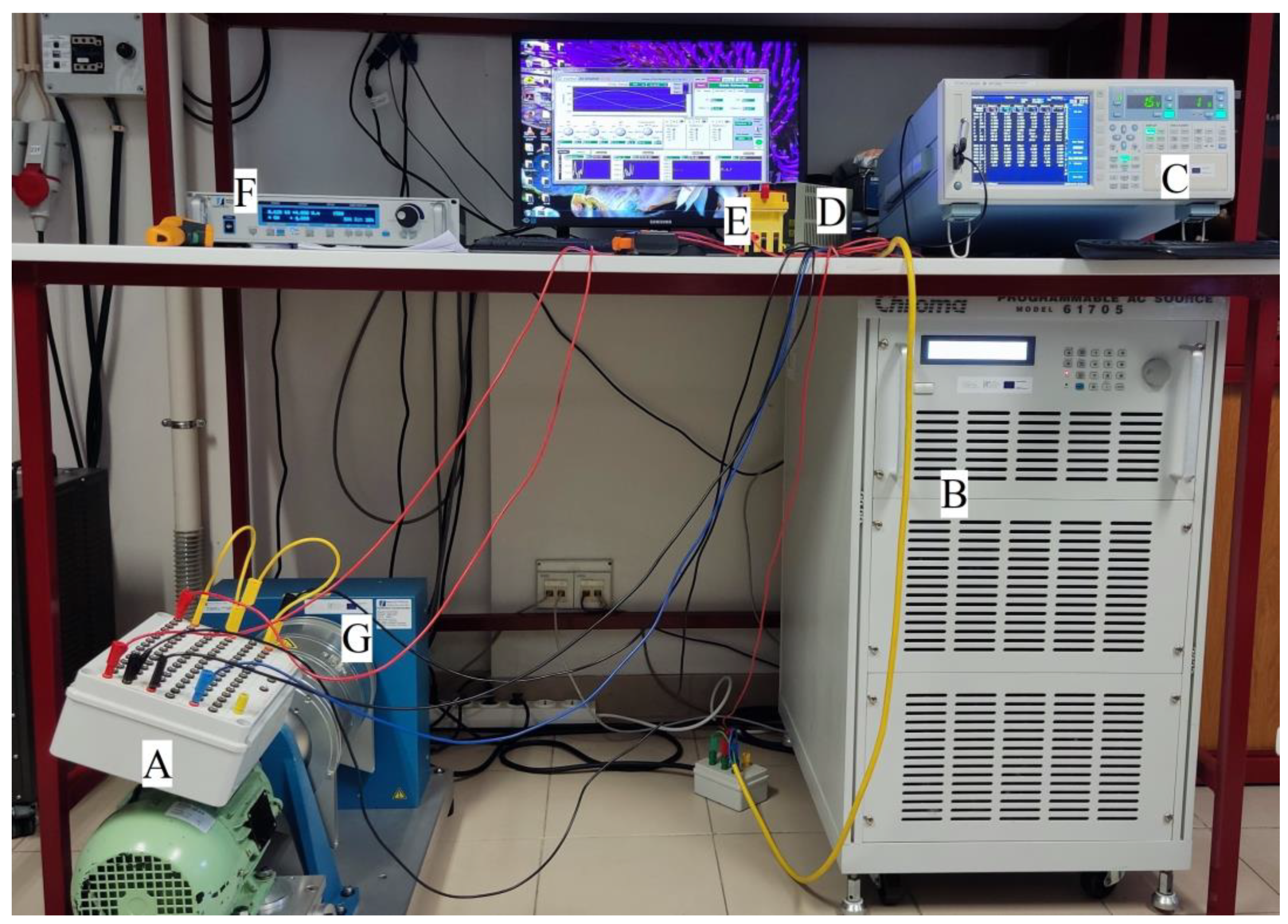
25], was used to validate the proposed approach. As shown in
Figure 4, the motor was star-connected, fed by a Chroma AC Programmable source, model 61705, and loaded by means a MAGTROL Hysteresis Dynamometer, model HD-815-8NA, controlled by the MAGTROL Dynamometer Controller, model DSP7000. The data acquisition instrumentation was performed by means of a YOKOGAWA precision power analyser, model WT1800, configured for a sample rate of 8000 samples per second.
The fault current was limited by a fault resistance, Rf, of 3.5 Ω, connected in parallel with the short-circuited turns. Its value was chosen to remain constant in all tests and was simultaneously high enough to prevent motor integrity and sufficiently low to provide an effect strong enough to be easily visualized.
As usual in industry, only two line currents,
IA and
IB, and two line voltages,
UAB and
UBC, were directly measured. The remaining current and voltage are obtained by:
and
The data analysis was performed in the Matlab environment according to the following procedure: the EPVA of both phase currents and line voltages are obtained to extract the 100 Hz (2fs) component amplitude; then, the 100 Hz admittance is calculated through (12).
The three-phase LSPMSM is fed by a three-phase supply under balanced and unbalanced supply voltage conditions for three levels of load torque of 2 Nm, 4 Nm, and 7 Nm.
In the experimental tests, the AC Programmable source was set to create the unbalance in the supply voltages. Six levels of USV were considered, four with the unbalance introduced in the faulty phase and two in a healthy phase, as expressed in
Table 2. Note that for the six levels of USV presented in
Table 2, the supply voltage also presents a zero sequence component; however, the motor phase current is only related to both positive and negative sequence components since the motor has no neutral connection.
As can be seen in
Figure 5, the 100 Hz admittance in healthy conditions remains almost independent of the load level or the VUF. Changes in the healthy admittance, and differences between simulation and experimental results, are expected and due to the intrinsic asymmetries of the motor [
26].
Moreover, the empirical nature of the parameters values used in the simulation model can introduce some differences between simulation and experimental results.
In case of a short-circuit in phase A, the 100 Hz admittance increases when the VUF angle is 0 because both phenomena contribute to the increase of the faulty phase current. When the VUF angle is π, the 100 Hz admittance decreases due to the short-circuit in phase A since the voltage unbalance promotes a decrease of the faulty phase current and the short-circuit induces an increase in the same phase.
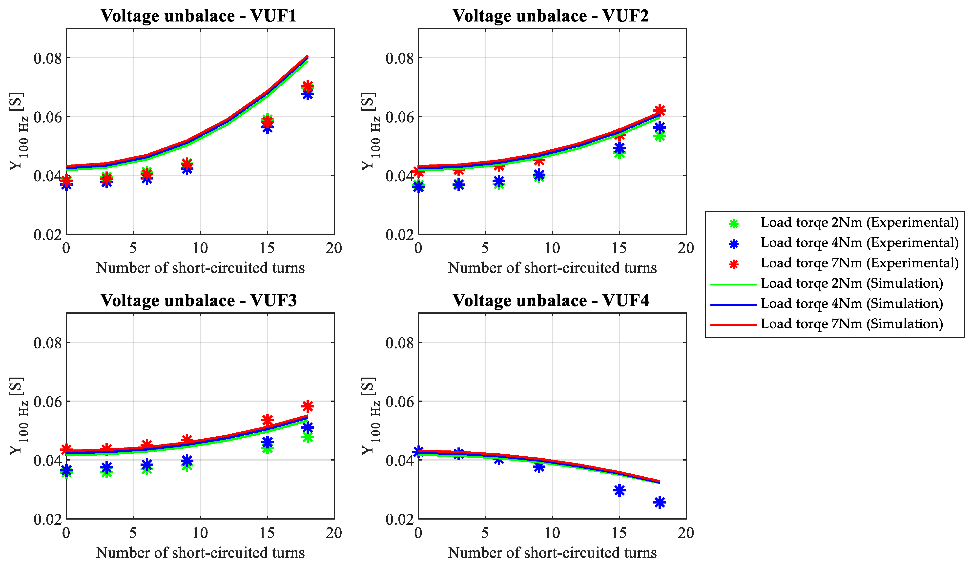
From
Figure 6, one can observe a similar behavior of the 100 Hz admittance. That is, the 100 Hz admittance presents a similar value, in healthy conditions, independent of VUF or load, and will decrease or increase with the fault severity depending on the relation between the VUF angle and the faulty phase.
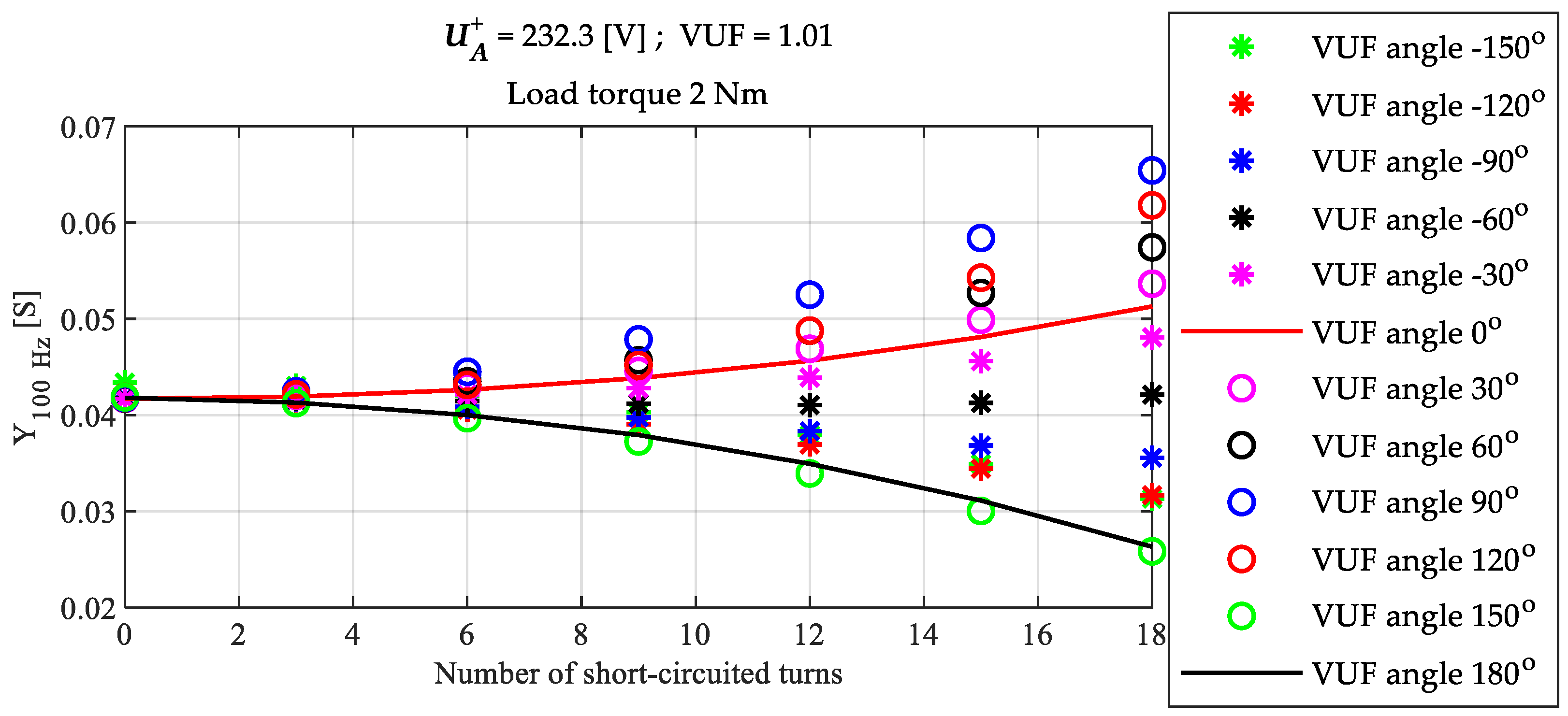
For a better understanding of the relation between the VUF angle, the faulty phase, and the evolution of the 100 Hz admittance, simulations were carried out considering the fault in phase A, with a phase angle of 0°, and different values of VUF angle. In
Figure 7,
Figure 8 and
Figure 9 it is possible to observe that for an angle of around −60° the 100 Hz admittance remains almost constant because of the influence of the positive sequence voltage in the negative sequence current, that exists if the load is unbalanced, compensate the impact of the load unbalance in phase A. For VUF angles between −30° and 120° the 100 Hz admittance increases with increment of the fault severity, and for angles between 150° and −90° the 100 Hz admittance decreases with increment of the fault severity.
It can be also observed that, for the same value of and VUF angle, the impact of both the load torque and the VUF value in the 100 Hz admittance is negligible.
5. Conclusions
This paper presents a new approach for inter-turn short-circuits fault detection in three-phase LSPMSMs operating under USV conditions. The proposed approach allows for the detection and identification of stator faults based on 100 Hz admittance obtained with the EPVA of both voltage and current.
The impact of both VUF value and angle were addressed and highlighted the negative impact in the ability for fault diagnostic whenever the VUF angle is equal to the phase angle minus 60°.
It was proved that the 100 Hz admittance of a healthy motor, related with the negative sequence of both voltage and current, remains almost unchanged with the load and the voltage unbalance factor.
It was also proved that, for the same value of the positive sequence voltage and VUF angle, the impact of both the load torque and the VUF value in the 100 Hz admittance is negligible.
Future work will be carried out to allow for the fault diagnostics when the VUF angle is equal to the phase angle minus 60°, and to obtain a normalized fault indicator independent of the positive sequence voltage and VUF angle.


