Article

Kinematic Analysis of a Spatial Cable-Driven Mechanism and Its Equivalent Hybrid Mechanism for Elliptical Trajectory

1
College of Automotive Engineering, Xiangtan Institute of Technology, Xiangtan 410219, China
2
Department of Mechanical and Vehicle Engineering, Hunan University, Changsha 410082, China
3
College of Mechanical and Electrical Engineering, Hunan Agricultural University, Changsha 410128, China
*
Author to whom correspondence should be addressed.
Machines 2023, 11(7), 710; https://doi.org/10.3390/machines11070710
Submission received: 22 May 2023 / Revised: 22 June 2023 / Accepted: 3 July 2023 / Published: 4 July 2023
(This article belongs to the Collection Machines, Mechanisms and Robots: Theory and Applications)

Abstract

:
In this paper, a spatial cable-driven parallel mechanism in a V-shaped cable arrangement is proposed. It is further simplified as a planar hybrid cable-driven parallel mechanism to analyze its kinematics, which consists of two identical active cable chains and a passive cross-slide mechanism. In order to investigate the degrees of freedom (DoFs) of the hybrid mechanism using screw theory, cable chains are represented as rotational–prismatic–rotational (RPR) chains. The motion pairs of all the chains are denoted according to screw theory. Firstly, the number and the types of DoFs of each chain are determined. Then, the number and the types of DoFs for the hybrid mechanism are calculated. Furthermore, the theoretical result is verified using the modified Grübler–Kutzbach (G-K) formula. It shows that the unique DoF of the equivalent mechanism is a rotation with a continuously changing axis, which is consistent with the V-type cable-driven mechanism with elliptical trajectories. Finally, the kinematics analysis of the cross-slider mechanism driven by two cables is carried out. The length, velocity and acceleration of the cables are obtained from numerical calculation in MATLAB, and the results are demonstrated using ADAMS simulation.

1. Introduction

Cable-driven parallel mechanisms are a special type of parallel mechanism driven by flexible cables, which have been widely used in several applications [1,2,3,4]. One prominent advantage of cable-driven mechanisms is their capability of fast transportation with high payload over a large-span distance. A mobile cable-driven parallel robot proposed in [5] is capable of changing its geometric architecture to increase the wrench-feasible workspace for specific tasks. To improve the mobility of end-users across a river or other civil structures, a cable-suspended robot with merely prismatic DoFs is studied by Castelli in [6]. The singularity analysis of cable-driven parallel robots in a pairwise cable arrangement is performed in [7]. Cable-suspended manipulators can also be used in industrial environments for pick-place operations using a reconfigurable end-effector [8]. Furthermore, a particular application of cable-driven parallel mechanisms is the astronomical observation of deep space. Six cables are utilized to carry a feed-supporting platform over the range of a radius of 250 m for the purpose of collecting out-of-space signals in China [9,10].
In the present paper, a specific cable-driven parallel mechanism, assembled with V-shaped cable units, is proposed to fulfill the need of achieving large rotation for astronomy observation near the workspace boundaries. It will be described in Section 3 in detail. In particular, in observation tasks, a signal receiver of a large radio telescope has to be positioned around the border of workspace with a large rotational angle. However, it was demonstrated that the rotation angle is limited to less than 40 degrees in the present cable configuration [11]. Due to the cable flexibility, a cable-driven parallel configuration in a V-type cable arrangement was adopted, as shown in Figure 1. Khakpour [12] analyzed the features of several V-shaped cable-driven planar manipulators with differential actuation. A basic unit of the V-shaped cable-driven parallel mechanism is the connection of both static and moving platforms with one cable via a pulley. As a result, the position of the attachment points of the moving pulleys follows an elliptical trajectory. A V-shaped configuration (i.e., a V-type configuration) was employed to construct a planar cable-driven robot with a parallelogram arrangement [13]. Based on the geometrical feature of an elliptical trajectory, the proposed cable-driven parallel mechanism is capable of realizing large rotation near the workspace boundary accordingly. The contouring control problem with uncertainty is solved for a five-DoF robotic manipulator [14]. Then, the first issue to be solved for the implementation of the proposed cable-driven robot was to determine the DoFs of the mechanism.
Screw theory plays an important role in the study of robot configuration and freedom type. During the middle of the 20th century, Dimentberg [15] applied screw theory to first analyze the spatial mechanism. Later, Hunt [16] and Duffy [17] made great contributions to screw theory and its applications. Mohamed [18] exploited screw theory to investigate the kinematics of parallel mechanisms. Referring to [19,20,21,22], a breakthrough was made in the generalized method for the DoF analysis of spatial closed-loop mechanisms, especially multi-loop parallel mechanisms using screw theory.
Although screw theory is a versatile method to determine the DoFs of mechanisms, the mechanism has to be composed of only rigid links. To further simplify the kinematic analysis of the spatial cable-driven mechanism, an equivalent planar hybrid mechanism with both rigid links and cables is proposed to implement an elliptical trajectory. The determination of an alternative mechanism is essentially configuration synthesis. Three types of configuration synthesis methods include displacement group theory [23], screw theory [24] and topological theory [25]. Hu proposed the concept of a motion-equivalent parallel mechanism. The study showed that some parallel mechanisms with different structures have the same kinematics and performance. It provides better selection criteria for a specific configuration of parallel mechanisms [26,27,28]. According to screw theory, the kinematic constraint screws of a parallel mechanism are obtained. Then, from the relationship of the constraint screws and the motion screws, the corresponding parallel mechanism with identical motion but different configurations can be identified. In this process, the constraint screws of the mechanism may have changed, but the constraint space remains the same. The kinematic analysis of the present V-shaped cable-driven parallel mechanism is fundamental work for the astronomical application. It paves the way to the establishment of the dynamic modeling and motion control of the cable-driven parallel mechanism in a V-shaped arrangement.
The main contribution of this paper is to propose a new V-shaped cable-driven parallel mechanism for astronomical observation using elliptical trajectories. An equivalent planar hybrid mechanism is presented by investigating the kinematic constraints. The resulting DoF of the simplified hybrid mechanism was derived as a continuously changing axis along a global axis through screw theory. In addition, the kinematic analysis of the hybrid mechanism was performed and demonstrated using ADAMS simulation. The obtained results of the cable length can be applied in the control of the proposed V-shaped cable-driven parallel mechanism. To the knowledge of the authors, there is no literature on the kinematic analysis of the hybrid mechanism using screw theory, which has the potential to design a more complex cable-driven mechanism in a V-shaped cable configuration.
Except for its potential usage in astronomical observation, there are some practical applications with the requirement of an elliptical trajectory. For instance, elliptical trajectory motion is introduced in the field of pick-place industrial applications [29]. Robotic-assisted elliptical training is being widely employed to help patients retain walking ability [30], where the proposed cable-driven mechanism is suitable due to safety.
The rest of the paper is organized as follows: The preliminary definitions on screw theory are introduced in Section 2. The description of the proposed spatial cable-driven parallel mechanism and the equivalent planar hybrid mechanism are illustrated in Section 3. More importantly, the determination of DoFs for the equivalent mechanism was carried out using screw theory. The obtained results validated using the improved G-K formula are in Section 4. In Section 5, the kinematic analysis of the cable-driven cross-slider mechanism was carried out to further verify the DoF of the mechanism, and ADAMS simulation was performed to compare with the theoretical results. Finally, the conclusions obtained are in Section 6.

2. Preliminary on Screw Theory

Spiral, denoted as $, is also referred to as screw, which is represented by a pair of dual vectors ( s , s 0 ) in space:
$ = ( s ; s 0 ) = ( l , m , n ; p , q , r ) ,   s · s 0 0 ,
where s is the main part, and s 0 is the dual part. When the inner product of a pair of dual parts is zero, i.e., s · s 0 = 0 , it means that the spiral degenerates into a line vector.
If the reciprocal product of two screws $ = ( s ; s 0 ) and $r = ( s r ; s r 0 ) is zero:
$ · $ r = s · s r 0 + s r · s 0 =   0 ,
then $ and $r are defined as two reciprocal screws. To calculate DoFs, screws are expressed as motion and constraint screws. For example, $ = ( s ; 0 1 × 3 ) denotes a pure rotation motion or a force vector at the origin of the coordinate system, while $ = ( 0 1 × 3 ; s 0 ) denotes a pure prismatic motion. As $ represents a motion screw, the corresponding $r represents its constraint screw.
Each chain of a parallel mechanism imposes several constraints on the moving platform [31,32]. Moreover, synthesis of the constraint screws of each chain determines the DoFs of the moving platform [33]. All the motion pairs in a chain constitute the motion screw system of the chain. The reciprocal screw of the motion screw system constitutes the constraint screw system of the chain. The constraints of a chain imposed on the moving platform are determined accordingly. The constraint screw system of each chain synthesizes the entire constraint screw system of the mechanism, which represents the constrained DoFs of the parallel mechanism. Thus, the DoFs of the proposed mechanism are finally calculated on the basis of screw theory.

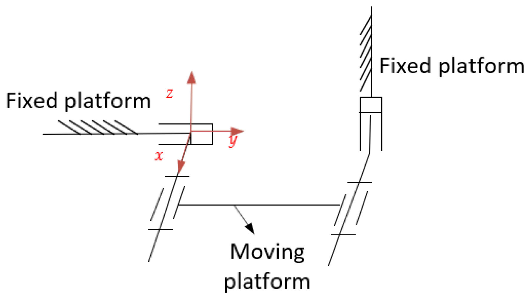
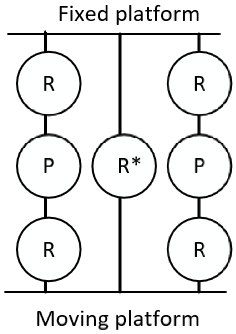
3. Equivalent Rigid Parallel Mechanism

The present cable-driven parallel mechanism consists of a moving platform (1), four V-type cable units (2), a fixed platform (3) and a passive motion chain (4), which is depicted in Figure 2. Each V-type cable unit formed by only one cable connects the moving platform and the fixed platform via a pulley attached on the moving platform. Four pulleys are located in a circular array at an angle of 90 degrees, as illustrated in Figure 2. One end of each cable is connected to a servo-motor directly or a winch, and the other end is fixed to the fixed platform at an anchor point, whose shape is described as ‘V’. The cables are retracted or extended such that an elliptical motion of the moving platform is implemented. There are two mounting approaches for four cable units. One approach corresponds to the case that the plane of the cable is always perpendicular to the moving platform, while the other produces a slope with respect to the moving platform. The passive motion chain consists of a hook hinge and a prismatic joint, which is applied to constrain the feasible motion of the proposed mechanism on Plane 1, as shown in Figure 2. Additionally, the angular bisectors of sectors formed by V-type cable units are limited to being on Plane 1 and Plane 2, respectively. Moreover, due to V-type differential cable arrangement and corresponding constraints imposed by the passive chain, the motion trajectory of the moving platform is limited to being elliptical. It is also noted that only one pair of cable units works actively, while the other pair maintains a constant cable length.
For the convenience of analysis, a planar hybrid cable-driven mechanism for elliptical trajectory is presented to investigate as a simplified mechanism, as shown in Figure 2. Furthermore, a cross-slide rigid mechanism was exploited to substitute V-shaped cable units to achieve elliptical trajectories. According to the cable configuration, two RPR chains were employed to replace the active cable chains, while the passive cable chain was driven by the cross-slide mechanism in Figure 3.
Thus, the simplified planar hybrid cable-driven mechanism is represented by a rigid parallel mechanism of 2RPR-PRRP, as shown in Figure 4, where R denotes rotational pair, and P means prismatic pair.
As there is a closed loop sub-chain, it is necessary to develop the equivalent motion screw system of the cross-slide mechanism (prismatic–rotational–rotational–prismatic, namely, PRRP), and the specific steps are given as follows:
(1)
List the motion screw system of each chain;
(2)
Find the reverse screw of (1);
(3)
The quadratic anti-screw of (2) is solved to obtain kinematic screws of the mechanism allowed by constraint screws.
The closed-loop chain of the cross-slide mechanism is transformed into two sub-chains, which are regarded as 2PR (Prismatic-Rotational) sub-chains. The motion pair of a horizontal sub-chain was selected as the origin of the coordinate system. x axis is located along the axis of rotational pair, y axis is along the motion direction of prismatic pair, and z axis is defined according to the right-hand rule, as shown in Figure 5.
Chain 1 is composed of a prismatic pair and a rotational pair. The motion screw system is given as
$ 11 = ( 0 , 0 , 0 ; 0 , 1 , 0 ) ,   $ 12 = ( 1 , 0 , 0 ; 0 , 0 , 0 ) .
Screws $ 11 and $ 12 represent the prismatic motion along y axis and the rotation motion around x axis. As two screws are independent, the number of anti-screws is 6 2 = 4 . According to the definition of anti-screws, one can obtain
$ 11 r = ( 0 , 1 , 0 ; 0 , 0 , 0 ) , $ 12 r = ( 0 , 0 , 1 ; 0 , 0 , 0 ) , $ 13 r = ( 0 , 0 , 0 ; 1 , 0 , 0 ) , $ 14 r = ( 0 , 0 , 0 ; 0 , 0 , 1 ) .
These represent the constraint forces along x, z axis and the constraint moments around y, z axis, respectively.
As for Chain 2, it also includes a rotational pair and a prismatic pair, whose motion screw system $ 2 = $ 21 , $ 22 is
$ 21 = ( 0 , 0 , 0 ; 0 , 0 , 1 ) ,   $ 22 = ( 1 , 0 , 0 ; q 22 , 0 , 0 ) .
where q 22 represents the distance of common normal between the rotational axis and y axis. Regarding $ 2 , the two screws are independent. Similarly, the number of anti-screws is obtained as 6 2 = 4 , and one can get the following screws as
$ 21 r = ( 0 , 1 , 0 ; q 22 , 0 , 0 ) , $ 22 r = ( 0 , 0 , 1 ; 0 , 0 , 0 ) , $ 23 r = ( 0 , 0 , 0 ; 1 , 0 , 0 ) , $ 24 r = ( 0 , 0 , 0 ; 0 , 1 , 0 ) ,
Finally, the quadratic inverse screw of the inverse screw system involving Equations (4)–(6) is solved. The motion screws of the mechanism restrained by the constraint screws are determined. As the rank r of the anti-screw system is 5, the number of the secondary anti-screws of the anti-screw system is 6 5 = 1 , and the solution is yielded as
$ r r = ( 1 , 0 , 0 ; 0 , q 22 , 0 ) .
It means that the moving platform can rotate around the axis parallel to x axis. Thus, the closed-loop sub-chain in Figure 4 can be equivalent to a rotation pair with a continuously changing axis, and the final equivalent parallel mechanism configuration diagram is illustrated in Figure 6.
Next, constraints of each chain of the equivalent rigid parallel mechanism on the moving platform were studied. A new coordinate system was established at the axis of the rotational pair. x axis is along the axis of the rotation pair, z axis is perpendicular to the moving platform, and y axis is determined by the right-hand rule, as shown in Figure 7.
The motion screw system of each chain was calculated. For Chain 1, the motion screw is
$ 11 = ( 1 , 0 , 0 ; 0 , 0 , 0 )
The constraint inverse screws are
$ 11 r = 1 , 0 , 0 ; 0 , 0 , 0 $ 12 r = 0 , 1 , 0 ; 0 , 0 , 0 $ 13 r = 0 , 0 , 1 ; 0 , 0 , 0 $ 14 r = 0 , 0 , 0 ; 0 , 1 , 0 $ 15 r = ( 0 , 0 , 0 ; 0 , 0 , 1 )
Equation (9) shows that Chain 1 imposes constraint force along x, y, z axis and constraint moments around y axis and around z axis on the moving platform.
For Chain 2, in the coordinate system, its motion screws are expressed as
$ 21 = 1 , 0 , 0 ; 0 , q 21 , r 21 $ 22 = 0 , 0 , 0 ; 0 , q 22 , r 22 $ 23 = ( 1 , 0 , 0 ; 0 , q 23 , r 23 )
Then, the corresponding constraint inverse screws are solved as
$ 21 r = 1 , 0 , 0 ; 0 , 0 , 0 $ 22 r = 0 , 0 , 0 ; 0 , 1 , 0 $ 23 r = ( 0 , 0 , 0 ; 0 , 0 , 1 )
Equation (11) shows that Chain 2 imposes constraint forces along x, y, z axis on the moving platform. Similarly, for symmetric Chain 3, the anti-screw of its motion screw is:
$ 31 r = 1 , 0 , 0 ; 0 , 0 , 0 $ 32 r = 0 , 0 , 0 ; 0 , 1 , 0 $ 33 r = ( 0 , 0 , 0 ; 0 , 0 , 1 )
Based on Equations (10)–(12), the reciprocal product of three constraint screws and all motion screws is zero, thus the equivalent rigid parallel mechanism has three common constraints. The linear independent anti-screw system is
$ 1 r = 1 , 0 , 0 ; 0 , 0 , 0 $ 2 r = 0 , 1 , 0 ; 0 , 0 , 0 $ 3 r = 0 , 0 , 1 ; 0 , 0 , 0 $ 4 r = 0 , 0 , 0 ; 0 , 1 , 0 $ 5 r = ( 0 , 0 , 0 ; 0 , 0 , 1 )
It can be clearly observed that the chains restrict the rotation of the moving platform in y, z directions and the prismatic motion in x, y, z directions. In conclusion, the parallel mechanism has only one rotational DoF with a continuously changing axis, which shows the equivalence of the V-type cable-driven parallel mechanism [34].

4. Verification of DoFs of the Mechanism

The conventional solution formula of the DoFs of the mechanism is given as a G-K formula
M = 6 n g 1 + i = 1 n f i
where M represents the DoFs of the mechanism, n is the number of components of the mechanism (including the moving platform and the fixed platform), g is the number of motion pairs in the mechanism, and f i is the number of DoFs of the ith motion pair. More importantly, the modified G-K formula was derived by considering the geometric constraints as
M = d n g 1 + i = 1 n f i + v ζ ,
where d means the order of the mechanism d = 6 λ , v stands for redundant constraint number, λ is common constraint number, and ζ is the number of local DoFs of the mechanism. Thus, the modified G-K formula was used to check the DoFs of the hybrid mechanism.
Case 1: The DoFs of the mechanism including the PRRP-closed loop are analyzed. The value of the parameters are given as follows:
λ = 3 ,   d = 6 λ = 3 ,   n = 8 ,   g = 10 ,   i = 1 n f i = 10 ,   v = 0 ,   ζ = 0 .
Substitute the above values into Equation (15) and yield M = 1.
Case 2: The DoFs of the final equivalent mechanism with R* are analyzed. The parameters are calculated as
λ = 3 ,   d = 6 λ = 3 ,   n = 6 ,   g = 7 ,   i = 1 n f i = 7 ,   v = 0 ,   ζ = 0 .
Take these above values into Equation (15), and M = 1 is obtained in accordance with the proposed parallel mechanism design for elliptical trajectories.

5. Kinematic Analysis of Hybrid Mechanism

The kinematic analysis of the hybrid mechanism was divided into position analysis, velocity analysis and acceleration analysis, where position analysis was the basis of velocity analysis and acceleration analysis.

5.1. Position Analysis

Position analysis of the cross-slider mechanism is dependent on the elliptical trajectory of the moving platform to calculate the cable length. For the hybrid mechanism, the connection points between the cable and the moving platform are denoted as A i and B i , respectively. The relative coordinate system P-xy and the global coordinate system O-XY are established. The origin P and O of the coordinate systems are located at the geometric center of the moving and fixed platforms, respectively. The lengths of the moving platform and the fixed platform are denoted as 2 e and 2 f, respectively. Then, in the fixed coordinate system O-XY, the coordinates of A i (i = 1,2) in the global coordinate system are represented as A 1 = (−e, 0), A 2 = (e, 0). Similarly, in the relative coordinate system P-xy, the coordinates of B i (i = 1,2) on the moving platform are presented as B 1 = (−f, 0), B 2 = (f, 0), as shown in Figure 8.
Suppose the rotation matrix from P-xy to O-XY:
R = c o s γ s i n γ s i n γ c o s γ ,
where γ means the Euler angle of the relative coordinate system in the global coordinate system. The position vector b i o in the global coordinate system is obtained by the position vector b i in the relative coordinate system:
b i O = R b i + p ,   ( i = 1 , 2 ) ,
where p = [ x , y ] T . According to the principle of a closed vector loop, the length vectors of the two driven cables in the global coordinate system are represented as
l i = b i O a i O = R b i + p a i O ,   ( i = 1 , 2 ) .
The direction of the vector l i is expressed from Ai to Bi. Accordingly, the cable length l i is obtained as below:
l i = l i = R b i + p a i O = l i T l i ,   ( i = 1 , 2 ) .
The analytical expressions of two cable lengths are given as
l 1 2 = f c o s γ + x + e 2 + f s i n γ + y 2 , l 2 2 = ( f c o s γ + x e ) 2 + ( f s i n γ + y ) 2 .
where x = ( m + n ) c o s α , y = n s i n α , m is the length of the rod between Slider 1 and Slider 2, and n is the length of the rod between Slider 2 and the moving platform. The relation between α and γ is obtained from the tangent equation of the ellipse
n ( m + n ) c o t α = t a n γ .
From Equations (20) and (21), one can clearly observe that only one parameter, γ , is independent, which is consistent with the analytical DoF of the mechanism in Section 3.

5.2. Velocity Analysis

In this paper, the attitude change is described as the moving platform driven by two cables to a prescribed position. The attitude of the moving platform is controlled by manipulating the lengths of the two cables. In a summary, the relationship between the velocity of each cable and the attitude change speed of the moving platform was analyzed.
By the derivation with respect to time t on both sides of Equation (19), the velocity of each cable is obtained as
l i d l i d t = ( R b i + p a i O ) T ( d R d t b i + d p d t ) ,   ( i = 1 , 2 ) ,
where d R d t , the derivative of the rotation matrix, can be expressed as
d R d t = ω × R = S ( ω ) R = 0 γ ˙ γ ˙ 0 R ,
where ω represents the angular velocity of the moving platform, and S ( ω ) is an anti-symmetric matrix concerning the angular velocity vector ω . Substitute Equation (23) into Equation (22), then one obtains
l i d l i d t = ( R b i + p a i O ) T ( ω × R b i + v ) ,   ( i = 1 , 2 ) ,
where v is the linear velocity of the moving platform. Furthermore, Equation (22) can be transformed into
l ˙ i = ρ i T v + ( R b i × ρ i ) T ω ,   ( i = 1 , 2 ) .
where ρ i = l i l i . Therefore, the relationship between the velocity of the two cables and the generalized speed of the moving platform is derived as
l ˙ 1 l ˙ 2 = ρ 1 T R b 1 × ρ 1 T ρ 2 T R b 2 × ρ 2 T v ω ,
where the Jacobian matrix J is defined as follows:
J = ρ 1 T R b 1 × ρ 1 T ρ 2 T R b 2 × ρ 2 T .
Moreover, the singularity analysis of this mechanism can be obtained by deriving the degeneration configurations of the Jacobian matrix J. In addition, the stability of the proposed mechanism is able to be evaluated by the Hessian matrix based on the Jacobian matrix J.

5.3. Acceleration Analysis

The second derivation of both sides of Equation (22) can obtain the velocity change rate of the cable length, i.e., the acceleration of the cable length:
l i d 2 l i d t 2 = ( ω × R b i + v ) T ( ω × R b i + v ) + ( R b i + p a i O ) T ( d 2 R d t 2 b i + v ˙ ) ,
where d 2 R d t 2 is expressed as
d 2 R d t 2 = d S ( ω ) R d t + S ( ω ) 2 R .
Substituting Equation (29) into Equation (28), one can obtain
l ¨ i = ( ω × R b i + v ) T ( ω × R b i + v ) l i + ρ i T d S ( ω ) d t R + S ( ω ) 2 R b i + v ˙ ,   ( i = 1 , 2 ) .

5.4. Kinematics Simulation

The structural parameters of the hybrid cable-driven parallel mechanism, i.e., the length of the rod between Slider 1 and Slider 2 as m = 0.25 m and the length of the rod between Slider 2 and moving platform n = 0.25 m, was adopted as a case study in the simulation. The lengths of the moving platform and the static platform are 2 e and 2 f (e = 0.5 m, f = 0.05 m).
The motion function of the moving platform is given as
x = l o p c o s α , y = l o p s i n α .
The relationship between the displacement of Slider 2 and angle α is shown in Figure 9.
When Slider 2 is the active joint, let the distance of motion be s. Suppose the initial value of l o g is 0.15 m. The expressions of other parameters are
l o g = 0.15 s , l o q 2 = m 2 l o g 2 , s i n β = l o g m , l o p 2 = l o q 2 + m + n 2 2 l o q m + n c o s β , c o s α = l o g 2 + l o p 2 n 2 2 l o g l o p .
After several mathematical manipulations, the following expression is obtained on the basis of Equation (32):
α = a r c c o s 2 m m l o q c o s β l o g l o p ,
where β ,   l o g ,   l o q and l o p are expressed as functions of displacement s.
To verify the present kinematic analysis, a simulation was performed in ADAMS and MATLAB, as depicted in Figure 10. The simulation model of the hybrid cable-driven cross-slide mechanism was created in ADAMS using the aforementioned values of each parameter. The lengths of each cable can be attained during a cycle of an elliptical motion within a period of 20 s.
From Figure 10, it can be observed that the fluctuation amplitude and numerical value of the curves in MATLAB and ADAMS are in good agreement with each other. The efficiency of the kinematic analysis of the hybrid mechanism is verified accordingly. The cross points of acceleration are because the initial acceleration of the cable was set to 0. For the elliptical trajectory, the kinematic characteristic curves of two cables are smooth and continuous. The sinusoidal-like function for cable length control was identified from both the theoretical and simulation results. Thus, the proposed cable-driven parallel mechanism is considered to have good kinematic characteristics for implementing a large rotation angle over the border of the workspace. In addition, the limitation of this method was obtained by comparing the V-type cable mechanism and the hybrid mechanism. It is worth noting that two cables of constant length should be kept in tension due to the unidirectional force feature.

6. Conclusions

This paper deals with a spatial cable-driven parallel mechanism in a V-shaped cable arrangement, which is simplified as a planar hybrid cable-driven parallel mechanism with two identical active cable chains and a passive cross-slide mechanism. The DoFs of the planar hybrid cable-driven mechanism were analyzed using screw theory. This paper focuses on an alternative approach from V-type cable sub-chains to the equivalent rigid closed-loop chains. The presented method solves easily the DoFs of the rigid parallel mechanisms using screw theory. It is neither limited to the selection of the coordinate systems nor needs to solve the specific parameters of screws, which leads to an effective approach for solving the DoFs of the cable mechanisms with a V-shaped configuration. The kinematic characteristic curves of two cables for the planar hybrid cable-driven mechanism are smooth and continuous under the elliptic trajectory, which show good kinematic characteristics in terms of velocity and acceleration smoothness. Future work will focus on the singularity analysis and stability analysis of the proposed V-shaped cable-driven parallel mechanism based on the Jacobian matrix.

Author Contributions

Conceptualization, L.W. and L.T.; methodology, D.Z.; software, X.L.; validation, D.Z., M.W. and L.W.; formal analysis, D.Z.; investigation, X.L.; resources, L.T.; data curation, L.T.; writing—original draft preparation, D.Z.; writing—review and editing, L.W.; visualization, X.L.; supervision, L.T.; project administration, L.T. All authors have read and agreed to the published version of the manuscript.

Funding

This research is supported by the research project from Xiangtan Institute of Technology (Project No. XTLG2022B017) and the research development project from Development and Reform Commission of Hunan Province (Project No. 2112-430000-04-03-549452).

Data Availability Statement

Data sharing is not applicable to this article.

Conflicts of Interest

The authors declare no conflict of interest.

References

  1. Zhang, Z.; Shao, Z.; You, Z.; Tang, X.; Zi, B.; Yang, G.; Gosselin, C.; Caro, S. State-of-the-art on theories and applications of cable-driven parallel robots. Front. Mech. Eng. 2022, 17, 37. [Google Scholar] [CrossRef]
  2. Qian, S.; Zi, B.; Xu, Q. A review on cable-driven parallel robots. Chin. J. Mech. Eng. 2018, 31, 66. [Google Scholar]
  3. Tang, X. An overview of the development for cable-driven parallel manipulator. Adv. Mech. Eng. 2014, 6, 823028. [Google Scholar] [CrossRef] [Green Version]
  4. Tang, L.; Gouttefarde, M.; Sun, H.; Yin, L.; Zhou, C. Dynamic modelling and vibration suppression of a single-link flexible manipulator with two cables. Mech. Mach. Theory 2021, 162, 104347. [Google Scholar] [CrossRef]
  5. Rasheed, T.; Long, P.; Caro, S. Wrench-feasible workspace of mobile cable-driven parallel robots. J. Mech. Robot. 2020, 12, 031009. [Google Scholar] [CrossRef] [Green Version]
  6. Castelli, G.; Ottaviano, E.; Rea, P. A cartesian cable-suspended robot for improving end-users’ mobility in an urban environment. Robot. Comput.-Integr. Manuf. 2014, 30, 335–343. [Google Scholar] [CrossRef]
  7. Tang, L.; Shi, P.; Wu, L.; Wu, X.; Tang, X. Singularity analysis on a special class of cable-suspended parallel mechanisms with pairwise cable arrangement and actuation redundancy. J. Mech. Des. 2020, 142, 024501. [Google Scholar] [CrossRef]
  8. Barbazza, L.; Oscari, F.; Minto, S.; Rosati, G. Trajectory planning of a suspended cable driven parallel robot with reconfigurable end effector. Robot. Comput. -Integr. Manuf. 2017, 48, 1–11. [Google Scholar] [CrossRef]
  9. Tang, X.; Zhu, W.; Sun, C.; Yao, R. Similarity model of feed support system for FAST. Exp. Astron. 2011, 29, 177–187. [Google Scholar] [CrossRef]
  10. Yin, J.; Jiang, P.; Yao, R. An approximately analytical solution method for the cable-driven parallel robot in FAST. Res. Astron. Astrophys 2021, 21, 46–60. [Google Scholar] [CrossRef]
  11. Yao, R.; Jiang, P.; Sun, J.-H.; Yu, D.-J.; Sun, C. A motion planning algorithm for the feed support system of FAST. Res. Astron. Astrophys 2020, 20, 68. [Google Scholar] [CrossRef]
  12. Khakpour, H.; Birglen, L.; Tahan, S. Synthesis of differentially driven planar cable parallel manipulators. IEEE Trans. Robot. 2014, 30, 619–630. [Google Scholar] [CrossRef] [Green Version]
  13. Khodadadi, N.; Hosseini, M.I.; Khalilpour, S.A.; Taghirad, H.D.; Cardou, P. Multiobjective optimization of a cable-driven robot with parallelogram links. In Cable-Driven Parallel Robots. CableCon 2021; Gouttefarde, M., Bruckmann, T., Pott, A., Eds.; Springer International Publishing: Cham, Switzerland, 2021; Volume 104, pp. 170–181. [Google Scholar]
  14. Nuchkrua, T.; Chen, S. Precision contouring control of five degree of freedom robot manipulators with uncertainty. Int. J. Adv. Robot. Syst. 2017, 14, 1729881416682703. [Google Scholar] [CrossRef] [Green Version]
  15. Dimentberg, F. The Screw Calculus and Its Applications to Mechanics; Clearinghouse for Federal Scientific & Technical Information: Online, 1968. [Google Scholar]
  16. Hunt, K. Kinematic Geometry of Mechanisms; Clarendon Press: Oxford, UK, 1978. [Google Scholar]
  17. Sugimoto, K.; Duffy, J. Application of Linear Algebra to Screw Systems. Mech. Mach. Theory 1982, 17, 73–83. [Google Scholar] [CrossRef]
  18. Mohamed, M.G.; Duffy, J. A direct determination of the instantaneous kinematics of fully parallel robot manipulators. J. Mech. Des. 1985, 107, 226–229. [Google Scholar] [CrossRef]
  19. Huang, Z. Modelling formulation of 6-dof Multi-loop Parallel Manipulators, Part 1-Kinematic Influence Matrix. In Proceedings of the 4th IFToMM Conference on Mechanisms and CAD, Bucharest, Romania, 27–30 September 1985; Volume 2, pp. 163–170. [Google Scholar]
  20. Huang, Z.; Liu, J.; Zeng, D. A general methodology for mobility analysis of mechanisms based on constraint screw theory. Sci. China Ser. E-Technol. Sci. 2009, 52, 1337–1347. [Google Scholar] [CrossRef]
  21. Huang, Z.; Liu, J.; Li, Y. Mobility of Mechanisms; Science Press: Beijing, China, 2011. [Google Scholar]
  22. Yang, T.; Shen, H.; Liu, A.; Dai, J. Review of the Formulas for Degrees of Freedom in the Past Ten Years. J. Mech. Eng. 2015, 51, 69–80. [Google Scholar] [CrossRef] [Green Version]
  23. Hervé, J.M. The mathematical group structure of the set of displacements. Mech. Mach. Thoery 1994, 29, 73–81. [Google Scholar] [CrossRef]
  24. Huang, Z.; Li, Q. General methodology for type synthesis of lower-mobility symmetrical parallel manipulators and several novel manipulators. Int. J. Robot. Res. 2002, 21, 131–145. [Google Scholar] [CrossRef]
  25. Yang, T.; Liu, A.; Luo, Y.; Hang, L.; Shen, H.; Shi, Z. Basic principles, main characteristics and development tendency of methods for robot mechanism structure synthesis. J. Mech. Eng. 2010, 46, 1–11. [Google Scholar] [CrossRef]
  26. Hu, B. Kinematically identical manipulators for the Exechon parallel manipulator and their comparison study. Mech. Mach. Theory 2016, 103, 117–137. [Google Scholar] [CrossRef]
  27. Hu, B.; Huang, Z. Kinematically identical manipulators of a 2-RPU+UPR parallel manipulator and their kinematics analysis. In Proceedings of the 14th IFToMM World Congress, Taipei, Taiwan, China, 25–30 October 2015; pp. 310–319. [Google Scholar]
  28. Hu, B. Theoretical Study of Limited-Dof Parallel Manipulators and Serial-Parallel Manipulators Based on Constrained Force/Torque. Ph.D. Thesis, Yanshan University, Qinhuangdao, China, 2010. [Google Scholar]
  29. Li, W.; Xiao, Y.; Bi, S.; Du, G. Automatic elliptical trajectory planning algorithm for pick and place operation. In Proceedings of the 2013 International Conference on Advanced Mechatronics Systems, Luoyang, China, 19–22 February 2013. [Google Scholar]
  30. Fallahtafti, F.; Pfeifer, C.M.; Buster, T.W.; Burnfield, J.M. Effect of motor-assisted elliptical training speed and body weight support on center of pressure movement variability. Gait Posture 2020, 81, 138–143. [Google Scholar] [CrossRef] [PubMed]
  31. Tang, Z.; Dai, J. Bifurcated configurations and their variations of an 8-bar linkage derived from an 8-kaleidocycle. Mech. Mach. Theory 2018, 121, 745–754. [Google Scholar] [CrossRef]
  32. Wang, R.; Song, Y.; Dai, J. Reconfigurability of the origami-inspired integrated 8R kinematotropic metamorphic mechanism and its evolved 6R and 4R mechanisms. Mech. Mach. Theory 2021, 161, 104245. [Google Scholar] [CrossRef]
  33. Shi, C.; Guo, H.; Zhang, S.; Liu, R.; Deng, Z. Configuration synthesis of linear foldable over-constrained deployable unit based on screw theory. Mech. Mach. Theory 2021, 156, 104163. [Google Scholar] [CrossRef]
  34. Khakpour, H.; Birglen, L.; Tahan, S.-A. Analysis and optimization of a new differentially driven cable parallel robot. J. Mech. Robot. 2015, 7, 034503. [Google Scholar] [CrossRef] [Green Version]
Figure 1. Cable-driven parallel mechanism with four V-shaped cable units.
Machines 11 00710 g001
Figure 2. Sketch of cable-driven parallel mechanism for elliptical trajectory.
Machines 11 00710 g002
Figure 3. Cross-slide mechanism.
Machines 11 00710 g003
Figure 4. Equivalent mechanism diagram of a rigid parallel mechanism.
Machines 11 00710 g004
Figure 5. Closed-loop of sub-chain.
Machines 11 00710 g005
Figure 6. Configuration diagram of the equivalent rigid mechanism with R* around continuously changing axis.
Machines 11 00710 g006
Figure 7. Coordinate system of the equivalent rigid mechanism with R*.
Machines 11 00710 g007
Figure 8. Parameters of the hybrid planar mechanism.
Machines 11 00710 g008
Figure 9. Diagram of relationship between displacement of Slider 2 and angle α .
Machines 11 00710 g009
Figure 10. Kinematics simulation in MATLAB and ADAMS. (a) Length variation of Cable 1 and Cable 2 from ADAMS and MATLAB. (b) Velocity variation of Cable 1 and Cable 2 from ADAMS and MATLAB. (c) Acceleration variation of Cable 1 and Cable 2 from ADAMS and MATLAB.
Machines 11 00710 g010aMachines 11 00710 g010b
Disclaimer/Publisher’s Note: The statements, opinions and data contained in all publications are solely those of the individual author(s) and contributor(s) and not of MDPI and/or the editor(s). MDPI and/or the editor(s) disclaim responsibility for any injury to people or property resulting from any ideas, methods, instructions or products referred to in the content.

