
Numerical Simulations of the Driving Process of a Wheeled Machine Tire on a Snow-Covered Road
Abstract
:1. Introduction
2. FE Model of Tire
2.1. Process of Establishing Tire FE Model
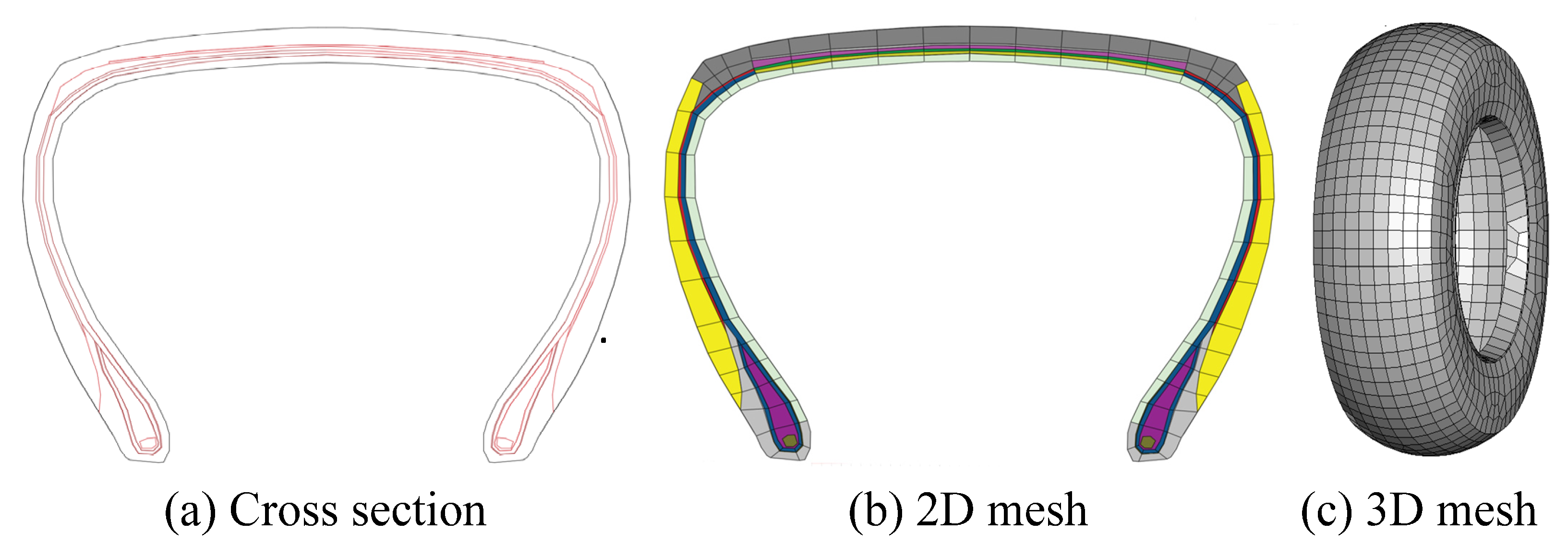
- Draw the tire’s cross-section, leaving out the tread, and then perform geometric cleaning. The tire’s cleaned cross-section is depicted in Figure 1a.
- Divide the FE mesh on the cross-sectional view of the tire in Figure 1a, as shown in Figure 1b in 2D. It is noted that the mesh size has a significant impact on the model’s computing time. A very small grid will increase the computation time and reduce the effectiveness of the computer. Therefore, we must choose a suitable mesh to shorten the computation times and improve the computing efficiency in order to ensure the model’s accuracy.
- On the two-dimensional mesh, we obtain the complete three-dimensional FE mesh model of the smooth tire by rotating it 360° and stitching the corresponding nodes, as shown in Figure 1c.
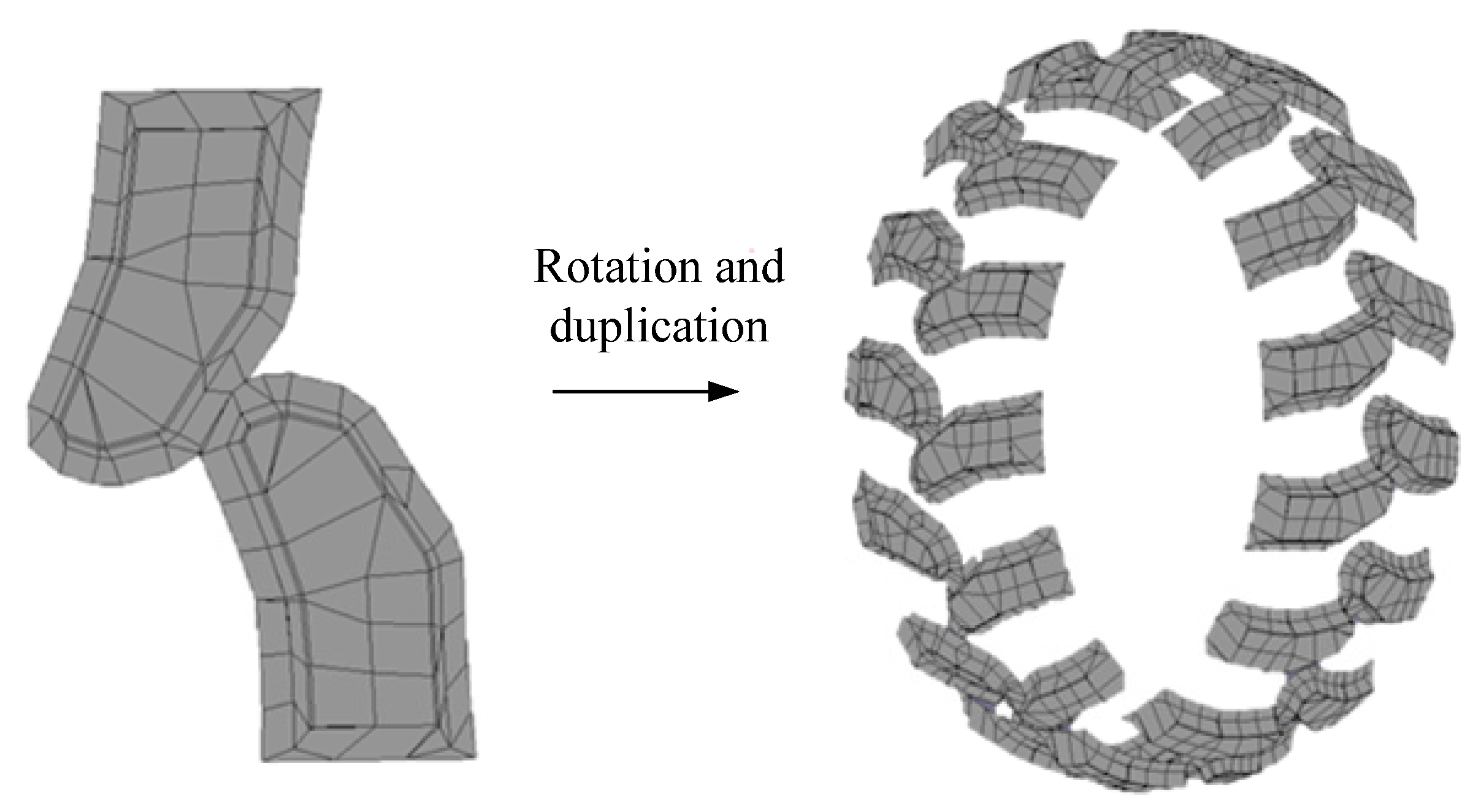
- Due to the periodicity of the pattern, we first establish a geometric model of the tread in a cycle, and then rotate the tread mesh for one revolution to obtain the final finite element mesh model of the tire tread using the rotation function. Figure 2 demonstrates the final FE model of the tire tread.
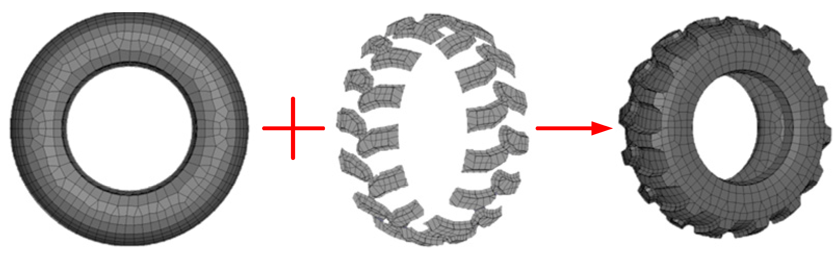
- Once the FE model of the tire body and tire tread are established, both the two components need to be adhered by means of a tied algorithm. Note that the nodes on the external surface of the tire body are set as the master surface, while the faces that match it on the tire tread are the slave surface, and the nodes on the slave surface are slave nodes, naturally. The resulting FE model of the tire is shown in Figure 3.
2.2. Model Parameters
2.3. Verification of Tire FE Model using Stiffness Experiments
3. Model of Snow-Covered Road
3.1. SPH Method
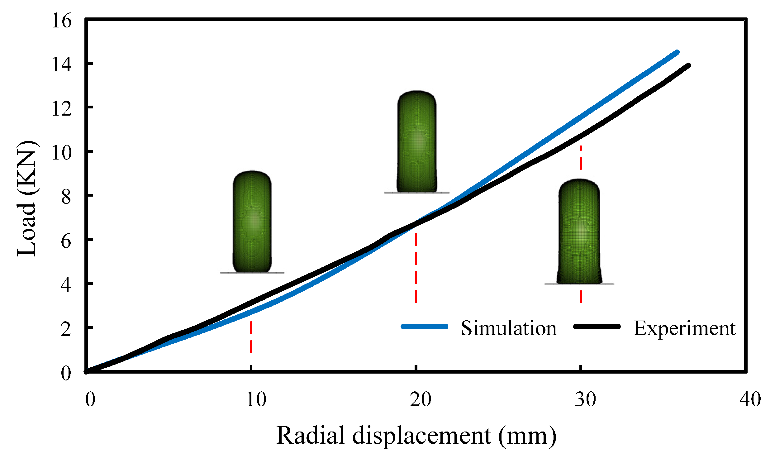
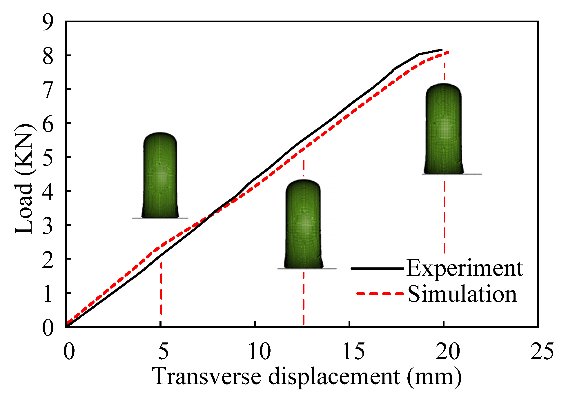
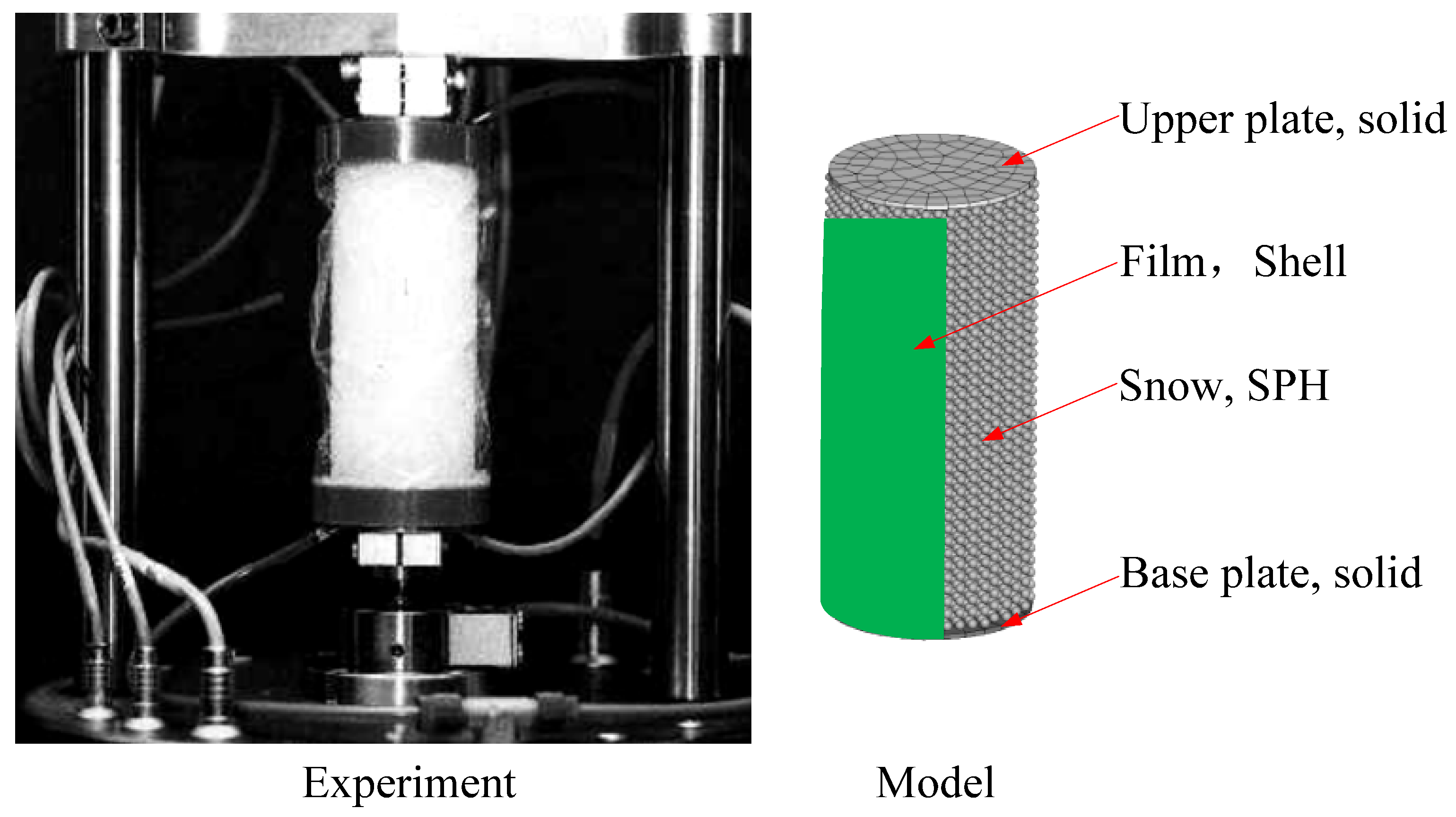
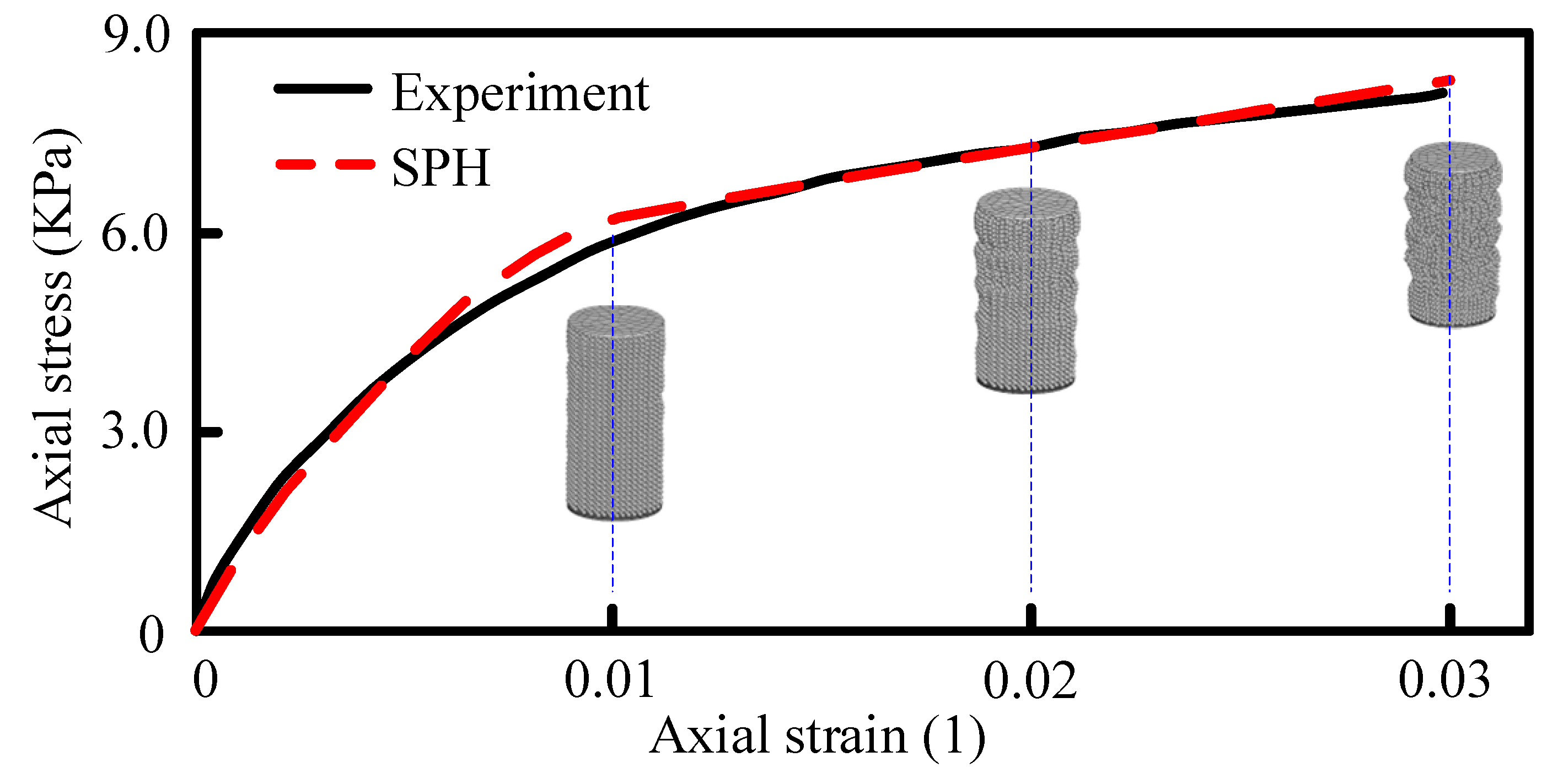
3.2. Parameter Calibration of SPH for Snow
4. Numerical Simulation of Tire Driving on Snow-Covered Road
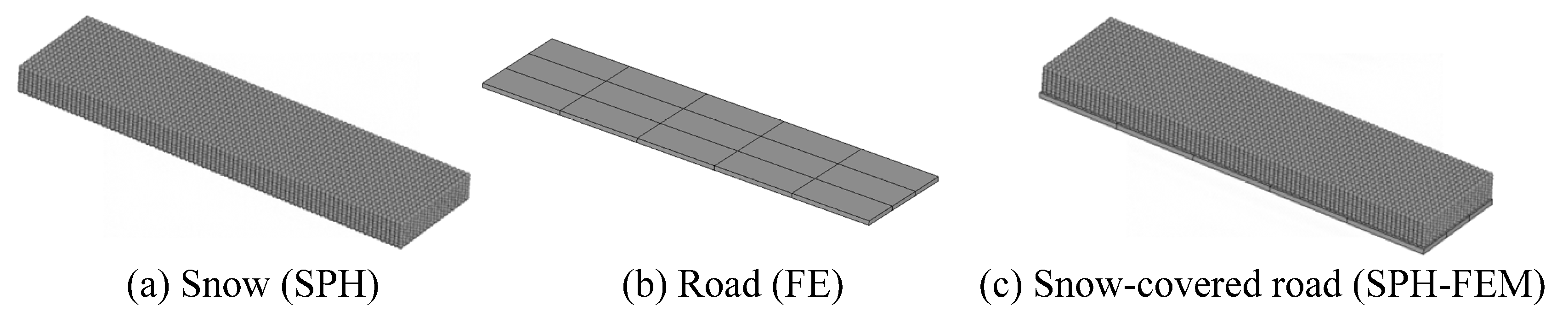
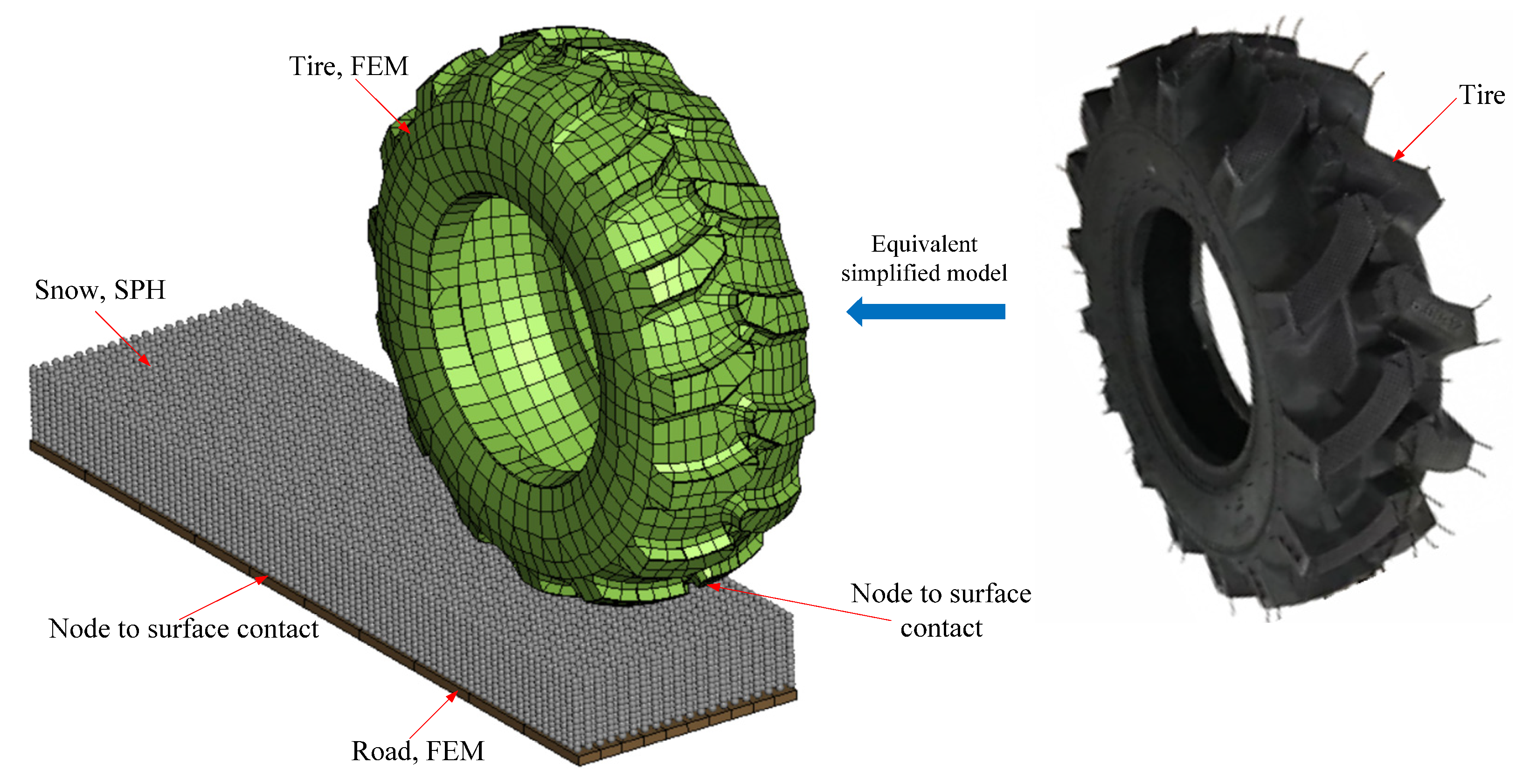
4.1. SPH-FEM Coupled Model
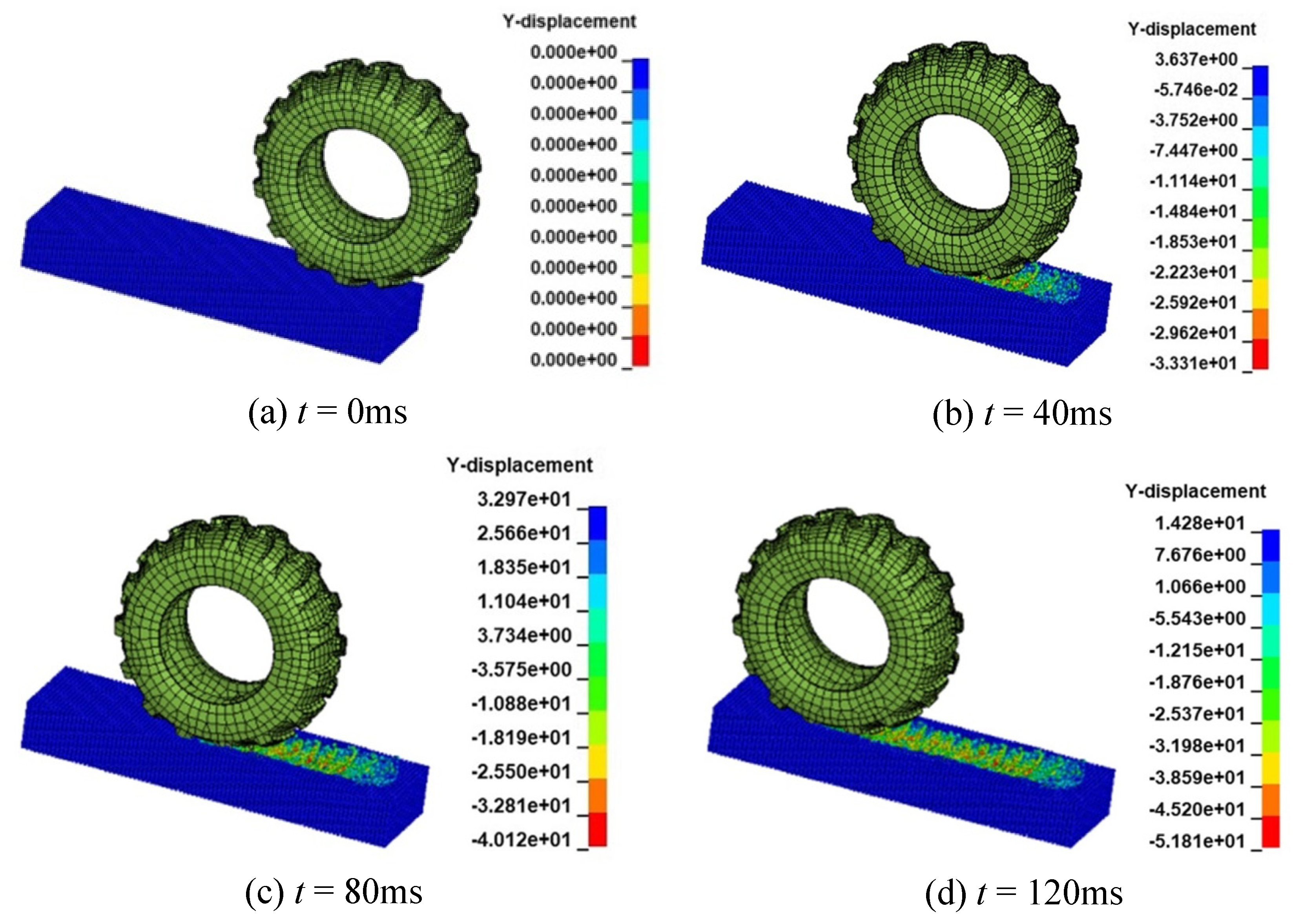
4.2. Numerical Simulation Examples
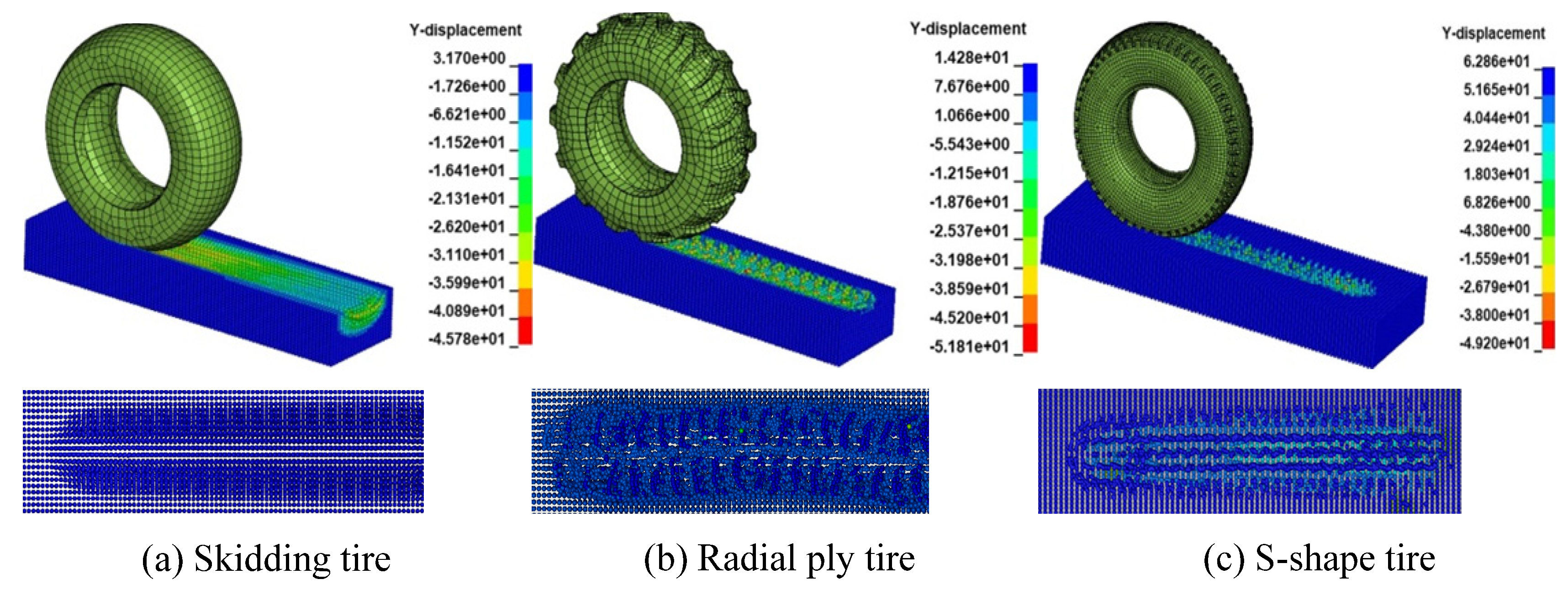
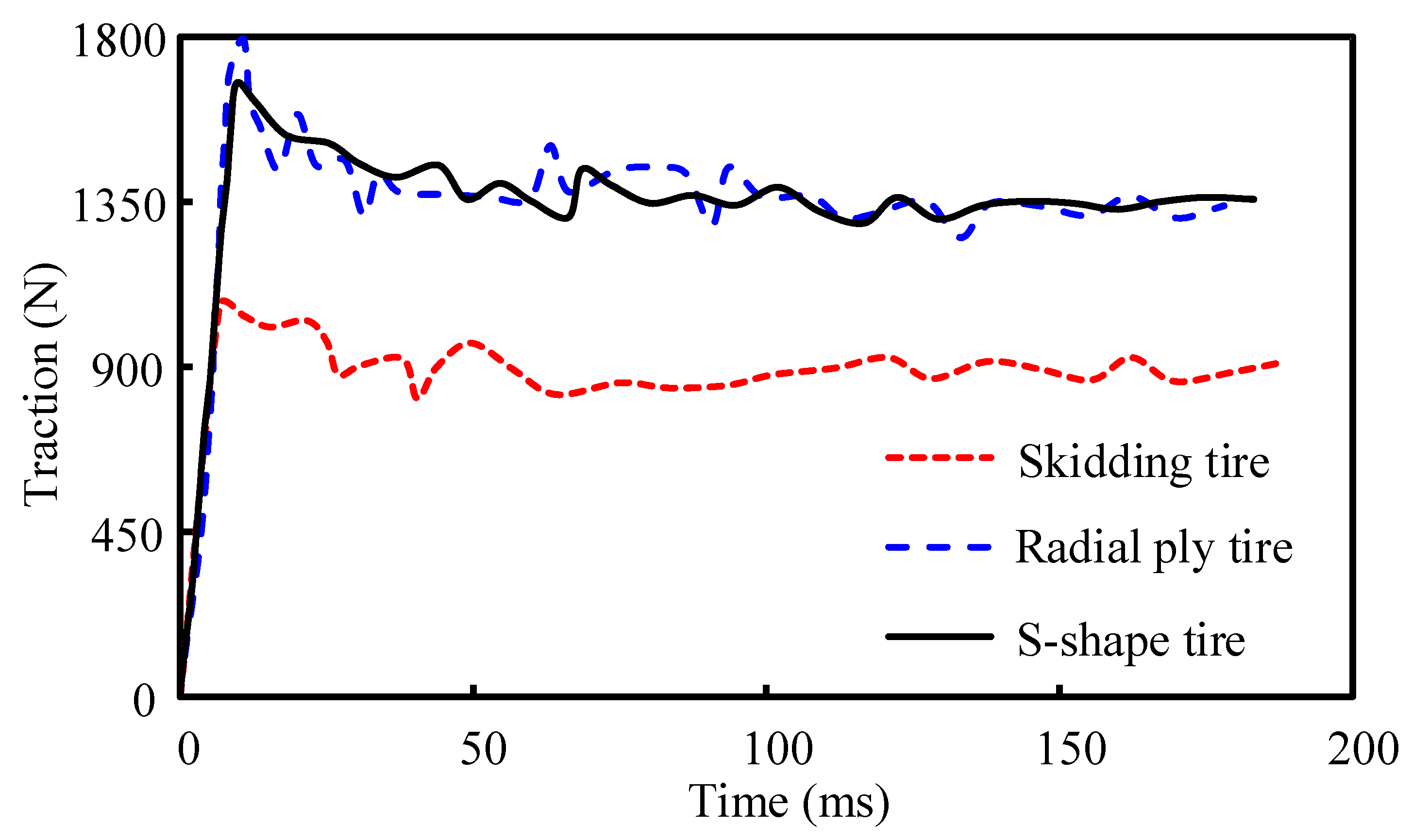
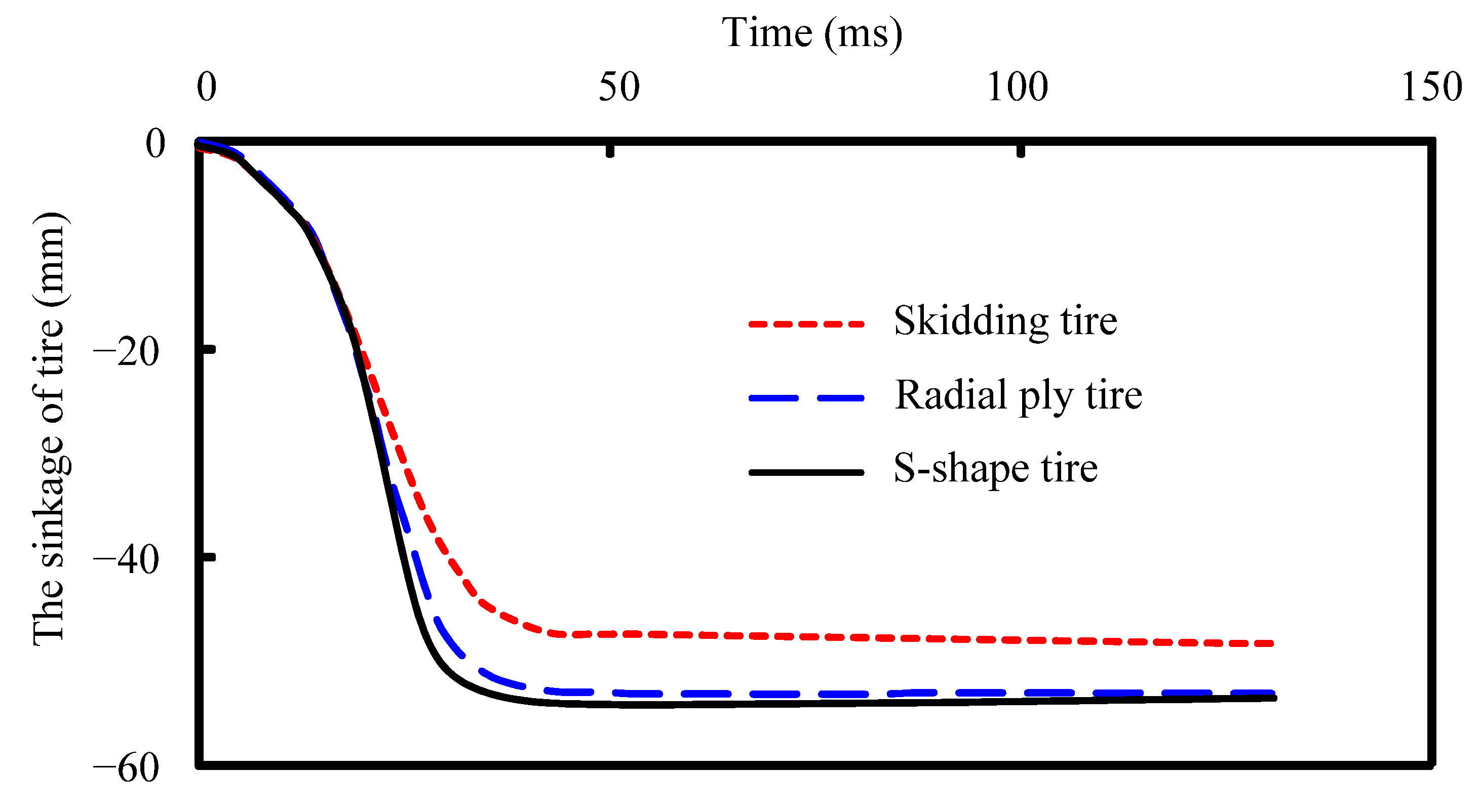
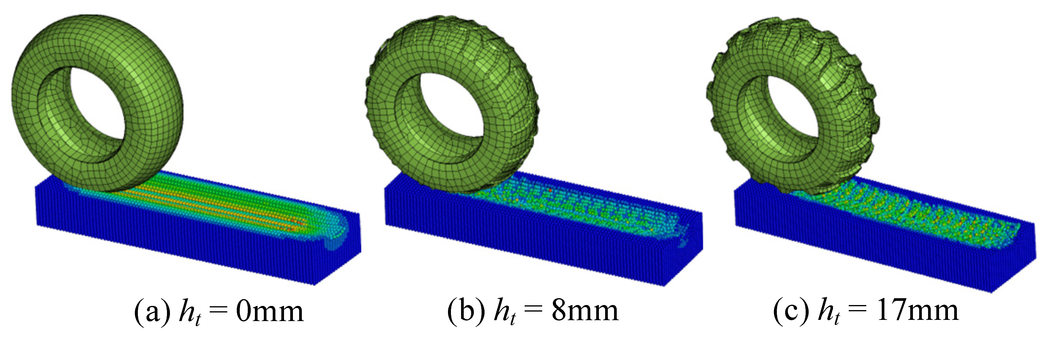
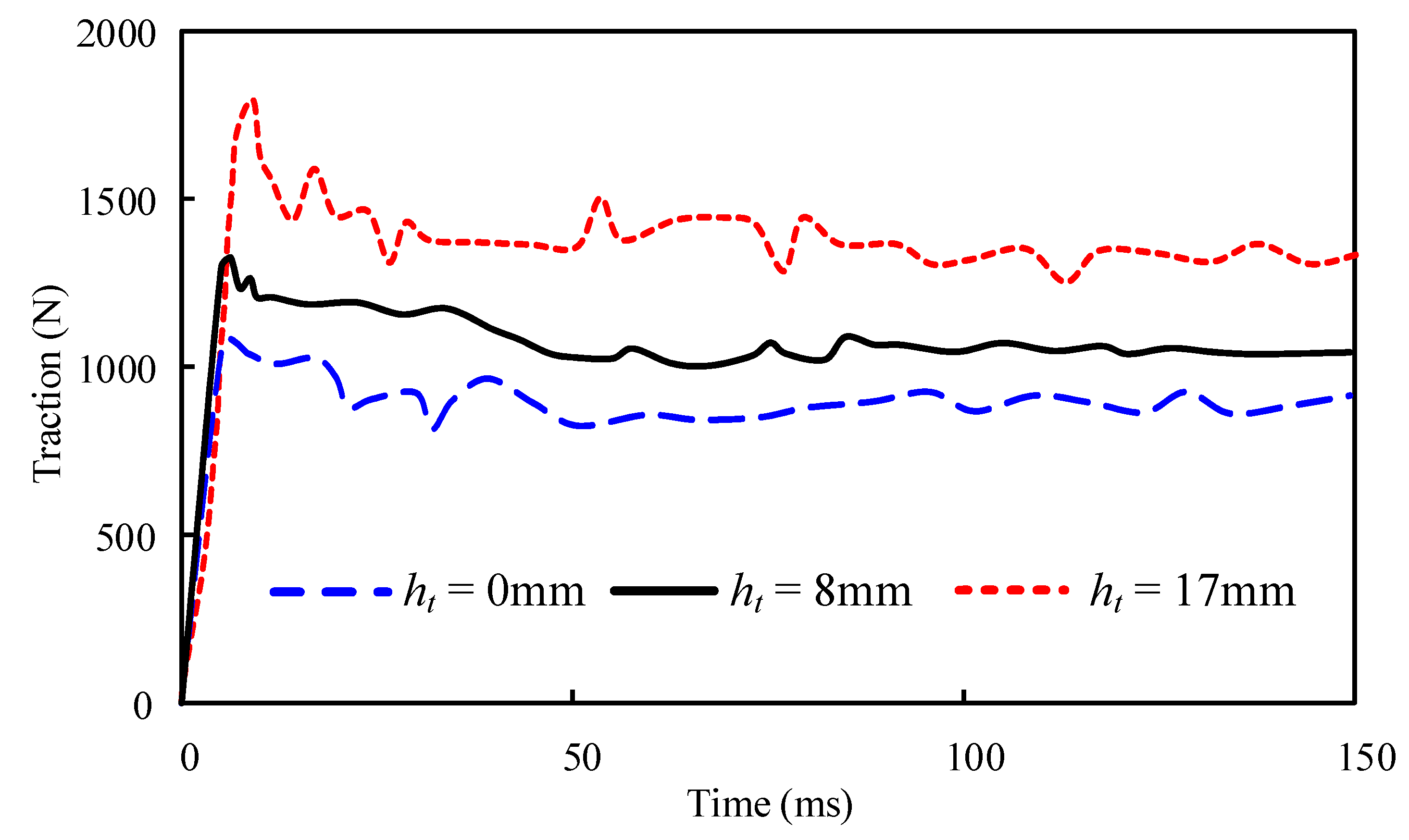
4.2.1. Tire Tread
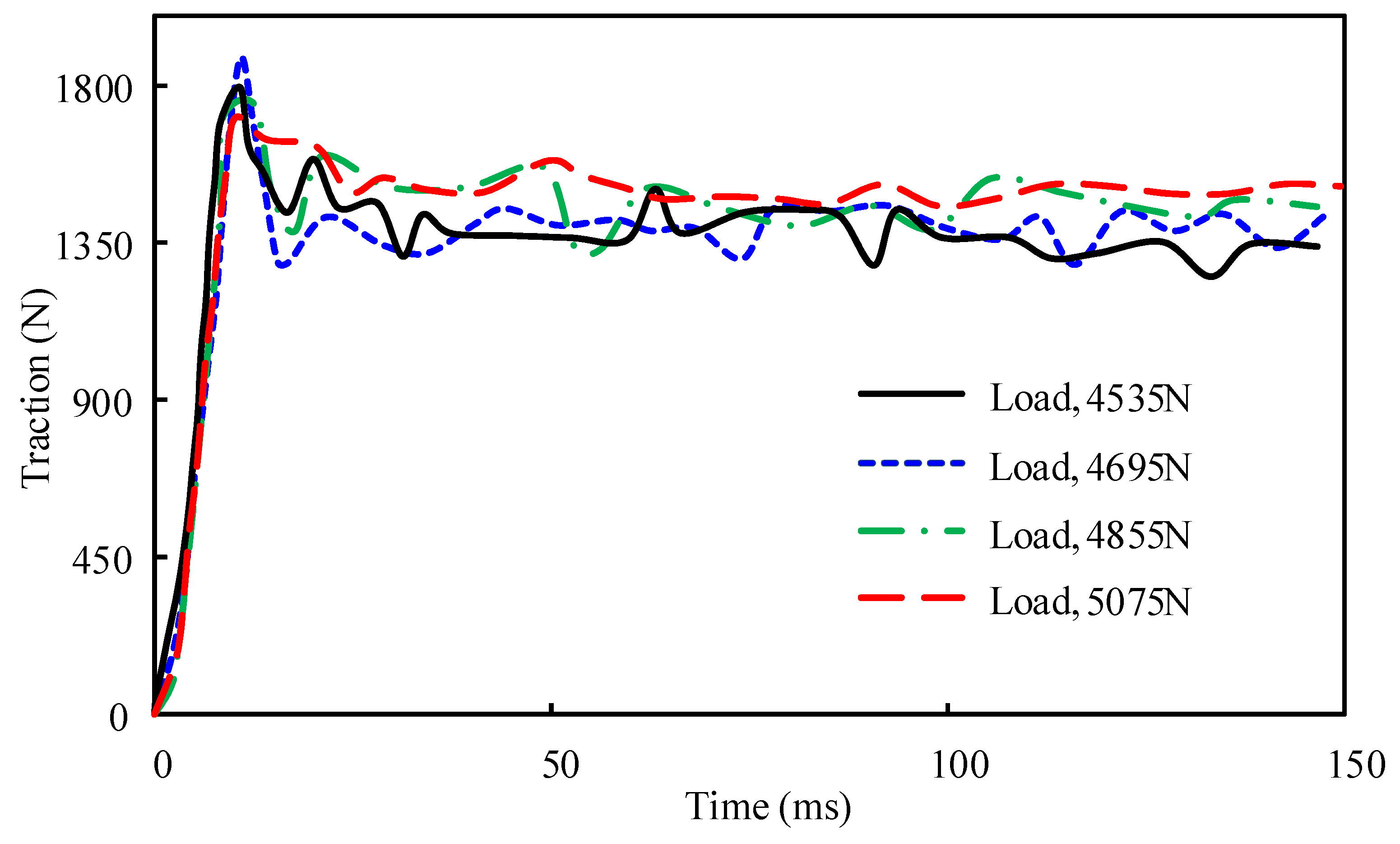
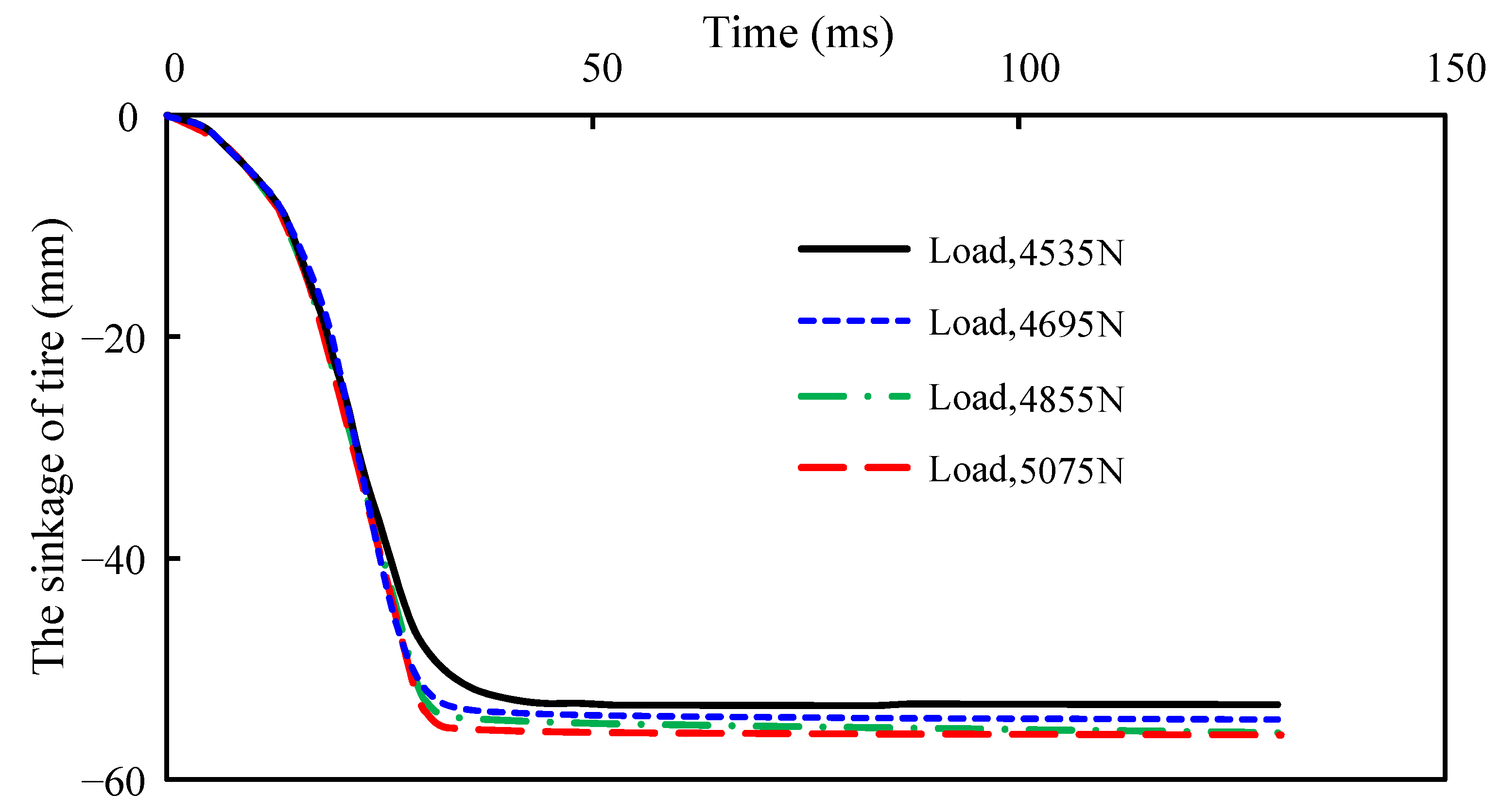
4.2.2. Wheel Load
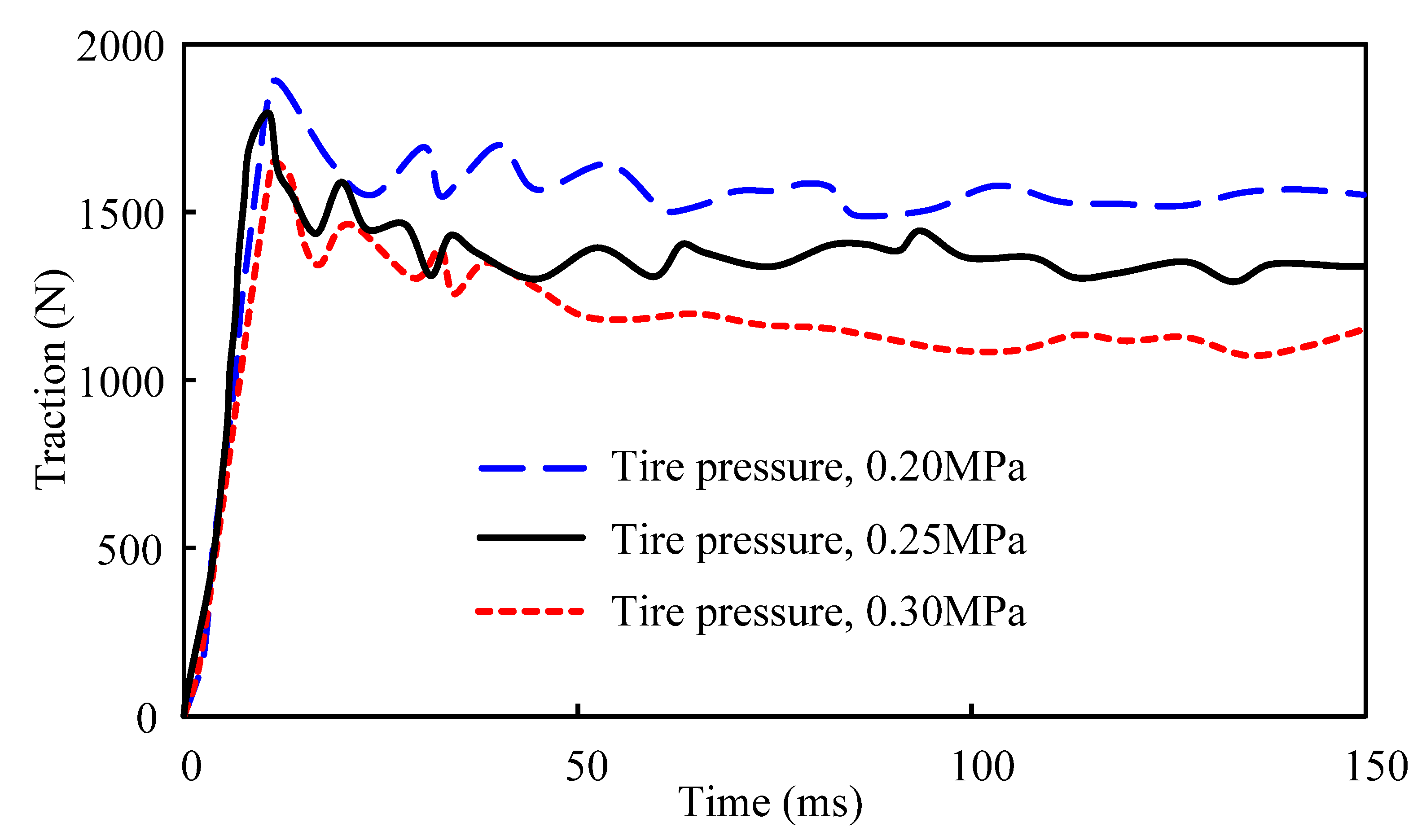
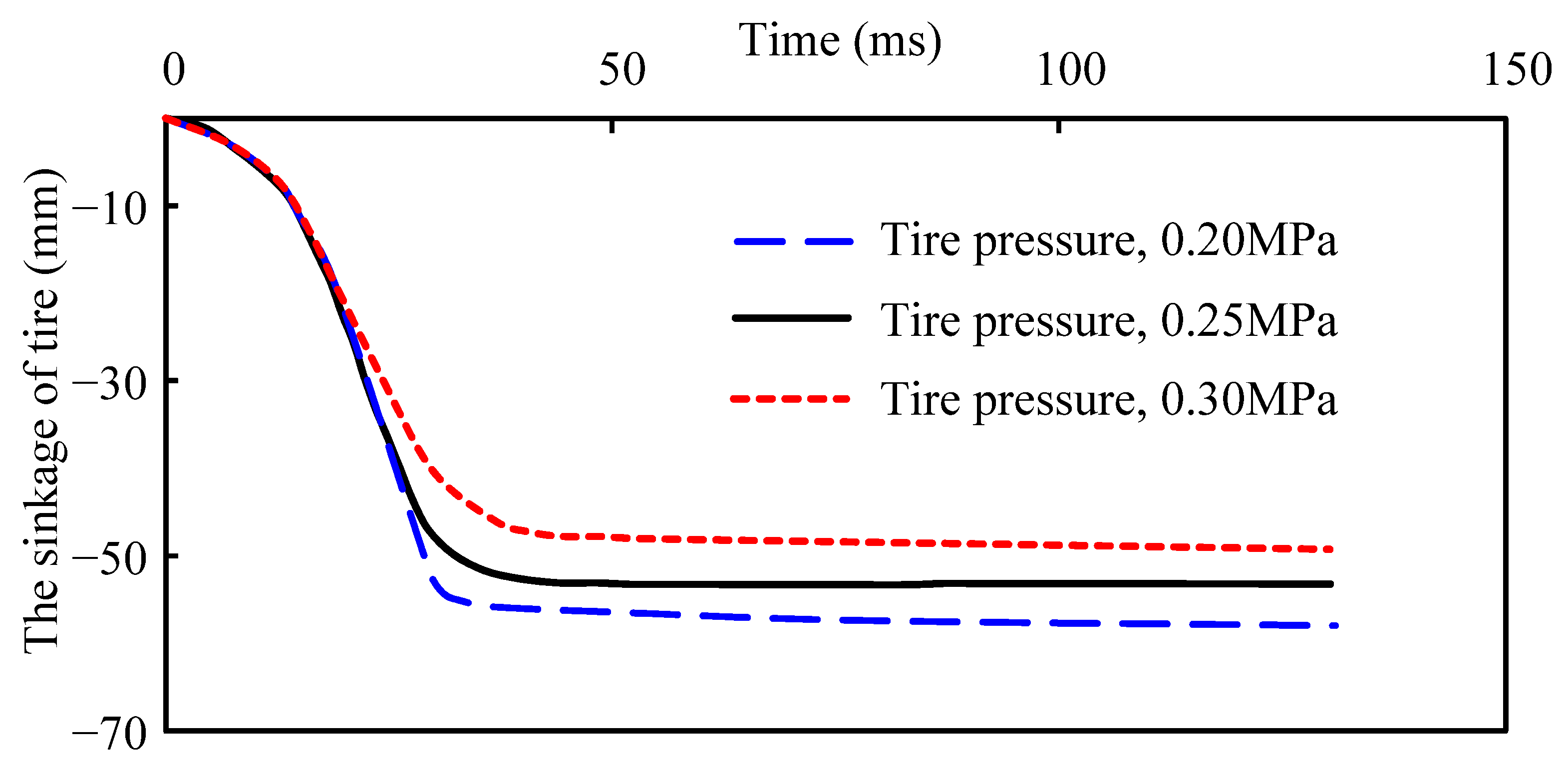
4.2.3. Tire Inflated Pressure
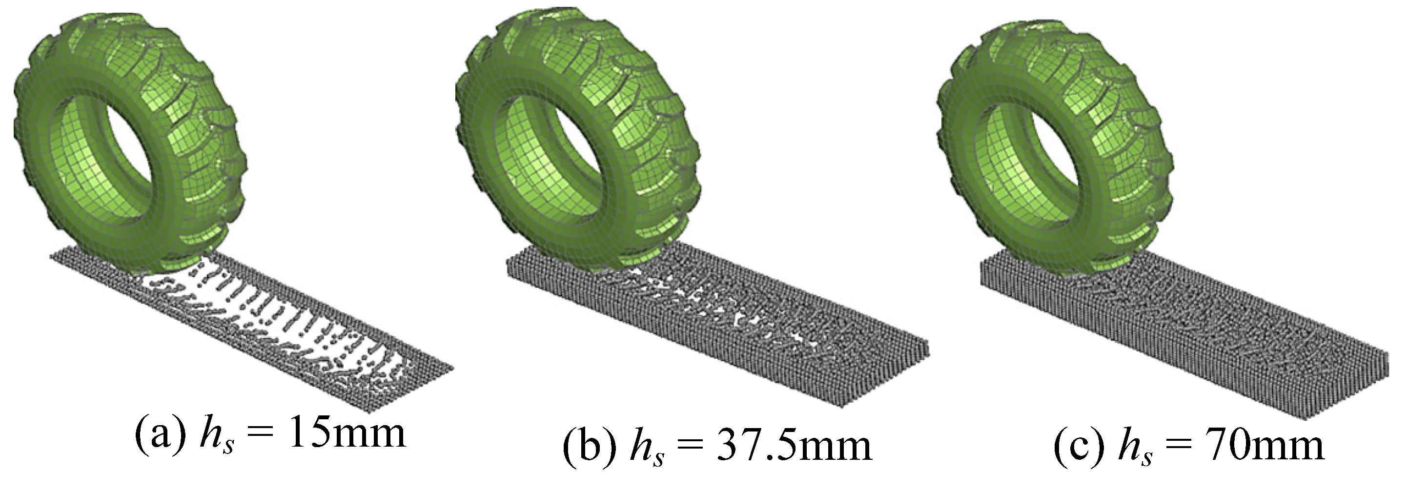
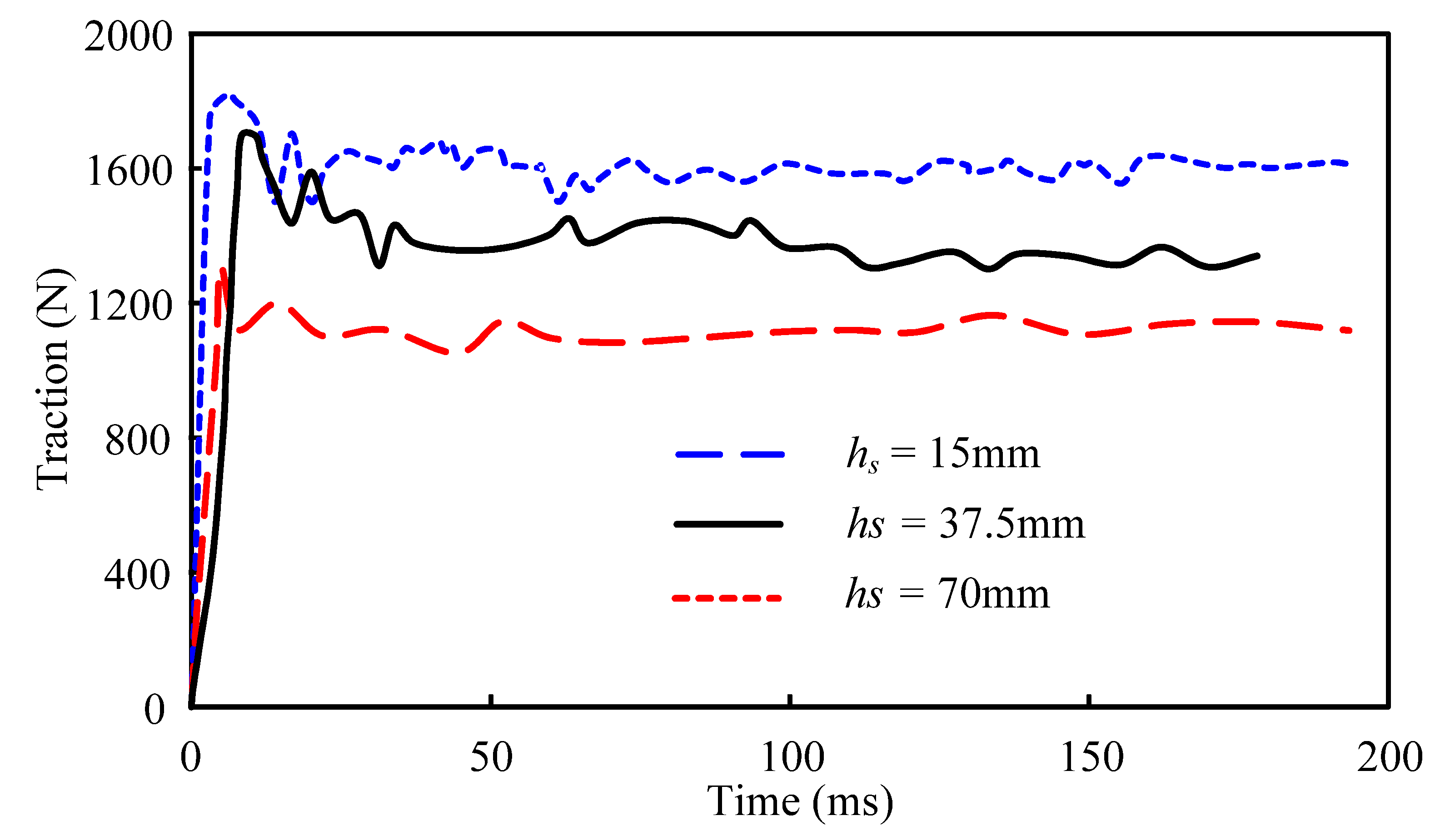
4.2.4. Snowfall
5. Conclusions
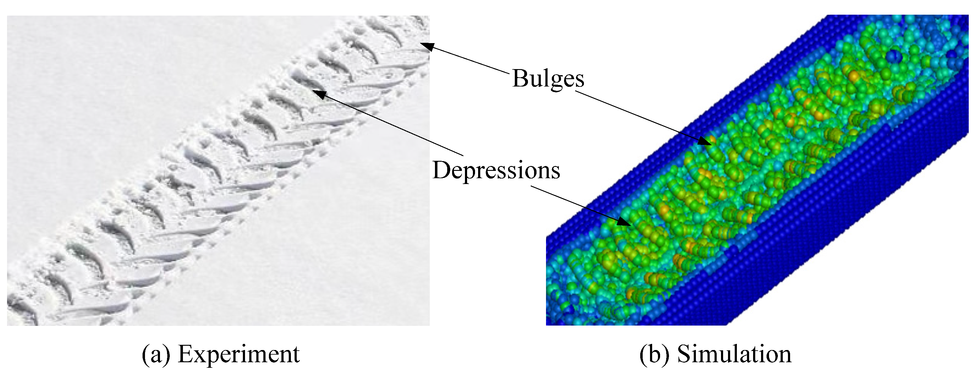
- The SPH model provides an accurate description of the fluidity, failure, and discontinuity of snow particles. The established FE model may also reflect the mechanical property of a tire.
- The tire treads model can obviously improve the operating capacity of the tire on the snow-covered road. The deeper the tread, the higher the performance of the tire.
- A positive correlation exists between the traction property and the wheel load. Therefore, a relatively high tire load can improve the tire’s coefficient of friction on the snowy ground, thus improving the tire’s performance on the snowy road.
- A lower inflated pressure will make it easier for the tire to attach to the snow, which will improve the traction of the tire while traveling. Therefore, it is suggested that the inflated pressure should be reduced correctly in order to increase the grip of the tires on the snow-covered road.
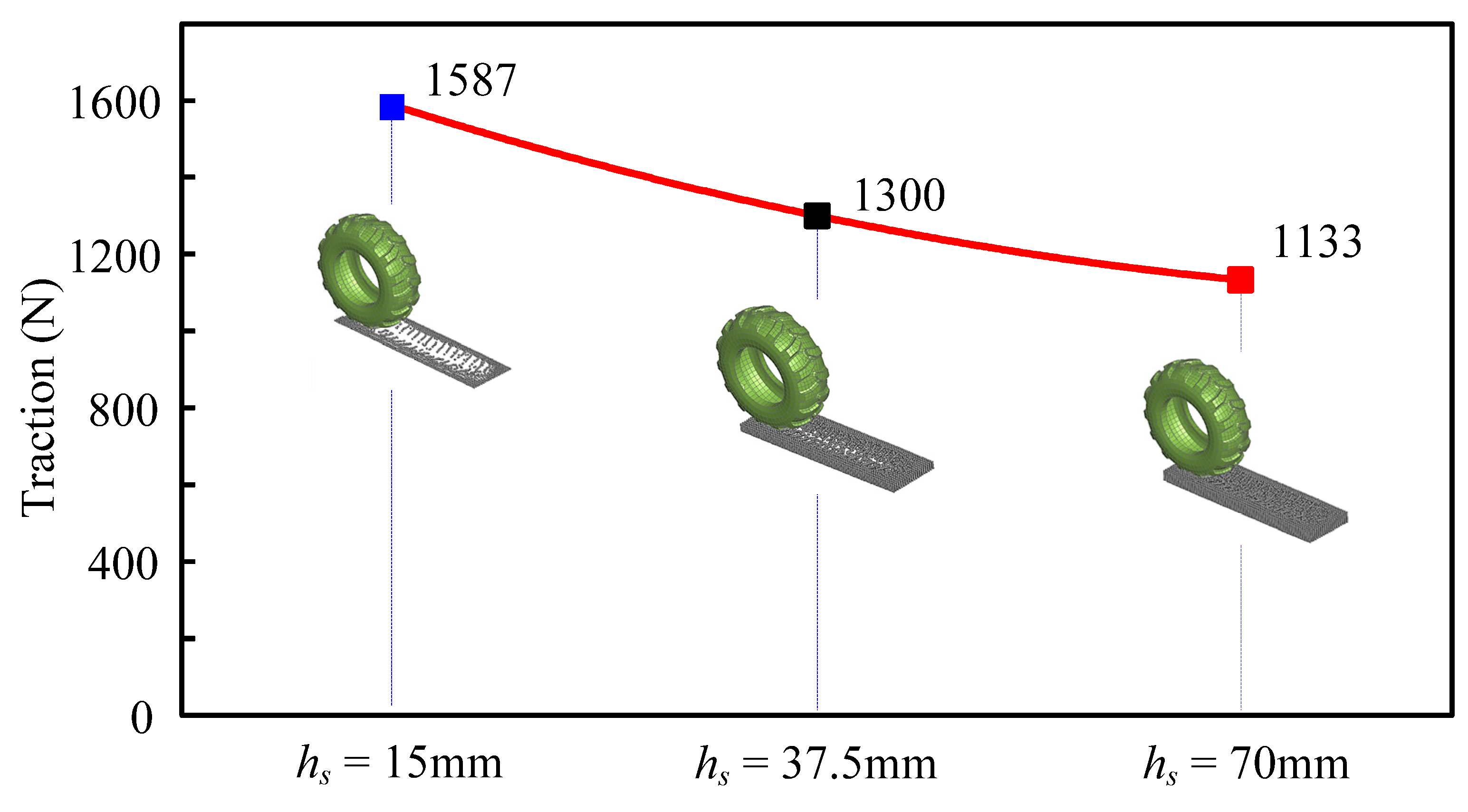
- Finally, the depth of snow on the road is a very important driver of road safety. Consequently, when applying anti-lock devices while driving on a snow-covered road, it is possible to effectively increase the coefficient of friction between the tire and the road surface, thereby reducing the risk of operation.
Author Contributions
Funding
Data Availability Statement
Conflicts of Interest
References
- Yanai, Y.; Hirota, T.; Iwata, Y.; Nemoto, M.; Koga, N.; Nagata, O.; Ohkubo, S. Snow cover manipulation in agricultural fields: As an option for mitigating greenhouse gas emissions. Ecol. Res. 2014, 29, 535–545. [Google Scholar] [CrossRef]
- Kazakov, Y.; Medvedev, V.; Batmanov, V.; Pavlov, V. Kinematics and dynamics of an incomplete circular wheel drive of an agricultural tractor. IOP Conf. Ser. Earth Environ. Sci. 2021, 935, 012030. [Google Scholar] [CrossRef]
- Zakirov, M.F. The research of resistance to snow cutting and moving with an auger of a small-sized rotary-auger snowplow. IOP Conf. Ser. Mater. Sci. Eng. 2020, 786, 012043. [Google Scholar] [CrossRef]
- Pomerleau, F. Robotics in snow and ice. arXiv 2022, arXiv:2208.05095. [Google Scholar]
- Mills, B.; Andrey, J.; Doherty, S.; Doberstein, B.; Yessis, J. Winter storms and fall-related injuries: Is it safer to walk than to drive. Weather. Clim. Soc. 2020, 12, 421–434. [Google Scholar] [CrossRef] [Green Version]
- Mills, B.; Andrey, J.; Doberstein, B.; Doherty, S.; Yessis, J. Changing patterns of motor vehicle collision risk during winter storms: A new look at a pervasive problem. Accid. Anal. Prev. 2019, 127, 186–197. [Google Scholar] [CrossRef]
- Linke, T.; Wiese, K.; Wangenheim, M.; Wies, B.; Wallashek, J. Investigation of snow milling mechanics to optimize winter tire traction. Tire Sci. Technol. 2017, 45, 162–174. [Google Scholar] [CrossRef]
- Riehm, P.; Unrau, H.J.; Gauterin, F.; Torbrügge, S.; Wies, B. 3D brush model to predict longitudinal tyre characteristics. Veh. Syst. Dyn. 2019, 57, 17–43. [Google Scholar] [CrossRef]
- Rao, S.S. The Finite Element Method in Engineering; Butterworth-Heinemann: Oxford, UK, 2017. [Google Scholar]
- Surkutwar, Y.; Sandu, C.; Untaroiu, C. Review of modeling methods of compressed snow-tire interaction. J. Terramechanics 2023, 105, 27–40. [Google Scholar] [CrossRef]
- Darwish, M.; Moukalled, F. The Finite Volume Method in Computational Fluid Dynamics: An Advanced Introduction with OpenFOAM® and Matlab®; Springer: Berlin/Heidelberg, Germany, 2016. [Google Scholar]
- Seta, E.; Nakai, T.; Heggli, M.; Jaggi, M.; Löwe, H.; Schneebeli, M.; Szabo, D. Prediction of tire traction on a compacted snow road. In Physics and Chemistry of Ice 2010; Hokkaido University Press: Sapporo, Japan, 2010; pp. 45–49. [Google Scholar]
- Choi, J.H.; Cho, J.R.; Woo, J.S.; Kim, K. Numerical investigation of snow traction characteristics of 3-D patterned tire. J. Terramechanics 2012, 49, 81–93. [Google Scholar] [CrossRef]
- Lee, J.H. Calibration and validation of a tire–snow interaction model. J. Terramechanics 2013, 50, 289–302. [Google Scholar] [CrossRef]
- Theile, T.; Szabo, D.; Willibald, C.; Schneebeli, M. Discrete element model for high strain rate deformations of snow. arXiv 2020, arXiv:2007.01694. [Google Scholar]
- Kabore, B.W.; Peters, B.; Michael, M.; Nicot, F. A discrete element framework for modeling the mechanical behaviour of snow Part I: Mechanical behaviour and numerical model. Granul. Matter 2021, 23, 42. [Google Scholar] [CrossRef]
- Peters, B.; Kabore, B.W.; Michael, M.; Nicot, F. A discrete element framework for modeling the mechanical behaviour of snow Part II: Model validation. Granul. Matter 2021, 23, 43. [Google Scholar] [CrossRef]
- Goswami, P.; Nordin, A.; Nylén, S. Iterative discrete element solver for efficient snow simulation. In Proceedings of the Eurographics Symposium on Parallel Graphics and Visualization (EGPGV), Rome, Italy, 13 June 2022. [Google Scholar]
- Bui, H.H.; Nguyen, G.D. Smoothed particle hydrodynamics (SPH) and its applications in geomechanics: From solid fracture to granular behaviour and multiphase flows in porous media. Comput. Geotech. 2021, 138, 104315. [Google Scholar] [CrossRef]
- Gheshlaghi, F.; El-Sayegh, Z.; El-Gindy, M.; Oijer, F.; Johansson, I. Advanced Analytical Truck Tires-Terrain Interaction Model; SAE Technical Paper; SAE International: Warrendale, PA, USA, 2021. [Google Scholar]
- Gheshlaghi, F.; Mardani, A.; Mohebbi, A. Investigating the effects of off-road vehicles on soil compaction using FEA-SPH simulation. Int. J. Heavy Veh. Syst. 2021, 28, 455–466. [Google Scholar] [CrossRef]
- Ly, A.; El-Sayegh, Z.; El-Gindy, M.; Oijer, F.; Johansson, I. A Comprehensive Study of the Impact of Tread Design on the Tire-Terrain Interaction using Advanced Computational Techniques; SAE Technical Paper; SAE International: Warrendale, PA, USA, 2023. [Google Scholar]
- Saadat, M.; Taheri, A. A cohesive discrete element based approach to characterizing the shear behavior of cohesive soil and clay-infilled rock joints. Comput. Geotech. 2019, 114, 103109. [Google Scholar] [CrossRef]
- Pan, C.; Li, X.; He, L.; Li, J. Study on the effect of micro-geometric heterogeneity on mechanical properties of brittle rock using a grain-based discrete element method coupling with the cohesive zone model. Int. J. Rock Mech. Min. Sci. 2021, 140, 104680. [Google Scholar] [CrossRef]
- De Biagi, V.; Barbero, M.; Barpi, F.; Borri-Brunetto, M.; Podolskiy, E. Failure mechanics of snow layers through image analysis. Eur. J. Mech. A/Solids 2019, 74, 26–33. [Google Scholar] [CrossRef]
- Gaume, J.; Chambon, G.; Eckert, N.; Naaim, M.; Schweizer, J. Influence of weak layer heterogeneity and slab properties on slab tensile failure propensity and avalanche release area. Cryosphere 2015, 9, 795–804. [Google Scholar] [CrossRef] [Green Version]
- Steinkogler, W.; Gaume, J.; Lowe, H.; Sovilla, B.; Lehning, M. Granulation of snow: From tumbler experiments to discrete element simulations. J. Geophys. Res. Earth Surf. 2015, 120, 1107–1126. [Google Scholar] [CrossRef] [Green Version]
- Mulak, D.; Gaume, J. Numerical investigation of the mixed-mode failure of snow. Comput. Part. Mech. 2019, 6, 439–447. [Google Scholar] [CrossRef] [Green Version]
- Michael, M. A Discrete Approach to Describe the Kinematics between Snow and a Tire Tread. Ph.D. Thesis, University of Luxembourg, Luxembourg, 2014. [Google Scholar]
- Gissler, C.; Henne, A.; Band, S.; Peer, A.; Teschner, M. An implicit compressible SPH solver for snow simulation. ACM Trans. Graph. TOG 2020, 39, 1–16. [Google Scholar] [CrossRef]
- El-Sayegh, Z.; El-Gindy, M. Modelling and prediction of tyre–snow interaction using finite element analysis–smoothed particle hydrodynamics techniques. Proc. Inst. Mech. Eng. Part D J. Automob. Eng. 2019, 233, 1783–1792. [Google Scholar] [CrossRef]
- Goswami, P.; Markowicz, C.; Hassan, A. Real-time particle-based snow simulation on the GPU. In Proceedings of the Eurographics—European Association for Computer Graphics (EGPGV), Genoa, Italy, 6–10 May 2019. [Google Scholar]
- Chunnoo, M. Simulating Snow as an Elastoplastic Material on the GPU. Master’s Thesis, NTNU, Torgarden, Norway, 2022. [Google Scholar]
- Zeng, H.; Xu, W.; Zang, M.; Yang, P. Experimental and numerical investigations of tractive performance of off-road tires on gravel terrain. Int. J. Comput. Methods 2020, 17, 1950055. [Google Scholar] [CrossRef]
- Qiu, G.; Henke, S.; Grabe, J. Application of a coupled Eulerian-Lagrangian approach on geomechanically problems involving large deformations. Comput. Geotech. 2011, 38, 30–39. [Google Scholar] [CrossRef]
- Fragassa, C.; Marinkovic, D.; Vitković, N.; Trajanović, M. Performance evaluation of cord material models applied to structural analysis of tires. Compos. Struct. 2019, 224, 111006. [Google Scholar]
- Xu, W.; Zeng, H.; Yang, P.; Zang, M. Numerical analysis on tractive performance of off-road tire on gravel road using a calibrated finite element method–discrete element method model and experimental validation. Proc. Inst. Mech. Eng. Part D J. Automob. Eng. 2020, 234, 3440–3457. [Google Scholar] [CrossRef]
- Weipan, X.U.; Haiyang, Z.; Chao, J.; Xizheng, K.O.U.; Mengyan, Z.A.N.G. Simulation of tractive performance of off-road tire on gravel road by combined finite element-discrete ElementMethod and experimental validation. Acta Armamentarii 2019, 40, 1961. [Google Scholar]
- Zang, M.Y.; Xu, Y.W.; Zhou, T. Characteristics simulation of five kinds of stiffness of tire based on three-dimension nonlinear model. J. South China Univ. Technol. 2011, 39, 129–133. [Google Scholar]
- El-Sayegh, Z.; El-Gindy, M.; Johansson, I.; Öijer, F. Improved tire-soil interaction model using FEA-SPH simulation. J. Terramechanics 2018, 78, 53–62. [Google Scholar] [CrossRef]
- Bui, H.H.; Fukagawa, R.; Sako, K.; Ohno, S. Lagrangian meshfree particles method (SPH) for large deformation failure flows of geomaterial using elastic–plastic soil constitutive model. Int. J. Methods Geomech. 2008, 32, 1537–1570. [Google Scholar] [CrossRef]
- Von Moos, M.; Bartelt, P.; Zweidler, A. Triaxial tests on snow at low strain rate. Part I. Experimental device. Glaciers Frozen Soil 2003, 49, 81–90. [Google Scholar]
- Bogdevičius, M.; Ružinskas, A.; Vadlūga, V.; Bogdevičius, P.; Kačianauskas, R.; Maknickas, A.; Gauterin, F. Investigation of tire force transmission on interaction with slush. Transp. Probl. 2019, 14, 13–21. [Google Scholar] [CrossRef] [Green Version]
- Shoop, S.; Young, B.; Alger, R.; Davis, J. Effect of test method on winter traction measurements. J. Terramechanics 1994, 31, 153–161. [Google Scholar] [CrossRef]
- Caban, J.; Turski, A.; Nieoczym, A.; Tarkowski, S.; Jereb, B. Impact of specific factors on the state of the tire pressurevalue. Archiwum Motoryzacji 2019, 85, 137–148. [Google Scholar] [CrossRef]


| Method | Merits | Demerits | |
|---|---|---|---|
| Mesh-based | Lagrange | This method is mature and computationally efficient [34]. | The shortcoming of this method is that it cannot be used to describe the large deformation problem, and breaking frequently happens during the computation [10]. |
| Euler | This approach can be used to model large deformation problems [35]. | This method is computationally inefficient [10]. | |
| Particle-based | DEM | This method can be used to simulate the mechanical properties of discrete snow and to describe the spray phenomenon [34]. | This method is computationally inefficient [34]. |
| SPH | The SPH method has the advantage of computational accuracy in describing the liquidity and large deformation of snow [10]. | ||
| Rubber Material Component | Density, kg∙m3 | Yeoh Strain Energy Potential Constants | |||
|---|---|---|---|---|---|
| C10 | C20 | C30 | Di (i = 1,2,3) | ||
| Tread rubber | 1.13 × 10³ | 2.37 | −9.87 | 43.66 | 0 |
| Belt rubber | 7.53 × 10³ | 5.65 | −35.12 | 145.76 | 0 |
| Carcass rubber | 3.85 × 10³ | 3.67 | −14.73 | 77.87 | 0 |
| Inner liner rubber | 1.14 × 10³ | 2.13 | −14.91 | 67.67 | 0 |
| Sidewall rubber | 1.08 × 10³ | 2.26 | −10.00 | 45.30 | 0 |
| Apex rubber | 1.15 × 10³ | 2.15 | −7.84 | 33.91 | 0 |
| Bead filler rubber | 1.17 × 10³ | 4.76 | −12.97 | 65.78 | 0 |
| Bead rubber | 1.23 × 10³ | 4.55 | −39.05 | 179.76 | 0 |
| Parameter, Unit | Belt Layer | Cord Ply Layer | Bead |
|---|---|---|---|
| Density, kg∙m−3 | 4.99 × 10³ | 1.14 × 10³ | 7.80 × 10³ |
| Young’s modulus, MPa | |||
| Ea | 80,641.06 | 22,002.34 | 149,403.06 |
| Eb | 57.49 | 24.27 | 281.65 |
| Ec | 57.49 | 24.27 | 281.65 |
| Poisson’s ratio | |||
| Vba | 2.67 × 10⁻⁴ | 4.49 × 10⁻⁴ | 6.26 × 10⁻⁴ |
| Vca | 2.67 × 10⁻⁴ | 4.49 × 10⁻⁴ | 6.26 × 10⁻⁴ |
| Vcb | 0.49 | 0.49 | 0.49 |
| Shear modulus, MPa | |||
| Gab | 13.99 | 6.01 | 64.96 |
| Gbc | 19.29 | 8.14 | 94.51 |
| Gca | 13.99 | 6.01 | 64.96 |
| Part | Rigid Plate | PVC |
|---|---|---|
| Density, g∙mm−3 | 7.85 × 10⁻³ | 1.17 × 10⁻³ |
| Young’s modulus, Pa | 2.1 × 10¹¹ | |
| Poisson’s ratio | 0.30 | 0.49 |
| Parameter | Value |
|---|---|
| Static friction coefficient (SPH–Road) | 0.60 |
| Kinetic friction coefficient (SPH–Road) | 0.40 |
| Static friction coefficient (SPH–Tire) | 0.30 |
| Kinetic friction coefficient (SPH–Tire) | 0.15 |
| Smoothing length | 1.20 |
| Scaling factor for smoothing length | 0.20 |
Disclaimer/Publisher’s Note: The statements, opinions and data contained in all publications are solely those of the individual author(s) and contributor(s) and not of MDPI and/or the editor(s). MDPI and/or the editor(s) disclaim responsibility for any injury to people or property resulting from any ideas, methods, instructions or products referred to in the content. |
© 2023 by the authors. Licensee MDPI, Basel, Switzerland. This article is an open access article distributed under the terms and conditions of the Creative Commons Attribution (CC BY) license (https://creativecommons.org/licenses/by/4.0/).
Share and Cite
Wang, D.; Wang, H.; Xu, Y.; Zhou, J.; Sui, X. Numerical Simulations of the Driving Process of a Wheeled Machine Tire on a Snow-Covered Road. Machines 2023, 11, 657. https://doi.org/10.3390/machines11060657
Wang D, Wang H, Xu Y, Zhou J, Sui X. Numerical Simulations of the Driving Process of a Wheeled Machine Tire on a Snow-Covered Road. Machines. 2023; 11(6):657. https://doi.org/10.3390/machines11060657
Chicago/Turabian StyleWang, Di, Hui Wang, Yan Xu, Jianpin Zhou, and Xinyu Sui. 2023. "Numerical Simulations of the Driving Process of a Wheeled Machine Tire on a Snow-Covered Road" Machines 11, no. 6: 657. https://doi.org/10.3390/machines11060657