Review

Overview of Multi-Robot Collaborative SLAM from the Perspective of Data Fusion

1
College of Mechanical and Electronic Engineering, Quanzhou University of Information Engineering, Quanzhou 362000, China
2
School of Automation, Nanjing University of Information Science and Technology, Nanjing 210044, China
3
Jiangsu Collaborative Innovation Center of Atmospheric Environment and Equipment Technology (CICAEET), Nanjing University of Information Science and Technology, Nanjing 210044, China
*
Author to whom correspondence should be addressed.
Machines 2023, 11(6), 653; https://doi.org/10.3390/machines11060653
Submission received: 23 May 2023 / Revised: 9 June 2023 / Accepted: 15 June 2023 / Published: 17 June 2023
(This article belongs to the Section Automation and Control Systems)

Abstract

:
In the face of large-scale environmental mapping requirements, through the use of lightweight and inexpensive robot groups to perceive the environment, the multi-robot cooperative (V)SLAM scheme can resolve the individual cost, global error accumulation, computational load, and risk concentration problems faced by single-robot SLAM schemes. Such schemes are robust and stable, form a current research hotspot, and relevant algorithms are being updated rapidly. In order to enable the reader to understand the development of this field rapidly and fully, this paper provides a comprehensive review. First, the development history of multi-robot collaborative SLAM is reviewed. Second, the fusion algorithms and architectures are detailed. Third, from the perspective of machine learning classification, the existing algorithms in this field are discussed, including the latest updates. All of this will make it easier for readers to discover problems that need to be studied further. Finally, future research prospects are listed.

1. Introduction

With the continuous development of mobile robot technology, robots have come to be applied in many fields. Countries around the world are constantly developing robotics technology to realize the application of robots in more diverse scenarios, including rescue robots for disaster rescue, exploration robots for harsh environments (e.g., deep sea exploration), and unmanned vehicles for planetary exploration and self-driving cars. The wide application range of these robots also raises a key issue: the robots need to carry high-precision simultaneous localization and mapping technology. Without this technology, rescue robots cannot find injured people in unknown environments promptly, exploration robots cannot effectively explore unknown environments, unmanned vehicles for planetary exploration cannot locate themselves, deep-sea exploration robots cannot build a complete map of the seafloor, and autonomous vehicles may deviate from the track while driving, creating serious safety hazards. SLAM technology can help mobile robots to locate their position and construct maps of the surrounding environment effectively; as such, it has become a key technology for solving these problems.
SLAM is short for simultaneous localization and mapping. SLAM technology originated in the field of robotics, proposed by Smith et al. [1] in 1986 at the IEEE Conference on Robotics and Automation. The SLAM problem can be formulated in terms of putting a robot in an unknown position in an unknown environment, and determining whether there exists a way for the robot to gradually describe the map of the environment while moving and estimating its motion.
In this paper, SLAM is classified according to the types of sensors used by robots, such as camera, LiDAR, and sonar. SLAM methods using these sensors are called VSLAM (visual simultaneous localization and mapping), laser SLAM, and sonar SLAM, respectively. Of these, VSLAM is the closest to the way in which humans perceive their environment. In the early days of SLAM, researchers focused more on other sensors, such as LiDAR, sonar, and IMUs. In recent years, with the continuous development of SLAM technology, it is no longer limited to a single robot in single-sensor SLAM form. SLAM technology has begun to develop in the direction of multi-sensor fusion and multi-robot collaboration; for instance, the well-known unmanned technology [2], swarm robot [3], VIO-SLAM [4], VL-SLAM [5], and so on.
In 2016, Cadena [6] took the lead in proposing three eras of SLAM development based on the research process of algorithms. According to the emphasis of this paper, the SLAM eras can re-divided by focusing on distributed data fusion. In addition, this paper describes the outstanding contributions and achievements of SLAM at different times from the aspects of theory, single sensor, and sensor fusion. Figure 1 depicts the division of SLAM into three eras, based on its evolution since 1986. The following provides an introduction to these three eras.
  • The theoretical era (1986–2010): The SLAM problem was first proposed by Smith, Self, and Cheeseman [1] in 1986. It involves converting several problems into a state estimation problem. The extended Kalman filter [7], particle filter [8], maximum likelihood method, and other methods can be used to solve such problems. In fact, in an unknown location and environment, the robot needs to determine its position by repeatedly observing environmental characteristics during its movement [9], consequently building an incremental map of the surrounding environment according to its position, allowing it to achieve the goal of simultaneous positioning and map construction. In this era, a large number of SLAM algorithm theories were proposed. In these three decades of development, researchers roughly divided relevant algorithms into two categories: optimization-based and filtering-based. In 2010, Strasdat [10] summarized and compared filtering and optimization methods, which marked the end of the theoretical era and laid a theoretical foundation for the later single-sensor SLAM, multi-sensor SLAM, and distributed SLAM.
  • The single-sensor era (1990–2015): During this period, the theory of SLAM was put into practice, and many problems were identified and solved. Many scholars studied the basic characteristics of SLAM problems, including observability, convergence, and consistency. The researchers came to understand the sparsity of the SLAM problem (i.e., the sparsity of the H-matrix structure in the incremental equation), which plays a key role in improving the efficiency of SLAM. In 1990, Moutarlier [11] took the lead in applying the EKF (extended Kalman filter) to run SLAM on a mobile robot equipped with a horizontal scanning laser rangefinder and odometer. This also marked the beginning of the single-sensor era. Lu [12] first proposed a 2D SLAM algorithm based on graph optimization in 1997. In 1999, Gutmann [13] formally proposed the graph optimization framework. In the single-sensor period, 2D laser SLAM methods emerged, such as Fast SLAM [14], Karto SLAM [15], G mapping [16], and other classic models. In the 1990s, visual SLAM began to emerge, and feature methods such as SUSAN [17] and SIFT (scale-invariant feature transform) [18] were proposed. During the rapid development of VSLAM, many classic VSLAM algorithms emerged, including the well-known ORB-SLAM [19], Mono SLAM [20], and PTAM [21]. In addition, some major open-source SLAM frameworks and data sets were put forward at this stage. After 2015, the single-sensor SLAM blowout period ended, and many classic single-sensor SLAM algorithms had reached maturity in terms of application, thus marking the end of the single-sensor era. In this era, a large number of SLAM techniques based on one sensor emerged, laying a solid foundation for the subsequent development of multi-source data fusion SLAM.
  • The fusion era (2003–present): During this period, the limitations of single-sensor SLAM were gradually exposed, leading SLAM researchers to pay more attention to multi-source information fusion technology. Information fusion technology originated in the early 1980s and, with the continuous development of technology, information fusion in the context of SLAM also began to develop. Multi-sensor fusion technology has vigorously developed, among which the multi-sensor VIO-SLAM, VL-SLAM, and LIO-SLAM techniques have developed rapidly. In addition, classical multi-sensor fusion frameworks, such as LOAM [22], LeGO-LOAM [23], LVI-SAM [24], and DS-VIO [25], were also proposed and put into practice in this period. Swarm robots first appeared in 1988 [26], but they did not start to grow significantly until 2003. At first, researchers experimentally applied the algorithms designed for single-robot systems to the multi-robot systems and obtained many successful cases, such as the multi-robot EKF algorithm [27] and multi-robot CL (cooperative localization) algorithm [28]. In addition, many classical distributed SLAM frameworks have been proposed, such as CCM-SLAM [29], CVI-SLAM [30], Co SLAM [31], DDF-SAM [32], and so on. In the fusion era, SLAM researchers have begun to pay attention to the collection of multi-source information and, at the same time, have continued to integrate SLAM technology with the emerging disciplines of machine learning and deep learning, making SLAM more and more intelligent and adaptable to multi-source data. At the same time, the use of diverse and rich information enables SLAM systems to adapt to changes in the environment well, allowing the system to operate for a long time with a low failure rate.
Since Smith et al. first proposed the concept of SLAM at the IEEE Robotics and Automation Conference in 1986, SLAM theory and technology has developed rapidly. In 2006, Durrant-Whyte et al. presented two survey papers describing the SLAM problem. The first part [33] can be regarded as a simple introductory tutorial, while the second part [34] provides an introduction to the newer methods at that time. In 2008, Aulinas and Josep et al. [35] discussed the advantages and disadvantages of SLAM based on filtering methods, as well as elaborating on the practicability of filtering methods. Strasdat et al. published review papers in 2010 and 2012, comparing filter-based methods [10] to optimization-based ones [36]; after this point, optimization-based methods came into the mainstream. In the two review papers published by Gamini Dissanayake in 2011 [37] and 2016 [38], the observability, consistency, convergence, and computational efficiency and complexity in modern SLAM research were elaborated on in detail. In 2016, Saeedi et al. surveyed the field of multi-robot SLAM [39]. They discussed various algorithms and briefly detailed the motivation, advantages, and disadvantages of each algorithm. In addition, they also introduced the scenarios in which multiple robots were widely used at that time. In 2021, Dorigo et al. published a review focused on swarm robots [40], passing from introducing the origin of swarm robots to detailing the current technical status of distributed robots, in which they identified the most promising research directions, including some technologies that require targeted breakthroughs in the future development process.
At present, there are many reviews focused on multi-robot SLAM, but few papers have combined multi-robot fusion SLAM with semantics. At the same time, there are few reviews and summaries in terms of data fusion algorithms and multi-robot architectures. Considering the research gaps in these aspects, this paper was conceived. The existing SLAM technology survey and the development history of SLAM are summarized. Although similar research has been carried out, a large number of these studies have only focused on one aspect of SLAM and do not provide a more comprehensive summary regarding the development of SLAM. At the same time, large literature surveys have combed traditional SLAM algorithms without detailing the rapid development of multi-robot SLAM and multi-robot semantic SLAM. While there have been reviews focused on multi-robot SLAM, they did not fully elaborate on the data fusion aspect. Therefore, it was considered necessary to conduct a comprehensive review of multi-robot SLAM, in order to help researchers and students to obtain a more comprehensive understanding of multi-robot SLAM and multi-source heterogeneous data fusion SLAM.
This paper provides three key contributions:
  • From the perspective of, and method used for multi-modal data fusion, data fusion technology is divided into homogeneous and heterogeneous data fusion. Then, these two data fusion approaches are classified and distinguished according to the algorithm. The literature focused on the system structure of SLAM is combed, and the papers on distributed SLAM published in recent years are summarized. At the same time, Citespace is used to conduct an overall analysis of the SLAM and distributed SLAM fields, in order to analyze and predict the development of distributed robot SLAM in the future.
  • The common sensor types in SLAM are reviewed, carefully dividing several common single-sensor types in SLAM and introducing them along with examples. In addition, multi-sensor fusion SLAM and multi-robot SLAM approaches are sorted and classified based on these sensor types.
  • Semantic SLAM is combined with distributed robot SLAM and the content of semantic SLAM is integrated into multi-robot SLAM. From the perspective of generating semantic labels, multi-robot semantic SLAM is divided into three categories: supervised learning methods, unsupervised learning methods, and semi-supervised learning algorithms.
This paper is overall structured as follows: In the Introduction section, the development of SLAM and the division of the eras are introduced. In Section 2, the main sensors used in SLAM and the classification of multi-source data fusion algorithms are detailed, and relevant SLAM data sets are introduced. At the same time, CiteSpace is used to expound the development history and hotspots related to SLAM in recent decades, as well as prominent authors, laboratories, and countries. In Section 3, single-robot SLAM is discussed, which is introduced from the perspective of single or multiple sensors. In the single-sensor section, the well-known LiDAR SLAM, visual SLAM, and sonar SLAM are introduced. In the multi-sensor section, four kinds of multi-sensor fusion methods are introduced and classified from the aspects of algorithm and coupling type. Section 4 elaborates on the content of distributed SLAM, focusing on emphasizing the content related to the fusion of different individual sensor data, that is, homogeneous data. Existing multi-agent data fusion schemes are categorized from the perspective of algorithm and structure, and the future development prospects of distributed SLAM are predicted. At the same time, this section also points out the direction for the combination of distributed SLAM and semantic SLAM, which is also an important direction regarding the integration of deep learning and AI techniques into the multi-robot formation context. Finally, in Section 5, the paper is summarized and future research prospects are discussed. Aiming at the development prospect of distributed SLAM, several directions for future distributed SLAM research are proposed, providing high-quality and comprehensive guidance for novel distributed SLAM approaches. The section table of contents for this article is shown in Figure 2.

2. Related Work

2.1. SLAM Sensors

SLAM is mainly classified according to the type of sensor(s) used. There are three common SLAM sensors in existing research: laser, visual, and IMU (inertial measurement unit). In addition to these common sensors, there are also olfactory [41], thermal [42], magnetic [43], and other sensors. These sensors provide a robot with the ability to sense the world.
Starting with the three sensor types commonly used in the research process, this section mainly introduces the development process of laser, visual, and IMU sensors, as well as their engineering problems. Through the analysis of SLAM hardware, it is possible to understand how the robot senses the world through the use of sensor data in SLAM.

2.1.1. Laser Sensors

Before 2000, most of the sensors used for SLAM were laser sensors. The proposal of the laser originated from Einstein, who took the lead in proposing the concept of the “wave–particle duality” of light, which led to the concept of the laser. As early as 1992, Mitsubishi applied LiDAR for automatic driving technology, as it can be used to well-display the distance between cars. During the war in Afghanistan, the United States initiated research into LiDAR unmanned driving technology, in order to deal with the high number of roadside bombs. The project—though of little success—accelerated the development of LiDAR technology. In 2004, the Defense Advanced Research Projects Agency (DARPA) held the first autonomous driving challenge [44,45], but none of the 25 teams that entered completed the challenge. After the race, Velodyne founder David Hall used the opportunity to invent the 64-line mechanically rotating LiDAR. This LiDAR restores three-dimensional information about the surrounding environment through a point cloud scanned in a 360-degree rotation, and is the earliest three-dimensional (3D) LiDAR. By the third edition of the challenge, in 2007, six teams had completed the challenge, five of which were equipped with Velodyne’s 64-line LiDAR. Since then, the Velodyne LiDAR has also become a standard configuration for self-driving cars [46].
More and more companies have begun to enter the field of LiDAR. In 2007, Google proposed its laser radar. In 2014, Hesai Technology, Robo Sense, and Fase Laser were established in China and entered into the laser radar field. In 2016, surveying and mapping LiDAR giant Sure Star released its first vehicle-mounted LiDAR. Dozens of LiDAR enterprises, such as Vanjee Technology, LS LiDAR, and Benewake, have gradually developed into world-class LiDAR enterprises. In the same year, more and more technological enterprises began to enter the laser radar field, such as Huawei, DJI, and NIO LiDAR, and have now penetrated the daily lives of populations around the world. LiDAR technology has also been included into electronic consumer goods, such as the iPhone 12Pro and iPad Pro, allowing 3D modeling to be realized with mobile phones. LiDAR is a very traditional SLAM sensor that provides information about the distance between the robot itself and obstacles in the surrounding environment. Common LiDAR sensors include SICK, Velodyne, Rplidar, and so on.
The sensors used in laser SLAM are generally two-dimensional (2D) or 3D LiDAR sensors. A 2D LiDAR is also known as single-line radar; that is, the line bundle emitted by the laser source is a single line. It can scan and identify obstacles in the plane and update the status in real-time, which is more suitable for self-localization and the mapping of objects in the plane state. Three-dimensional (3D) LiDAR is also known as multi-thread LiDAR. Velodyne divided 3D LiDAR products into 8, 16, 32, 64, and 128 threads early in their development. Of course, 3D LiDAR is not limited to these threads, and there are many other types of multi-threaded LiDAR; for example, the Pandar40, recently launched by Hosay Technology, is a 40-thread LiDAR. Such 3D LiDAR sensors can scan and identify obstacles in the stereoscopic plane, and have the characteristics of high measurement accuracy, a wide range, being unaffected by light, and a quick response in both dynamic and static states. The difference between 3D and 2D LiDAR is that 2D LiDAR lacks height information and cannot image, and so can only facilitate navigation in real-time. Three-dimensional LiDAR can perform three-dimensional dynamic real-time imaging and restore three-dimensional spatial information. Table 1 compares 2D and 3D LiDAR.
Mainstream 2D laser sensors are suitable in enabling planar moving robots to localize and build a 2D raster map. These 2D raster maps are useful for robot navigation, as most robots cannot yet fly in the air or walk up steps, and so are limited to two dimensions. In the early stage of SLAM research, most SLAM approaches used 2D laser sensors and relied on filtering methods for mapping, such as KF and PF. With the development of 3D multi-threaded LiDAR, laser SLAM has also expanded from the original 2D laser SLAM to 3D laser SLAM, which has greatly accelerated the development of laser SLAM. Over time, the applications of LiDAR sensors have ranged from classic parking assistance to modern autonomous driving technology. Many mass-production cars are now equipped with multi-thread LiDAR sensors, such as the Audi A8, Mercedes-Benz S-class, XPeng P5, NIO ET7, Pole Fox Alpha S, and so on. In the context of SLAM, there are many classic LiDAR algorithms, including G mapping [16], Hector [47], Cartographer [48], and so on.

2.1.2. Visual Sensors

Visual sensors imitate the human eye, and 80% of the information in the human perception system comes from the visual system. Therefore, how to apply the powerful visual perception system is a hot research topic in both the scientific and industrial communities. In 1839, a Frenchman named Louis Daguerre invented the first real camera, the portable wooden case camera. In 1888, the United States Kodak company produced film and, in the same year, invented the first film-mounted portable square box camera. In 1960, color film was introduced providing an option beyond black and white, making the images that people produced with the camera more and more wonderful. In the 1970s, people began to imagine and study unmanned driving and indoor self-localization and mapping, technologies which require the use of visual sensors. Researchers now use visual sensors to capture large segments of video data for effective analysis. A video is a sequence of still images, which is a man-made concept developed along with film and television technology. Generally speaking, continuous visual effects will be produced as long as the refresh time interval between two frames is less than 50 ms. In 1986, the concept of visual SLAM was proposed at the IEEE Conference on Robotics and Automation held in San Francisco, and VSLAM dominated by visual sensors began to gain the attention of many researchers.
Vision-based autonomous driving technology has attracted the attention of many researchers since its appearance, as the cost of multi-emission module LiDAR sensors remains high, thus increasing the cost of the vehicle. As a more cost-effective alternative, visual sensors have attracted the attention of more and more unmanned driving manufacturers [49]. There are also many traditional visual sensor manufacturers, such as Germany’s Bosch, Continental, and South Korea’s LG. America’s Robotics and Zebra have also set up separate divisions for visual sensors. Sunny Optical, founded in 1984, and Largan, founded in 1987, dominate the visual sensor market in China. The most representative company in the field of pure-vision autonomous driving is Tesla. Tesla’s autonomous driving technology does not even require the use of high-precision maps and vehicle-to-everything (V2X) technology to implement autopilot. It is well-known that vision-only autonomous driving requires a large amount of driving data for training. Tesla cars running on roads around the world provide a large amount of driving data, which can be used to train Tesla’s autonomous driving technology. Similarly, as the main direction of early unmanned driving, pure visual SLAM has been adopted by many car companies. The more famous pure vision algorithms include Apollo Lite (the L4-level solution of pure vision cooperated by Baidu and Weltmeister) and P7 (of XPeng). These visual algorithms generally need to be combined with high-definition maps and V2X, and such solutions can achieve the same automatic driving effect as pure laser sensors.
The number and types of sensors used in several common car models with driverless technology are summarized in Table 2.
It can be seen from the table that these driverless cars are equipped with a large number of cameras. As a different route from LiDAR, the use of pure visual sensors is closer to the human driving mode. In this paper, visual SLAM sensors are divided into four categories, according to their working mode: monocular cameras, binocular cameras, RGB-D cameras, and event cameras. Monocular cameras, as the name implies, possess only one camera. They can judge the distance of an object according to the parallax formed by the trajectory of the object in images. The disadvantage of monocular cameras is that they will produce visual errors when the depth is unknown. The principle of a binocular camera is similar to that of human vision. The triangulation principle is used to calculate the depth information of the scene through the image parallax, allowing for reconstruction of the three-dimensional shape and position of the surrounding environment. In RGB-D cameras (also called 3D cameras), the D stands for depth information. The key applications of depth cameras are 3D reconstruction, object localization, and recognition. At present, there are three mainstream types of depth camera: structured light, time-of-flight, and binocular stereo. Event cameras [50] have been around since 1990, and the first commercial event cameras were released in 2008. At present, many commercial companies are committed to the development of event cameras, including Samsung (South Korea), Prophesee (France), IniVation (Switzerland), and CelePixel (China). Event cameras are mainly used in feature extraction and tracking, optical flow, 3D reconstruction, SLAM, and other applications. Table 3 lists some common camera types.

2.1.3. IMU Sensors

Inertial motion unit (IMU) sensors, which consist of a combination of accelerometers and gyroscopes, are often used to detect acceleration and angular velocity in order to represent motion and motion intensity. The original IMU was designed by Ford to help navigate U.S. Air Force aircraft. With scientific and technological development, IMUs have gradually been applied in various civil and industrial fields. IMU sensors are now widely used in the daily lives of many people, such as in the automatic steering function of mobile phones, pedometers, virtual reality helmets, and so on. According to Global Info Research, the global revenue related to IMU sensors is about 4 billion USD.
At present, the most popular IMU sensor type is IMUs with MEMS (micro-electro-mechanical system) technology integrated with internal sensors. At present, the main companies producing MEMS-type IMUs include Analog Devices, EMCORE, Honeywell, Collins Aerospace, and so on.
In SLAM, IMU sensors can be used to obtain angular velocity and acceleration information, and have the advantages of fast data collection, being lightweight, high sensitivity, and high output frequency. However, they also have the disadvantages of large cumulative errors and being unable to run for a long time. In the actual use process, IMUs are usually integrated with visual or laser sensors, where the visual and/or laser positioning information is used to estimate the zero bias of the IMU, thus reducing the divergence and cumulative error in the IMU caused by the zero bias.

2.1.4. Sonar Sensors

The working principle of sonar (sound navigation and ranging) sensors is to use the characteristics of sound waves to propagate underwater and complete the detection of the underwater environment through electroacoustic conversion and signal processing technology. Sonar is generally divided into active and passive sonar according to the different working methods. Active sonar is mainly used in search and positioning, and passive sonar is primarily used in measuring and tracking target distance. In exploring the sea area of the location, sonar provides people with much ocean distance information that cannot be provided by vision and laser. Because of its unique characteristics, sonar is widely used in underwater navigation, Doppler speed measurement, marine ecological monitoring, and other fields. The leading companies producing sonar are Raytheon Technologies Corporation in the United States, Thales Group in France, Kongsberg Gruppen in Norway, Ultra Electronics Holdings plc in the United Kingdom, etc.
Four commonly used sensor types in SLAM—laser, visual, sonar, and IMU—are analyzed in this section. They have their respective advantages and disadvantages, and their applications in SLAM also differ. Recent studies have shown that many niche sensors can also be used for SLAM, such as olfactory [41], thermal [42], magnetic [43], event camera [50], luminous depth camera [51], and light field camera [52] sensors. However, these sensors are not currently used in mainstream SLAM research. Therefore, the current focus of this paper is the three types of sensors detailed above.

2.2. SLAM Data Sets

In SLAM, data sets are also needed to analyze the feasibility of the algorithm. At present, commonly used SLAM data sets include the KITTI data set, Eu Roc data set, TUM, Oxford, ICL-NUIM, and so on. In Table 4, the relevant information of several commonly used SLAM data sets is listed for comparison.

2.3. Analysis of SLAM Development Based on Literature Data

In this section, the most important SLAM laboratories in recent years are analyzed, as these laboratories are the main drivers of SLAM research. These laboratories are listed in Table 5, and the main research directions of these laboratories are detailed. At the same time, links to the websites of the laboratories are attached to the table for the reader’s convenience.
Since its introduction, SLAM has been widely used in robotics. A total of 8377 mobile robot papers published in the past three decades were obtained from the Web of Science Core Collection using “SLAM” as a search keyword (accessed on 15 February 2023), from which the keyword heatmap shown in Figure 3 was generated (the larger a circle, the more frequently the keyword appeared; the circular layer shows the time from the past to the present from the inside out, with darker colors indicating earlier publication of papers in that direction). The big circles represent directions and algorithms in SLAM, including multi-robot SLAM, laser SLAM, visual SLAM, and some corresponding map fusion, data association, and path planning approaches, among others. The circles in the middle cover the filtering methods, optimization methods, and so on, which are used to complete the SLAM work. From the figure, the key research directions in the SLAM field and the main algorithms that can be used can be clearly seen. The connection between each big circle and the middle small circle also reflects the relationship between SLAM branches and corresponding algorithms, such that the connections between different SLAM techniques and algorithms can also be seen.
The rapid development of SLAM has also led to its multi-directionality. As such, determining the main directions of SLAM development is also a major focus of this paper. As shown in Figure 4, a keyword emergence map was obtained based on the 8377 retrieved mobile robot papers. Judging from the keywords of these SLAM-based papers and journals, the directions of map positioning, feature extraction, and data association have become the new focus of researchers. Keyword emergence refers to keywords that appear frequently over a short period, and red horizontal lines are formed from the start to the end year of keyword emergence. Therefore, the length of the red horizontal line indicates the importance of keywords in the field of SLAM research. The longer the emergence length, the longer the popularity of the keyword and the stronger the research frontier. The burst intensity was obtained based on the number of papers and the keywords over the past 20 years. The higher the burst intensity, the higher the attention paid to the research direction.
With the development of SLAM, multi-robot SLAM has gradually become the main research object of researchers. A total of 259 papers on multi-robot SLAM were retrieved from the Web of Science Core Collection with “Distributed SLAM” as the keyword (accessed on 16 February 2023), allowing for the generation of the keyword heatmap shown in Figure 5. The heatmap includes some algorithms and steps involved in multi-robot fusion, co-robot positioning, autonomous driving, and multi-robot SLAM. From the figure, we can determine the popular research directions in multi-robot SLAM and the algorithm knowledge that can be used. The connections between circles also reflect the relationships between the multi-robot SLAM research direction branch and the corresponding algorithm.
The countries of the authors of the 8377 papers obtained when using “SLAM” as the search keyword were obtained, allowing for a simple summary to be developed. Figure 6 presents colors from light to dark, corresponding to five levels; namely, lower, low, middle, high, and higher (countries with less than 30 publications per year are not marked). It can be seen that China, the United States, and the United Kingdom play leading roles in this field. In recent years, more SLAM laboratories have appeared in China, the United States, and Europe, reflecting the rapid development trend of SLAM.
Figure 7 provides the statistics of countries in the world that have published papers on distributed SLAM, considering the 259 papers published since 2006 retrieved from the Web of Science Core Collection with “Distributed SLAM” as the keyword. The font size indicates the number of papers published by a country: those countries with more papers published have a larger font size; otherwise, the font size is smaller. It can be seen from the figure that China, the United States, and various other countries were in the leading position regarding distributed SLAM, and there are many countries in the figure. These results also indicate that distributed SLAM—as the cutting-edge of SLAM technology—has attracted the attention of a large number of countries.
To understand the research enthusiasm in the field of robot SLAM over the past two years, the number of papers published in 2021 and 2022 were collected, using five keywords—“Multi-robot SLAM”, “Distributed SLAM”, “Semantic SLAM”, “Multi-sensor SLAM”, and “Distributed semantic SLAM” (visited on 15 February 2023)—and a comparison chart was drawn up. The blue box in the figure indicates the number of papers in 2022, while the red and green arrows indicate the change in the number of papers in 2022, compared to 2021. It can be seen from Figure 8 that the number of papers on distributed SLAM and distributed semantic SLAM has increased year by year, and it can be predicted that the development momentum of distributed SLAM and semantic SLAM will be strong in the future.
Distributed SLAM (also known as multi-robot SLAM) simply means that a robot formation composed of multiple robots perceives the surrounding environment through its sensors in an unfamiliar environment, then, draws a map of the unfamiliar environment and locates the robot formation. Compared with a single robot, a multi-robot system has incomparable advantages in environmental exploration and map construction. In a multi-robot system, members can share environmental information through communication. Multi-robot systems also have the advantages of high efficiency in traversing the environment, less time consumption, high fault tolerance, strong robustness, and high cost performance. Multiple simple and inexpensive multi-robot systems are more attractive than one complex and expensive single-robot system. Since the 1980s, research on multi-robot coordination systems has attracted extensive attention. This is because multi-robot coordination can achieve more sensitivity, higher precision, and stronger carrying capacity than a single robot. A total of 3952 papers on swarm robots were retrieved from the Web of Science Core Collection from 1997 to 2022 (visited on 20 February 2023) using the keyword “Cluster robot”, and their information was collected and organized into the graph shown in Figure 9.

2.4. Data Fusion Methods

The concept of data fusion was proposed in the 1970s, initially to meet the multi-source correlation requirements of C3I (command, control, communication, and intelligence) military systems, and then rapidly developed into an independent discipline. It is designed to integrate information from multiple information sources and platforms and has become a rapidly developing field in recent decades.
Data fusion can be divided into multi-source heterogeneous data fusion and multi-source homogeneous data fusion. Multi-source heterogeneous data fusion is multi-sensor fusion, which involves integrating the information obtained by different sensors of the same individual, thus avoiding the perceived limitations and uncertainties of a single sensor. Multi-sensor data fusion allows a robot to precisely perceive the environment and targets, as well as improving the perception of external systems. At present, multi-source heterogeneous information fusion is widely used in fault detection, remote sensing, SLAM, and advanced driver assistance systems; for example, in some SLAM robots, the fusion of visual and LiDAR sensors is used for data sharing. Multi-source isomorphic data fusion is multi-robot data fusion, which integrates the information obtained by different individual robots. The multi-robot system can achieve more accurate judgments regarding the environment and target objects by fusing the individual data of multiple robots. At present, multi-source isomorphic data fusion is also widely used in multi-robot systems for purposes such as exploration, SLAM, and surveying; for example, in some multi-robot SLAM systems [65,66], data from multiple robots are fused to achieve a more accurate effect than single-robot SLAM. In this paper, the key issues in the research of fusion algorithms are summarized and these fusion algorithms are divided into three categories: early fusion, mid-term fusion, and late fusion. The three fusion method types are analyzed in the following.

Early Fusion

Early fusion—also known as data-level or pixel-level fusion—is the most direct way to conduct data fusion. Its working principle is to fuse the observation information obtained by all sensors first, where these data may have gaps in form and quantity. The advantage is that all of the data can be considered, the amount of data loss is small, and detailed information can be obtained that cannot be provided by other fusion layers. Therefore, among the three types of fusion algorithms, the fusion accuracy is the highest when using early fusion.
Early fusion mainly includes five steps: multi-sensor and multi-robot information acquisition, data pre-processing, data fusion, and result output. Information acquisition is mainly divided into two types: homogeneous and heterogeneous. For the fusion of homogeneous data, as long as the timeline and the matching accuracy between sensors are well-matched, data from the same type of sensor can be fused. For example, the fusion of image information between different visual sensors involves first performing multi-scale transformation on the image information and then fusing the multi-scale coefficients. The measured objects between heterogeneous sensors generally have different characteristics, such as pressure, temperature, color, grayscale, and so on. Therefore, a common processing method involves converting this information into electrical signals, which can then be processed by a computer through A/D conversion. After being converted into digital information, the data is pre-processed by filtering, where useful information can be obtained after the filter removes the interference and noise information from the data. After the system fuses the useful information, features are extracted from the fused information and the system may finally make a decision. The key to early fusion is to unify the timeline of data generated by each sensor and the matching accuracy between sensors, such that the data generated by each sensor can be effectively fused.
Some representative algorithms for multi-source data fusion in the early fusion category include V-LOAM [67], LIMO [68], MSF-FKF [69], OKVIS [70], DM-VIO [71], and so on. These multi-sensor fusion algorithms effectively integrate the data of different sensors in the form of probabilistic and filtering techniques, then carry out feature extraction and decision-making planning using the integrated data. Another example is C2TM [72] for multi-robot fusion, which integrates the keyframes obtained between various agents and then tracks and maps the integrated data. The following introduces the two types of early data fusion: using the same sensor and different sensors.
(a)
Same sensor data fusion
For data fusion with the same sensor, image fusion is taken as an example. The process of pixel-level image fusion mainly includes three steps: image transformation, image coefficient fusion, and inverse transformation. Through these three steps, two different photos can be merged at the pixel level. Existing pixel-level image fusion methods mainly fall into four categories: methods based on multi-scale decomposition, methods based on sparse representations, methods that perform fusion directly on image pixels or in other transform domains, and methods that combine various models. Figure 10 takes image data as an example to show the fusion process in early fusion of the same data.
(b)
Different sensor data fusion methods
Compared with the data fusion considering the same modality, data fusion with different sensor types is more challenging. As it involves the fusion of different types of data from different kinds of sensors, this kind of fusion is mostly used in unmanned vehicles, in which the information generated by radar, sonar, visual, and other sensors is fused. For example, data fusion between heterogeneous sensors was introduced in the 2022 review of driverless vehicles by Wei et al. [2]. In the following, the fusion of radar and visual data is taken as an example to analyze fusion between different sensors. First, the fusion algorithm generates an ROI (region of interest) based on radar points [73], and then extracts the corresponding region on the visual image. Then, the feature extractor and classifier are used to detect the target in the image.
Data-level fusion has been conducted by many researchers, due to the comprehensiveness of the resulting data. Knuth [74] proposed a distributed algorithm for relative pose fusion in 2012. This algorithm can fuse relative position measurements between vehicles to construct a complete 3D pose when GPS (global positioning system) data are unavailable. In 2013, Knuth [75] proposed the D-RPGO (distributed Riemann pose graph optimization) algorithm, which fuses the relative measurements between robot formations. It collects the relative measurements between agents through the agent robots in the robot formation and then fuses them using a method based on pose graph optimization. Overall, these studies highlight the significant improvement obtained when considering distributed collaborative pose estimation over automatic pose estimation after using D-RPGO. Figure 11 depicts the process of early fusion between different data types.
The advantage of data-level fusion is that a large amount of information from the original data is retained and it has high accuracy. However, its limitation lies in the low efficiency of data-level fusion, long processing time, and poor real-time performance. Second, the ability to analyze the data is limited. To facilitate the comparison of pixels, data fusion requires high registration accuracy of the sensor information. In addition, the advantages and disadvantages of the original information of the sensors will be superimposed, further influencing the fusion effect.

2.5. Mid-Term Fusion

Mid-term fusion is also known as feature-level fusion, and many previous studies have been published in the field of multi-modal data fusion. The core idea is that the features extracted from the modal data can largely represent the data directly. Based on these features, the fusion can be carried out by different methods; that is, the feature fusion mentioned in this paper. Feature fusion first requires extraction of the features from the data. Taking multi-robot visual SLAM as an example, when the data collected by each sensor are collected, the feature points in the data are extracted first. Commonly used feature point extraction methods include Harris corner, FAST corner, GFTT corner, SURF, and so on. After extracting the feature points, the multi-robot SLAM system merges these feature points into fusion features, which are input into a model to obtain the prediction result. Another example is certain face recognition algorithms, which combine multi-modal features such as skin color and motion into larger feature vectors, and then use these feature vectors as the input to the face detection model to detect faces. In multi-robot laser SLAM [65], keyframes of the environment are generally collected by the front end of the laser sensor, following which, feature-level fusion is performed based on these keyframes to achieve the purpose of multi-robot data fusion.
Mid-term fusion is widely used for multi-source data fusion. This is due to mid-term fusion being based on the feature level, allowing it to retain a certain amount of data redundancy, and so will not cause a surge in computational difficulty due to a large amount of data. For example, DEMO [76], LOAM [22], LeGO-LOAM [23], and MSF [69] can be used for single-robot multi-sensor fusion. In these multi-sensor fusion frameworks, the data of the sensors are first processed by feature processing or other pre-processing, following which the processed data are integrated to achieve the effect of multi-sensor fusion. Other examples include Co SLAM [31], CSFM [77], CCM-SLAM [29], CVIDS [78], and so on in the field of multi-robot SLAM. Based on keyframes, these multi-robot frameworks integrate the extracted keyframes through a certain method, in order to obtain the fused feature data, which are then analyzed and processed. Overall, these studies highlight the widespread use of mid-term fusion in the field of data fusion.
With the development of deep learning technology, various neural networks have been proposed. These algorithms can effectively complete the extraction of features in different modal data [79]. Compared with the method of directly fusing different sensor data in early data fusion, mid-stage fusion approaches can convert the original data into the expression form of high-level features [80], which can allow for better fusion between different modal data. For image data, a CNN (convolutional neural network) is generally used to extract features from the data. Some semantic SLAM methods [81] use a CNN to perform semantic segmentation and extract semantic labels, after which this semantic information is fused.
Mid-term fusion has the advantage that multiple features can be fused in different ways [82], but the fusion system requires a learning phase for the combined eigenvectors. In addition, medium-term fusion methods are also affected by the problem of time synchronization between different data sources. Regarding the time synchronization problem, the time synchronization between different hardware sensor data is mainly divided into two cases: hard synchronization [83] and soft synchronization. To better solve the problem of time synchronization, researchers have also proposed a variety of methods to solve the synchronization problem, including convolution, training, pooling fusion, and so on. These methods can effectively integrate discrete time-series with continuous signals to achieve time synchronization between modalities.
Lazaro et al. [84] proposed a multi-robot SLAM model in 2013, which uses three robots equipped with laser range finders simultaneously. The robots can collect odometry and laser data at the same time, which are stored in their respective robot systems. When the robots meet, the data are fused to form a global map in the same coordinate system. The form of mid-term fusion is used for data fusion, and NTP is used to synchronize the clocks of the robots to complete time synchronization. In the same year, Forster [77] proposed a CSFM system based on keyframe merging of multi-robot maps. When the keyframe information of each MAV (micro aerial vehicle) is received, the overlap degree is also detected. If there is no overlap, it will fuse the maps. This algorithm is a typical example of feature fusion, and is a good application of mid-term fusion in SLAM. The actual effect of the feature-level fusion is shown in Figure 12.
The advantage of mid-term fusion is that it can achieve good compression of the original data, and will not directly fuse many original data, as is the case for data-level fusion. In addition, the result of mid-term fusion can provide the feature information needed for decision analysis to the maximum extent, thus providing good data support for the later decision. Second, mid-term fusion does not require the transmission of a large amount of raw data: only the data with extracted features is transmitted, such that the required bandwidth is low. However, the disadvantage is that the data fused in this manner may be subject to time synchronization problems, and there are also problems related to factors such as low accuracy of the fused data and information redundancy.

2.5.1. Late Fusion

Late fusion is also called decision-level fusion. Before fusion, each local sensor extracts features according to its front-end data and completes decision-making and classification tasks independently. The essence of the decision level is to coordinate each robot or sensor, according to certain working criteria, in order to reach a globally optimal decision. It can be said that decision-level fusion involves the joint decision of all robots or sensors. In theory, the reliability and accuracy of this decision are much higher than that of a single individual or a single sensor.
Late fusion is a kind of high-level fusion method, and its results can provide an accurate basis for system command and control decisions. Therefore, late fusion must start from the needs of the actual decision-making problem, make full use of the feature information of each individual and the extracted measurement object in the sensor, and adopt the appropriate fusion method.
The late fusion process does not fuse the original data dimension but, instead, fuses the output scores of classifiers trained with different modal data, and then fuses the obtained results in a certain way to obtain the final decision result. The advantage of this method is that it can make data fusion easier. Mid-term fusion of different types of data features leads to different representations, while semantic-level decisions have the same representation, such that the fusion process is relatively simple. Second, late fusion can be extended according to the type(s) of data used in the fusion process which, in turn, provides more flexibility. Common late fusion methods include the majority voting method [85], the average fusion method, the Bayesian rule fusion method [86], the fuzzy set theory method [87], and Dempster–Shafer theory [88].
Some typical representative late fusion approaches in multi-source data fusion applications include VIL-SLAM [89], LIOM [90], LINS [91], and VINS-Mobile [4] in the context of single-robot multi-sensor data fusion. In these frameworks, each sensor performs feature extraction and pose estimation through the original data obtained, then outputs the estimation results. These estimation results are then fused to achieve the effect of decision-level fusion. In multi-robot systems, PTAMM [92] and VIR-SLAM [93] are representative late fusion approaches. They obtain distance measurements from individual robots, then map the trajectories of others into their frames to make decisions. Figure 13 shows a schematic diagram of late fusion. Such a fusion type has higher confidence relative to a decision made by one sensor or robot.
In 2013, Zhao et al. [85] used a maximum likelihood classifier, SVM, and multinomial logarithmic regression for feature analysis of hyperspectral data features, and used a voting method for data processing of hyperspectral data. At the same time, the majority voting method was used to fuse the classification graphs of all classifiers to obtain the final fusion result. In 2014, Bigdeli et al. [94] proposed a powerful classifier fusion method based on Bayesian theory. The proposed method combines hyperspectral and LiDAR data for land-cover classification and applies an SVM-based classifier fusion system for the fusion of hyperspectral and LiDAR data at the decision level. The data fusion of these two data classifiers greatly improves the accuracy over each individual classifier.
The advantages of late fusion are as follows: data of different modalities can have different feature representations, strong fault tolerance, good openness, short processing time, low requirements for information transmission bandwidth, and small dependence on sensors. The data types can be homogeneous or heterogeneous, with strong analytical capability and a low processing cost at the fusion center. However, the disadvantage of decision fusion is that it requires pre-processing of the original sensor data to obtain the respective decision results, such that the overall pre-processing cost is high. At the same time, decision-level data fusion can also lead to a loss in correlation between different modal features.
This section summarizes three common data fusion levels in the field of distributed SLAM which are widely used for multi-source data fusion. The data fusion approaches targeted in this section are oriented toward multi-sensor and multi-robot data fusion. The principle of the fusion of both is the same, such that the analysis can be merged when the fusion algorithm is analyzed. Table 6 compares the advantages and disadvantages of these three types of fusion methods.

2.5.2. Classification of Multi-Source Data Fusion Algorithms

There are three forms of data type combination for multi-source data fusion: data fusion considering different sensors of the same robot, data fusion considering the same sensor on different robots, and data fusion considering different sensors on different robots. These three fusion forms correspond to the fusion of data of the same or different types. These types of data fusion can all be classified as multi-modal data fusion. Below, the main algorithms used for data fusion are divided into two types: traditional methods and cutting-edge methods.
(a)
Traditional Methods
Traditional data fusion methods were widely used in the early development of data fusion, and include three categories: rule-based fusion methods, classification-based fusion methods, and estimation-based fusion methods.
Rule-based fusion methods can achieve good results on multi-type data with a high degree of time alignment, and a common method in this category is the linear weighted fusion method [97]. This method can combine the color information and high-level semantic information obtained by different sensors linearly to obtain the fused data.
Classification-based fusion methods classify the results of multi-modal observations into pre-defined categories. Classification methods include SVM [94], the Bayesian probability algorithm [98], D-S theory [88], dynamic Bayesian network [86], the maximum entropy model, and so on. Bayesian methods are the most commonly used classification methods, which serve as a basis for most fusion algorithms. In this context, the Bayesian approach involves combining the multi-robot data according to the rules of probability theory, where the combined data can be used at both the feature level and the decision level. The dynamic Bayesian network is widely used for processing time-series data, which makes the fusion method more suitable for multi-robot SLAM data fusion collection.
Estimation-based methods include the KF (Kalman filtering) [99], EKF [100], and PF fusion [101] methods. These methods estimate the state of the moving target well, according to various sensor data. Among them, KF is a classical algorithm which can process dynamic data in real-time and obtain a system state estimate from fused data with unified meaning, making it very suitable for linear model systems. Compared with KF, EKF is more suitable for non-linear model systems. PF is more commonly used to estimate state distributions for non-linear and non-Gaussian state-space models.
(b)
Cutting-Edge Methods
The application of machine learning methods such as deep learning in the field of data fusion is a good example of cutting-edge fusion techniques. At present, commonly used frontier fusion methods include data fusion methods based on pooling, deep learning [102], and graph neural networks.
Data fusion methods based on pooling [103] can compute computer vision features to create a joint representation space facilitating feature vector fusion [104]. In addition, the elements in the multi-modal vector can also carry out multiplicative interactions on this basis. On the other hand, pooling can also mine deep information through network modules [105], then fuse these different levels of information [106] to further improve the data extraction ability of the system.
Multi-modal data fusion methods based on deep learning [95] are the mainstream data fusion methods at present. Deep learning models in algorithms can be generally divided into discriminative and generative models. Common deep learning networks include CNNs [107], RNNs [108], and so on. These models can process the data of different modalities separately and then fuse the information.
A multi-modal data fusion method based on graph neural networks [109] can be well-applied for topological relationship modeling between each mode. At the same time, it is also suitable for modeling the topological relationships between multiple modalities [110], allowing for better information transfer. The relevant methods still represent a frontier research direction that requires further exploration.

3. Single-Robot SLAM

3.1. Single-Robot Single-Sensor SLAM

3.1.1. SLAM Framework

As shown in Figure 14, the framework of modern single-robot SLAM can be divided into the following five steps: sensor reading, foreground thread, background thread, loop detection, and mapping.
The five processes are briefly described in the following.
(a)
Sensor information reading
Sensor data reading is very important in SLAM. Similarly, in humans, the eyes, ears, and nose obtain information from the outside world all the time, and one’s state can be judged through this information. At present, the mainstream sensors include visual sensors, laser sensors, IMU sensors, and sonar sensors. They produce images, multispectral images, IMU data, and other different modalities of data. Taking visual SLAM as an example, the front-end generates image information through visual sensors and then processes these images. In the decades of development of visual SLAM, many information processing methods have been developed. The two most-recognized visual geometric methods are the feature point method and the direct method.
The feature point method involves extracting special points in an image, such as corners, edges, and blocks. One of the most common of these feature points is the corner point. Corner detection has been developed for more than 40 years. Over time, this method has become more suitable for practical applications. Since Moravec first proposed the Moravec corner detection operator [111] in 1980, corner detection entered the “fast lane” of development. After that, Harris [112], Shi-Tomasi [113], SUSAN [17], and G.Lowe proposed the SIFT operator [114] in 1999, and operator detection entered a new era. Five years later, G. Lowe improved the SIFT algorithm [18] and made the system more perfect. In 2006, E. Rosten proposed the FAST operator [115], which broke the dilemma of cumbersome and slow efficiency in corner detection and greatly improved the speed of corner detection, allowing for better application of corner detection in image matching, video tracking, 3D modeling, and other practical fields. In addition, algorithms such as Harris corners [112], FAST corners [115], and GFTT corners [113] provide good ways to generate high-quality features.
Although feature point methods occupy the mainstream in visual odometry, it is time-consuming to extract feature points and they cannot be used in the case of missing features. The direct method can solve these problems well, which not only saves time but also can still work in the case of missing features. In addition, the direct method can be used to construct semi-dense maps [116] and dense maps [117], which is not possible when using a feature point method. A common direct method is the optical flow method, which can be divided into two types according to the amount of pixel motion: sparse optical flow and dense optical flow. The sparse optical flow method is used to calculate partial pixel motion, and Lucas–Kanade [118] is the main representative algorithm. The computation involving all pixels is called dense optical flow, mainly represented by the Horn–Schunck optical flow [119]. According to the different pixels used in a direct method, it can be divided into three types: sparse, dense, and semi-dense. Compared with the feature point method, which can only construct sparse maps, the direct method can recover the structure of semi-dense and dense maps. The well-known SLAM algorithm, DTAM [120], is a dense direct method, which uses all the pixels. LSD-SLAM [117] and DSO [121] are semi-dense direct methods, which use only pixels with distinct gradients. SVO [122] is also a semi-dense direct method, which uses pixels in the fields around FAST feature points.
(b)
Foreground thread
The foreground thread mainly extracts features according to the data of the sensor, tracks and solves the problem, and tracks the position of the device in real-time through the data transmitted back from the sensor. Different forms of data are processed in different ways by the foreground thread. Taking visual SLAM as an example, after determining the matching points, the system will estimate the camera pose according to these points. When the camera is monocular, the system will estimate the motion from two sets of 2D points; this problem needs to be solved using epipolar geometry. When the camera is binocular and RGB-D, the system will generally solve it through PnP [123], where the most important step is restoring the pose of the image. Taking laser SLAM as an example, commonly used foreground registration algorithms are ICP (iterative closest point) and PL-ICP (point-to-line iterative closest point). These registration algorithms are performed by matching the point cloud data between two frames and then obtaining the pose difference before and after the sensor, which gives the mileage data.
(c)
Background thread
The foreground thread can estimate the motion trajectory and landmark in a short time according to the adjacent data information, but researchers prefer to ensure the optimal state of the car in the whole motion estimation. Therefore, in the background thread, the state estimation problem of the car over a long period in the future is considered. In this paper, according to different assumptions, the back-end solving algorithms are divided into two categories: filter-based methods and non-linear optimization methods (represented by graph optimization). Table 7 lists the respective advantages and disadvantages of these two categories, as well as representative SLAM algorithms.
(d)
Loop detection
Loop detection (also known as loop closure detection) refers to the ability of the robot to recognize that it has been to a certain scene, and then match the map generated at the moment with the map just generated such that the map is closed. The reason why loop detection is crucial is that, if the loop detection is successful, it can significantly reduce the cumulative error and help the robot to avoid obstacles more accurately and quickly. Therefore, loop detection is very necessary for large areas and in large scene map construction contexts. Errors in SLAM mainly come from three directions: observation errors, errors in odometry, and errors due to wrong data association. At present, there are two common loop closure detection methods: bag-of-words models (which is also the most commonly used method), such as ORB-SLAM [19], and methods which determine candidate frames according to the disparity and keyframe link relationships, such as LSD-SLAM [117].
(e)
Mapping
SLAM stands for simultaneous localization and mapping, and mapping is one of the two main goals of SLAM. Mapping is particularly important in SLAM operation instances, and the quality of mapping directly determines whether SLAM can be successfully applied in practice. It is considered that the whole process of mapping can be simply summarized into the five aspects of positioning, navigation, obstacle avoidance, reconstruction, and interaction.
There are many types of maps but, to facilitate differentiation, map types are divided into dense maps, sparse maps, and semantic maps in this paper, as shown in Figure 15. Sparse maps occupy less memory, can be constructed in real-time, and feature simple points and lines; therefore, it will be difficult to complete tasks such as navigation and obstacle avoidance. In a dense map, all of the parts seen will be modeled, which takes up more CPU memory and cannot be compared with the sparse map in terms of real-time performance; however, it allows for actions such as navigation and obstacle avoidance, which require clear details. A semantic map is a kind of map that is often used in autonomous driving SLAM construction. The semantics of an image are typically divided into three layers: the visual layer, the object layer, and the concept layer. SLAM requires high-precision maps to provide a lot of driving assistance information, and semantic high-precision maps meet this condition. Therefore, semantic maps are more helpful to improve the accuracy, real-time performance, security, and robustness of vehicle positioning in the SLAM context.

3.1.2. Laser SLAM

LiDAR-based SLAM employs 2D or 3D LiDAR. In indoor robots, 2D LiDAR is generally used, while in the field of unmanned driving, 3D LiDAR is generally used. The advantages of LiDAR are a large scanning range, lesser influence of lighting conditions, high precision, and high reliability. The disadvantages are that it is expensive, the installation deployment requires a certain structure, the resolution in the vertical direction is small and too sparse, and few features can be provided, making feature tracking difficult. The maps built by LiDAR SLAM are often represented by occupancy raster maps, where each raster is in the form of a probability, allowing for compact storage, making it particularly suitable for path planning. This paper mainly considers 2D and 3D laser SLAM.
The development of laser SLAM can be traced back to the driverless car competition held by DARPA, and many excellent algorithms have emerged in its development over more than ten years. Before 2010, most of the SLAM algorithms were based on filter forms: PF [125], KF, EKF, and information filters are the main filtering methods derived from the Bayesian filter. The EKF method is a classical method used to solve SLAM problems; for example, the EKF-SLAM, which first applied the EKF to 2D lasers [11], and CF SLAM [126], using EIF in combination with EKF on this basis. In addition to filtering methods, graph optimization methods have also been gradually applied by scholars. In 1997, Lu et al. [12] introduced graph optimization into 2D SLAM for the first time, where graph optimization opened a new research environment for laser SLAM methods, such as Karto SLAM [15] and Lago SLAM [127]. In 2002, Montemerlo et al. first applied PF to laser SLAM, resulting in the Fast SLAM model [14], which provides a very fast 2D laser SLAM. In particular, Fast SLAM provides a fast-matching method that can output a raster map in real-time; however, it will consume more memory in a large-scale environment. On this basis, Cartographer [48] realized real-time SLAM combining 2D and 3D laser data, which solved the problem of real-time indoor drawing.
Due to the high price of early 3D LiDAR, few researchers made developments in the field. However, with the decline in its price, 3D LiDAR gradually appeared in the field of vision of researchers. In 2014, Zhang et al. proposed the LOAM [22] algorithm, providing a very novel feature extraction method at that time. On this basis, V-LOAM [67] and LeGo-LOAM [23] were also introduced, which improved the robustness and provided optimization for variable ground environments. Although 3D LiDAR is powerful, it will achieve better results when paired with IMU, GPS, and/or other sensors. For example, LIO-SAM [46] tightly couples 3D LiDAR and IMU data, greatly improving its robustness. LOCUS 2.0 [128] is based on the generalized iterative closest point algorithm of normal, which makes it possible to integrate other sensing modes in various loose coupling schemes.
In general, these studies reflect the development process and development difficulties of laser SLAM. Table 8 lists the more classical laser SLAM techniques for reference.

3.1.3. Visual SLAM

The eyes are the main source by which humans access external information. Visual SLAM has similar characteristics, allowing massive and redundant texture information to be obtained from the environment and having strong scene recognition ability. Early visual SLAM methods were based on filtering theory; however, this is not practical due to its non-linear error model and the huge amount of calculation required. In recent years, with the progress of non-linear optimization theory considering sparsity, camera technology, and computational performance, it has become possible to run visual SLAM in real-time. The advantage of visual SLAM is that it can exploit rich texture information. For example, billboards with the same size and different content cannot be distinguished by the laser SLAM algorithm based on a point cloud, while visual data can easily distinguish their content, bringing incomparable advantages in relocation and scene classification.
In the development history of VSLAM, monocular VSLAM developed earlier, as it requires the use of only one camera to complete SLAM and, thus, won the favor of many researchers; examples include Mono SLAM [20], PTAM [21], and DTAM [120]. Among them, PTAM (published in 2007) was the first system to apply non-linear optimization to SLAM, and it was also the first time that the front-end and back-end were distinguished in VSLAM. It can be said that PTAM is a landmark SLAM algorithm for VSLAM, and this system is used by the majority of scholars. SVO [122], ORB-SLAM [19], S-PTAM [129], and so on, are all extended versions based on PTAM. ORB-SLAM is another highly iconic visual SLAM method. Its authors, Mur-Artal et al., subsequently proposed ORB-SLAM2 [130] and ORB-SLAM3 [131]. Among them, ORB-SLAM2 is a highly mature VSLAM system. It not only can carry monocular, binocular, and RGB-D cameras for real-time map reconstruction, but can also run in real-time on the GPUs (graphics processing units) of mobile phones, drones, and cars under the premise of ensuring high positioning accuracy. It can be said that ORB-SLAM2 is the pinnacle of feature point methods.
The front-end of VSLAM is mainly of two types: feature point methods and direct methods. The advantage of feature point methods is that they can accurately determine the position and effectively process the image; examples include ORB-SLAM [19], S-PTAM [129], ORB-SLAM2 [130], DVO-SLAM [132], and so on. Direct methods can directly process the data of the image while, at the same time, addressing the problem that feature point methods are time-consuming and cannot be used normally in the event of missing features. Relevant methods include LSD-SLAM [117], DTAM [120], DSO [121], binocular DSO [133], and so on. Similarly, in VSLAM with an RGB-D camera as the main sensor, many algorithms use ICP as the feature point method for camera motion estimation, such as Kinect Fusion [134], Kintinuous [135], and Elastic Fusion [136]. Table 9 lists current commonly used open-source VSLAM algorithms for reference.
Although monocular cameras are relatively simple, there have been few VSLAM algorithms considering a single-robot monocular camera in recent years. However, due to their speed, convenience, low cost, and other advantages, they have come back into the view of researchers in the field of distributed SLAM. Large-scale distributed SLAM also mainly uses low-cost and highly applicable sensors, a requirement which monocular cameras fit exactly. Researchers have gradually developed more and more reliable and efficient monocular SLAM systems; for example, the open-source TANDEM framework developed by Cremers et al. at the Technical University of Munich in 2021 [151]. This framework is capable of real-time tracking and dense reconstruction using only a monocular camera. The novelty of this algorithm is that it not only provides a new monocular real-time dense SLAM framework, but also integrates learning-based multi-view stereo into direct VO. It is also the first depth map rendered by the global TSDF (truncation sign distance function) model to implement a monocular dense tracking front-end. In the same year, their team open-sourced another work, MonoRec [152], which only requires a monocular camera to achieve semi-supervised dense reconstruction of dynamic environments. The framework combines depth multi-view stereo and monocular depth estimation algorithms to recover accurate dense 3D reconstruction with a monocular camera. Therefore, it can be said that monocular cameras may already be used as the main sensor type for distributed SLAM.
The development of visual SLAM has a history of several decades. Although the relevant theory is becoming mature, it still faces many challenges in complex environments. For example, how to deal with loop sequences and multiple video sequences, how to close loops, eliminate error accumulation, how to deal with large-scale scenes with high efficiency and precision, how to deal with dynamic scenes, and how to deal with fast motion and strong rotation. These problems also point to directions for the future development of VSLAM.

3.1.4. Sonar SLAM

Sonar is a kind of technology and equipment that uses the propagation and reflection of sound waves in water to carry out navigation and ranging. Ships, submarines, and anti-submarine aircraft equipped with sonar can accurately determine the locations of local ships, torpedoes, and mines.
The combination of sonar and SLAM was also realized early in the development of SLAM. The essence of sonar is ultrasound, which can be used to measure distance information. At the same time, it can also be used to extract the features of the environment, forming a rough image of the external landscape. With the development of driverless technology and underwater exploration technology, sonar-based ultrasonic SLAM has once again become active in relevant fields. As the second-largest space for human development after the land, the ocean is rich in mineral resources and energy resources, which can provide a large amount of material basis for human development. As the main body of underwater vehicle exploration, AUVs (autonomous underwater vehicles) have also become key research objects. At the bottom of the ocean, the SLAM algorithm becomes more important, as there exists no accurate map for assistance. Many achievements in AUV technology have been made in various countries throughout the world, such as the United States Navy Underwater Warfare Center “large diameter UUV (unmanned underwater vehicle)”, the “Marum-seal” AUV developed by the University of Bremen for scientific research, “Twin-Burger” developed by the Research Institute of the University of Tokyo, and “Hairen No.1”, a large ROV jointly developed by Shenyang Institute of Automation of the Chinese Academy of Sciences and Shanghai Jiaotong University.
In 2006, Mallios et al. introduced a KF-based method for AUV-suitable navigation systems that fuses DVL and USBL acoustic navigation data [153], providing excellent 3D position estimation. Using recent data sets for fusion, the performance of the algorithm was evaluated. In 2008, Walter et al. introduced an autonomous underwater vehicle SLAM [154] implementation using FLS (forward-looking sonar) data for hull inspection tasks. The experimental results demonstrated that the system can effectively draw the hull diagram in a challenging marine environment. In 2010, Johnson-Roberson et al. proposed a robust and scalable SLAM algorithm [155] to support the deployment of robots in real-world applications. At the same time, the system can be effectively applied for large-scale 3D reconstruction and visualization. In 2013, Fallon et al. introduced a system [156] and an autonomous underwater AUV equipped with low-cost sonar and navigation sensors. In 2015, Matsebe et al. conducted experiments in an underwater cave [157], using an AUV equipped with two sonars to map the horizontal and vertical planes of the cave. A ping SLAM framework was deployed at the test site, which could significantly reduce and limit the positioning error in fully autonomous navigation. In 2019, Rahman proposed a SLAM system based on tightly coupled keyframes [158] which has the function of loop closure and relocation for the underwater field. It can be said that sonar SLAM has good application prospects for underwater natural environment exploration and terrain mapping [159].

3.1.5. Summary of SLAM Algorithms

Single-sensor SLAM has been developed for decades, and various mature SLAM algorithms have also emerged. Several classical SLAM algorithms are shown in Figure 16, which are mainly divided into two categories: those based on filtering methods and those based on optimization methods. Considering SLAM development so far, the types of SLAM methods in various directions are diverse; however, they are inseparable from these two basic SLAM algorithms. The Bayesian filtering method is commonly used in traditional SLAM, covering the algorithms in the early stage of SLAM research. As time passed, more and more non-linear data appeared. As such, modern SLAM scholars began to use smoothing optimization methods to deal with this non-linear data, in order to achieve more stable and efficient SLAM. Figure 16 summarizes the two main branching structures of the SLAM algorithm and their respective sub-divisions.

3.2. Single-Robot Multi-Sensor SLAM

Single-robot multi-sensor data fusion refers to multi-source heterogeneous data fusion, which involves the fusion of data from multiple sensors in an individual robot [160]. Meanwhile, multi-robot fusion SLAM involves the fusion of data from multiple robots. Therefore, single-robot heterogeneous data fusion SLAM is first introduced, before introducing multi-robot homogeneous data fusion SLAM. As stated in the previous section, the information provided by a single sensor is limited, and so multi-sensor fusion can provide more comprehensive information to the robot. However, the key problem faced when conducting multi-sensor fusion is that the data from different sources lead to difficulties in data fusion. Therefore, the key to multi-source heterogeneous data fusion is to break through the differences between non-homogeneous data to complete data fusion. The most critical challenges in multi-sensor data fusion lie in the following two points:
  • Ambiguity in data associations, which is reflected in the fact that each obtained data type has obvious differences in terms of attributes, expression, and quality. The difference in data attributes mainly derives from in the difference in data structure.
  • A basic theoretical framework and generalized fusion algorithm have not yet been formed. The difficulty lies in the determination of fusion criteria under a large number of random and uncertain problems, as well as how to effectively fuse under these uncertain reactions considering the premise of imprecise, incomplete, unreliable, and fuzzy measurements.
Common multi-sensor fusion approaches in the literature include VIO-SLAM, VL-SLAM, VIL-SLAM, and other sensor fusion SLAM. This paper considers the multi-sensor fusion problem from these four aspects.

3.2.1. IMU–Visual Fusion

SLAM involving the fusion of visual and IMU data is also known as VIO-SLAM. Visual sensors work well in most textured scenes, but have many drawbacks; for example, white walls and glass will lead to feature loss, moving too fast will lead to a loss in positioning and tracking, and so on. At the same time, IMUs also have shortcomings related to their long-time use, which can lead to high cumulative errors; low-precision IMUs will easily diverge with long-term use, while the price of high-precision IMUs is too high. Their advantages lie in their high output frequency, the ability to output six degrees of freedom in measurement information in a short time, and the high accuracy of their relative displacement data.
Therefore, there are certain complementary properties between visual and IMU positioning schemes. Through combination of the two, the IMU can provide short-term accurate positioning for the vision when the visual sensor fails for a short time. When the IMU diverges and accumulates errors due to its zero bias, the visual positioning information can be used to estimate the zero bias of the IMU. The fusion of the two can resolve the problem of low output frequency in visual pose estimation. At the same time, the accuracy of the overall pose estimation is improved, and the robustness of the whole system is strengthened. The resulting system is called VIO (visual–inertial odometry), or sometimes VINS (visual–inertial system). An example of a visual sensor combined with an IMU is shown in Figure 17.
In this paper, the algorithms adopted for sensor fusion are summarized into two types: optimization-based and filtering-based.
In the optimization-based VIO algorithm, a tightly coupled fusion method is generally adopted and the optimization method is used to maintain the sliding window estimator to minimize the visual re-projection error and the IMU measurement error. For example, OKVIS [161] uses the full probability method to tightly integrate the IMU error term with the landmark re-projection error. The tightly coupled VINS also maximizes the use of sensing cues and non-linear estimates, greatly improving the accuracy and robustness of the system. VINS-Mono [162,163,164] is the most accurate and robust VINS hardware platform. It tightly couples IMU data, making the performance more stable, and the loop closure feature can also be added as an additional measurement for tightly coupled non-linear optimization. In addition, the loopback detection in the system can further improve the accuracy and robustness. For the multi-sensor SLAM system, real-time performance is also one of the problems that the system needs to consider. To solve the real-time problem of the system, VINS-Mobile [4,163] has proposed a real-time monocular visual odometry method that is compatible with running on iOS devices. It supports a variety of visual–inertial sensor types, while also featuring line-space calibration, online temporal calibration, and visual loop closure functions. To make VIO more practical, DM-VIO [71] proposes a monocular visual–inertial ranging system. The system performs well in flight, handheld, and automotive scenarios, while also making attitude map BA possible.
With respect to filter-based VIO algorithms, MSCKF (multi-state constraint Kalman filter) [165] was proposed first. It uses an EKF-based tightly coupled fusion framework, and optimally uses multiple measurements of visual features to provide positioning information. Compared with optimized VIO algorithms, such as VINS and OKVIS, its accuracy is comparable but its speed is faster. The loosely coupled multi-sensor fusion framework SSF is also based on EKF filtering [166]. It can perform intra-sensor and inter-sensor calibration, and is used for vehicle pose estimation. MSF [69], which also uses loose coupling, is an updated state buffering scheme based on the IEKF (iterated extended Kalman filter). This structure requires less hardware, but its accuracy is poor compared with the tightly coupled fusion scheme, and it cannot directly estimate the state scale by itself. To solve this problem, the ROVIO [167] filter fusion framework—also based on the IEKF—proposed a solution. It implements multi-camera support in a tightly coupled manner. At the same time, aiming at the visual information, the system uses the image block around the point corresponding to the landmark point in the image as the descriptor of the landmark point, then obtains the photometric error and updates the filtering state of the transformed photometric error. This system proves to be very robust to complex trajectories if the computational performance is sufficient.
Several open-source VIO fusion algorithms are detailed in Table 10 for reference.
VIO includes two types of fusion: loose coupling and tight coupling. Loose coupling means that the IMU and the camera perform their motion estimation separately, then fuse their pose estimation results. At the same time, the update frequency of motion estimation and pose estimation in loose coupling is inconsistent, and there is some information exchange between modules. Inertial data are usually used as the core in the loosely coupled method, while visual measurement data can be used to correct the cumulative error generated by inertial measurement data. Tight coupling refers to merging the state of the IMU and the state of the camera to jointly construct the motion and observation equations for state estimation. At the same time, the scale metric information in the IMU can be used to assist the scale estimation in vision. Tightly coupled algorithms are more complex but make full use of the sensor data, which can achieve better results. Consequently, tight coupling has an excellent effect on the ambiguity of association, can reduce the inaccuracy and interference of sensor measurements, and can better reduce the ambiguity between multi-sensor fusion associations.

3.2.2. Visual–LiDAR Fusion

The fusion of visual and laser SLAM is also called VL-SLAM; it has strong advantages. This hybrid solution provides improved SLAM performance, especially under aggressive motion, lack of light, and lack of visual features. The fusion of laser and visual data can effectively break the deadlock and obtain better map information than individual visual or laser SLAM. At present, mature driverless cars install a certain number of laser sensors based on visual sensors, such as the Mercedes-Benz F 015 Luxury in Motion, Volkswagen A7, Audi Delphi, NIO ET7, and Ultra Fox Alpha S. These unmanned vehicles are equipped with a certain number of visual and laser sensors. Figure 18 shows the VL-SLAM framework.
In VL-SLAM, feature-based methods are usually used as the fusion of laser and visual data requires information based on visual odometry. In this paper, VL-SLAM is divided into three categories based on the visual odometry processing method: filtering-based, bundle-adjustment-based, or factor graph-optimization-based.
Regarding filter-based approaches, in 2017, López and Elena et al. proposed an aerospace robot [176] equipped with a monocular camera and a 2D LiDAR sensor and integrating both data into a SLAM system. The proposed algorithm improves the 6D attitude estimation using the EKF to achieve low-cost, high-efficiency operations. Considering the problem of visual tracking failure, Xu et al. [177] proposed a SLAM algorithm based on LiDAR and RGB-D camera fusion in 2018, which can use the LiDAR pose to localize the point cloud data from the RGB-D camera and build a 3D map when visual tracking fails.
In terms of fusion algorithms based on bundle adjustment, DEMO [76] is a loosely coupled multi-sensor fusion method based on BA optimization proposed earlier. The system first processes the image and then optimizes the motion estimation in parallel with batch optimization. In the case of sparse depth information of the image, DEMO can effectively use the image depth information to solve the problem. Similarly, LIMO [68] is another bundle adjustment algorithm based on robust keyframes. In this method, camera and laser information are tightly coupled, and a genetic algorithm is introduced to search for possible LIMO parameter values. Its key advantage is that it retains the carrying information set, which also ensures an accurate pose. A similar tightly coupled algorithm, VIL-SLAM [89], uses stereo VIO to perform fixed-lag pose map optimization. The proposed algorithm also generates the closed-loop corrected 6-DOF LiDAR attitude in real-time by tightly coupling the stereo visual–inertial odometer and LiDAR. Such an algorithm framework also gives the system higher accuracy and robustness. However, these fusion algorithms based on bundle adjustment do not perform well when conducting large-scale mapping. To address this problem, Shin et al. [178] proposed an optimization method based on sliding windows. When optimizing the pose graph, the system strictly marginalizes the pose of the sliding window. This feature also ensures that the system can be used for accurate pose graph SLAM.
Fusion algorithms based on factor graph optimization have only been developed in recent years. For example, LVI-SAM [24], proposed in 2021, is based on a factor graph, with tightly coupled visual and laser data for initialization estimation. The algorithm framework runs the two systems in parallel, performs loop closure detection through vision, and puts the results into the laser inertial navigation unit for optimization. The operation of the dual system makes the framework more robust in scenes lacking texture or features. Another tightly coupled system also based on factor graphs is VILENS [179], which achieves the purpose of real-time processing of LiDAR data by directly extracting line and surface features from LiDAR point clouds. This system utilizes visual, IMU, laser, and other sensors, and integrates the kinematics of the robot leg as a dedicated residual of the factor map, rather than relying on an external filter. This feature facilitates the tight integration and noise modeling of the system.
Table 11 summarizes several common VL-SLAM algorithms for reference.
In the process of laser–visual fusion, as the data types differ, reducing the ambiguity between the two types of data has become a key technical point in the fusion process. In the tightly coupled type, they run in separate laser and visual threads. For example, in LVI-SAM [24], the two systems use data from each other to simplify the initialization. Some tightly coupled types will first process the visual data based on optimization, then use the corresponding information to assist the laser radar to draw a complete map, such is the case for VIL-SLAM [89]. It can be seen that the main influencing factors of association ambiguity are the inaccuracy and interference of sensor measurements. On one hand, the tightly coupled VL-SLAM can run in two threads; on the other hand, they can learn from each other and correct the wrong information in each other. This model reduces the ambiguity between the two types of data and better realizes correct and complete environmental map construction.

3.2.3. Laser–IMU Fusion

The fusion of laser and IMU data is also called LIO-SLAM. These two data types can complement each other, providing higher-accuracy analysis data for the robot. According to the type of fusion algorithm adopted in the fusion of LiDAR and IMU data, the algorithms can be divided into two types: tightly coupled and loosely coupled. The two types are described below.
Loosely coupled laser odometry. In 2015, Tang et al. [184] proposed a method based on the EKF using loosely coupled IMU and LiDAR, using a new scanning method based on the INS (inertial navigation system) and a low-cost LiDAR to perform 2D pose measurement. The two complement each other and can establish a long-term navigation process. In addition, it can provide centimeter-level positioning accuracy, even when the GNSS (global navigation satellite system) is degraded or denied access. In 2014, Zhang and Singh introduced LOAM [22], which defines edges and planar 3D feature points for frame-by-frame tracking. It uses high-frequency IMU measurements to interpolate the motion between two LiDAR frames, and the motion is used as prior information for accurate matching between features to achieve high-precision odometry. Given the shortcomings of LOAM, Shan et al. proposed LeGo-LOAM [23] in 2018, which is an improved scheme of LOAM using a loosely coupled laser odometer based on ground optimization. The fusion algorithm is a set of lightweight algorithms which can perform real-time pose estimation in low-power embedded systems, as well as integrating loop optimization to correct for pose drift. In 2022, Chen et al. [185] proposed Marked-LIEO, a vision-assisted laser–inertial navigation system that can realize the pose estimation of mobile robots in indoor long corridor environments. The system realizes multi-sensor fusion localization based on visual label constraints by a graph optimization method, effectively improving the localization accuracy and robustness in specific scenarios. Figure 19 shows the structure of a loosely coupled LIO-SLAM.
Tightly coupled laser odometry. Soloviev et al. [186] proposed a tightly coupled EKF laser scanning–inertial navigation solution in 2007. In this algorithm, the LiDAR can determine the step size using the predicted orientation from the IMU; at the same time, the EKF is used to correct the IMU state to keep it in the LiDAR measurement domain. The measurement results indicate that its position error at the meter-level is small within the 200-meter range of activity. Based on the filtering method, Hemann [187] also proposed a long-distance state estimation algorithm in the absence of GPS in 2016. Their approach uses a 2D laser and IMU tightly coupled ESKF (error state Kalman filter) to fly long distances without GPS while maintaining a highly certain state estimate, which also reduces the computational time required to search the global elevation map. LIPS (LiDAR-inertial plane SLAM) was proposed by Geneva et al. [188] in 2018, which is one of the early works focused on the tight coupling of LiDAR and IMU. It is a graph optimization-based laser–inertial 3D planar SLAM system with good robustness. LIO-Mapping was proposed by Haoyang [189] in 2019, in order to solve the problems of motion distortion and feature tracking in laser sensors. It uses an IMU to centrally address the shortcomings of LiDAR. Compared with a simple LiDAR sensor and the loosely coupled laser inertial odometer, LIO-Mapping is more stable and the update frequency is higher. In 2020, Shan and Englot et al. [46] proposed a tightly coupled smooth mapping laser inertial odometry framework based on LIO-SAM. This framework consists of LIO-SAM + VINS-Mono’s SLAM framework and an extended version of LeGo-LOAM. The algorithm adds an IMU pre-integral factor and GPS factor into the framework and uses factor graph optimization to calculate the pose. It can complete the trajectory estimation and map construction for mobile robots with high accuracy and in real-time. Table 12 summarizes several representative SLAM algorithms for reference.

3.2.4. LiDAR-Visual-IMU Sensor Fusion

LVI-SLAM is the SLAM obtained by the laser, vision, and IMU sensor data fusion. It can achieve high precision and robust state estimation and mapping; three kinds of sensors are related, and the system can operate normally when one or two types of sensors are degraded. Currently, coupling VIO and LIO generates most of the common LVI-SLAM.
In 2020, Camurri et al. [196] proposed Pronto. Its core is the EKF method, which fuses leg odometry and IMU information loosely coupled for attitude and velocity estimation. Then, it corrects the attitude estimation information through LO and VO. In 2021, Zhao et al. [197] proposed an IMU-centric VIL-SLAM system. The system framework is composed of IMU odometry, VIO, and LIO. IMU is the center of the framework, and VIO and LIO are used to constrain IMU deviation for motion prediction of IMU odometry. In 2022, Zheng et al. [198] proposed FAST-LIVO, which enables SLAM functions by tightly coupling laser, vision, and IMU data. The system tightly coupled VIO and LIO and improved the overall stability through the information complementary between the two subsystems and obtained a better SLAM algorithm. Figure 20 presents a diagram of a tightly coupled VIL-SLAM structure.

3.2.5. Other Sensor Fusion

In addition to the above-mentioned fusion methods considering visual, IMU, and laser sensor combinations, there are many other sensors used in SLAM. For the fusion of these sensors, there are also many fusion algorithms, including the use of filtering and optimization fusion algorithms, as well as the use of deep learning, adversarial learning, and other new fusion methods [199].
Filtering methods: In 2018, Khan et al. [99] used the KF to fuse an ultrasonic range sensor, IMU, and wheel-speed meter to achieve multi-sensor fusion SLAM. In 2019, Jang and Kim [100] combined millimeter-wave radar, Doppler velocimetry, and IMU for underwater environments to realize panel-based bathymetric SLAM. In 2021, Almalioglu et al. [200] used the UKF to fuse IMU and millimeter-wave radar information to complete low-cost pose estimation for indoor SLAM.
Optimal fusion algorithm: In 2022, Wisth et al. [179] proposed VIENS, a tightly coupled system based on factor graphs. This system processes LiDAR data in real-time by directly extracting line and surface features from LiDAR point clouds. In addition, the system can seamlessly integrate data from visual, IMU, laser, and other sensors. In 2018, Rahman et al. [201] proposed using a system based on non-linear optimization, tightly coupling IMU, stereo vision, and sonar information and applied the algorithm to explore harsh environments such as underwater caves, and achieved good results. In 2019, Rahman [202] proposed SVln2, which added a depth sensor based on the previous one. The system can achieve loop closure and relocation by tightly coupling sonar, vision, inertia, and depth sensor information. The experimental results of the data set show that it has a good effect on accuracy and robustness.
Deep learning methods: In 2020, Zou et al. [203] used WiFi radio maps and spatial maps to achieve high-precision positioning of mobile robot platforms in complex indoor environments. In 2021, Kim [102] proposed a general method for unsupervised uncertainty estimation by deep networks, while introducing uncertainty estimation and a balanced VIO method to overcome the limitations of learning uncertainty associated with a single sensor. Table 13 summarizes several other sensor fusion methods for reference.
In addition to the four sensors introduced in this article, many multi-sensor fusion systems integrate niche sensors in multi-sensor data fusion. In 2005, Ocaña et al. [204] integrated WiFi and ultrasonic signals to run SLAM algorithms. In 2007, Ho-Duck Kim et al. [205] used a digital magnetic compass and ultrasonic data to locate and map mobile robots in indoor environments. In 2011, Shkurti et al. [206] integrated IMU, pressure sensor, and monocular camera sensor information to estimate the 6-DOF attitude of an amphibious robot. In 2013, Mirowski et al. [207] proposed SignalSLAM, which integrated Bluetooth, magnetic signals, and radio frequency signals based on WiFi SLAM to obtain the running trajectory of the smartphone. In 2021, Joshi et al. [208] collected the IMU and depth information in the robot and integrated it with the visual tube estimator through water depth positioning to restore the robot’s attitude.
Various types of sensor fusion methods bring more choices for SLAM, and diverse sensors also provide more kinds of information for map construction in the SLAM context. Based on this information, robots can build maps that better fit the real-world environment. A more realistic map can also help the robot to better adapt to an unfamiliar environment, making the SLAM more efficient and better completing the actual task.

3.3. Summary

This section mainly introduced the content related to single-robot SLAM. From the perspective of sensors, single-robot SLAM was divided into single-sensor SLAM and multi-sensor SLAM, where single-sensor SLAM mainly focuses on some of the more classical SLAM methods, including visual SLAM, laser SLAM, and sonar SLAM. At the same time, this section also introduced many algorithms involved in the development of single-sensor SLAM over the past few decades, dividing them into two categories (based on optimization and filtering). By introducing single-sensor SLAM, the advantages and disadvantages of visual and laser sensors and data can be understood, which paves the way for subsequent multi-source data fusion. The multi-sensor part was sorted into four types: VL-SLAM, LIO-SLAM, VIO, and other multi-sensor fusion. Multi-sensor fusion was also introduced in the context of filtering-based and optimization-based algorithms, as well as tight coupling and loose coupling. In general, the considered studies emphasized that multi-sensor fusion SLAM can address the obvious problems in single-sensor SLAM and can better adapt to complex and changing environments, leading to great application prospects. Compared with single-robot SLAM, multi-robot SLAM has better environmental adaptability and better robustness. Therefore, existing multi-robot SLAM fusion schemes are introduced in the following section of this paper.

4. SLAM with Multi-Robot Data Fusion

Multi-robot SLAM is also known as homogeneous data fusion SLAM or distributed SLAM. The widespread deployment of the internet of things and various computing systems has led to the formation of heterogeneous multi-agent systems. Multi-robot agents can solve many problems that are complex for a single robot to solve [209]. They can perform task decomposition, alliance formation, task assignment, etc., and divide complex issues, that a single robot cannot translate, into many subtasks [210] to run independently. Therefore, multi-agent systems are widely used in AUV, UAV, UGV, UUV, and MAV [211]. With the continuous development of multi-agent systems, the technical algorithms of multi-robots [212] are also increasing. A recent survey on SLAM found that the hot spot of SLAM technology has gradually shifted from a single robot to a multi-robot system [213]. Synthesizing and comparing different discussions, this paper considers that multi-robot SLAM has the following four advantages compared with single-robot SLAM:
  • Strong adaptability to the environment: Compared with a single-robot operation, a multi-robot operation has strong flexibility, with better functional and spatial distribution than that in the single-robot scenario.
  • Strong robustness: In multi-robot systems, the completion of a task requires the participation of multiple robots as a whole, rather than depending on a single robot. If one robot in the system makes a mistake or is damaged, the deployment system can transfer the task to another robot. At the same time, if the working environment of the robot changes or the multi-robot system fails, the multi-robot system can coordinate each robot through its controller to re-assign tasks to adapt to the new environment.
  • Cheaper to manufacture: Single-robot SLAM requires the robot’s functionality to be able to cope with everything possible, whereas multi-robot SLAM tends to use multiple low-cost robots in collaboration to complete a task. Therefore, multi-robot systems have lower requirements regarding the performance and hardware of a single robot.
  • High work efficiency: Multiple robots can complete each part of the task at the same time through mutual coordination and cooperation, with a clear division of labor and high efficiency.
Multi-robot SLAM is introduced from three aspects in the following: components of multi-robot SLAM, multi-robot SLAM architecture, and multi-robot semantic SLAM.

4.1. The Components of Multi-Robot SLAM

Although the development of multi-robot cooperative SLAM has entered the “fast lane”, there are still many technical challenges in the research of this aspect. Compared with single-robot control, multi-robot systems require the exchange of a large amount of information, and the large number of calculations and communications can block the communication channel and cause delays. Therefore, how to allocate the limited communication resources in the multi-robot system is a problem to be solved in distributed SLAM scenarios. When an agent repeatedly passes through a scene during movement, whether the scene can be quickly matched by other agents will also affect the matching accuracy and pose accuracy. In the development stage of multi-robot SLAM, visual sensors—as sensors that can receive more information—have been favored by distributed SLAM researchers. Similar to classical monocular visual SLAM, multi-agent cooperative visual SLAM can also be roughly divided into two parts: visual odometry and pose optimization. However, multi-agent cooperative visual SLAM mainly involves the processing of information from different agents. This paper introduces the main components of multi-robot SLAM by taking multi-robot cooperative visual SLAM as an example. Its key technologies are discussed in the following sections.

4.1.1. Front-End Data Acquisition

Front-end data collection is an indispensable part of multi-agent cooperative SLAM. Taking the visual front-end as an example, it is generally divided into direct-method-based and feature point-method-based (as introduced in detail in Section 2). The direct method operates directly on pixels, which has the advantage of high accuracy and high efficiency, and works well when considering a single agent. However, in a multi-robot SLAM system, it is difficult to establish the pixel relationships between different agent cameras; this can be considered as a critical direction in future cooperative SLAM research.
Algorithm-wise, when considering the front-end data collection part, past studies have mainly focused on the Bayesian filter, which can well-solve the problem of system state changes when the sensor measurement is estimated, and is considered the core of all distributed SLAM. Special versions of this include the KF, hidden Markov filters, PF, and so on. These algorithms are also common filtering methods used in multi-robot SLAM. The front-end sensors of collaborative robots are generally designed to be lightweight while having high efficiency, low price, and rapid data collection speeds. Therefore, commonly used sensors include monocular visual sensors, stereo visual sensors, 2D LiDAR sensors, and IMU sensors.
In 2013, Zou et al. [31] first proposed a multi-robot system, Co SLAM, based on monocular visual odometry. The covariance matrix method is used in the front-end to maintain the invariance of the obtained map points, and the beam adjustment method is used to estimate the pose between cameras. Another innovation of this system is that the dynamic points in the video can be distinguished from static points. In the same year, Forster proposed CSFM [77], a monocular visual odometry method based on the EKF algorithm. The system uses three agents to process the keyframe features and conduct relative pose estimation between the keyframes. Their test showed that the system can provide very good results in indoor and outdoor environments and has stable operation. In contrast to these two kinds of monocular-based distributed SLAM, Schmuck [29] developed a centralized multi-robot system CCM-SLAM based on a monocular camera. It retains many of the advantages of the monocular camera, and each robot in the system is only equipped with a monocular camera, a communication unit, and a processing board. At the same time, the system is equipped with a central server with more computational power to collect agent data and merge the optimization maps. The front-end of the system uses the ORB-SLAM system based on keyframes and, at the same time, uses the bag-of-words library model to query the keyframe library. This framework also greatly guarantees the individual autonomy of the agent robot, reduces the cost of collaborative SLAM, and improves the bandwidth problem caused by the use of monocular cameras. In 2017, Schmuck et al. [214] proposed a new and powerful architecture for monocular vision in multi-UAV SLAM based on the special point method, and adopted a centralized architecture to uniformly process the data from a single robot.
However, pure monocular multi-robot systems lack absolute scale, and ambiguity may occur in the size factor. To resolve these problems, Karrer et al. proposed CVI-SLAM [30] in 2018, a multi-robot system with monocular and IMU sensors. The local keyframes are triangulated in the front-end of the system, following which the accuracy and consistency of the map are improved by local beam adjustment. In 2021, Cao proposed VIR-SLAM based on monocular–IMU fusion [93], which uses a double-layer sliding window technology, combines VIO with UWB (ultra-wide band) ranging, and uses VIO for accurate short-time relative pose estimation.
In addition to the monocular and monocular + IMU combination, depth visual data collected from binocular and/or RGB-D cameras is also a choice category for multi-robot SLAM. In 2014, Riazuelo [72] proposed a multi-robot system C2TAM using RGB-D as the visual sensor, which could run SLAM through PTAM on RGB-D image sources. In 2021, Chang [215] proposed Kimera-Multi based on binocular cameras, which combines CPU-based metric semantic mapping and distributed PGO optimization to reconstruct the environment and generate a semantic map. In addition, research teams have aimed to make multi-robot SLAM systems more portable; for example, Castle et al. [92] proposed PTAMM in 2008. This system was designed to provide a portable SLAM system that is easy to move and uses a centralized architecture to triangulate keyframes and perform BA optimization for real-time map construction. Open VSLAM was proposed by Sumikura [216] in 2019, which is compatible with various types of camera models, runs VSLAM with equirectangular images, and also makes tracking and mapping independent of camera orientation.
From the above, it can be considered that monocular cameras are quite popular in multi-robot SLAM due to their cost-effective, convenient, and rapid characteristics. In this section, the monocular camera is taken as an example, and there are two main methods for the implementation of visual multi-robot SLAM based on monocular cameras. The first is the SFM [217,218] method, the basic principle of which is shown in Figure 21. In 2005, Royer proposed a computational method for mobile robot localization based on learned video sequences. This method uses monocular vision to learn video sequences [219], then conducts 3D reconstruction to calculate the pose of the robot for autonomous navigation in real-time. A study has also used the method of locating online keyframes for video reconstruction of sequence sets [220], which is suitable for narrow streets and city centers. In addition, Mouragnon et al. [221] proposed the local bundle adjustment technique, which can quickly and accurately establish the model, reconstruct the key points in the image into 3D points, and match them through monocular video sequences. The second approach to multi-robot SLAM with monocular cameras is to transform SLAM modeling into a Bayesian inference problem, which is often referred to by researchers as a filtering-based method. In single-robot SLAM, the modeling problem is usually transformed into a KF for solving [20]; while in multi-robot SLAM it is transformed into an EKF for solving. In 2002, Fenwick et al. [222] proposed a multi-robot SLAM-EKF system based on an indoor environment for the first time, and proposed the CML (concurrent mapping and localization) algorithm. The algorithm is based on stochastic estimation and uses a feature-based approach to extract landmarks from the environment, providing a theoretical framework for cooperative CML; however, this theoretical framework has no practical results in large environments and cannot deal with real-time constraints. Therefore, in 2004, Rodriguez-Losada et al. [27] proposed a real-time distributed multi-robot SLAM framework that can be fused with the local map of the large environment under the framework based on EKF, in order to solve several problems inherent to this local map fusion method. After an experiment in an indoor environment, it was found that this scheme has a good effect on the realization of multi-robot collaborative mapping and the accuracy of mapping.
These two schemes have good application prospects in the process of front-end data collection and data fusion. Strasdat et al. [10,36] compared the two methods and concluded that the SFM-based method produces more accurate results per unit of computing time but, in the case of dealing with resources, the filtering-based device method is more effective.

4.1.2. Collaborative Pose Estimation

Algorithms for recovering the relative positions between cameras in single-robot VSLAM usually employ the five-point algorithm [223], which can be used in the robust hypothesis and test framework to carry out the estimation of structure and camera motion. Similarly, the real-time estimation of the 6-DOF pose [224] is a basic task in multi-robot cooperative visual SLAM. Estimating the position and orientation of a formation of robots is a prerequisite for the successful execution of advanced tasks such as surveillance, underwater exploration, and rescue missions. Camera pose estimation can be achieved by fusing information from multiple cameras. In this paper, mainstream collaborative pose estimation algorithms are divided into filtering-based and optimization-based methods.
Among the filtering-based algorithms, there currently exist methods based on EKF and PF. In multi-robot cooperative SLAM based on EKF [225], the unknown variables are estimated by the EKF filter, where the state variables of the system include the motion parameters of the agent robot and the three-dimensional coordinates of the landmark. The SLAM algorithm performs EKF iteration on these system state variables to solve the problems of pose estimation and updating the three-dimensional coordinates of landmarks. However, with an increase in the number of landmarks, the iterative efficiency of the EKF method gradually decreases. In practical applications, the number of landmarks should be limited to ensure the real-time performance of the system. At the same time, to better reduce the amount of calculations, the system may remove the target from the state variable, retain the current and past poses of the agent robot, and then rely on the agent robot pose observation model. This approach, known as MSCKF [165], is the main method used for designing visual–inertial odometry.
In 2003, Eliazar et al. [226] proposed a SLAM algorithm, DP-SLAM, based on a laser range finder. This algorithm is based on PF to represent the robot pose as well as possible map configurations. This new distributed particle mapping enables the algorithm to efficiently maintain and update candidate maps and robot poses. At the same time, the algorithm can implement a simple particle filter on the map and the robot pose, as well as using distributed particle mapping (DP-mapping) to effectively maintain a large number of mappings. In 2005, Martinelli et al. [225] proposed a robot localization method based on EKF. In this localization method, the members of the robot formation are equipped with proprioceptive sensors and exteroceptive sensors—where the latter make relative observations between the robots—and the two sensors are fused using an extended Kalman filter. This algorithm can reduce the pose estimation error by integrating the relative observation, relative bearing, and relative distance. Figure 22 shows the pose determination process for swarm robots.
Among the optimization-based methods, the most important method is keyframe optimization, which solves the current pose through the alignment of 3D points with 2D points, such as the PnP algorithm and non-linear least squares optimization method. Keyframe optimization can build the map between frames by triangulating the matched feature points, following which the keyframe pose and 3D map are optimized using the beam adjustment method. To ensure the efficiency of SLAM, pose calculation and map construction tasks are generally solved in parallel.
In 2007, Ziparo [227] proposed a distributed formation for multi-robots in harsh environments, adopting the RFID (radio frequency identification) electronic tag feature method. This method uses the feature method to estimate the position of the agent robot and uses RFID tags to construct the environment map. Experiments showed that the multi-robot system could run well in environments characterized by thick fog, poor fire visibility, and low communication efficiency. In 2015, Paull [228] proposed an underwater C-SLAM framework, which adopted a graph-based approach and used multiple AUVs to communicate only through unreliable bandwidth acoustic channels. To reduce the communication packet size, the framework locally marginalizes all vehicle pose estimates between acoustic communications.
In recent years, UWB has also been widely used for accurate indoor pose estimation and positioning in close range, due to its disregard for range detection and high accuracy. Distributed pose estimation has also begun to rely on the combination of UWB and other sensors to achieve low-drift and high-precision robot swarm localization. In 2022, Liu et al. [229] proposed a distributed SLAM robot trajectory estimation method based on UWB and odometry. The distributed attitude estimation was carried out through short-term UWB ranging and odometry in order to determine the individual attitude of the robot. In the same year, Nguyen et al. [230] also proposed a multi-robot cooperative localization method combining UWB, IMU, and visual data. The proposed method does not rely on loop closure and only requires ranging data from neighboring robots to achieve accurate pose estimation.

4.1.3. Map Positioning

(a)
Map positioning
In research on robot swarms, map localization is very important. The key problem is that each robot needs to know its position [231] so that it can clearly mark its position information on the map and then transmit it to other robots. At present, most localization methods are developed for single-robot SLAM applications, and these algorithms cannot be directly transferred to collaborative SLAM for team member position estimation. As the basis of mapping, localization problems require dealing with odometry noise before merging maps. To this end, researchers have proposed many map positioning solutions, including GPS positioning, dead reckoning positioning, landmark positioning, and map matching positioning.
In the early development of swarm robots, GPS was used to reduce the uncertainty in robot pose estimation; however, in harsh environments such as adventure rescue and underwater exploration scenarios, GPS signals will be blocked, and the robot formation cannot receive GPS signals well.
Dead reckoning generally refers to the position and orientation of the robot at the current time, calculated according to the odometer and gyroscope carried by the robot, according to the state at the previous time and the difference in the current sensor reading. This kind of algorithm generally uses probabilistic methods based on Bayesian estimation, multiple hypothesis localization, Markov localization, Monte Carlo localization, and/or other methods. In the localization methods for dead reckoning, researchers have focused on fusing dead reckoning with other sensor sources. The positioning flowchart is shown in Figure 23. For example, Feng et al. [232] proposed a map positioning method based on EKF and UKF (unscented Kalman filter) which combines IMU and UWB data into an integrated indoor positioning system, greatly improving the robustness and accuracy of the system. Thrun et al. [233] proposed an incremental method of parallel mapping and localization for mobile robots based on 2D laser range finders, which can achieve fast scan matching and mapping. At the same time, it was the first time that a posterior estimation method was combined with the idea of MLE (maximum likelihood estimation) to build an incremental map, which could be used to build a large map of the periodic environment in real-time on a low-end computer. The proposed posterior estimation method also enables robots to locate themselves in 3D maps created by other robots. In addition, Thrun et al. [234] proposed an efficient probabilistic algorithm to solve the problem that CML in [222] could not be applied in large environments. Their algorithm uses a multi-robot hybrid map-building method combining fast maximum likelihood map growth with a Monte Carlo locator. This combination yields an online algorithm that can build maps in large environments, and can also handle large odometry errors.
Landmark locations include artificial landmarks and self-landmarks. Artificial landmarks are not useful due to their high cost and great limitations. Self-landmark localization has been widely used in robot CL (cooperative localization) algorithms. In the early development of CL, centralized CL algorithms considered robots as “portable beacons” [235,236]; that is, robot formations were divided into two groups: one moving and one stationary (acting as beacons). The drawback of this approach is that it limits the motion of part of the robot swarm. In 2000, Foxe et al. proposed the distributed CL algorithm [237], which is a probabilistic algorithm for multi-robot cooperative positioning based on Markov positioning. It has good performance in terms of reducing the uncertainty between two robots in robot localization. In the same year, Bekey proposed a distributed CL algorithm based on EKF [238]. This method allows the robot formation to decompose the cooperative localization task into N filters, then independently propagate its state with covariance estimates. In 2002, Howard et al. proposed a centralized CL algorithm based on MLE [239], which can locate the position of the robot formation on the map without using GPS, external landmarks, or environmental measurements, and is also robust to changes in the environment. In 2003, the same research and development team proposed a decentralized CL algorithm based on MLE [240]. This algorithm only uses the robot itself as a landmark, and can locate nearby robots very well. The system does not require any external landmarks and does not require any robots to remain stationary. This feature makes the system robust to environmental changes and poor motion sensing, and it can complete the map localization of robots effectively.
Map-matching localization methods for robots generally adopt the Monte Carlo method (MCL) [237]. Such an approach was first proposed by Fox, which was a probabilistic method based on Markov localization. When a robot meets another robot, the MCL can update its position in time and can also conduct verification by detecting the surrounding environment. The feature of timely location updates makes the system more accurate in collection of the environment, which requires the robot to keep its own movement and measurement tracking after detecting other robots. Compared with traditional single-robot localization, the localization speed and accuracy can be greatly improved with the MCL.
(b)
Classification of algorithms
With the continuous development of SLAM technology, map positioning algorithms are emerging continuously. In this paper, such algorithms are divided into four categories according to the theory used for dealing with information uncertainty, as follows.
Bayesian filtering theory. These methods include KF, EKF, UKF, MHT (multiple hypothesis tracking), ML (Markov localization), and so on. This type of algorithm is also collectively referred to as a probabilistic method, which is a widely used processing method to deal with uncertain information, and was also an early method applied to address the map creation problem. The advantages of these methods are that they are suitable for uncertain models, perfect theoretical frameworks, and clear physical meaning. However, the disadvantage is that they are computationally expensive. An earlier probabilistic map construction method is that of Elfes [241], which uses probability values to represent the possibility of occupying obstacles in a grid map. Olson [242] proposed a probabilistic mapping technology for mobile robots based on maximum likelihood estimation, which can match the map generated by the current position with the previous map in the probabilistic sense.
Grey system theory. This describes methods and a theoretical basis for dealing with all kinds of complex and uncertain information, pioneered by Professor Deng Ju-long [243], allowing for unknown data to be mined based on a small sample and poor information (in terms of a Grey number set).
Fuzzy theory. This category includes landmark location methods based on fuzzy theory and methods based on fuzzy EKF. Fuzzy theory algorithms are based on fuzzy mathematics [244], proposed in 1965. This kind of method is greatly affected by qualitative judgment, and the cognitive expression is based on experience. Although their accuracy is typically low, they have strong robustness, can discuss uncertain information from a new angle, and use flexible operators. In 1997, Oriolo et al. [245] proposed the concept of “fuzzy maps”, used fuzzy sets and membership degrees to describe the uncertainty in sonar data, and used fuzzy operators to realize multiple data fusion and establish fuzzy sets to describe the environmental map. In 1999, Gasos et al. [246] used fuzzy sets to describe the uncertainty between robot sensing data and the environment, and created a feature map of the environment. This is also a classic case of early fuzzy set application in SLAM.
Rough boundary theory. This type of method includes the multi-robot exploration [247] method based on an approximation set with unclear boundaries, which gradually approaches the unknown data through the upper and lower approximation method in order to complete the mining of position data.
These algorithms have their own research object, methodological basis, and corresponding characteristics. The main features of these algorithms are listed in Table 14.
These theoretical algorithms are based on uncertain system theory and allow for data mining in the context of multi-robot SLAM and multi-robot exploration under robot uncertainty. At the same time, in the process of map positioning, these algorithms can be used to solve the location uncertainty of the robot itself.

4.1.4. Collaborative Map Building

Multi-robot algorithms have emerged in recent years, and a key issue for detecting the effectiveness of multi-robot algorithms is whether the common reference frame maps constructed by different robots in different frames can be merged. Two key problems emerge in the research on local map fusion of robot formations: first, each robot will have its local coordinate system, and transforming the coordinate system of one robot into the coordinate system of another robot is a non-linear process. This is inconsistent with a linear feature transformation representation, so simply adding local maps is ineffective for map fusion. Second, a complex data association problem needs to be solved in the process of fusion, which involves establishing the correspondence between landmarks in the local map of the robot. To estimate the relative transformation between local maps, most studies on collaborative SLAM have utilized inter-ring detection. The mapping of swarm robots is introduced in two aspects in the following.
(a)
Fusion types
Map Building for Swarm Robots is divided into direct and indirect map building according to the processing method used to fuse the map.
Direct map fusion refers to direct calculation of the transformation between robot reference coordinates. This mainly relies on direct robot rendezvous techniques, which require high-precision transformation estimates to be provided. However, this fusion method is limited by specific conditions, such as robot rendezvous or specific landmarks, and its implementation is relatively singular. In addition, direct map fusion mainly uses customer information to exchange data with sensors, and sometimes requires the robot(s) to be controlled effectively, which is difficult to achieve with heterogeneous robots.
Direct algorithms are mainly used in collaborative robots for map fusion in specific environments. In 2012, Benedettelli [248] proposed an algorithm that works in the context of lines and line segments. In the algorithm, when two robots meet, the local maps generated by them will be combined according to the relative distance and azimuthal measurement from robot to robot, and the combined map will be used as data for each robot at the beginning of the single-robot SLAM algorithm. In the VIR-SLAM [93], proposed in 2021, when they pass through a common anchor, robots can directly estimate the position between them when they meet, and the robots only need to send their current position with the anchor position to range the neighboring robots. After the transformation matrix is correctly estimated, the information collected by the neighboring robots can be correctly placed in the robot’s map frame. Ziparo et al. [227] proposed the use of RFID landmarks as features and, at the end of the task, each robot can perform map merging through the local map based on RFID association and easily merge into the global topological map. To ensure global consistency, the merged map can also be corrected in an offline manner.
Indirect map fusion uses overlapping regions in the map to convert between maps; the fusion effect is shown in Figure 24. In indirect map fusion, the map data only forms a common interface, using the same common format to expose the map for indirect map fusion. The sensor devices mounted on the robot at the same time may differ and the SLAM algorithm is used when creating the map, which also makes indirect map merging more flexible than direct map merging. Regarding the practical effect, indirect map fusion does not require the robot to be controlled and is more suitable for heterogeneous robot groups.
In 2005, Thrun et al. [249] proposed an algorithm aimed at the multi-robot SLAM problem, which enables a team of robots to build a joint map when the starting position is unknown and the road surface is ambiguous. In addition, by using a sparse information filtering technique, this algorithm can also represent the mapping and robot pose by a Gaussian Markov random field. After that, Birk and Carpin et al. [250] proposed a special similarity measure and a random search algorithm. This algorithm can allow each robot to draw maps independently and, after drawing these maps, perform map integration. It uses a heuristic algorithm based on a special image similarity function which can glue the map well so that the maps collected by each robot can collectively form a whole map. Romero et al. [251] split indirect map fusion into two parts in 2010. The algorithm converts the reference frame of the second robot with the landmark to the reference frame of the first robot by calculating the coordinate transformation. There is only one map framework in the algorithm, which fits the maps created by two robots in the same environment, based on FastSLAM. The disadvantage of the algorithm is that, although the accuracy of the maps is high and the data correlation is strong, the overlap between the maps is not high, and so they cannot be merged.
In [214], a pair of matching KFs (Kq, Km) was used for map fusion, with Mq and Mm belonging to two different maps with different scales. Their method calculates the two mappings and converts them into the coordinate system of a third combined mapping, Mf (map fusion). Ref. [234] proposed an extension which enables a robotics team to integrate data into a single global map with computational scalability. In 2014, Riazuelo [72] proposed a hybrid SLAM framework based on keyframes which moves the map optimization step to a robot cloud server. Each robot in the system can explore new areas and estimate the map; then, the cloud server runs the map optimization service, and after it detects the common areas it fuses them into a single map independent of the process. The innovation of this framework lies in the parallelization of online estimation, which allows for optimization of large maps in a short time. Table 15 compares the characteristics of the two map fusion algorithms.
(b)
Map fusion algorithm
With the development of distributed robot SLAM, many algorithms for map fusion have been proposed. In this paper, we summarize these algorithms and categorize them into four categories: EKF, particle filter framework, EM (expectation maximization), and clustering methods. These map fusion algorithms have various advantages and limitations. For example, although the methods based on EKF are simple and easy to implement, they involve complex calculations and have a low fault tolerance rate. The methods based on the particle filter framework are simple to calculate, but the problem of particle degradation and depletion has not yet been solved. EM-based methods have good robustness with respect to data association errors and are suitable for unknown scenes with large and cyclic terrain, but cannot be used for incremental map building. These four types of algorithm are described in the following.
The paper on topological map merging published by Huang and Wesley H. et al. [252] in 2005 is a representative work focused on map fusion using a clustering algorithm. They proposed an algorithm that can merge two topological maps by using the structure of the maps to find a set of hypothesis matches, which are then divided into consistent cluster combinations using a geometric transformation of the hypotheses. The method of simultaneous map storage also helps to merge maps from multiple robots.
Andersson proposed the EKF-based map merging algorithm [253], which can be used to align and link maps and trajectories when there is no initial data of relative poses for multi-robot systems, and which can also recover the robot’s trajectory. The use of a smoother algorithm also reduces the position uncertainty between the two robots before the robots rendezvous. In 2006, Zhou et al. used EKF to estimate the position of a robot and landmarks [254]. This method does not require processing of historical measurements, greatly reducing the memory and computational requirements for the robot formation. The algorithm computes the coordinate transformation between two maps by processing the relative pose measurements between pairs of robots, then merges the maps created independently by different robots. Their experimental results indicated that the accuracy of the generated map is high and the effect is good. It can be seen that, when dealing with large maps, SLAM algorithms based on EKF present a good divergence trend and mapping effect.
In 2006, Howard et al. [101] proposed a PF-based map fusion algorithm, in which robots measure the relative pose of each other when encountering another robot. The algorithm then processes the measurements of the robots through a filter to fuse the measurements into a common map. The innovative advantage of this algorithm is that the data of the robot can be fused on the same map without knowledge of the initial pose of the robot. Second, it has the advantages of fast speed, good effect, and real-time map construction. Gil et al. [255] proposed a method to jointly build a common map based on Rao Blackwell particle filters in 2010. This method uses feature-based SLAM to represent a map as a set of 3D landmarks, where each landmark consists of a global position in space and a visual description definition.
The merging of multiple robot occupancy grid maps, proposed by Birk and Carpin et al. [250] in 2006, is a representative paper on the EM algorithm. The EM algorithm [234,256] does not produce a full posterior. All robots in the robot team operate independently at the same time, combining different local maps into a global map. The EM algorithm has the advantage of not requiring information about the relative pose of the robots with respect to each other but, rather, identifies the same regions of the map and uses these regions to glue the map together. The map fusion method here is classified as an indirect map fusion method.

4.1.5. Loopback Detection

Loop detection has always been a key component in visual SLAM systems. In multi-agent collaborative visual SLAM, there are generally two methods for loop detection: intra-camera loop closure and inter-camera loop closure. The former reduces the drift error through the scene once reached by a single camera, while the latter approach detects the overlap area between multiple maps to perform map fusion between multiple agents. Both of these methods need to be implemented through position recognition and pose graph optimization; these steps are used to optimize the pose [29] of the keyframe and the 3D coordinates of the feature points. In multi-robot systems operating in large-scale environments, loop closure detection priority is the core of multi-robot SLAM. Denniston et al. [257] proposed a technique to prioritize the computation of loop closure candidates, which provides a good solution to the problem of more scalable loop closure detection in multi-robot systems. The proposed algorithm provides a system that can prioritize loop closure in large multi-robot laser SLAM systems while being scalable in terms of the number of robots and the size of the environment. Through a test on a data set, it was found that this technique can better assess loop closure during the task, thus improving the performance of the SLAM system.
One study [234] used a particle filter for posterior calculation; namely, a recursive filter using the Monte Carlo method. Compared with the Kalman filter, its state-space model can be non-linear, and the noise distribution may also be of various forms. An online algorithm was used, such that the posterior algorithm can also deal with pose bias and map estimation without closure. For indoor mapping algorithms, previous studies have focused on a closed loop to deal with large errors, which is a complex process involving multiple iterations through all available data. However, the method presented in [234] is an online algorithm, which also fills a gap in the previous literature in this respect.

4.2. Multi-Robot SLAM Architecture

At present, multi-robot SLAM systems can be divided into three forms, according to their architecture: centralized, distributed, or hybrid. Some papers have also described them in terms of the two cases of centralized and decentralized. The different classification methods yield similar results.

4.2.1. Centralized

In a centralized architecture, the data collection is carried out by the formation of robots, while the data collection is summarized by a unique robot or calculated by a central processor after the completion of data collection. After the central processor has processed the data from all of the machines, it transmits back the information needed by each robot. This mode of operation requires the robot system to have good bandwidth, as well as stable and accurate data transmission to the specified location. In addition, centralized architectures are extremely sensitive to a central “commander” and if one of the robots in the formation of the centralized node responsible for creating the mapping fails the whole system may stop working. The centralized architecture is schematically depicted in Figure 25.
After the introduction of distributed robotic systems, Cohen [258] published the first paper on centralization in 1996. They proposed that centralized multi-robot systems can achieve not only greater robustness, but also higher efficiency than single-robot systems. In 1998, Khoshnevis [259] discussed the idea and advantages of centralized development, and proposed that centralized control enables low-cost agents, low power requirements, and highly scalable systems. After that, centralized multi-robot algorithmic systems began to emerge in large numbers. In 2002, Fenwick [222] introduced an algorithm that can combine the sparse sensors of multiple autonomous vehicles, such that a formation of autonomous vehicles can form a cooperative CML. This algorithm was also the first to migrate the CML algorithm from a single vehicle to multiple vehicles. Another innovation was to determine the lower algorithm performance bound of cooperation, allowing for calculation of the minimum number of cooperative vehicles required to complete the task. The CML algorithm is an effective multi-robot cooperative localization probability method proposed by Fox [237] based on Markov localization, which can reduce the uncertainty in the robot crowd in the process of robot localization. At that time, the application of single-robot SLAM methods to multi-robot SLAM became the main direction of SLAM research. In 2008, Tao Tong et al. [260] extended the EKF algorithm to the multi-robot context, where the EKF algorithm is used to estimate the position of the robot and the landmarks. The end position of the robot is calculated under the premise of considering other robot configurations. This algorithm yielded good results for both sparse landmark and dense landmark environments.
Take CCM-SLAM [29] as an example, which is a centralized cooperative monocular SLAM system specifically designed for multiple UAVs or robots. Each agent is equipped with a camera and a CPU, and the computing tasks requiring a large amount of calculation are outsourced to the server. Among them, the VO end of the system adopts the ORB-SLAM2 system; that is, the tracking and mapping are synchronized, one for camera pose tracking and the other for map optimization. The main characteristics of the system are its efficiency, strong robustness, scalability, and information sharing in the system architecture. Considering the development of multi-robot systems, how to share the value of each agent’s message, provide flexible operational information, and produce better efficiency and accuracy in the collaborative system have become key drivers of future multi-robot SLAM research.
The main disadvantage of the centralized approach is that the requirements on the server are generally too high, resulting in higher overall costs. To solve this problem, Mohanarajah et al. [261] proposed a 3D mapping method using low-cost robots on a cloud server in 2015. This method can run a dense visual odometry algorithm on a smartphone-level processor. At the same time, each agent robot is equipped with a clone in the cloud server to manage keyframes and data accumulation tasks, as well as to deal with the problem of agent collaborative localization in real-time. The algorithm innovatively uses a mobile-phone-class processor with low computing power to run SLAM, and the RGB-D camera can also provide color and depth frames for estimation of the robot’s pose. Monocular cameras cannot provide much depth information, but the corresponding algorithms have gradually emerged in recent years. In 2018, Schmuck [30] proposed CVI-SLAM, which runs a cooperative SLAM system based on the keyframe method. It uses an agent robot equipped with visual–inertial sensors and restricts the onboard computing power. Through the centralized architecture and two-way communication between the agent and the server, the accuracy of collaborative scene estimation was improved. In 2021, Jang et al. [262] proposed a complete framework for centralized cooperative monocular SLAM. It uses a feature-based front-end to merge the observer with the local map of the observed robot through the MF module. In this way, fast, accurate, and stable recognition of the rendezvous map fusion system can be realized.
Centralized aircraft formations are often used in UAV formation performances, multi-aircraft collaborations [263], special applications, and various other scenarios. The way this works is that the operators at the ground control station specify the task allocation scheme and route, and the UAV itself does not make decisions. The centralized algorithm has been well-used in the established environment of small-scale systems. Of course, centralized architectures are also relatively mature in practical applications. For example, Hao proposed a centralized architecture for an agricultural multi-robot system in 2003 [264] and 2004 [265]. The system relies on a centralized framework to establish an agricultural multi-robot system which takes the trailer as the center, maintains a pre-determined geometry when moving, and avoids collisions by changing the formation. The transporter can also transfer and transport according to its load, in order to realize cooperative harvesting by the multi-machine architecture in agricultural scenarios.
The corresponding data fusion method of centralized architecture is centralized fusion—that is, all measurement data are sent to a center for fusion estimation—also called central fusion or measurement fusion. The fusion method can realize real-time data fusion, the accuracy of data processing is high, and the algorithm is flexible. However, its disadvantages are low reliability and requiring a large amount of data, making it difficult to implement. In a centralized fusion method, the estimated value of the target state of each sensor is fused through the fusion center to obtain the data complex. The centralized fusion type is similar to early fusion, and involves storing all the original keyframe images in the cloud together with the point-based map, then performing data fusion on the image information. In the process of developing centralized architectures, from assigning tasks to the robot formation by a single server to realizing mutual communication between robots, as well as between robots and servers, the system stability and system task completion rate have been greatly improved.

4.2.2. Distributed

In contrast to a centralized robot system, a distributed robot system is composed of agents with independent decision-making abilities. These agents themselves have strong coordination and autonomy. The distributed architecture of multi-robot SLAM is similar to that of biological colony models, such as ant colonies, bee colonies, or fish schools. Its advantage is that each sensor can form a local track, while data link technology is used as data transmission support between robots. Distributed frameworks [266] are widely used in dynamic environments and medium and even large-scale systems due to their advantages of strong real-time performance, low computational burden, and strong anti-interference ability. At the same time, the real-time interaction of the distributed formation of robots also allows each robot to know its position, speed, altitude, and moving target, among other information. Distributed cooperative robot algorithms provide a more flexible, stable, and resilient implementation method for robot swarms, which have strong advantages even when considering large-scale, complex, and changeable environments. Figure 26 provides a schematic of the distributed robot architecture.
Although distributed implementation is difficult and not easy to control, it is still an important trend regarding the future development of robot formation, and more and more researchers have studied it in detail. The approach of multi-robot CML is based on the theory of random mapping introduced by Smith, Self, and Cheeseman [267], by extracting unique static features from the environment, using these features for observations, simultaneously locating vehicles, and improving feature estimation. After that, Nerurkar [28] proposed a multi-robot CL algorithm based on distributed maximum posterior probability. Compared with the centralized CL algorithm based on the maximum posterior probability, the distributed CL algorithm can reduce the memory and processing requirements by allocating data among the robots. In addition, the distributed conjugate gradient algorithm is used to reduce the cost of calculating the maximum posterior probability estimate and improve the robustness to single-point failure.
In 2010, Cunningham et al. [32] proposed the DDF-SAM method, which can efficiently and stably distribute map information in a robot team and, at the same time, does not require high communication bandwidth or computing costs. The system consists of three modules: local optimization, communication, and domain graph optimization. The local graph can be combined into a map describing the robot domain. At the same time, the system has good resilience to robot failures and network topology changes, and so can be extended to large robot networks. Given the disadvantages of DDF-SAM’s conservative method to avoid repetition techniques and relying on the batch marginalization method for map summarization, Cunningham et al. proposed DDF-SAM2.0 [268]. This method enhances the local system in place of the local versus domain map in version 1.0, and uses inverse factors as a tool to avoid double counting within the domain. The algorithm not only can handle dynamic environments, but can also take images from monocular cameras as input and classify where scenes overlap. Therefore, it also requires the cameras to be synchronized, which also brings difficulties to the real-time implementation of this collaborative SLAM method. However, under this premise, the paper combines the local information and domain information into a single, consistent enhanced local map, thus also providing a good map fusion method. Similarly, landmarks are widely used as a method for distributed robot control. Ziparo et al. [227] proposed a multi-robot distributed formation for environmental exploration. The formation of robots adopts the RFID electronic tag feature method and, in a harsh geographical environment, robots can directly carry out RFID-based feature detection. At the same time, to estimate the real position of RFID tags in the active area, the formation uses SLAM based on EKF. The EKF-based algorithm enables the robot formation to merge through the local map based on RFID association after exploration and merge the map explored by the robot itself into the global topology map, in order to maintain global consistency.
The existing SLAM approaches for dynamic scenes are mostly based on filtering methods. In 2013, Zou Danping et al. [31] proposed a monocular cooperative SLAM method based on SFM. This system can build a map and integrate camera views in dynamic scenes, using images from different cameras to build a global 3D map. The experimental results demonstrated that the proposed system has higher accuracy and stability than the existing monocular SLAM. However, its disadvantages are also obvious: First, the cameras must be synchronized and, second, the algorithm needs additional GPU for calculation, which also means that the real-time performance of the algorithm cannot be guaranteed. In 2022, Huang et al. [269] proposed DisCo-SLAM, a new distributed multi-robot SLAM approach that enables the real-time use of 3D LiDAR. This system has a low requirement for communication bandwidth and, at the same time, has good robustness at the output.
The fusion methods corresponding to the distributed architecture are called distributed fusion. In this type of fusion method, each sensor is pre-processed first. Then, a local estimator is given, which is sent to the central node for global fusion. However, as each sensor on each individual can form its local track, distributed fusion is also called track fusion or state vector fusion. Corresponding to distributed fusion, the fusion center fuses the estimated value of the target state of each sensor to obtain the integrated track after fusion.

4.2.3. Hybrid

In a hybrid system, the system absorbs the advantages of both centralized and distributed control systems, making it more reasonable to solve the task allocation problem when considering multi-type UAV clusters. At the same time, in the hybrid architecture, the ground control station operator needs to summarize and analyze the information feedback from each UAV. In addition, the architecture designs an initial task allocation scheme for each UAV in the UAV swarm in the static environment. However, in a dynamic environment, factors such as a change in the UAV state or the task will lead to re-distribution of the task. At this time, the UAVs in the UAV swarm will exert their autonomy to collect and analyze the task target information again, sharing and interacting with other UAVs in the formation. The operator of the ground control station will also send task instructions to the unmanned cluster at some specific moments; however, most of the time it will only rely on the collaborative allocation of the UAV cluster itself. This working mode not only improves real-time performance, but also greatly reduces the workload at the ground station. At the same time, the obtained task allocation scheme is relatively reasonable. It can be stated that the hybrid control system is complementary to the centralized and distributed system models, and has greater real-time application significance.
In 2013, Forster et al. [77] proposed the first real-time cooperative monocular SLAM system, which can operate stably in both indoor and outdoor environments. It is a typical set of hybrid real-time monocular vision collaborative SLAM frameworks which can eventually facilitate three MAVs running at the same time. The system uses keyframe extraction technology, and each agent robot acts as a distributed pre-processor to transmit the selected keyframe features and relative pose estimates to the ground station in a binary manner. This working method also brings the advantages of high robustness, low bandwidth, and good stability of the system. After testing the system on two outdoor data sets, it was field-run on multiple MAVs. In 2014, Riazuelo [72] proposed C2TM, which stores the expensive map optimization part of the system in the form of services in cloud computing, while the light camera tracks the client running on the local computer. This hybrid architecture mode reduces the computational intensity of the system on the agent robot, but it requires an internet connection to ensure good data communication at all times. After that, Schmuck also proposed a monocular UAV (unmanned aerial vehicle) formation system using keyframe extraction technology [214]. The applicability of the hybrid system was demonstrated in a multi-UAV scenario. Figure 27 shows an example hybrid architecture framework.
The biggest challenges with hybrid systems are ensuring data consistency and avoiding double counting of information, which is much more difficult than with centralized client–server architectures. However, the advantage is clear: it avoids costly algorithmic computations on the robot agent side. This allows the robot agents to devote their limited resources to the most critical tasks, such as real-time visual odometry.
The corresponding fusion methods for hybrid frameworks are called hybrid fusion, which are characterized by the fact that each sensor can directly send the data to the center for fusion after collecting, or can send a layout estimate to the node center for fusion. This fusion method has a strong adaptability, taking into account the advantages of distributed and centralized approaches, as well as strong stability. However, its disadvantage is also obvious; that is, the structure is more complex than those of centralized and distributed systems, and the communication and overall calculation burdens are large.
There are three key distributed SLAM architectures. These different architectures also represent the different operating modes of multi-robot SLAM, and the requirements for robot agents, software, and hardware differ between them. These three multi-robot SLAM architectures are detailed in Table 16 for reference.
Current research problems in the field of multi-robot SLAM include multi-robot cooperation middleware systems, multi-robot cooperative obstacle avoidance, and multi-robot task allocation. Those associated with multi-robot applications mainly include distributed multi-robot formations and multi-robot cooperative navigation. In the field of multi-robot cooperative SLAM, there are more cooperative methods for multi-UAVs and single-soldier robots. Such collaborative SLAM involves cluster + SLAM, with the ultimate goal of realizing lightweight multi-robot real-time positioning and path planning. At the same time, a side-task can be opened at a specific area or object in order to perform multi-robot 3D reconstruction (SFM) of the area or object of interest. Over the past decade, interest in multi-robot SLAM has risen rapidly, followed by SLAM methods borrowing from various transfer learning and deep learning approaches. Consequently, the directions of development in the SLAM field began to diversify. Table 17 introduces several common multi-robot SLAM algorithms and provides an analysis of their front- and back-end characteristics and map types.
This section introduces the three architectural forms of multi-robot SLAM and the modes of data fusion utilized in these three architectural forms. With the development of multi-robot SLAM, its advantages have gradually been revealed. However, multi-robot SLAM also faces various challenges that need to be solved by researchers. Key issues in multi-robot SLAM research include:
(1)
How to perform distributed posterior estimation based on the available data collected by different robots.
(2)
Stable and efficient communication techniques in diverse environments.
(3)
Application of deep learning in multi-robot SLAM.
(4)
The need for teamwork and shared global maps.
(5)
Flexible transformation of cooperative technology according to the number of robots.
These problems also point the way for future research in the context of multi-robot SLAM.

4.3. Multi-Robot Semantic SLAM

Early VSLAM relied more on geometric information to understand the surrounding environment. However, with the continuous development of technology, VSLAM has been gradually applied in more complex and large-scale environments. In a complex and changing environment, simple geometric information cannot meet the data requirements of the SLAM algorithm; therefore, it becomes necessary to use a neural network to extract the semantic information from the environment, thus improving the performance of VSLAM. Semantic information provides the robot with a means to understand a more realistic environment. At the same time, the combination of semantics and SLAM also make homogeneous data fusion easier. As different robots use the same semantic label for the same object in the environment, the difference between the two in data fusion is smaller, which is more helpful for data fusion when utilizing multi-robot systems.
Semantic SLAM refers to SLAM systems that not only obtain geometric information and robot motion information of unknown environments, but also detect and recognize objects in the scene. Such an approach can obtain semantic information, such as the functional properties of the robot and its relationships to surrounding objects, even understanding the content of the whole environment. Traditional VSLAM represents the environment in forms such as point clouds, which are meaningless points to researchers. To perceive the world at both geometric and content levels, in order to better serve humans, robots need to further abstract the features of these points and understand them. With the development of deep learning, researchers are gradually realizing its potential for addressing problems in the SLAM field. Semantic information can help SLAM to understand the map at a higher level. In addition, the semantic information reduces the dependence of the SLAM system on feature points and improves the robustness of the system.
This section first describes the application of typical neural networks in VSLAM, then expounds on the application and development prospects of semantic information in the multi-robot SLAM context.

4.3.1. Neural Networks in Semantic VSLAM

Modern semantic VSLAM systems are inseparable from deep learning [270], and the feature attributes and associations obtained through such learning can be used in different tasks. The development of deep learning has shown that computers can complete the tasks of object detection and semantic segmentation well, with their accuracy having far exceeded even that of humans themselves. As an important branch of machine learning, deep learning has achieved remarkable results in image recognition [271], behavior recognition [272], image matching [273], 3D reconstruction, and other tasks. The application of deep learning in computer vision can greatly alleviate the problems encountered by traditional methods, and its combination with VSLAM greatly enhances the ability of mobile robots to understand and perceive the environment. At the same time, the positioning accuracy of VSLAM and the advantages of deep neural networks in semantic extraction can also greatly improve the accuracy of VSLAM algorithms. Compared with the shortcomings of traditional VSLAM, in which it is difficult to deal with various environments and the map model is only based on geometric information, semantic SLAM combined with deep learning leads to better performance. At present, the network types that have achieved good performance in semantic segmentation are Semantic Fusion, Semantic 3D Mapping, Mask Fusion, CNN, Mask RCNN, and so on. In the following, a CNN is taken as an example to specify the application of deep learning in VSLAM.
Traditional VSLAM approaches use the direct method or feature method for visual matching; however, these methods have difficulty in obtaining better estimates under strong lighting, sparse textures, and certain other environments. In contrast, deep learning-based methods are more intuitive and concise. CNNs can learn from training data through the feature detection layer, thus avoiding explicit feature extraction, as only implicit learning on training data is carried out. Second, the advantages of CNNs in the field of image semantic segmentation have also been fully proven.
The CNN is one of the earliest deep learning algorithms applied in SLAM. With time, its application in SLAM algorithms has become more mature. As shown in Figure 28, in 2016, McCormac et al. proposed a 3D semantic mapping structure integrating a CNN and dense SLAM [274], which fuses CNN semantic predictions from multiple viewpoints into a dense semantically annotated map. The system can fuse the 2D segmentation of each frame into a coherent 3D semantic map, where this map merging also leads to a significant improvement in the corresponding 2D segmentation accuracy. In their self-built data set, the labeling accuracy of the fused system was greatly improved. In 2017, Li et al. proposed a structure that fuses monocular camera SLAM and deep neural networks in a semi-dense manner [275]. It can use an efficient CNN in a real-time monocular SLAM system to predict semantic information and project semantic information into a globally consistent 3D map. The semi-dense fusion method can also fuse the keyframes into the 3D map well, allowing the system to reconstruct the 3D semi-dense environment without any prior depth information.
CNNs are also widely used in multi-robot semantic SLAM, and many advanced multi-robot semantic SLAM approaches use a CNN to generate semantic labels. For example, in 2018, Li et al. [276] proposed a bounding-based multi-robot exploration strategy based on a CNN to further solve the problem of robots exploring indoor environments. They used a trained CNN classifier to classify the indoor scene where the robot is located, and then determined the semantic information by observing the indoor environment. In 2020, Deng et al. [81] proposed a semantic SLAM framework for rescue operations. The framework generates a dense point cloud map with semantic information by fusing the semantic segmentation CNN network and the RGB-D SLAM front-end. With the help of semantic information, it can help robots to recognize different types of terrain in complex environments. The framework extracts semantic labels from RGB-D images and uses a supervised learning algorithm to train a CNN network for semantic label generation. In 2021, Yue et al. [277] proposed a new hierarchical collaborative probabilistic semantic mapping framework which uses a CNN to process the original image and obtain the semantic image, then fuses the 3D point cloud map with it to obtain the local semantic map. In this way, both single robots and multiple robots can generate a globally unified global semantic map, which is an important step for the development of multi-robot collaborative semantic SLAM.

4.3.2. Multi-Robot Semantic VSLAM

In a multi-robot cooperative SLAM system, the mutual communication and coordination between robots can allow for effective use of the spatially distributed information resources and, further, improve the efficiency of problem solving. At the same time, the failure of a single robot in the system will not affect the operation of other robots, leading to better fault tolerance and anti-interference ability than a single robot. In recent years, the fusion of semantic information has been found to be helpful in improving the robustness of multi-robot systems. At the same time, observing objects with multiple views can effectively avoid the fuzzy problem of object association.
In recent years, CNN techniques have become the mainstream in computer vision tasks such as image classification and segmentation. The meaning of semantic segmentation is the problem of assigning dense semantic labels to images, and its principle is to convert raw data, such as image data (as input), into a mask consisting of regions of interest, then assign each pixel in the image a category ID according to its object of interest in order to complete the classification of objects in the image. In short, the goal of semantic segmentation is to assign a class label to each pixel of an image, so it can also be considered as a classification problem. Semantic segmentation has been widely used in remote sensing [278], automatic driving, facial recognition, image processing [279,280], and other fields. This paper considers the application of semantic segmentation in SLAM and divides semantic segmentation into supervised learning, unsupervised learning, and semi-supervised learning algorithms through semantic tag generation.
(a)
Supervised learning algorithms
Supervised learning is a paradigm of robot learning where the goal is to learn a function. Supervised learning first generates semantic labels from the training data and generates a corresponding function between the inputs and outputs. This function can map the feature vector to the label according to the specified input and output.
The generation of semantic labels is usually calibrated by the neural network on the original image data. However, in classification methods based on a supervised learning algorithm, the segmentation neural network is usually trained by people to generate semantic labels; that is, the generated semantic label categories are fixed at the beginning. When faced with new image data, such neural networks can semantically annotate these images based on the semantic labels that were fixed during training. At present, most advanced multi-robot semantic SLAM systems are based on supervised learning for semantic label generation. However, supervised learning algorithms cannot classify newly observed features in the environment in an online manner; that is, the types of labels generated by supervised learning algorithms are fixed. This is also an urgent problem to be solved in the field of semantic segmentation.
In 2020, Rosinol et al. [281] proposed Kimera, an open-source C++ library dedicated to real-time metric–semantic visual–inertial SLAM. It supports a 3D mesh model to reconstruct the semantic markup, uses a 2D semantic markup image to annotate the global mesh semantically, and estimates robot states using a visual–inertial sensor. The database can be run in real-time on a CPU to generate 3D metric semantic maps from semantically labeled images. At the same time, it also provides a set of test tools for continuous integration and benchmarking, which also lays a foundation for future multi-robot semantic SLAM research. In 2021, Rosinol et al. [282] refined Kimera, making it the first algorithm to build a 3D dynamic scene graph from visual–inertial data. The algorithm framework includes visual–inertial SLAM, metric semantic 3D reconstruction, and so on. In tests on a data set, the algorithm constructed 3D dynamic scene graphs of complex indoor environments in just minutes, while also running metric–semantic reconstructions in real-time. In the same year, Chang et al. [215] extended Kimera and proposed Kimera-Multi, the first fully distributed multi-robot system for dense metric semantic SLAM. This system constructs a semantic 3D mesh model of the environment in real-time through local sensing and intermittent communication. Simulations in a data set indicated that the proposed system can construct accurate 3D metric semantic grids with less computation and communication. Furthermore, in 2021, Chang et al. [283] improved Kimera-Multi, a fully distributed multi-robot system for constructing dense metric semantic SLAM. This system enables a team of robots to collaboratively define semantically annotated 3D mesh estimates of the environment in real-time. This distributed system achieves similar estimation accuracy to the centralized system while having a more stable and accurate distributed trajectory estimation. Compared with the earlier version, its robustness and accuracy were greatly improved. Figure 29 shows the workflow of supervised learning multi-robot semantic SLAM.
Deng et al. [81] proposed a rescue semantic SLAM framework based on supervised learning algorithms in 2020. The framework extracts semantic labels from RGB-D images and trains a CNN network to generate semantic labels. The final effect is that the system can generate accurate dense semantic maps, while also using semantic information for improved path planning. In 2021, Majcherczyk et al. [284] proposed a distributed data storage and fusion method for collective perception in a swarm of robots with limited resources. This method solves the large amount of data generated during the construction of a multi-robot semantic map well, and can also conduct semantic annotation and semantic data storage across the robot population, further reducing the hardware requirements for distributed semantic SLAM. Then, 40 objects of 13 types were imported from the SceneNN data set, and the environment was classified with semantic labels by using the classifier. In 2022, Zobeidi et al. [285] proposed a method for the collaborative construction of metric semantic maps based on the online Gaussian process regression method, an online probabilistic metric semantic mapping method based on RGB-D data. Through validation on the data set, it was found that the system has the same accuracy as a deep neural network, and has good robustness in a noisy and high-uncertainty environment. In the single-robot reconstruction sequence experiment, a data set containing 3700 RGB-D images and 61 semantic categories was reconstructed by the supervised learning algorithm. The experimental results demonstrated that the algorithm has fast reconstruction speed and high accuracy.
(b)
Unsupervised learning algorithms
Considering the drawback that supervised learning cannot classify newly observed environmental features in an online manner, researchers have proposed unsupervised learning algorithms. This means that, when the robot makes a novel observation in the environment, it can invent a new label to label the observation. Although the algorithm can label independently and it has strong autonomy, when multiple robots independently develop their labels for the same new category, such detection methods are prone to false or inconsistent matches.
The unsupervised learning algorithm is a relatively advanced semantic tag generation method in semantic SLAM. It gives individual robots great autonomy, but its difficulty is how to unify the new labels generated between different robots for the same object. This frontier problem has always been a research hotspot in the field of multi-robot semantic SLAM. There are two common unsupervised learning algorithms; namely, clustering and dimensionality reduction. The commonly used unsupervised method is the clustering algorithm [286], which has been shown to have good effectiveness for segmentation purposes in many fields. The clustering algorithm is used to perform clustering segmentation through the use of artificially designed image features. When faced with a large number of unlabeled data sets, clustering algorithms divide the data sets into multiple categories according to the inherent similarity of the data. The similarity of data between categories is small, while the similarity of data under the same category is relatively large, thus realizing the classification and analysis of data. As shown in Figure 30, semantic labels can be generated using a clustering algorithm.
In 2018, Wu et al. [287] proposed an unsupervised learning method for semantic label generation which involves a kind of instance-level discrimination. It treats each image instance as a unique class and trains a classifier to distinguish each instance category. The algorithm uses a CNN to encode each image into a feature vector which is projected into a 128-dimensional space for normalization processing. The algorithm obtains the optimal feature embedding by dispersing the training sample features on the 128-dimensional unit sphere to the maximum extent, then learns the instance-level discrimination. Experimental results indicated that the proposed method can outperform state-of-the-art image classification methods on the ImageNet and Places data sets. In 2021, Van Gansbeke et al. [288] proposed an unsupervised semantic segmentation framework consisting of two steps: First, unsupervised saliency is used to predict object mask proposals, then, the resulting mask is used as a prior for the self-supervised optimization objective. Finally, the pixels are embedded for semantic segmentation of the image. In practice, the framework first learns a pixel embedding function for semantic segmentation from an unlabeled image data set, then performs instance semantic segmentation. In the experimental comparison stage, the proposed framework presented better semantic label generation performance than a supervised method pre-trained on ImageNet. Although the performance of unsupervised learning was better for this data set, the performance needs to be improved in the case of actual large-scale data. To this end, Gao et al. [289] proposed a large-scale unsupervised semantic segmentation algorithm model in 2022 with the support of the large data set ImageNet. This large-scale unsupervised semantic algorithm uses categories and shapes learned from large-scale data to assign labels to pixels. They proposed that, given a large image set, the algorithm will assign self-learning labels to each pixel in the image set. This also verifies the feasibility of using unsupervised learning algorithms for the semantic annotation of large-scale image data.
Figure 30. An unsupervised semantic algorithm. The framework uses a RetNet classifier for classification and then uses a clustering algorithm to cluster features. Finally, similar features are clustered into the same set of semantic labels, and the semantic labels of the groups are obtained by fine-tuning. Reproduced with permission of Ref. [289], Copyright of 2023 IEEE Transactions on Pattern Analysis and Machine Intelligence.
Machines 11 00653 g030
In multi-robot semantic SLAM, unsupervised learning algorithms also have a good application prospect. In 2018, Li et al. [276] proposed a bounded-based multi-robot exploration strategy based on CNN, which also further addressed the problem of robots exploring indoor environments. It considers the semantic information of indoor object boundaries and integrates this information into the utility function after semantic classification in order to help robots explore indoor scenes such as offices and meeting rooms. This also paved the way for the subsequent use of unsupervised learning to learn semantic labels, such that the system can complete the determination of different local semantic types by itself. In 2021, Jamieson et al. [290] proposed a multi-robot distributed semantic SLAM solution in a new environment. The approach lets each robot model its observations using an online semantic 3D SLAM system and create high-quality semantic maps. At the same time, under the condition of stable communication conditions, the learned semantic maps and models can be shared between the robots and human operators. In the study, it is proposed that each robot learns an unsupervised semantic scene model online, and a multi-way matching algorithm is used to identify the consistent matching set of learned semantic labels of different robots in order to overcome the obstacles related to unsupervised learning. Compared with the existing technology, this solution improves the quality of the global map by half, while the fused map is not degraded.
(c)
Semi-supervised learning algorithms
Semi-supervised learning algorithms were first proposed by S. Fralick [291] in 1967, which solve the problem where there are few labels in the data set and only a small amount of labeled data. In 2018, Zhou Zhihua [292] published a review of weakly supervised learning algorithms, and classified weakly supervised learning into three categories: incomplete supervision, inexact supervision, and imprecise supervision. Incomplete supervision refers to incompleteness, which means that only part of the data in the training data are given labels, while some data have no labels. Inexact supervision refers to the fact that only coarse-grained labels are given in the training data, which means that the human is not accurate regarding the name of the object but, instead, gives the robot a vague label. Imprecise supervision refers to the fact that the labels of the training data are not necessarily correct; for example, if the label “cantaloupe” is given instead of “watermelon”. Incomplete supervision is what we refer to as semi-supervised learning. Semi-supervised learning has become very popular in recent years. Its advantage is that it does not require manual labeling of all semantic tags, as in supervised learning [293], while its accuracy is higher than that of unsupervised learning algorithms. Therefore, such approaches have gradually become widely used for semantic segmentation.
In 2019, Berthelot et al. [294] proposed a semi-supervised learning method, MixMatch, for semantic segmentation, which guesses low entropy labels through data-enhanced unlabeled examples, then uses MixUp to mix labeled and unlabeled data. Experiments on a data set showed that the semi-supervised learning method can reduce the labeling error and protect the privacy of data well. In 2022, Lei et al. [295] proposed a multi-branch weakly supervised learning network called WPSointNet for the semantic segmentation of large-scale mobile laser scanning point clouds. They combined a basic weak supervision framework with a multi-branch weak supervision module. In the case of an input point cloud and a small number of labels, the predicted value of the input point cloud and the underlying supervision signal of the entire network is output through the weak supervision framework. Experiments on public data sets showed that the weakly supervised learning network WPSointNet has an overall accuracy of 96.76%, superior to most fully supervised methods.
In the field of image recognition, semi-supervised learning is often used for facial expression analysis. For example, in the application of a semi-supervised learning algorithm for facial expression recognition proposed by Badea et al. [296] in 2023, the authors proposed a timid semi-supervised learning algorithm to improve the performance of supervised methods by introducing additional unique unlabeled data into the database. Their experimental results indicated that the semi-supervised algorithm possesses good performance in facial expression labeling. In the same year, Kirillov et al. [297] proposed an open-source semantic segmentation model to segment everything. This model builds a data engine and then constructs the largest split data set by this engine. Nearly 99.1% of the semantic labels in this data set are automatically generated, and it presented good performance in terms of accuracy, efficiency, and robustness. It can be said that semi-supervised learning algorithms have good application prospects as a transitional stage between unsupervised and supervised learning. Figure 31 depicts a semi-supervised semantic extraction algorithm.
In terms of SLAM application, Yue et al. [298] proposed a monocular depth estimation algorithm based on a semi-supervised semantic algorithm in 2020, which uses the labeled semantic real data and a semi-supervised semantic framework to semantically segment the images obtained by monocular cameras. After the semantic segmentation of the image, the semantic labels guide the construction of the depth estimation network. Experiments on the framework in a data set demonstrated that the semantic information learned by the semi-supervised semantic segmentation algorithm from the image can effectively improve the effect of monocular depth estimation, and the accuracy was also better than a state-of-the-art monocular depth estimation algorithm. In the same year, Rosu et al. [299] proposed a semi-supervised semantic SLAM algorithm which propagates labels from the stable grid to each camera frame through projection, then re-trains the semantic segmentation in a semi-supervised way. In addition, this method uses semantic texture meshes to couple scene geometry and semantics at independent resolutions. The tight coupling of geometry and semantics also enables the method to represent semantics and geometry at different resolutions, thus constructing a more complete semantic mapping system. The system can also minimize memory usage.
Semi-supervised learning algorithms have also been considered by researchers in the field of multi-robot SLAM. Maplab2.0, proposed by Cramariuc [300] in 2023, provides a versatile open-source platform that facilitates the development, testing, and integration of new modules and features in a full-fledged SLAM system. The system first uses mask R-CNN to detect semantic objects in the image, then uses NetVLAD to extract descriptors in the mask instance segmentation and track the detected objects. For the objects that are not in the semantic label library, the system directly compares the object descriptors of the same class to find candidate semantic loop closures. A visibility filter is used to geometrically verify the candidate flags and cluster the objects to obtain semantic labels for the novel objects. When tested on the HILTI SLAM 2021 data set, the framework also demonstrated superior performance and accuracy. At the same time, the system has the ability for large-scale multi-robot and multi-conversation systems, consistent with the expected future development of large-scale multi-robot SLAM. Semi-supervised learning can solve the shortcomings of supervised learning, which requires a lot of human annotation, while also addressing the problem of low accuracy in unsupervised learning. It has gradually become a semantic annotation method that is favored by researchers.
It can be said that the semantic map gives multi-robot SLAM the “brain” to understand the world. Through integration with deep learning, multi-formation robots are on the road to autonomous control. Multi-robot SLAM can act like a bionic ant colony, with a large number of very small individual formations acting to cooperate and execute commands, thereby achieving more efficient task completion and a higher success rate.

5. Conclusions and Prospects

After years of development, single-robot SLAM approaches, such as laser SLAM and visual SLAM, have emerged along with many excellent algorithms. However, with the increased number of application scenarios, the limitations of single-sensor SLAM have gradually been exposed. Researchers have begun to consider multi-source data fusion and fuse homogeneous and heterogeneous data through early, middle, and late fusion to obtain data more closely resembling the real environment. Multi-sensor SLAM can fuse the information of different sensors with the help of filtering, optimization, and various other algorithms in order to help robots better understand the surrounding environment, while also solving the limitations related to the use of a single sensor. With the observation of the biological world, it has been found that the clustering of organisms in nature (e.g., ant colonies, fish schools, and bee colonies) allows a large number of small individuals to obtain outstanding performance in hunting, migration, and other aspects. To achieve similar effects as those achieved by biological swarms, multi-robot data fusion SLAM has been proposed. Researchers achieved multi-robot SLAM similar to the operation of swarm organisms, through the use of centralized, distributed, and hybrid architectures. At present, the multi-robot SLAM algorithm is still generally based on EKF, particle filter, set member estimator, sparse optimization technology, and other algorithms. With the development of machine learning algorithms, such as deep-learning-based neural networks, and the great potential of these algorithms in image data processing, researchers have begun to combine machine learning techniques with SLAM approaches. In this way, semantic multi-robot SLAM approaches based on deep learning have come into being. A deep learning network can generate semantic labels not only by training on a data set, but also by using a clustering method to generate semantic labels in an unsupervised manner. Deep learning can further help robots to collect various environmental information and recognize the same objects through semantic information, further realizing the construction of a global map. The semantic map also increases the calculation accuracy of SLAM to a certain extent, improves the positioning accuracy of scene SLAM, and provides the system with advanced perception ability. The use of a deep learning network also provides the swarm robot system with a strong learning ability, which is a key direction for the development of SLAM in large clusters in the future.
Multi-robot SLAM is far superior to single-robot SLAM in terms of robustness, efficiency, and practicability, and has thus attracted the attention of a significant number of researchers. Robot swarms can fundamentally address the limitations of a single robot in some environments, and can improve the interactions between robots and servers. On this basis, some key research prospects in the field of multi-robot SLAM are as follows:
(1)
Small and numerous swarm robot systems. Swarm robot SLAM has begun to develop in the direction of large robot swarm SLAM, with a large number of robots of small size. Researchers are increasingly inclined to combine thousands of small and cheap robots to achieve distributed robot SLAM, which is also the expected development trend of swarm robots in the future. At the same time, how to transform the simple behavior generated by a single individual into the collective behavior generated by a large number of robot interactions, then give full play to the advantages of thousands of swarm robots, is also very challenging.
(2)
Self-learning ability of individual robots. Through deep learning, swarm robots can self-learn and process massive information data. In recent years, the environment of swarm robots has become more complex and changeable. A UAV formation may have several or dozens of visual sensors collecting information at the same time and, in future development, there may easily be thousands of UAVs to cluster. Therefore, how to fully process and utilize the information and control the whole system in real-time has become the development goal for robot swarms. How to combine deep learning and swarm robot SLAM is another associated direction of future efforts.
(3)
Human–computer collaborative interaction. By embedding some user-driven robots in the cluster, the robot cluster can be directly controlled and manipulated by the user; for example, a human may control the swarm robots as a whole through the use of gestures and/or brain waves, such that the swarm can complete the specified task more efficiently.
(4)
Association of swarm robot SLAM with semantic maps. By using the SLAM framework of deep learning, an accurate semantic map of the environment can be constructed. Distributed semantic SLAM systems have stronger robustness and accuracy in complex dynamic environments. Multi-robot systems bring multi-view semantic information to semantic VSLAM, which also reduces the ambiguity of object associations. At the same time, the fusion of semantic information will help the multi-robot system to achieve more stable and accurate global map localization.

Author Contributions

Conceptualization, W.C., K.H. and X.W.; methodology, W.C., K.H. and X.W.; software, G.S. and C.Z.; formal analysis, W.C., K.H. and X.W.; investigation, W.C., K.H. and X.W.; writing—original draft preparation, X.W.; writing—review W.C., K.H. and X.W.; writing—editing, W.C., K.H. and X.W.; visualization, X.W., G.S. and C.Z.; supervision, W.C., K.H. and S.G.; project administration, W.C., K.H., X.W. and S.G.; collect material, Z.L. and C.X. All authors have read and agreed to the published version of the manuscript.

Funding

The research in this article is supported by the National Natural Science Foundation of China (42075130).

Institutional Review Board Statement

Not applicable.

Informed Consent Statement

Not applicable.

Data Availability Statement

Not applicable.

Acknowledgments

The research in this article is supported by the financial support of Nanjing Ta Liang Technology Co., Ltd., and Nanjing Fortune Technology Development Co., Ltd. is deeply appreciated. The authors would like to express heartfelt thanks to the reviewers and editors who submitted valuable revisions to this article.

Conflicts of Interest

The authors declare no conflict of interest.

Abbreviations

The following abbreviations are used in this manuscript:
AUVAutonomous underwater vehicle
BABundle adjustment
C3ICommand, control, communication, and intelligence
CLCooperative localization
CMLConcurrent mapping and localization
CNNConvolutional neural network
DARPADefense Advanced Research Projects Agency
DDFDecentralized data fusion
D-RPGODistributed Riemann pose graph optimization
D-SDempster–Shafer
EKFExtensible Kalman filter
EMExpectation maximization
ESKFError state Kalman filter
FLSForward-looking sonar
GNSSGlobal navigation satellite system
GPSGlobal position system
GPUGraphics processing unit
ICPIterative closest point
IEKFIterated extended Kalman filter
IMUInertial measurement unit
INSInertial navigation system
KFKalman filtering
LIOLaser inertial odometry
MAVMicro aerial vehicles
MCLMonte Carlo method
MEMSMicro-electro-mechanical system
MFMap fusion
MHTMultiple hypothesis tracking
MLMarkov localization
MLEMaximum likelihood estimation
MSCKFMulti-state constraint Kalman filter
PL-ICPPoint-to-line iterative closest point
RFIDRadio frequency identification
ROIRegion of interest
SAMSmooth and mapping
SFMStructure from motion
SIFTScale invariant feature transform
SLAMSimultaneous localization and mapping
TSDFTruncation sign distance function
UAVUnmanned aerial vehicle
UGVUnmanned ground vehicle
UKFUnscented Kalman filter
UUVUnmanned underwater vehicle
UWBUltra wide band
VINSVisual-inertial navigation system
VIOVisual-inertial odometry
VSLAMVisual simultaneous localization and mapping

References

  1. Smith, R.C.; Cheeseman, P. On the Representation and Estimation of Spatial Uncertainty. Int. J. Robot. Res. 1986, 5, 56–68. [Google Scholar] [CrossRef]
  2. Wei, Z.; Zhang, F.; Chang, S.; Liu, Y.; Wu, H.; Feng, Z. MmWave Radar and Vision Fusion for Object Detection in Autonomous Driving: A Review. Sensors 2022, 22, 2542. [Google Scholar] [CrossRef]
  3. Zhou, X.; Wen, X.; Wang, Z.; Gao, Y.; Li, H.; Wang, Q.; Yang, T.; Lu, H.; Cao, Y.; Xu, C.; et al. Swarm of Micro Flying Robots in the Wild. Sci. Robot. 2022, 7, eabm5954. [Google Scholar] [CrossRef]
  4. Qin, T.; Shen, S. Robust initialization of monocular visual-inertial estimation on aerial robots. In Proceedings of the 2017 IEEE/RSJ International Conference on Intelligent Robots and Systems (IROS), Vancouver, BC, Canada, 24–28 September 2017; pp. 4225–4232. [Google Scholar]
  5. Debeunne, C.; Vivet, D. A Review of Visual-LiDAR Fusion Based Simultaneous Localization and Mapping. Sensors 2020, 20, 2068. [Google Scholar] [CrossRef] [Green Version]
  6. Cadena, C.; Carlone, L.; Carrillo, H.; Latif, Y.; Scaramuzza, D.; Neira, J.; Reid, I.; Leonard, J.J. Past, Present, and Future of Simultaneous Localization and Mapping: Toward the Robust-Perception Age. IEEE Trans. Robot. 2006, 32, 1309–1332. [Google Scholar] [CrossRef] [Green Version]
  7. Se, S.; Lowe, D.; Little, J. Mobile Robot Localization and Mapping with Uncertainty Using Scale-Invariant Visual Landmarks. Int. J. Robot. Res. 2002, 21, 735–758. [Google Scholar] [CrossRef]
  8. Gordon, N.J.; Salmond, D.J.; Smith, A.F.M. Novel Approach to Nonlinear/Non-Gaussian Bayesian State Estimation. IEEE Proc. F Radar Signal Process 1993, 140, 107. [Google Scholar] [CrossRef] [Green Version]
  9. Thrun, S. Bayesian Landmark Learning for Mobile Robot Localization. Mach. Learn. 1998, 33, 41–76. [Google Scholar] [CrossRef]
  10. Strasdat, H.; Montiel, J.M.M.; Davison, A.J. Real-Time Monocular SLAM: Why Filter? In Proceedings of the 2010 IEEE International Conference on Robotics and Automation, Anchorage, AK, USA, 3–7 May 2010; pp. 2657–2664. [Google Scholar]
  11. Moutarlier, P.; Chatila, R. An Experimental System for Incremental Environment Modelling by an Autonomous Mobile Robot. In Experimental Robotics I; Hayward, V., Khatib, O., Eds.; Springer: Heidelberg/Berlin, Germany, 1990; Volume 139, pp. 327–346. [Google Scholar]
  12. Lu, F.; Milios, E. Globally Consistent Range Scan Alignment for Environment Mapping. Auton. Robot. 1997, 4, 333–349. [Google Scholar] [CrossRef]
  13. Gutmann, J.-S.; Konolige, K. Incremental Mapping of Large Cyclic Environments. In Proceedings of the 1999 IEEE International Symposium on Computational Intelligence in Robotics and Automation.CIRA’99 (Cat. No.99EX375), Monterey, CA, USA, 8–9 November 1999; pp. 318–325. [Google Scholar]
  14. Montemerlo, M.; Thrun, S.; Koller, D.; Wegbreit, B. FastSLAM: A Factored Solution to the Simultaneous Localization and Mapping Problem. In Proceedings of the American Association for Artificial Intelligence, Edmonton, AB, Canada, 28 July 2002; Volume 50, pp. 240–248. [Google Scholar]
  15. Konolige, K.; Grisetti, G.; Kümmerle, R.; Burgard, W.; Limketkai, B.; Vincent, R. Efficient Sparse Pose Adjustment for 2D Mapping. In Proceedings of the 2010 IEEE/RSJ International Conference on Intelligent Robots and Systems, Taipei, Taiwan, 18–22 October 2010; pp. 22–29. [Google Scholar]
  16. Grisetti, G.; Stachniss, C.; Burgard, W. Improved Techniques for Grid Mapping with Rao-Blackwellized Particle Filters. IEEE Trans. Robot 2007, 23, 34–46. [Google Scholar] [CrossRef] [Green Version]
  17. Smith, S.M.; Brady, J.M. SUSAN—A New Approach to Low Level Image Processing. Int. J. Comput. Vis. 1997, 23, 45–78. [Google Scholar] [CrossRef]
  18. Lowe, D.G. Distinctive Image Features from Scale-Invariant Keypoints(SIFT). Int. J. Comput. Vis. 2004, 60, 91–110. [Google Scholar] [CrossRef]
  19. Mur-Artal, R.; Montiel, J.M.M.; Tardós, J.D. ORB-SLAM: A Versatile and Accurate Monocular SLAM System. IEEE Trans. Robot. 2015, 31, 1147–1163. [Google Scholar] [CrossRef] [Green Version]
  20. Davison, A.J.; Reid, I.; Molton, N.D.; Stasse, O. MonoSLAM: Real-Time Single Camera SLAM. IEEE Trans. Pattern Anal. Mach. Intell. 2007, 29, 1052–1067. [Google Scholar] [CrossRef] [Green Version]
  21. Klein, G.; Murray, D. Parallel Tracking and Mapping for Small AR Workspaces. In Proceedings of the 2007 6th IEEE and ACM International Symposium on Mixed and Augmented Reality, Nara, Japan, 13–16 November 2007; pp. 1–10. [Google Scholar]
  22. Zhang, J.; Singh, S. LOAM: Lidar Odometry and Mapping in Real-Time. In Proceedings of the Robotics: Science and Systems Conference (RSS), Computer Science, Berkeley, CA, USA, 12–16 July 2014; pp. 109–111. [Google Scholar]
  23. Shan, T.; Englot, B. LeGO-LOAM: Lightweight and Ground-Optimized Lidar Odometry and Mapping on Variable Terrain. In Proceedings of the 2018 IEEE/RSJ International Conference on Intelligent Robots and Systems (IROS), Madrid, Spain, 1–5 October 2018; pp. 4758–4765. [Google Scholar]
  24. Shan, T.; Englot, B.; Ratti, C.; Rus, D. LVI-SAM: Tightly-Coupled Lidar-Visual-Inertial Odometry via Smoothing and Mapping. In Proceedings of the 2021 IEEE International Conference on Robotics and Automation (ICRA), Xi’an, China, 30 May–5 June 2021; pp. 5692–5698. [Google Scholar]
  25. Xiong, X.; Chen, W.; Liu, Z.; Shen, Q. DS-VIO: Robust and Efficient Stereo Visual Inertial Odometry Based on Dual Stage EKF. arXiv 2019, arXiv:1905.00684. [Google Scholar] [CrossRef]
  26. Fukuda, T.; Nakagawa, S.; Kawauchi, Y.; Buss, M. Self Organizing Robots Based on Cell Structures—CKBOT. In Proceedings of the IEEE International Workshop on Intelligent Robots, Tokyo, Japan, 31 October–2 November 1988; pp. 145–150. [Google Scholar]
  27. Rodriguez-Losada, D.; Matia, F.; Jimenez, A. Local Maps Fusion for Real Time Multirobot Indoor Simultaneous Localization and Mapping. In Proceedings of the IEEE International Conference on Robotics and Automation, New Orleans, LA, USA, 26 April–1 May 2004; Volume 2, pp. 1308–1313. [Google Scholar]
  28. Nerurkar, E.D.; Roumeliotis, S.I.; Martinelli, A. Distributed Maximum a Posteriori Estimation for Multi-Robot Cooperative Localization. In Proceedings of the 2009 IEEE International Conference on Robotics and Automation, Kobe, Japan, 12–17 May 2009; pp. 1402–1409. [Google Scholar]
  29. Schmuck, P.; Chli, M. CCM-SLAM: Robust and Efficient Centralized Collaborative Monocular Simultaneous Localization and Mapping for Robotic Teams. J. Field Robot. 2019, 36, 763–781. [Google Scholar] [CrossRef] [Green Version]
  30. Karrer, M.; Schmuck, P.; Chli, M. CVI-SLAM—Collaborative Visual-Inertial SLAM. IEEE Robot. Autom. Lett. 2018, 3, 2762–2769. [Google Scholar] [CrossRef] [Green Version]
  31. Zou, D.; Tan, P. CoSLAM: Collaborative Visual SLAM in Dynamic Environments. IEEE Trans. Pattern Anal. Mach. Intell. 2013, 35, 354–366. [Google Scholar] [CrossRef] [PubMed]
  32. Cunningham, A.; Paluri, M.; Dellaert, F. DDF-SAM: Fully Distributed SLAM Using Constrained Factor Graphs. In Proceedings of the 2010 IEEE/RSJ International Conference on Intelligent Robots and Systems, Taipei, Taiwan, 18–22 October 2010; pp. 3025–3030. [Google Scholar]
  33. Durrant-Whyte, H.; Bailey, T. Simultaneous Localization and Mapping: Part I. IEEE Robot. Automat. Mag. 2006, 13, 99–110. [Google Scholar] [CrossRef] [Green Version]
  34. Bailey, T.; Durrant-Whyte, H. Simultaneous Localization and Mapping (SLAM): Part II. IEEE Robot. Automat. Mag. 2006, 13, 108–117. [Google Scholar] [CrossRef] [Green Version]
  35. Aulinas, J.; Petillot, Y.R.; Salvi, J.; Lladó, X. The SLAM Problem: A Survey. In Proceedings of the 11th International Conference of the Catalan Association for Artificial Intelligence, Amsterdam, The Netherlands, 3 July 2008; pp. 363–371. [Google Scholar]
  36. Strasdat, H.; Montiel, J.M.M.; Davison, A.J. Visual SLAM: Why Filter? Image Vis. Comput. 2012, 30, 65–77. [Google Scholar] [CrossRef]
  37. Dissanayake, G.; Huang, S.; Wang, Z.; Ranasinghe, R. A Review of Recent Developments in Simultaneous Localization and Mapping. In Proceedings of the 2011 6th International Conference on Industrial and Information Systems, Kandy, Sri Lanka, 16–19 August 2011; pp. 477–482. [Google Scholar]
  38. Huang, S.; Dissanayake, G. A Critique of Current Developments in Simultaneous Localization and Mapping. Int. J. Adv. Robot. Syst. 2016, 13, 172988141666948. [Google Scholar] [CrossRef]
  39. Saeedi, S.; Trentini, M.; Seto, M.; Li, H. Multiple-Robot Simultaneous Localization and Mapping: A Review: Multiple-Robot Simultaneous Localization and Mapping. J. Field Robot. 2016, 33, 3–46. [Google Scholar] [CrossRef]
  40. Dorigo, M.; Theraulaz, G.; Trianni, V. Swarm Robotics: Past, Present, and Future [Point of View]. Proc. IEEE 2021, 109, 1152–1165. [Google Scholar] [CrossRef]
  41. Marques, L.; Nunes, U.; de Almeida, A.T. Olfaction-Based Mobile Robot Navigation. Thin Solid Film. 2002, 418, 51–58. [Google Scholar] [CrossRef] [Green Version]
  42. Magnabosco, M.; Breckon, T.P. Cross-Spectral Visual Simultaneous Localization and Mapping (SLAM) with Sensor Handover. Robot. Auton. Syst. 2013, 61, 195–208. [Google Scholar] [CrossRef]
  43. Robertson, P.; Frassl, M.; Angermann, M.; Doniec, M.; Julian, B.J.; Garcia Puyol, M.; Khider, M.; Lichtenstern, M.; Bruno, L. Simultaneous Localization and Mapping for Pedestrians Using Distortions of the Local Magnetic Field Intensity in Large Indoor Environments. In Proceedings of the International Conference on Indoor Positioning and Indoor Navigation, Montbeliard, France, 28–31 October 2013; pp. 1–10. [Google Scholar]
  44. Montemerlo, M.; Becker, J.; Bhat, S.; Dahlkamp, H.; Dolgov, D.; Ettinger, S.; Haehnel, D.; Hilden, T.; Hoffmann, G.; Huhnke, B.; et al. Junior: The Stanford Entry in the Urban Challenge. In The Darpa Urban Challenge: Autonomous Vehicles in City Traffic; Buehler, M., Iagnemma, K., Singh, S., Eds.; Springer: Berlin/Heidelberg, Germany, 2009; pp. 91–123. [Google Scholar]
  45. Levinson, J.; Askeland, J.; Becker, J.; Dolson, J.; Held, D.; Kammel, S.; Kolter, J.Z.; Langer, D.; Pink, O.; Pratt, V.; et al. Towards Fully Autonomous Driving: Systems and Algorithms. In Proceedings of the 2011 IEEE Intelligent Vehicles Symposium (IV), Baden-Baden, Germany, 5–9 June 2011; pp. 163–168. [Google Scholar]
  46. Shan, T.; Englot, B.; Meyers, D.; Wang, W.; Ratti, C.; Rus, D. LIO-SAM: Tightly-Coupled Lidar Inertial Odometry via Smoothing and Mapping. In Proceedings of the 2020 IEEE/RSJ International Conference on Intelligent Robots and Systems (IROS), Las Vegas, NV, USA, 25–19 October 2020; pp. 5135–5142. [Google Scholar]
  47. Kohlbrecher, S.; von Stryk, O.; Meyer, J.; Klingauf, U. A Flexible and Scalable SLAM System with Full 3D Motion Estimation. In Proceedings of the 2011 IEEE International Symposium on Safety, Security, and Rescue Robotics, Kyoto, Japan, 1–5 November 2011; pp. 155–160. [Google Scholar]
  48. Hess, W.; Kohler, D.; Rapp, H.; Andor, D. Real-Time Loop Closure in 2D LIDAR SLAM. In Proceedings of the 2016 IEEE International Conference on Robotics and Automation (ICRA), Stockholm, Sweden, 16–21 May 2016; pp. 1271–1278. [Google Scholar]
  49. Monica, J.; Campbell, M. Vision Only 3-D Shape Estimation for Autonomous Driving. In Proceedings of the 2020 IEEE/RSJ International Conference on Intelligent Robots and Systems (IROS), Las Vegas, NV, USA, 24 October 2020–24 January 2021; pp. 1676–1683. [Google Scholar]
  50. Rueckauer, B.; Delbruck, T. Evaluation of Event-Based Algorithms for Optical Flow with Ground-Truth from Inertial Measurement Sensor. Front. Neurosci. 2016, 10, 176. [Google Scholar] [CrossRef] [Green Version]
  51. Newcombe, R.A.; Izadi, S.; Hilliges, O.; Molyneaux, D.; Kim, D.; Davison, A.J.; Kohi, P.; Shotton, J.; Hodges, S.; Fitzgibbon, A. KinectFusion: Real-Time Dense Surface Mapping and Tracking. In Proceedings of the 2011 10th IEEE International Symposium on Mixed and Augmented Reality, Basel, Switzerland, 26–29 October 2011; pp. 127–136. [Google Scholar]
  52. Dansereau, D.G.; Williams, S.B.; Corke, P.I. Simple Change Detection from Mobile Light Field Cameras. Comput. Vis. Image Underst. 2016, 145, 160–171. [Google Scholar] [CrossRef]
  53. UTIAS. Available online: http://asrl.utias.utoronto.ca/datasets/mrclam/ (accessed on 11 February 2023).
  54. KITTI. Available online: https://www.cvlibs.net/datasets/kitti/ (accessed on 16 November 2022).
  55. TUM RGB-D. Available online: https://cvg.cit.tum.de/data/datasets/rgbd-dataset/download (accessed on 16 November 2022).
  56. NYUDv2. Available online: https://cs.nyu.edu/~silberman/datasets/nyu_depth_v2.html (accessed on 16 November 2022).
  57. ICL-NUIM. Available online: https://www.doc.ic.ac.uk/~ahanda/VaFRIC/iclnuim.html (accessed on 16 November 2022).
  58. EuRoC. Available online: https://projects.asl.ethz.ch/datasets/doku.php?id=kmavvisualinertialdatasets#the_euroc_mav_dataset (accessed on 16 November 2022).
  59. Oxford Robotcar. Available online: https://robotcar-dataset.robots.ox.ac.uk/ (accessed on 16 November 2022).
  60. ScanNet. Available online: http://www.scan-net.org/ (accessed on 16 November 2022).
  61. Re Fusion. Available online: https://github.com/PRBonn/refusion (accessed on 16 November 2022).
  62. Cityscapes. Available online: https://www.cityscapes-dataset.com/ (accessed on 16 November 2022).
  63. Air Museum. Available online: https://github.com/AirMuseumDataset (accessed on 16 November 2022).
  64. S3E. Available online: https://github.com/PengYu-Team/S3E (accessed on 16 November 2022).
  65. Zhong, S.; Qi, Y.; Chen, Z.; Wu, J.; Chen, H.; Liu, M. DCL-SLAM: A Distributed Collaborative LiDAR SLAM Framework for a Robotic Swarm. arXiv 2022, arXiv:2210.11978. [Google Scholar]
  66. Xie, Y.; Zhang, Y.; Chen, L.; Cheng, H.; Tu, W.; Cao, D.; Li, Q. RDC-SLAM: A Real-Time Distributed Cooperative SLAM System Based on 3D LiDAR. IEEE Trans. Intell. Transport. Syst. 2022, 23, 14721–14730. [Google Scholar] [CrossRef]
  67. Zhang, J.; Singh, S. Visual-Lidar Odometry and Mapping: Low-Drift, Robust, and Fast. In Proceedings of the 2015 IEEE International Conference on Robotics and Automation (ICRA), Seattle, WA, USA, 26–30 May 2015; pp. 2174–2181. [Google Scholar]
  68. Sehgal, A.; Singandhupe, A.; La, H.M.; Tavakkoli, A.; Louis, S.J. Lidar-Monocular Visual Odometry with Genetic Algorithm for Parameter Optimization. In Advances in Visual Computing; Lecture Notes in Computer Science; Bebis, G., Boyle, R., Parvin, B., Koracin, D., Ushizima, D., Chai, S., Sueda, S., Lin, X., Lu, A., Thalmann, D., et al., Eds.; Springer International Publishing: Cham, Switzerland, 2019; Volume 11845, pp. 358–370. [Google Scholar]
  69. Lynen, S.; Achtelik, M.W.; Weiss, S.; Chli, M.; Siegwart, R. A Robust and Modular Multi-Sensor Fusion Approach Applied to MAV Navigation. In Proceedings of the 2013 IEEE/RSJ International Conference on Intelligent Robots and Systems, Tokyo, Japan, 1–5 November 2013; pp. 3923–3929. [Google Scholar]
  70. Leutenegger, S.; Furgale, P.; Rabaud, V.; Chli, M.; Konolige, K.; Siegwart, R. Keyframe-Based Visual-Inertial SLAM Using Nonlinear Optimization. In Proceedings of the Robotis Science and Systems (RSS), Berlin, Germany, 24–28 June 2013. [Google Scholar]
  71. von Stumberg, L.; Cremers, D. Cremers DM-VIO: Delayed Marginalization Visual-Inertial Odometry. IEEE Robot. Autom. Lett. 2022, 7, 1408–1415. [Google Scholar] [CrossRef]
  72. Riazuelo, L.; Civera, J.; Montiel, J.M.M. C2TAM: A Cloud Framework for Cooperative Tracking and Mapping. Robot. Auton. Syst. 2014, 62, 401–413. [Google Scholar] [CrossRef] [Green Version]
  73. Wang, X.; Xu, L.; Sun, H.; Xin, J.; Zheng, N. Bionic Vision Inspired On-Road Obstacle Detection and Tracking Using Radar and Visual Information. In Proceedings of the 17th International IEEE Conference on Intelligent Transportation Systems (ITSC), Qingdao, China, 8–11 October 2014; pp. 39–44. [Google Scholar]
  74. Knuth, J.; Barooah, P. Collaborative 3D Localization of Robots from Relative Pose Measurements Using Gradient Descent on Manifolds. In Proceedings of the 2012 IEEE International Conference on Robotics and Automation, St. Paul, MN, USA, 14–18 May 2012; pp. 1101–1106. [Google Scholar]
  75. Knuth, J.; Barooah, P. Collaborative Localization with Heterogeneous Inter-Robot Measurements by Riemannian Optimization. In Proceedings of the 2013 IEEE International Conference on Robotics and Automation, Karlsruhe, Germany, 6–10 May 2013; pp. 1534–1539. [Google Scholar]
  76. Zhang, J.; Kaess, M.; Singh, S. Real-Time Depth Enhanced Monocular Odometry. In Proceedings of the 2014 IEEE/RSJ International Conference on Intelligent Robots and Systems, Chicago, IL, USA, 14–18 September 2014; pp. 4973–4980. [Google Scholar]
  77. Forster, C.; Lynen, S.; Kneip, L.; Scaramuzza, D. Collaborative Monocular SLAM with Multiple Micro Aerial Vehicles. In Proceedings of the 2013 IEEE/RSJ International Conference on Intelligent Robots and Systems, Tokyo, Japan, 3–7 November 2013; pp. 3962–3970. [Google Scholar]
  78. Zhang, T.; Zhang, L.; Chen, Y.; Zhou, Y. CVIDS: A Collaborative Localization and Dense Mapping Framework for Multi-Agent Based Visual-Inertial SLAM. IEEE Trans. Image Process 2022, 31, 6562–6576. [Google Scholar] [CrossRef]
  79. Gao, J.; Weng, L.; Xia, M.; Lin, H. MLNet: Multichannel Feature Fusion Lozenge Network for Land Segmentation. J. Appl. Remote Sens. 2022, 16, 016513. [Google Scholar] [CrossRef]
  80. Miao, S.; Xia, M.; Qian, M.; Zhang, Y.; Liu, J.; Lin, H. Cloud/Shadow Segmentation Based on Multi-Level Feature Enhanced Network for Remote Sensing Imagery. Int. J. Remote Sens. 2022, 43, 5940–5960. [Google Scholar] [CrossRef]
  81. Deng, W.; Huang, K.; Chen, X.; Zhou, Z.; Shi, C.; Guo, R.; Zhang, H. Semantic RGB-D SLAM for Rescue Robot Navigation. IEEE Access 2022, 8, 221320–221329. [Google Scholar] [CrossRef]
  82. Song, L.; Xia, M.; Weng, L.; Lin, H.; Qian, M.; Chen, B. Axial Cross Attention Meets CNN: Bibranch Fusion Network for Change Detection. IEEE J. Sel. Top. Appl. Earth Obs. Remote Sens. 2023, 16, 32–43. [Google Scholar] [CrossRef]
  83. Bahr, A.; Walter, M.R.; Leonard, J.J. Consistent Cooperative Localization. In Proceedings of the 2009 IEEE International Conference on Robotics and Automation, Kobe, Japan, 12–17 May 2009; pp. 3415–3422. [Google Scholar]
  84. Lázaro, M.T.; Paz, L.M.; Piniés, P.; Castellanos, J.A.; Grisetti, G. Multi-Robot SLAM Using Condensed Measurements. In Proceedings of the 2013 IEEE/RSJ International Conference on Intelligent Robots and Systems, Tokyo, Japan, 3–7 November 2013; pp. 1069–1076. [Google Scholar]
  85. Zhao, B.; Zhong, Y.; Zhang, L. Hybrid Generative/Discriminative Scene Classification Strategy Based on Latent Dirichlet Allocation for High Spatial Resolution Remote Sensing Imagery. In Proceedings of the 2013 IEEE International Geoscience and Remote Sensing Symposium—IGARSS, Melbourne, VIC, Australia, 21–26 July 2013; pp. 196–199. [Google Scholar]
  86. Fischer, R.; Dinklage, A. Integrated Data Analysis of Fusion Diagnostics by Means of the Bayesian Probability Theory. Rev. Sci. Instrum. 2004, 75, 4237–4239. [Google Scholar] [CrossRef]
  87. LeBlanc, K.; Saffiotti, A. Multirobot Object Localization: A Fuzzy Fusion Approach. IEEE Trans. Syst. Man Cybern. B 2009, 39, 1259–1276. [Google Scholar] [CrossRef]
  88. Dan, Y.; Hongbing, J.; Yongchan, G. A Robust D–S Fusion Algorithm for Multi-Target Multi-Sensor with Higher Reliability. Inf. Fusion 2019, 47, 32–44. [Google Scholar] [CrossRef]
  89. Shao, W.; Vijayarangan, S.; Li, C.; Kantor, G. Stereo Visual Inertial LiDAR Simultaneous Localization and Mapping. In Proceedings of the 2019 IEEE/RSJ International Conference on Intelligent Robots and Systems (IROS), Macau, China, 3–8 November 2019; pp. 370–377. [Google Scholar]
  90. Zhao, S.; Fang, Z.; Li, H.; Scherer, S. A Robust Laser-Inertial Odometry and Mapping Method for Large-Scale Highway Environments. In Proceedings of the 2019 IEEE/RSJ International Conference on Intelligent Robots and Systems (IROS), Macau, China, 3–8 November 2019; pp. 370–377. [Google Scholar]
  91. Qin, C.; Ye, H.; Pranata, C.E.; Han, J.; Zhang, S.; Liu, M. LINS: A Lidar-Inertial State Estimator for Robust and Efficient Navigation. In Proceedings of the 2020 IEEE International Conference on Robotics and Automation (ICRA), Paris, France, 31 May 2020–31 August 2020; pp. 8899–8906. [Google Scholar]
  92. Castle, R.; Klein, G.; Murray, D.W. Video-Rate Localization in Multiple Maps for Wearable Augmented Reality. In Proceedings of the 2008 12th IEEE International Symposium on Wearable Computers, Pittsburgh, PA, USA, 28 September–1 October 2008; pp. 15–22. [Google Scholar]
  93. Cao, Y.; Beltrame, G. VIR-SLAM: Visual, Inertial, and Ranging SLAM for Single and Multi-Robot Systems. Auton. Robot. 2021, 45, 905–917. [Google Scholar] [CrossRef]
  94. Bigdeli, B.; Samadzadegan, F.; Reinartz, P. A Decision Fusion Method Based on Multiple Support Vector Machine System for Fusion of Hyperspectral and LIDAR Data. Int. J. Image Data Fusion 2014, 5, 196–209. [Google Scholar] [CrossRef] [Green Version]
  95. Chen, H.; Hu, N.; Cheng, Z.; Zhang, L.; Zhang, Y. A Deep Convolutional Neural Network Based Fusion Method of Two-Direction Vibration Signal Data for Health State Identification of Planetary Gearboxes. Measurement 2019, 146, 268–278. [Google Scholar] [CrossRef]
  96. Lajoie, P.-Y.; Ramtoula, B.; Chang, Y.; Carlone, L.; Beltrame, G. DOOR-SLAM: Distributed, Online, and Outlier Resilient SLAM for Robotic Teams. IEEE Robot. Autom. Lett. 2020, 5, 1656–1663. [Google Scholar] [CrossRef] [Green Version]
  97. Ran, C.; Deng, Z. Self-Tuning Weighted Measurement Fusion Kalman Filtering Algorithm. IEEE Comput. Stat. Data Anal. 2012, 56, 2112–2128. [Google Scholar] [CrossRef]
  98. Zheng, M.M.; Krishnan, S.M.; Tjoa, M.P. A Fusion-Based Clinical Decision Support for Disease Diagnosis from Endoscopic Images. IEEE Comput. Biol. Med. 2005, 35, 259–274. [Google Scholar] [CrossRef]
  99. Khan, M.S.A.; Chowdhury, S.S.; Niloy, N.; Zohra Aurin, F.T.; Ahmed, T. Sonar-Based SLAM Using Occupancy Grid Mapping and Dead Reckoning. In Proceedings of the TENCON 2018—2018 IEEE Region 10 Conference, Jeju, Republic of Korea, 28–31 October 2018; pp. 1707–1712. [Google Scholar]
  100. Jang, J.; Kim, J. Dynamic Grid Adaptation for Panel-Based Bathymetric SLAM. In Proceedings of the 2019 IEEE Underwater Technology (UT), Kaohsiung, Taiwan, 16–19 April 2019; pp. 1–4. [Google Scholar]
  101. Howard, A. Multi-Robot Simultaneous Localization and Mapping Using Particle Filters. Int. J. Robot. Res. 2006, 25, 1243–1256. [Google Scholar] [CrossRef] [Green Version]
  102. Kim, Y.; Yoon, S.; Kim, S.; Kim, A. Unsupervised Balanced Covariance Learning for Visual-Inertial Sensor Fusion. IEEE Robot. Autom. Lett. 2021, 6, 819–826. [Google Scholar] [CrossRef]
  103. Vo, A.-V.; Truong-Hong, L.; Laefer, D.F.; Tiede, D.; dOleire-Oltmanns, S.; Baraldi, A.; Shimoni, M.; Moser, G.; Tuia, D. In Proceedings of the Extremely High Resolution LiDAR and RGB Data: Outcome of the 2015 IEEE GRSS Data Fusion Contest—Part B: 3-D Contest. IEEE J. Sel. Top. Appl. Earth Obs. Remote Sens. 2016, 9, 5560–5575. [Google Scholar] [CrossRef]
  104. Ma, Z.; Xia, M.; Weng, L.; Lin, H. Local Feature Search Network for Building and Water Segmentation of Remote Sensing Image. Sustainability 2023, 15, 3034. [Google Scholar] [CrossRef]
  105. Lu, C.; Xia, M.; Lin, H. Multi-Scale Strip Pooling Feature Aggregation Network for Cloud and Cloud Shadow Segmentation. Neural. Comput. Applic. 2022, 34, 6149–6162. [Google Scholar] [CrossRef]
  106. Qu, Y.; Xia, M.; Zhang, Y. Strip Pooling Channel Spatial Attention Network for the Segmentation of Cloud and Cloud Shadow. Comput. Geosci. 2021, 157, 104940. [Google Scholar] [CrossRef]
  107. Tateno, K.; Tombari, F.; Laina, I.; Navab, N. CNN-SLAM: Real-Time Dense Monocular SLAM with Learned Depth Prediction. In Proceedings of the 2017 IEEE Conference on Computer Vision and Pattern Recognition (CVPR), Honolulu, HI, USA, 21–26 July 2017; pp. 6565–6574. [Google Scholar]
  108. Ma, R.; Wang, R.; Zhang, Y.; Pizer, S.; McGill, S.K.; Rosenman, J.; Frahm, J.-M. RNNSLAM: Reconstructing the 3D Colon to Visualize Missing Regions during a Colonoscopy. Med. Image Anal. 2021, 72, 102100. [Google Scholar] [CrossRef]
  109. Zhou, F.; Wang, T.; Zhong, T.; Trajcevski, G. Identifying User Geolocation with Hierarchical Graph Neural Networks and Explainable Fusion. Inf. Fusion 2022, 81, 1–13. [Google Scholar] [CrossRef]
  110. Wang, Z.; Xia, M.; Lu, M.; Pan, L.; Liu, J. Parameter Identification in Power Transmission Systems Based on Graph Convolution Network. IEEE Trans. Power Deliv. 2022, 37, 3155–3163. [Google Scholar] [CrossRef]
  111. Moravec, H.P. Obstacle Avoidance and Navigation in the Real World by a Seeing Robot Rover. In Proceedings of the International Joint Conference on Artificial Intelligence, San Francisco, CA, USA, 24–28 August 1980; pp. 584–588. [Google Scholar]
  112. Harris, C.; Stephens, M. A Combined Corner and Edge Detector. In Proceedings of the Alvey Vision Conference 1988, Manchester, UK, 1 January 1988. [Google Scholar]
  113. Shi, J.; Tomasi. Good Features to Track. In Proceedings of the IEEE Conference on Computer Vision and Pattern Recognition, Seattle, WA, USA, 21–23 June 1994; pp. 593–600. [Google Scholar]
  114. Lowe, D. Object Recognition from Local Scale-Invariant Features. In Proceedings of the Seventh IEEE International Conference on Computer Vision, Kerkyra, Greece, 20–27 September 1999; pp. 1150–1157. [Google Scholar]
  115. Rosten, E.; Drummond, T. Machine Learning for High-Speed Corner Detection. In Proceedings of the 9th European Conference on Computer Vision, Graz, Austria, 7–13 May 2006; pp. 430–443. [Google Scholar]
  116. Wu, Y.; Zhang, Y.; Zhu, D.; Feng, Y.; Coleman, S.; Kerr, D. EAO-SLAM: Monocular Semi-Dense Object SLAM Based on Ensemble Data Association. In Proceedings of the 2020 IEEE/RSJ International Conference on Intelligent Robots and Systems (IROS), Las Vegas, NV, USA, 24 January 2021; pp. 4966–4973. [Google Scholar]
  117. Engel, J.; Schöps, T.; Cremers, D. LSD-SLAM: Large-Scale Direct Monocular SLAM. In Proceedings of the Computer Vision—ECCV 2014, Zurich, Switzerland, 6–12 September 2014; pp. 834–849. [Google Scholar]
  118. Baker, S.; Matthews, I. Lucas-Kanade 20 Years On: A Unifying Framework. Int. J. Comput. Vis. 2004, 56, 221–255. [Google Scholar] [CrossRef]
  119. Horn, B.K.P.; Schunck, B.G. Determining Optical Flow. Artif. Intell. 1981, 17, 185–203. [Google Scholar] [CrossRef] [Green Version]
  120. Newcombe, R.A.; Lovegrove, S.J.; Davison, A.J. DTAM: Dense Tracking and Mapping in Real-Time. In Proceedings of the 2011 International Conference on Computer Vision, Barcelona, Spain, 6–13 November 2011; pp. 2320–2327. [Google Scholar]
  121. Engel, J.; Koltun, V.; Cremers, D. Direct Sparse Odometry. IEEE Trans. Pattern Anal. Mach. Intell. 2018, 40, 611–625. [Google Scholar] [CrossRef]
  122. Forster, C.; Pizzoli, M.; Scaramuzza, D. SVO: Fast Semi-Direct Monocular Visual Odometry. In Proceedings of the 2014 IEEE International Conference on Robotics and Automation (ICRA), Hong Kong, China, 31 May–7 June 2014; pp. 15–22. [Google Scholar]
  123. Lepetit, V.; Moreno-Noguer, F.; Fua, P. EPnP: An Accurate O(n) Solution to the PnP Problem. Int. J. Comput. Vis. 2009, 81, 155–166. [Google Scholar] [CrossRef] [Green Version]
  124. Manolis, I.A.; Argyros, A.A. SBA: A Software Package for Generic Sparse Bundle Adjustment. ACM Trans. Math. Softw. 2009, 36, 1–30. [Google Scholar]
  125. Hahnel, D.; Burgard, W.; Fox, D.; Thrun, S. An Efficient Fastslam Algorithm for Generating Maps of Large-Scale Cyclic Environments from Raw Laser Range Measurements. In Proceedings of the 2003 IEEE/RSJ International Conference on Intelligent Robots and Systems (IROS 2003) (Cat. No.03CH37453), Las Vegas, NV, USA, 27–31 October 2003; Volume 1, pp. 206–211. [Google Scholar]
  126. Cadena, C.; Neira, J. SLAM in O(Log n) with the Combined Kalman—Information Filter. In Proceedings of the 2009 IEEE/RSJ International Conference on Intelligent Robots and Systems, St. Louis, MO, USA, 10–15 October 2009; pp. 2069–2076. [Google Scholar]
  127. Carlone, L.; Aragues, R.; Castellanos, J.A.; Bona, B. A Linear Approximation for Graph-Based Simultaneous Localization and Mapping. In Robotics: Science and Systems; Robotics and Control Systems; Durrant-Whyte, H., Nicholas, R., Pieter, A., Eds.; MIT Press: Cambridge, MA, USA, 2012; Volume 7, pp. 41–48. [Google Scholar]
  128. Reinke, A.; Palieri, M.; Morrell, B.; Chang, Y.; Ebadi, K.; Carlone, L.; Agha-Mohammadi, A.-A. LOCUS 2.0: Robust and Computationally Efficient Lidar Odometry for Real-Time 3D Mapping. IEEE Robot. Autom. Lett. 2022, 7, 9043–9050. [Google Scholar] [CrossRef]
  129. Pire, T.; Fischer, T.; Castro, G.; De Cristóforis, P.; Civera, J.; Jacobo Berlles, J. S-PTAM: Stereo Parallel Tracking and Mapping. Robot. Auton. Syst. 2017, 93, 27–42. [Google Scholar] [CrossRef] [Green Version]
  130. Mur-Artal, R.; Tardós, J.D. ORB-SLAM2: An Open-Source SLAM System for Monocular, Stereo and RGB-D Cameras. IEEE Trans. Robot. 2017, 33, 1255–1262. [Google Scholar] [CrossRef] [Green Version]
  131. Campos, C.; Elvira, R.; Rodríguez, J.J.G.; Montiel, J.M.M.; Tardós, J.D. ORB-SLAM3: An Accurate Open-Source Library for Visual, Visual–Inertial, and Multimap SLAM. IEEE Trans. Robot. 2021, 37, 1874–1890. [Google Scholar] [CrossRef]
  132. Kerl, C.; Sturm, J.; Cremers, D. Dense Visual SLAM for RGB-D Cameras. In Proceedings of the 2013 IEEE/RSJ International Conference on Intelligent Robots and Systems, Tokyo, Japan, 3–7 November 2013; pp. 2100–2106. [Google Scholar]
  133. Wang, R.; Schworer, M.; Cremers, D. Stereo DSO: Large-Scale Direct Sparse Visual Odometry with Stereo Cameras. In Proceedings of the 2017 IEEE International Conference on Computer Vision (ICCV), Venice, Italy, 22–29 October 2017; pp. 3923–3931. [Google Scholar]
  134. Izadi, S.; Davison, A.; Fitzgibbon, A.; Kim, D.; Hilliges, O.; Molyneaux, D.; Newcombe, R.; Kohli, P.; Shotton, J.; Hodges, S.; et al. KinectFusion: Real-Time 3D Reconstruction and Interaction Using a Moving Depth Camera. In Proceedings of the 24th annual ACM symposium on User interface software and technology—UIST ’11, Santa Barbara, CA, USA, 16 October 2011; p. 559. [Google Scholar]
  135. Whelan, T.; McDonald, J.; Kaess, M.; Fallon, M.; Johannsson, H.; Leonard, J.J. Kintinuous: Spatially Extended KinectFusion. MIT-CSAIL-TR 2012, 20, 8–16. [Google Scholar]
  136. Whelan, T.; Salas-Moreno, R.F.; Glocker, B.; Davison, A.J.; Leutenegger, S. ElasticFusion: Real-Time Dense SLAM and Light Source Estimation. Int. J. Robot. Res. 2016, 35, 1697–1716. [Google Scholar] [CrossRef] [Green Version]
  137. Mono SLAM. Available online: https://github.com/hanmekim/SceneLib2 (accessed on 17 November 2022).
  138. PTAM. Available online: https://github.com/Oxford-PTAM/PTAM-GPL (accessed on 17 November 2022).
  139. DTAM. Available online: https://github.com/anuranbaka/OpenDTAM/tree/2.4.9_experimental/Cpp (accessed on 17 November 2022).
  140. Kinect Fusion. Available online: https://github.com/chrdiller/KinectFusionApp (accessed on 17 November 2022).
  141. Kintinuous. Available online: https://github.com/mp3guy/Kintinuous (accessed on 17 November 2022).
  142. DVO-SLAM. Available online: https://github.com/songuke/dvo_slam (accessed on 17 November 2022).
  143. LSD-SLAM. Available online: https://github.com/tum-vision/lsd_slam (accessed on 17 November 2022).
  144. SVO. Available online: https://github.com/uzh-rpg/rpg_svo (accessed on 17 November 2022).
  145. ORB-SLAM. Available online: http://webdiis.unizar.es/~raulmur/orbslam/ (accessed on 17 November 2022).
  146. ORB-SLAM2. Available online: https://github.com/raulmur/ORB_SLAM2 (accessed on 17 November 2022).
  147. Elastic Fusion. Available online: https://github.com/mp3guy/ElasticFusion (accessed on 17 November 2022).
  148. S-PTAM. Available online: https://github.com/lrse/sptam (accessed on 17 November 2022).
  149. Binocular DSO. Available online: https://github.com/HorizonAD/stereo_dso (accessed on 17 November 2022).
  150. DSO. Available online: https://github.com/JakobEngel/dso (accessed on 17 November 2022).
  151. Koestler, L.; Yang, N.; Zeller, N.; Cremers, D. Tandem: Tracking and Dense Mapping in Real-Time Using Deep Multi-View Stereo. Robot. Learn. 2022, 164, 34–45. [Google Scholar]
  152. Wimbauer, F.; Yang, N.; von Stumberg, L.; Zeller, N.; Cremers, D. Monorec: Semi-Supervised Dense Reconstruction in Dynamic Environments from a Single Moving Camera. In Proceedings of the 2021 IEEE/CVF Conference on Computer Vision and Pattern Recognition (CVPR), Nashville, TN, USA, 20–25 June 2021; pp. 6108–6118. [Google Scholar]
  153. Mallios, A.; Ridao, P.; Ribas, D.; Carreras, M.; Camilli, R. Toward Autonomous Exploration in Confined Underwater Environments. J. Field Robot. 2016, 33, 994–1012. [Google Scholar] [CrossRef] [Green Version]
  154. Walter, M.; Hover, F.; Leonard, J. SLAM for Ship Hull Inspection Using Exactly Sparse Extended Information Filters. In Proceedings of the 2008 IEEE International Conference on Robotics and Automation, Pasadena, CA, USA, 19–23 May 2008; pp. 1463–1470. [Google Scholar]
  155. Johnson-Roberson, M.; Pizarro, O.; Williams, S.B.; Mahon, I. Generation and Visualization of Large-Scale Three-Dimensional Reconstructions from Underwater Robotic Surveys. J. Field Robot. 2010, 27, 21–51. [Google Scholar] [CrossRef]
  156. Fallon, M.F.; Folkesson, J.; McClelland, H.; Leonard, J.J. Relocating Underwater Features Autonomously Using Sonar-Based SLAM. IEEE J. Ocean. Eng. 2013, 38, 500–513. [Google Scholar] [CrossRef] [Green Version]
  157. Matsebe, O.; Mpofu, K.; Agee, J.T.; Ayodeji, S.P. Corner Features Extraction: Underwater SLAM in Structured Environments. J. Eng. Des. Technol. 2015, 13, 556–569. [Google Scholar] [CrossRef]
  158. Rahman, S.; Li, A.Q.; Rekleitis, I. Contour Based Reconstruction of Underwater Structures Using Sonar, Visual, Inertial, and Depth Sensor. In Proceedings of the 2019 IEEE/RSJ International Conference on Intelligent Robots and Systems (IROS), Macau, China, 3–8 November 2019; pp. 8054–8059. [Google Scholar]
  159. Hu, K.; Wang, T.; Shen, C.; Weng, C.; Zhou, F.; Xia, M.; Weng, L. Overview of Underwater 3D Reconstruction Technology Based on Optical Images. J. Mar. Sci. Eng. 2023, 11, 949. [Google Scholar] [CrossRef]
  160. Chen, W.; Zhou, C.; Shang, G.; Wang, X.; Li, Z.; Xu, C.; Hu, K. SLAM Overview: From Single Sensor to Heterogeneous Fusion. Remote Sens. 2022, 14, 6033. [Google Scholar] [CrossRef]
  161. Leutenegger, S.; Lynen, S.; Bosse, M.; Siegwart, R.; Furgale, P. Keyframe-Based Visual–Inertial Odometry Using Nonlinear Optimization. Int. J. Robot. Res. 2015, 34, 314–334. [Google Scholar] [CrossRef] [Green Version]
  162. Qin, T.; Shen, S. Online Temporal Calibration for Monocular Visual-Inertial Systems. In Proceedings of the 2018 IEEE/RSJ International Conference on Intelligent Robots and Systems (IROS), Madrid, Spain, 1–5 October 2018; pp. 3662–3669. [Google Scholar]
  163. Li, P.; Qin, T.; Hu, B.; Zhu, F.; Shen, S. Monocular Visual-Inertial State Estimation for Mobile Augmented Reality. In Proceedings of the 2017 IEEE International Symposium on Mixed and Augmented Reality (ISMAR), Nantes, France, 9–13 October 2017; pp. 11–21. [Google Scholar]
  164. Shamwell, E.J.; Lindgren, K.; Leung, S.; Nothwang, W.D. Unsupervised Deep Visual-Inertial Odometry with Online Error Correction for RGB-D Imagery. IEEE Trans. Pattern Anal. Mach. Intell. 2020, 42, 2478–2493. [Google Scholar] [CrossRef]
  165. Mourikis, A.I.; Roumeliotis, S.I. A Multi-State Constraint Kalman Filter for Vision-Aided Inertial Navigation. In Proceedings of the 2007 IEEE International Conference on Robotics and Automation, Rome, Italy, 10–14 April 2007; pp. 3565–3572. [Google Scholar]
  166. Weiss, S. Vision Based Navigation for Micro Helicopters. Ph.D. Thesis, ETH Zurich, Zurich, Switzerland, 2012. [Google Scholar]
  167. Bloesch, M.; Burri, M.; Omari, S.; Hutter, M.; Siegwart, R. Iterated Extended Kalman Filter Based Visual-Inertial Odometry Using Direct Photometric Feedback. Int. J. Robot. Res. 2017, 36, 1053–1072. [Google Scholar] [CrossRef] [Green Version]
  168. MSCKF. Available online: https://github.com/daniilidis-group/msckf_mono (accessed on 19 February 2023).
  169. SSF. Available online: https://github.com/ethz-asl/ethzasl_sensor_fusion (accessed on 19 February 2023).
  170. MSF. Available online: https://github.com/Ewenwan/ethzasl_msf (accessed on 19 February 2023).
  171. OKVIS. Available online: https://github.com/Ewenwan/okvis (accessed on 19 February 2023).
  172. VINS-Mono. Available online: https://github.com/Ewenwan/VINS-Mono (accessed on 19 February 2023).
  173. VINS-Mobile. Available online: https://github.com/HKUST-Aerial-Robotics/VINS-Mobile (accessed on 19 February 2023).
  174. ROVIO. Available online: https://github.com/Ewenwan/rovio (accessed on 19 February 2023).
  175. DM-VIO. Available online: https://cvg.cit.tum.de/research/vslam/dm-vio?redirect=1 (accessed on 19 February 2023).
  176. López, E.; García, S.; Barea, R.; Bergasa, L.; Molinos, E.; Arroyo, R.; Romera, E.; Pardo, S. A Multi-Sensorial Simultaneous Localization and Mapping (Slam) System for Low-Cost Micro Aerial Vehicles in Gps-Denied Environments. Sensors 2017, 17, 802. [Google Scholar] [CrossRef] [Green Version]
  177. Xu, Y.; Ou, Y.; Xu, T.; Roumeliotis, S.I. SLAM of Robot Based on the Fusion of Vision and LIDAR. In Proceedings of the 2018 IEEE International Conference on Cyborg and Bionic Systems (CBS), Shenzhen, China, 25–27 October 2007; pp. 3565–3572. [Google Scholar]
  178. Shin, Y.-S.; Park, Y.S.; Kim, A. Direct Visual SLAM Using Sparse Depth for Camera-LiDAR System. In Proceedings of the 2018 IEEE International Conference on Robotics and Automation (ICRA), Brisbane, QLD, Australia, 21–25 May 2018; pp. 5144–5151. [Google Scholar]
  179. Wisth, D.; Camurri, M.; Fallon, M. VILENS: Visual, Inertial, Lidar, and Leg Odometry for All-Terrain Legged Robots. IEEE Trans. Robot. 2023, 39, 309–326. [Google Scholar] [CrossRef]
  180. DEMO. Available online: https://github.com/Jinqiang/demo_lidar (accessed on 18 November 2022).
  181. LIMO. Available online: https://github.com/agilexrobotics/limo-doc (accessed on 18 November 2022).
  182. VIL-SLAM. Available online: https://github.com/laboshinl/loam_velodyne (accessed on 18 November 2022).
  183. LVI-SAM. Available online: https://github.com/TixiaoShan/LVI-SAM (accessed on 18 November 2022).
  184. Tang, J.; Chen, Y.; Niu, X.; Wang, L.; Chen, L.; Liu, J.; Shi, C.; Hyyppä, J. LiDAR Scan Matching Aided Inertial Navigation System in GNSS-Denied Environments. Environ. Sci. Sens. 2015, 15, 16710–16728. [Google Scholar] [CrossRef]
  185. Chen, B.; Zhao, H.; Zhu, R.; Hu, Y. Marked-LIEO: Visual Marker-Aided LiDAR/IMU/Encoder Integrated Odometry. Comput. Sci. Sens. 2022, 22, 4749. [Google Scholar] [CrossRef]
  186. Soloviev, A.; Bates, D.; Van Graas, F. Tight Coupling of Laser Scanner and Inertial Measurements for a Fully Autonomous Relative Navigation Solution. Navigation 2007, 54, 189–205. [Google Scholar] [CrossRef]
  187. Hemann, G.; Singh, S.; Kaess, M. Long-Range GPS-Denied Aerial Inertial Navigation with LIDAR Localization. In Proceedings of the 2016 IEEE/RSJ International Conference on Intelligent Robots and Systems (IROS), Daejeon, Republic of Korea, 9–14 October 2016; pp. 1659–1666. [Google Scholar]
  188. Geneva, P.; Eckenhoff, K.; Yang, Y.; Huang, G. LIPS: LiDAR-Inertial 3D Plane SLAM. In Proceedings of the IEEE/RSJ International Conference on Intelligent Robots and Systems (IROS), Madrid, Spain, 1–5 October 2018; pp. 123–130. [Google Scholar]
  189. Ye, H.; Chen, Y.; Liu, M. Tightly Coupled 3D Lidar Inertial Odometry and Mapping. In Proceedings of the 2019 International Conference on Robotics and Automation (ICRA), Montreal, QC, Canada, 20–24 May 2019; pp. 3144–3150. [Google Scholar]
  190. LOAM. Available online: https://github.com/HKUST-Aerial-Robotics/A-LOAM (accessed on 18 November 2022).
  191. LIPS. Available online: https://lips.js.org/ (accessed on 18 November 2022).
  192. LeGo-LOAM. Available online: https://github.com/RobustFieldAutonomyLab/LeGO-LOAM (accessed on 18 November 2022).
  193. LIO-Mapping. Available online: https://github.com/hyye/lio-mapping (accessed on 18 November 2022).
  194. LIOM. Available online: https://github.com/liom17/liom (accessed on 18 November 2022).
  195. LIO-SAM. Available online: https://github.com/TixiaoShan/LIO-SAM (accessed on 18 November 2022).
  196. Camurri, M.; Ramezani, M.; Nobili, S.; Maurice, F. Pronto: A Multi-Sensor State Estimator for Legged Robots in Real-World Scenarios. Front. Robot. AI 2020, 7, 68. [Google Scholar] [CrossRef] [PubMed]
  197. Zhao, S.; Zhang, H.; Wang, P.; Nogueira, L.; Scherer, S. Super Odometry: Imu-Centric Lidar-Visual-Inertial Estimator for Challenging Environments. In Proceedings of the 2021 IEEE/RSJ International Conference on Intelligent Robots and Systems (IROS), Prague, Czech Republic, 27 September–1 October 2021; pp. 8729–8736. [Google Scholar]
  198. Zheng, C.; Zhu, Q.; Xu, W.; Liu, X.; Guo, Q.; Zhang, F. Fast-Livo: Fast and Tightly-Coupled Sparse-Direct Lidar-Inertial-Visual Odometry. In Proceedings of the 2022 IEEE/RSJ International Conference on Intelligent Robots and Systems (IROS), Kyoto, Japan, 23–27 October 2022; pp. 4003–4009. [Google Scholar]
  199. Hu, K.; Jin, J.; Shen, C.; Xia, M.; Weng, L. Attentional Weighting Strategy-Based Dynamic Gcn for Skeleton-Based Action Recognition. Multimed. Syst. 2023, 1–14. [Google Scholar] [CrossRef]
  200. Almalioglu, Y.; Turan, M.; Lu, C.X.; Trigoni, N.; Markham, A. Milli-RIO: Ego-Motion Estimation with Low-Cost Millimetre-Wave Radar. IEEE Sensors J. 2021, 21, 3314–3323. [Google Scholar] [CrossRef]
  201. Rahman, S.; Li, A.Q.; Rekleitis, I. Sonar Visual Inertial Slam of Underwater Structures. In Proceedings of the 2018 IEEE International Conference on Robotics and Automation (ICRA), Brisbane, QLD, Australia, 21–25 May 2018; pp. 5190–5196. [Google Scholar]
  202. Rahman, S.; Li, A.Q.; Rekleitis, I. Svin2: An Underwater Slam System Using Sonar, Visual, Inertial, and Depth Sensor. In Proceedings of the 2019 IEEE/RSJ International Conference on Intelligent Robots and Systems (IROS), Macau, China, 3–8 November 2019; pp. 1861–1868. [Google Scholar]
  203. Zou, H.; Chen, C.-L.; Li, M.; Yang, J.; Zhou, Y.; Xie, L.; Spanos, C.J. Adversarial Learning-Enabled Automatic WiFi Indoor Radio Map Construction and Adaptation with Mobile Robot. IEEE Internet Things J. 2020, 7, 6946–6954. [Google Scholar] [CrossRef]
  204. Ocaña, M.; Bergasa, L.M.; Sotelo, M.A.; Flores, R. Indoor Robot Navigation Using a Pomdp Based on Wifi and Ultrasound Observations. In Proceedings of the 2005 IEEE/RSJ International Conference on Intelligent Robots and Systems, Edmonton, AB, Canada, 2–6 August 2005; pp. 2592–2597. [Google Scholar]
  205. Kim, H.D.; Seo, S.W.; Jang, I.H.; Sim, K.B. Slam of Mobile Robot in the Indoor Environment with Digital Magnetic Compass and Ultrasonic Sensors. In Proceedings of the 2007 International Conference on Control, Automation and Systems, Seoul, Republic of Korea, 17–20 October 2007; pp. 87–90. [Google Scholar]
  206. Shkurti, F.; Rekleitis, I.; Scaccia, M.; Dudek, G. State Estimation of an Underwater Robot Using Visual and Inertial Information. In Proceedings of the 2011 IEEE/RSJ International Conference on Intelligent Robots and Systems, San Francisco, CA, USA, 25–30 September 2011; pp. 5054–5060. [Google Scholar]
  207. Mirowski, P.; Ho, T.K.; Yi, S.; MacDonald, M. Signalslam: Simultaneous Localization and Mapping with Mixed Wifi, Bluetooth, Lte and Magnetic Signals. In Proceedings of the International Conference on Indoor Positioning and Indoor Navigation, Montbeliard, France, 28–31 October 2013; pp. 1–10. [Google Scholar]
  208. Joshi, B.; Modasshir, M.; Manderson, T.; Damron, H.; Xanthidis, M.; Li, A.Q.; Rekleitis, I.; Dudek, G. Deepurl: Deep Pose Estimation Framework for Underwater Relative Localization. In Proceedings of the 2020 IEEE/RSJ International Conference on Intelligent Robots and Systems (IROS), Las Vegas, NV, USA, 24 October 2020–24 January 2021; pp. 1777–1784. [Google Scholar]
  209. Gautam, A.; Mohan, S. A Review of Research in Multi-Robot Systems. In Proceedings of the 2012 IEEE 7th International Conference on Industrial and Information Systems (ICIIS), Chennai, India, 6–9 August 2012; pp. 1–5. [Google Scholar]
  210. Karapetyan, N.; Benson, K.; McKinney, C.; Taslakian, P.; Rekleitis, I. Efficient Multi-Robot Coverage of a Known Environment. In Proceedings of the 2017 IEEE/RSJ International Conference on Intelligent Robots and Systems (IROS), Vancouver, BC, Canada, 24–28 September 2017; pp. 1846–1852. [Google Scholar]
  211. Coppola, M.; McGuire, K.N.; De Wagter, C.; De Croon, G.C. A Survey on Swarming with Micro Air Vehicles: Fundamental Challenges and Constraints. Front. Robot. AI 2020, 7, 18. [Google Scholar] [CrossRef] [PubMed] [Green Version]
  212. Chen, S.; Yin, D.; Niu, Y. A Survey of Robot Swarms’ Relative Localization Method. Sensors 2022, 22, 4424. [Google Scholar] [CrossRef]
  213. Kshirsagar, J.; Shue, S.; Conrad, J.M. A Survey of Implementation of Multi-Robot Simultaneous Localization and Mapping. In Proceedings of the SoutheastCon 2018, Petersburg, FL, USA, 19–22 April 2018; pp. 1–7. [Google Scholar]
  214. Schmuck, P.; Chli, M. Multi-UAV Collaborative Monocular SLAM. In Proceedings of the 2017 IEEE International Conference on Robotics and Automation (ICRA), Singapore, 29 May–3 June 2017; pp. 3863–3870. [Google Scholar]
  215. Chang, Y.; Tian, Y.; How, J.P.; Carlone, L. Kimera-Multi: A System for Distributed Multi-Robot Metric-Semantic Simultaneous Localization and Mapping. In Proceedings of the 2021 IEEE International Conference on Robotics and Automation (ICRA), Xi’an, China, 30 May–5 June 2021; pp. 11210–11218. [Google Scholar]
  216. Sumikura, S.; Shibuya, M.; Sakurada, K. OpenVSLAM: A Versatile Visual SLAM Framework. In Proceedings of the 27th ACM International Conference on Multimedia, Nice, France, 15 October 2019; pp. 2292–2295. [Google Scholar]
  217. Pollefeys, M.; Koch, R.; Gool, L.V. Self-Calibration and Metric Reconstruction Inspite of Varying and Unknown Intrinsic Camera Parameters. Int. J. Comput. Vis. 1999, 32, 7–25. [Google Scholar] [CrossRef]
  218. Hartley, R.; Zisserman, A. Multiple View Geometry in Computer Vision: N-View Geometry. Comput. Sci. KüNstliche Intell 2001, 15, 41. [Google Scholar]
  219. Royer, E.; Lhuillier, M.; Dhome, M.; Chateau, T. Localization in Urban Environments: Monocular Vision Compared to a Differential GPS Sensor. In Proceedings of the 2005 IEEE Computer Society Conference on Computer Vision and Pattern Recognition (CVPR’05), San Diego, CA, USA, 20–25 June 2005; pp. 114–121. [Google Scholar]
  220. Wolf, W. Key Frame Selection by Motion Analysis. In Proceedings of the 1996 IEEE International Conference on Acoustics, Speech, and Signal Processing Conference Proceedings, Atlanta, GA, USA, 9 May 1996; Volume 2, pp. 1228–1231. [Google Scholar]
  221. Mouragnon, E.; Lhuillier, M.; Dhome, M.; Dekeyser, F.; Sayd, P. Real Time Localization and 3D Reconstruction. In Proceedings of the 2006 IEEE Computer Society Conference on Computer Vision and Pattern Recognition (CVPR’06), New York, NY, USA, 17–22 June 2006; Volume 1, pp. 363–370. [Google Scholar]
  222. Fenwick, J.W.; Newman, P.M.; Leonard, J.J. Cooperative Concurrent Mapping and Localization. In Proceedings of the 2002 IEEE International Conference on Robotics and Automation (Cat. No.02CH37292), Washington, DC, USA, 11–15 May 2002; Volume 2, pp. 1810–1817. [Google Scholar]
  223. Nister, D. An Efficient Solution to the Five-Point Relative Pose Problem. IEEE Trans. Pattern Anal. Mach. Intell. 2006, 26, 756–770. [Google Scholar] [CrossRef]
  224. Sun, K.; Heß, R.; Xu, Z.; Schilling, K. Real-Time Robust Six Degrees of Freedom Object Pose Estimation with a Time-of-Flight Camera and a Color Camera: Real-Time Robust 6DOF Object Pose Estimation. J. Field Robot. 2015, 32, 61–84. [Google Scholar] [CrossRef]
  225. Martinelli, A.; Pont, F.; Siegwart, R. Multi-Robot Localization Using Relative Observations. In Proceedings of the 2005 IEEE International Conference on Robotics and Automation, Barcelona, Spain, 18–22 April 2005; pp. 2797–2802. [Google Scholar]
  226. Eliazar, A.; Parr, R. DP-SLAM: Fast, Robust Simultaneous Localization and Mapping without Predetermined Landmarks. In Proceedings of the International Joint Conference on Artificial Intelligence, Acapulco, Mexico, 9–15 August 2003; pp. 1135–1142. [Google Scholar]
  227. Ziparo, V.; Kleiner, A.; Marchetti, L.; Farinelli, A.; Nardi, D. Cooperative Exploration for USAR Robots with Indirect Communication. IFAC Proc. Vol. 2007, 40, 554–559. [Google Scholar] [CrossRef] [Green Version]
  228. Paull, L.; Huang, G.; Seto, M.; Leonard, J.J. Communication-Constrained Multi-AUV Cooperative SLAM. In Proceedings of the 2015 IEEE International Conference on Robotics and Automation (ICRA), Seattle, WA, USA, 26–30 May 2015; pp. 509–516. [Google Scholar]
  229. Liu, R.; Deng, Z.; Cao, Z.; Shalihan, M.; Lau, B.P.L.; Chen, K.; Bhowmik, K.; Yuen, C.; Tan, U.-X. Distributed Ranging SLAM for Multiple Robots with Ultra-WideBand and Odometry Measurements. In Proceedings of the 2022 IEEE/RSJ International Conference on Intelligent Robots and Systems (IROS), Kyoto, Japan, 23–27 October 2022; pp. 13684–13691. [Google Scholar]
  230. Nguyen, T.; Nguyen, T.; Xie, L. Flexible and Resource-Efficient Multi-Robot Collaborative Visual-Inertial-Range Localization. IEEE Robot. Autom. Lett. 2022, 7, 928–935. [Google Scholar] [CrossRef]
  231. Penumarthi, P.K.; Li, A.Q.; Banfi, J.; Basilico, N.; Amigoni, F.; O’ Kane, J.; Rekleitis, I.; Nelakuditi, S. Multirobot Exploration for Building Communication Maps with Prior from Communication Models. In Proceedings of the 2017 International Symposium on Multi-Robot and Multi-Agent Systems (MRS), Los Angeles, CA, USA, 4–5 December 2017; pp. 90–96. [Google Scholar]
  232. Feng, D.; Wang, C.; He, C.; Zhuang, Y.; Xia, X.-G. Kalman-Filter-Based Integration of IMU and UWB for High-Accuracy Indoor Positioning and Navigation. IEEE Internet Things J. 2020, 7, 3133–3146. [Google Scholar] [CrossRef]
  233. Thrun, S.; Burgard, W.; Fox, D. A Real-Time Algorithm for Mobile Robot Mapping with Applications to Multi-Robot and 3D Mapping. In Proceedings of the 2000 ICRA. Millennium Conference. IEEE International Conference on Robotics and Automation, Symposia Proceedings (Cat. No.00CH37065), San Francisco, CA, USA, 24–28 April 2000; Volume 1, pp. 321–328. [Google Scholar]
  234. Thrun, S. A Probabilistic On-Line Mapping Algorithm for Teams of Mobile Robots. Int. J. Robot. Res. 2001, 20, 335–363. [Google Scholar] [CrossRef]
  235. Rekleitis, I.M.; Dudek, G.; Milios, E.E. Multi-Robot Collaboration for Robust Exploration. In Proceedings of the 2000 ICRA. Millennium Conference. IEEE International Conference on Robotics and Automation. Symposia Proceedings (Cat. No.00CH37065), San Francisco, CA, USA, 24–28 April 2000; Volume 4, pp. 3164–3169. [Google Scholar]
  236. Kurazume, R.; Nagata, S.; Hirose, S. Cooperative Positioning with Multiple Robots. In Proceedings of the 1994 IEEE International Conference on Robotics and Automation, San Diego, CA, USA, 8–13 May 1994; pp. 1250–1257. [Google Scholar]
  237. Fox, D.; Burgard, W.; Kruppa, H.; Thrun, S. A Probabilistic Approach to Collaborative Multi-Robot Localization. Int. J. Robot. Res. 2000, 8, 335–363. [Google Scholar]
  238. Bekey, G.A.; Roumeliotis, S.I. Robust Mobile Robot Localization: From Single-Robot Uncertainties to Multi-Robot Interdependencies. Ph.D. Thesis, University of Southern California, Los Angeles, CA, USA, 2000. [Google Scholar]
  239. Howard, A.; Matark, M.J.; Sukhatme, G.S. Localization for Mobile Robot Teams Using Maximum Likelihood Estimation. In Proceedings of the IEEE/RSJ International Conference on Intelligent Robots and Systems, Lausanne, Switzerland, 30 September–4 October 2002; Volume 1, pp. 434–439. [Google Scholar]
  240. Howard, A.; Matarić, M.J.; Sukhatme, G.S. Localization for Mobile Robot Teams: A Distributed MLE Approach. In Experimental Robotics VIII; Springer Tracts in Advanced Robotics; Siciliano, B., Dario, P., Eds.; Springer: Berlin/Heidelberg, Germany, 2003; Volume 5, pp. 146–155. [Google Scholar]
  241. Elfes, A. Sonar-Based Real-World Mapping and Navigation. IEEE J. Robot. Automat. 1987, 3, 249–265. [Google Scholar] [CrossRef]
  242. Olson, C.F. Probabilistic Self-Localization for Mobile Robots. IEEE Trans. Robot. Automat. 2000, 16, 55–66. [Google Scholar] [CrossRef] [Green Version]
  243. Ju-Long, D. Control Problems of Grey Systems. Syst. Control Lett. 1982, 1, 288–294. [Google Scholar] [CrossRef]
  244. Zadeh, L.A. Fuzzy Sets. Inf. Control 1965, 8, 338–353. [Google Scholar] [CrossRef] [Green Version]
  245. Oriolo, G.; Ulivi, G.; Vendittelli, M. Fuzzy Maps: A New Tool for Mobile Robot Perception and Planning. J. Robot. Syst. 1997, 14, 179–197. [Google Scholar] [CrossRef]
  246. Gasós, J.; Rosetti, A. Uncertainty Representation for Mobile Robots: Perception, Modeling and Navigation in Unknown Environments. Fuzzy Sets Syst. 1999, 107, 1–24. [Google Scholar] [CrossRef]
  247. Rulong, X.; Qiang, W.; Lei, S.; Lei, C. Design of Multi-Robot Path Planning System Based on Hierarchical Fuzzy Control. Procedia Eng. 2011, 15, 235–239. [Google Scholar] [CrossRef]
  248. Benedettelli, D.; Garulli, A.; Giannitrapani, A. Cooperative SLAM Using -Space Representation of Linear Features. Robot. Auton. Syst. 2012, 60, 1267–1278. [Google Scholar] [CrossRef]
  249. Thrun, S.; Liu, Y. Multi-Robot SLAM with Sparse Extended Information Filers. In Robotics Research. The Eleventh International Symposium; Springer Tracts in Advanced Robotics; Dario, P., Chatila, R., Eds.; Springer: Berlin/Heidelberg, Germany, 2005; Volume 15, pp. 254–266. [Google Scholar]
  250. Birk, A.; Carpin, S. Merging Occupancy Grid Maps From Multiple Robots. Proc. IEEE 2006, 94, 1384–1397. [Google Scholar] [CrossRef]
  251. Romero, V.A.; Costa, O.L.V. Map Merging Strategies for Multi-Robot FastSLAM: A Comparative Survey. In Proceedings of the 2010 Latin American Robotics Symposium and Intelligent Robotics Meeting, Sao Bernardo do Campo, Brazil, 23–28 October 2010; pp. 61–66. [Google Scholar]
  252. Huang, W.H.; Beevers, K.R. Topological Map Merging. Int. J. Robot. Res. 2005, 24, 601–613. [Google Scholar] [CrossRef]
  253. Andersson, L.A.A.; Nygards, J. C-SAM: Multi-Robot SLAM Using Square Root Information Smoothing. In Proceedings of the 2008 IEEE International Conference on Robotics and Automation, Pasadena, CA, USA, 19–23 May 2008; pp. 2798–2805. [Google Scholar]
  254. Zhou, X.; Roumeliotis, S. Multi-Robot SLAM with Unknown Initial Correspondence: The Robot Rendezvous Case. In Proceedings of the 2006 IEEE/RSJ International Conference on Intelligent Robots and Systems, Beijing, China, 9–15 October 2006; pp. 1785–1792. [Google Scholar]
  255. Gil, A.; Reinoso, Ó.; Ballesta, M.; Juliá, M. Multi-Robot Visual SLAM Using a Rao-Blackwellized Particle Filter. Robot. Auton. Syst. 2010, 58, 68–80. [Google Scholar] [CrossRef]
  256. Thrun, S.; Burgard, W.; Fox, D. A Probabilistic Approach to Concurrent Mapping and Localization for Mobile Robots. Mach. Learn. 2004, 31, 29–53. [Google Scholar] [CrossRef] [Green Version]
  257. Denniston, C.E.; Chang, Y.; Reinke, A.; Ebadi, K.; Sukhatme, G.S.; Carlone, L.; Morrell, B.; Agha-mohammadi, A. Loop Closure Prioritization for Efficient and Scalable Multi-Robot SLAM. IEEE Robot. Autom. Lett. 2022, 7, 9651–9658. [Google Scholar] [CrossRef]
  258. Cohen, W.W. Adaptive Mapping and Navigation by Teams of Simple Robots. Robot. Auton. Syst. 1996, 18, 411–434. [Google Scholar] [CrossRef]
  259. Khoshnevis, B.; Bekey, G. Centralized Sensing and Control of Multiple Mobile Robots. Comput. Ind. Eng. 1998, 35, 503–506. [Google Scholar] [CrossRef]
  260. Tong, T.; Yalou, H.; Jing, Y.; Fengchi, S. Multi-Robot Cooperative Map Building in Unknown Environment Considering Estimation Uncertainty. In Proceedings of the 2008 Chinese Control and Decision Conference, Yantai, China, 2–4 July 2008; pp. 2896–2901. [Google Scholar]
  261. Mohanarajah, G.; Usenko, V.; Singh, M.; D’Andrea, R.; Waibel, M. Cloud-Based Collaborative 3D Mapping in Real-Time with Low-Cost Robots. IEEE Trans. Automat. Sci. Eng. 2015, 12, 423–431. [Google Scholar] [CrossRef] [Green Version]
  262. Jang, Y.; Oh, C.; Lee, Y.; Kim, H.J. Multirobot Collaborative Monocular SLAM Utilizing Rendezvous. IEEE Trans. Robot. 2021, 37, 1469–1486. [Google Scholar] [CrossRef]
  263. Malebary, S.; Moulton, J.; Li, A.Q.; Rekleitis, I. Experimental Analysis of Radio Communication Capabilities of Multiple Autonomous Surface Vehicles. In Proceedings of the OCEANS 2018 MTS/IEEE Charleston, Charleston, SC, USA, 22–25 October 2018; pp. 1–6. [Google Scholar]
  264. Hao, Y.; Laxton, B.; Benson, E.R.; Agrawal, S.K. Robotic Simulation of the Docking and Path Following of an Autonomous Small Grain Harvesting System. In Proceedings of the 2003 ASAE Annual International Meeting Sponsored by ASAE, Las Vegas, NV, USA, 27–30 July 2003; pp. 14–27. [Google Scholar]
  265. Hao, Y.; Laxton, B.; Agrawal, S.; Benson, E. Differential Flatness-Based Formation Following of a Simulated Autonomous Small Grain Harvesting System. Trans. ASABE 2004, 47, 933–941. [Google Scholar] [CrossRef]
  266. Hu, K.; Li, Y.; Xia, M.; Wu, J.; Lu, M.; Zhang, S.; Weng, L. Federated Learning: A Distributed Shared Machine Learning Method. Complexity 2021, 2021, 8261663. [Google Scholar] [CrossRef]
  267. Smith, R.C.; Self, M.; Cheeseman, P.C. Estimating Uncertain Spatial Relationships in Robotics. In Proceedings of the 1987 IEEE International Conference on Robotics and Automation, Raleigh, NC, USA, 31 March–3 April 1987; p. 850. [Google Scholar]
  268. Cunningham, A.; Indelman, V.; Dellaert, F. DDF-SAM 2.0: Consistent Distributed Smoothing and Mapping. In Proceedings of the 2013 IEEE International Conference on Robotics and Automation, Karlsruhe, Germany, 6–10 May 2013; pp. 5220–5227. [Google Scholar]
  269. Huang, Y.; Shan, T.; Chen, F.; Englot, B. DiSCo-SLAM: Distributed Scan Context-Enabled Multi-Robot LiDAR SLAM with Two-Stage Global-Local Graph Optimization. IEEE Robot. Autom. Lett. 2022, 7, 1150–1157. [Google Scholar] [CrossRef]
  270. Chen, W.; Shang, G.; Ji, A.; Zhou, C.; Wang, X.; Xu, C.; Li, Z.; Hu, K. An Overview on Visual SLAM: From Tradition to Semantic. Remote Sens. 2022, 14, 3010. [Google Scholar] [CrossRef]
  271. Hu, K.; Weng, C.; Shen, C.; Wang, T.; Weng, L.; Xia, M. A Multi-Stage Underwater Image Aesthetic Enhancement Algorithm Based on a Generative Adversarial Network. Eng. Appl. Artif. Intell. 2023, 123, 106196. [Google Scholar] [CrossRef]
  272. Hu, K.; Ding, Y.; Jin, J.; Weng, L.; Xia, M. Skeleton Motion Recognition Based on Multi-Scale Deep Spatio-Temporal Features. Appl. Sci. 2022, 12, 1028. [Google Scholar] [CrossRef]
  273. Hu, K.; Li, M.; Xia, M.; Lin, H. Multi-Scale Feature Aggregation Network for Water Area Segmentation. Remote Sens. 2022, 14, 206. [Google Scholar] [CrossRef]
  274. McCormac, J.; Handa, A.; Davison, A.; Leutenegger, S. SemanticFusion: Dense 3D semantic mapping with convolutional neural networks. In Proceedings of the 2017 IEEE International Conference on Robotics and Automation (ICRA), Singapore, 29 May–3 June 2017; pp. 4628–4635. [Google Scholar]
  275. Li, X.; Ao, H.; Belaroussi, R.; Gruyer, D. Fast Semi-Dense 3D Semantic Mapping with Monocular Visual SLAM. In Proceedings of the 2017 IEEE 20th International Conference on Intelligent Transportation Systems (ITSC), Yokohama, Japan, 16–19 October 2017; pp. 385–390. [Google Scholar]
  276. Li, G.; Chou, W.; Yin, F. Multi-Robot Coordinated Exploration of Indoor Environments Using Semantic Information. Sci. China Inf. Sci. 2018, 61, 1–3. [Google Scholar] [CrossRef] [Green Version]
  277. Yue, Y.; Zhao, C.; Wu, Z.; Yang, C.; Wang, Y.; Wang, D. Collaborative Semantic Understanding and Mapping Framework for Autonomous Systems. IEEE/ASME Trans. Mechatron 2021, 26, 978–989. [Google Scholar] [CrossRef]
  278. Chen, B.; Xia, M.; Qian, M.; Huang, J. MANet: A Multi-Level Aggregation Network for Semantic Segmentation of High-Resolution Remote Sensing Images. Int. J. Remote Sens. 2022, 43, 5874–5894. [Google Scholar] [CrossRef]
  279. Hu, K.; Zhang, E.; Dai, X.; Xia, M.; Zhou, F.; Weng, L.; Lin, H. MCSGNet: A Encoder–Decoder Architecture Network for Land Cover Classification. Remote Sens. 2023, 15, 2810. [Google Scholar] [CrossRef]
  280. Hu, K.; Zhang, E.; Xia, M.; Weng, L.; Lin, H. MCANet: A Multi-Branch Network for Cloud/Snow Segmentation in High-Resolution Remote Sensing Images. Remote Sens. 2023, 15, 1055. [Google Scholar] [CrossRef]
  281. Rosinol, A.; Abate, M.; Chang, Y.; Carlone, L. Kimera: An Open-Source Library for Real-Time Metric-Semantic Localization and Mapping. In Proceedings of the 2020 IEEE International Conference on Robotics and Automation (ICRA), Paris, France, 31 May–31 August 2020; pp. 1689–1696. [Google Scholar]
  282. Rosinol, A.; Violette, A.; Abate, M.; Hughes, N.; Chang, Y.; Shi, J.; Gupta, A.; Carlone, L. Kimera: From SLAM to Spatial Perception with 3D Dynamic Scene Graphs. Int. J. Robot. Res. 2021, 40, 1510–1546. [Google Scholar] [CrossRef]
  283. Tian, Y.; Chang, Y.; Arias, F.H.; Nieto-Granda, C.; How, J.P.; Carlone, L. Carlone Kimera-Multi: Robust, Distributed, Dense Metric-Semantic SLAM for Multi-Robot Systems. IEEE Trans. Robot. 2022, 38, 2022–2038. [Google Scholar] [CrossRef]
  284. Majcherczyk, N.; Nallathambi, D.J.; Antonelli, T.; Pinciroli, C. Distributed Data Storage and Fusion for Collective Perception in Resource-Limited Mobile Robot Swarms. IEEE Robot. Autom. Lett. 2021, 6, 5549–5556. [Google Scholar] [CrossRef]
  285. Zobeidi, E.; Koppel, A.; Atanasov, N. Dense Incremental Metric-Semantic Mapping for Multiagent Systems via Sparse Gaussian Process Regression. IEEE Trans. Robot. 2022, 38, 3133–3153. [Google Scholar] [CrossRef]
  286. Ma, J.W.; Leite, F. Performance Boosting of Conventional Deep Learning-Based Semantic Segmentation Leveraging Unsupervised Clustering. Autom. Constr. 2022, 136, 104167. [Google Scholar] [CrossRef]
  287. Wu, Z.; Xiong, Y.; Yu, S.; Lin, D. Unsupervised Feature Learning via Non-Parametric Instance-Level Discrimination. In Proceedings of the 2018 IEEE/CVF Conference on Computer Vision and Pattern Recognition, Salt Lake City, UT, USA, 18–23 June 2018; pp. 3733–3742. [Google Scholar]
  288. Van Gansbeke, W.; Vandenhende, S.; Georgoulis, S.; Van Gool, L. Unsupervised Semantic Segmentation by Contrasting Object Mask Proposals. In Proceedings of the 2021 IEEE/CVF International Conference on Computer Vision (ICCV), Montreal, QC, Canada, 10–17 October 2021; pp. 10032–10042. [Google Scholar]
  289. Gao, S.; Li, Z.-Y.; Yang, M.-H.; Cheng, M.-M.; Han, J.; Torr, P. Large-Scale Unsupervised Semantic Segmentation. IEEE Trans. Pattern Anal. Mach. Intell. 2022, 45, 7457–7476. [Google Scholar] [CrossRef] [PubMed]
  290. Jamieson, S.; Fathian, K.; Khosoussi, K.; How, J.P.; Girdhar, Y. Multi-Robot Distributed Semantic Mapping in Unfamiliar Environments through Online Matching of Learned Representations. In Proceedings of the 2021 IEEE International Conference on Robotics and Automation (ICRA), Xi’an, China, 30 May–5 June 2021; pp. 8587–8593. [Google Scholar]
  291. Fralick, S. Learning to Recognize Patterns without a Teacher. IEEE Trans. Inf. Theory 1967, 13, 57–64. [Google Scholar] [CrossRef]
  292. Zhou, Z.-H. A Brief Introduction to Weakly Supervised Learning. Natl. Sci. Rev. 2018, 5, 44–53. [Google Scholar] [CrossRef] [Green Version]
  293. Modasshir, M.; Rekleitis, I. Enhancing Coral Reef Monitoring Utilizing a Deep Semi-Supervised Learning Approach. In Proceedings of the 2020 IEEE International Conference on Robotics and Automation (ICRA), Paris, France, 31 May–31 August 2020; pp. 1874–1880. [Google Scholar]
  294. Berthelot, D.; Carlini, N.; Goodfellow, I.; Papernot, N.; Oliver, A.; Raffel, C. Mixmatch: A Holistic Approach to Semi-Supervised Learning. arXiv 2019, arXiv:1905.02249. [Google Scholar]
  295. Lei, X.; Guan, H.; Ma, L.; Yu, Y.; Dong, Z.; Gao, K.; Reza Delavar, M.; Li, J. Wspointnet: A Multi-Branch Weakly Supervised Learning Network for Semantic Segmentation of Large-Scale Mobile Laser Scanning Point Clouds. Int. J. Appl. Earth Obs. Geoinf. 2022, 115, 103129. [Google Scholar] [CrossRef]
  296. Badea, M.; Florea, C.; Racoviţeanu, A.; Florea, L.; Vertan, C. Timid Semi–Supervised Learning for Face Expression Analysis. Pattern Recognit. 2023, 138, 109417. [Google Scholar] [CrossRef]
  297. Kirillov, A.; Mintun, E.; Ravi, N.; Mao, H.; Rolland, C.; Gustafson, L.; Xiao, T.; Whitehead, S.; Berg, A.C.; Lo, W.-Y.; et al. Segment Anything. Segm. Anything, 2023, in press.
  298. Yue, M.; Fu, G.; Wu, M.; Wang, H. Semi-Supervised Monocular Depth Estimation Based on Semantic Supervision. J. Intell. Robot. Syst. 2020, 100, 455–463. [Google Scholar] [CrossRef]
  299. Rosu, R.A.; Quenzel, J.; Behnke, S. Semi-Supervised Semantic Mapping through Label Propagation with Semantic Texture Meshes. Int. J. Comput. Vis. 2020, 128, 1220–1238. [Google Scholar] [CrossRef] [Green Version]
  300. Cramariuc, A.; Bernreiter, L.; Tschopp, F.; Fehr, M.; Reijgwart, V.; Nieto, J.; Siegwart, R.; Cadena, C. Maplab 2.0—A Modular and Multi-Modal Mapping Framework. IEEE Robot. Autom. Lett. 2023, 8, 520–527. [Google Scholar] [CrossRef]
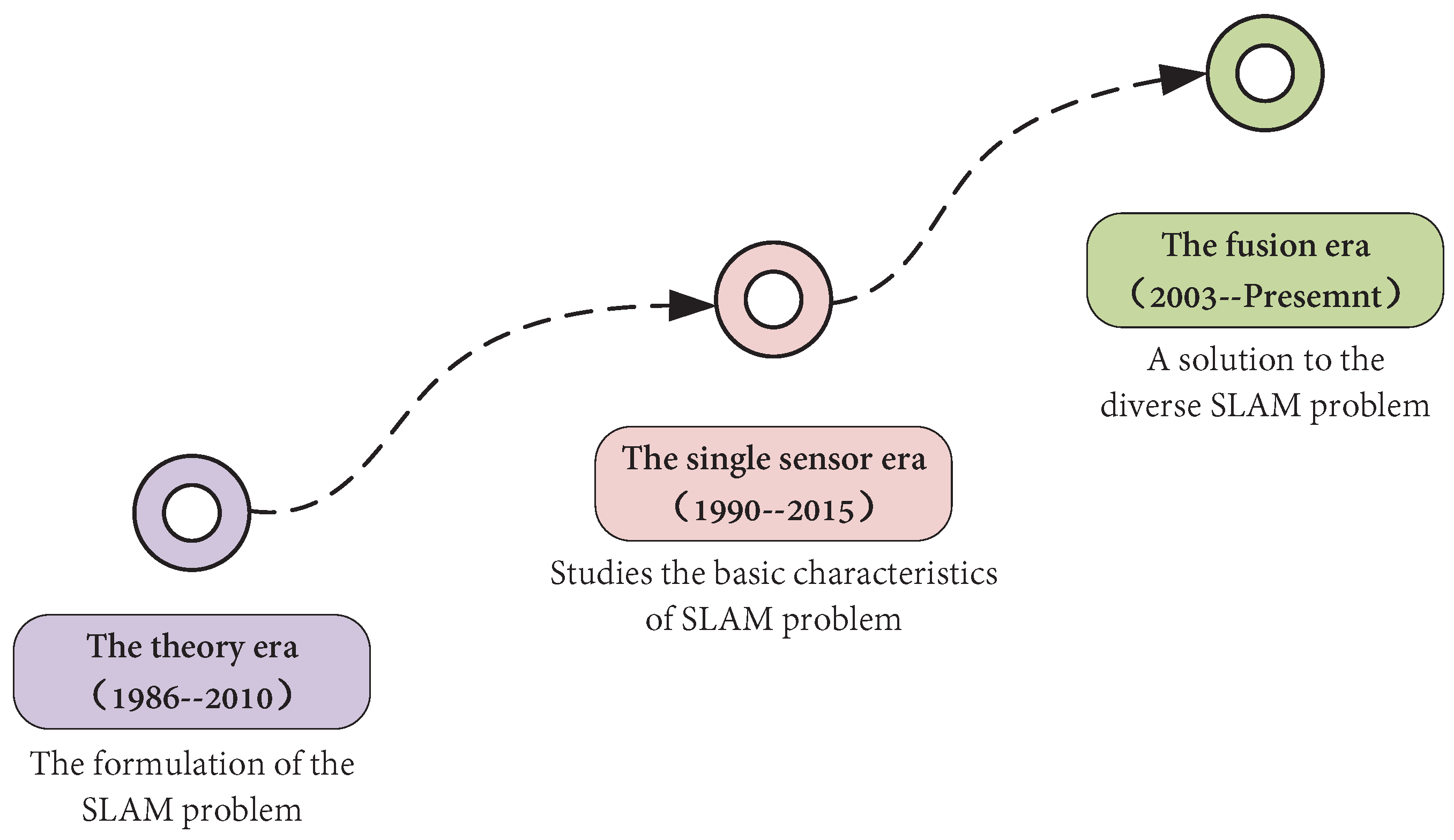
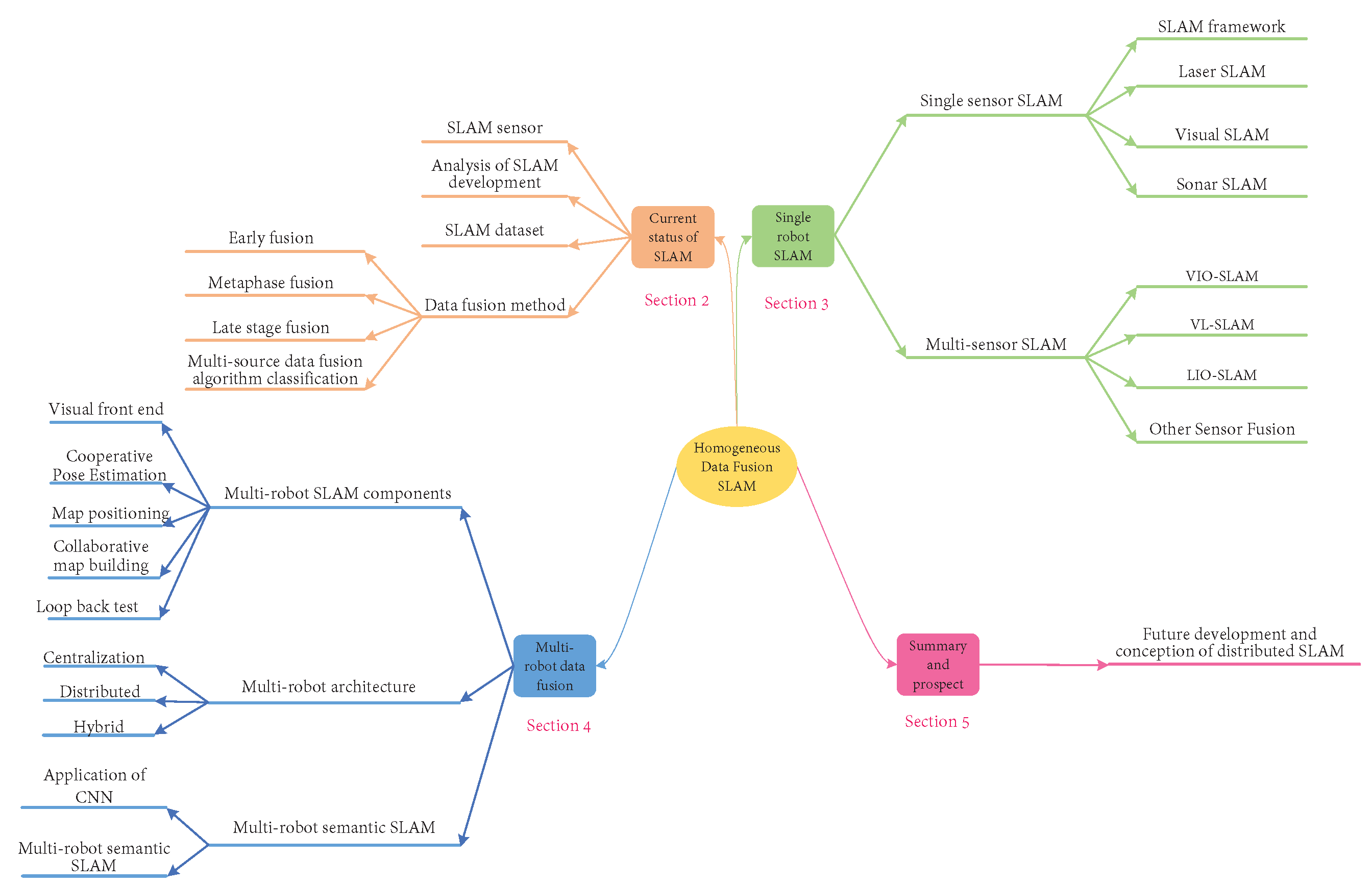
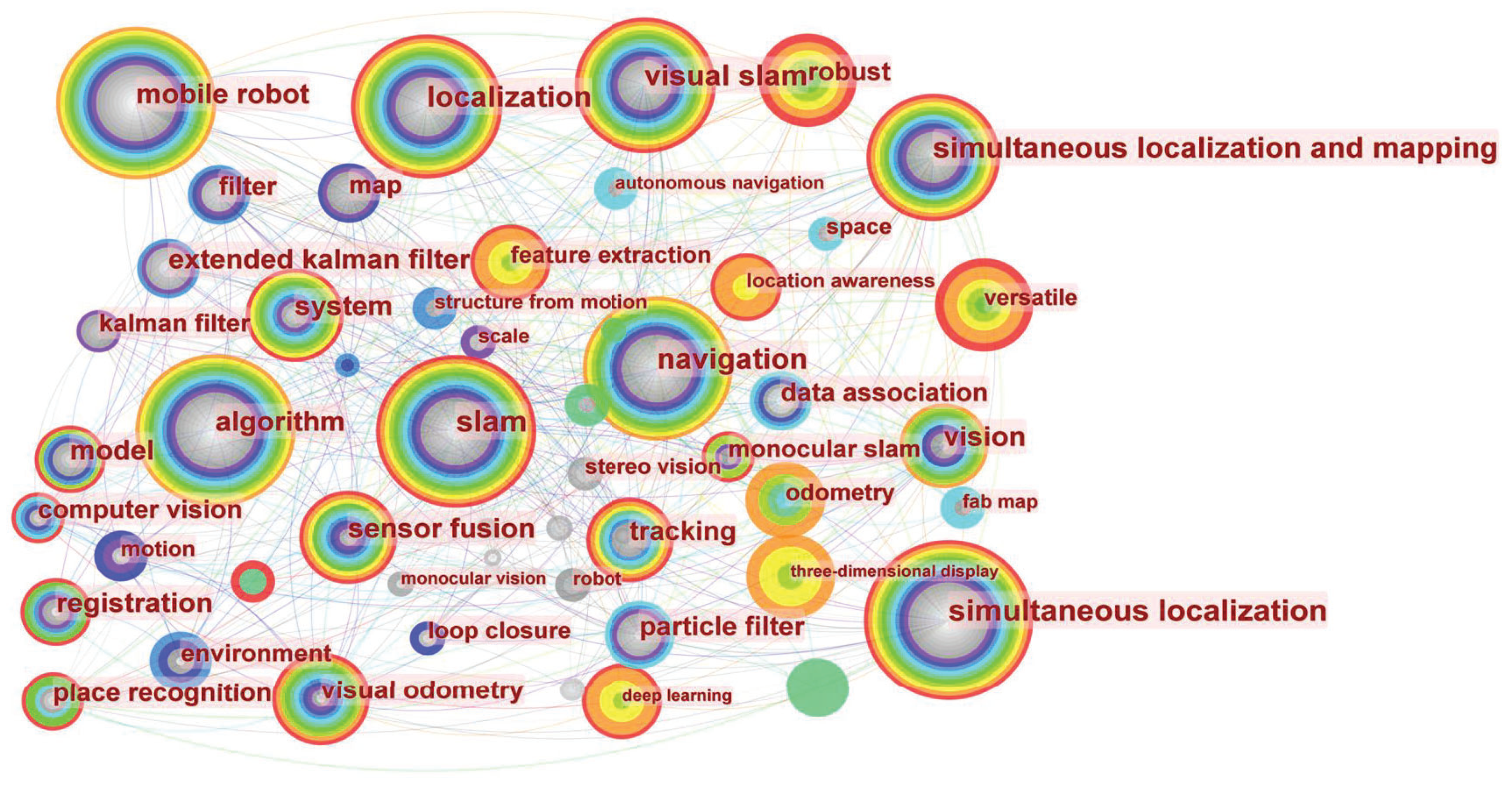
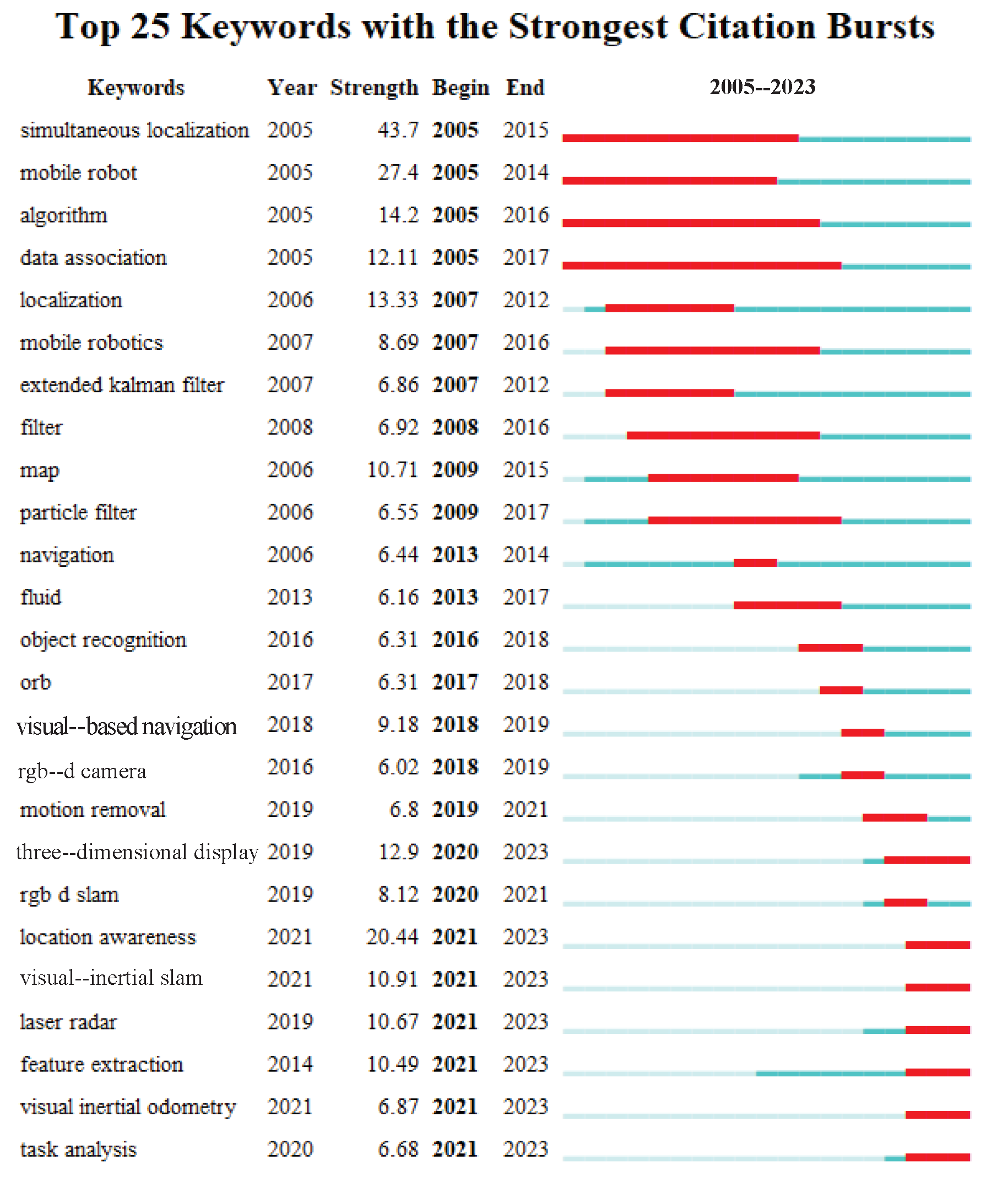
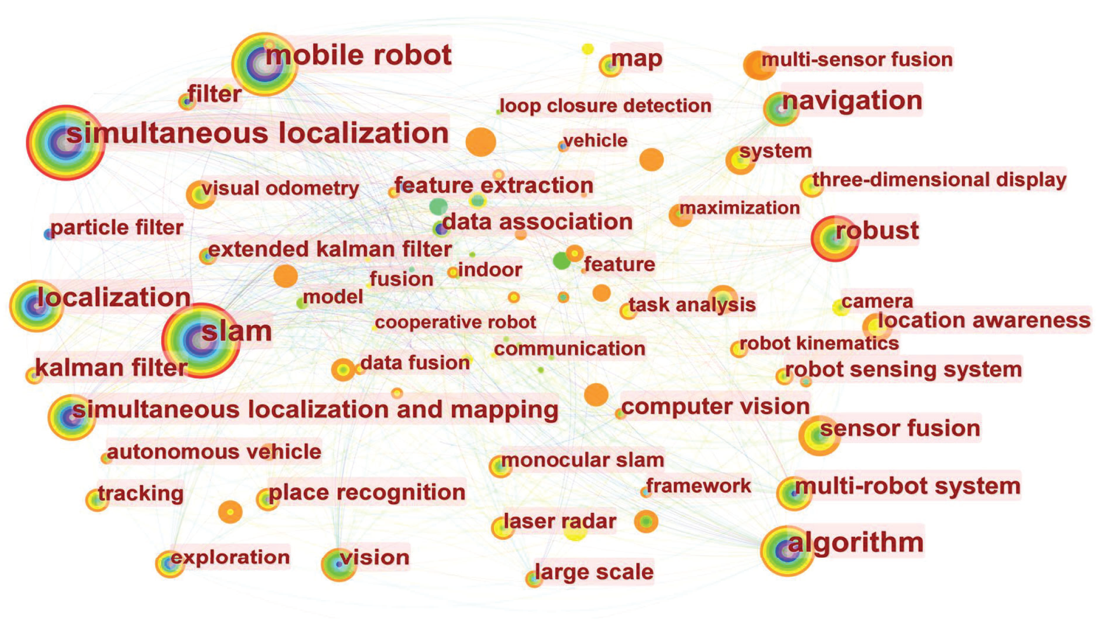
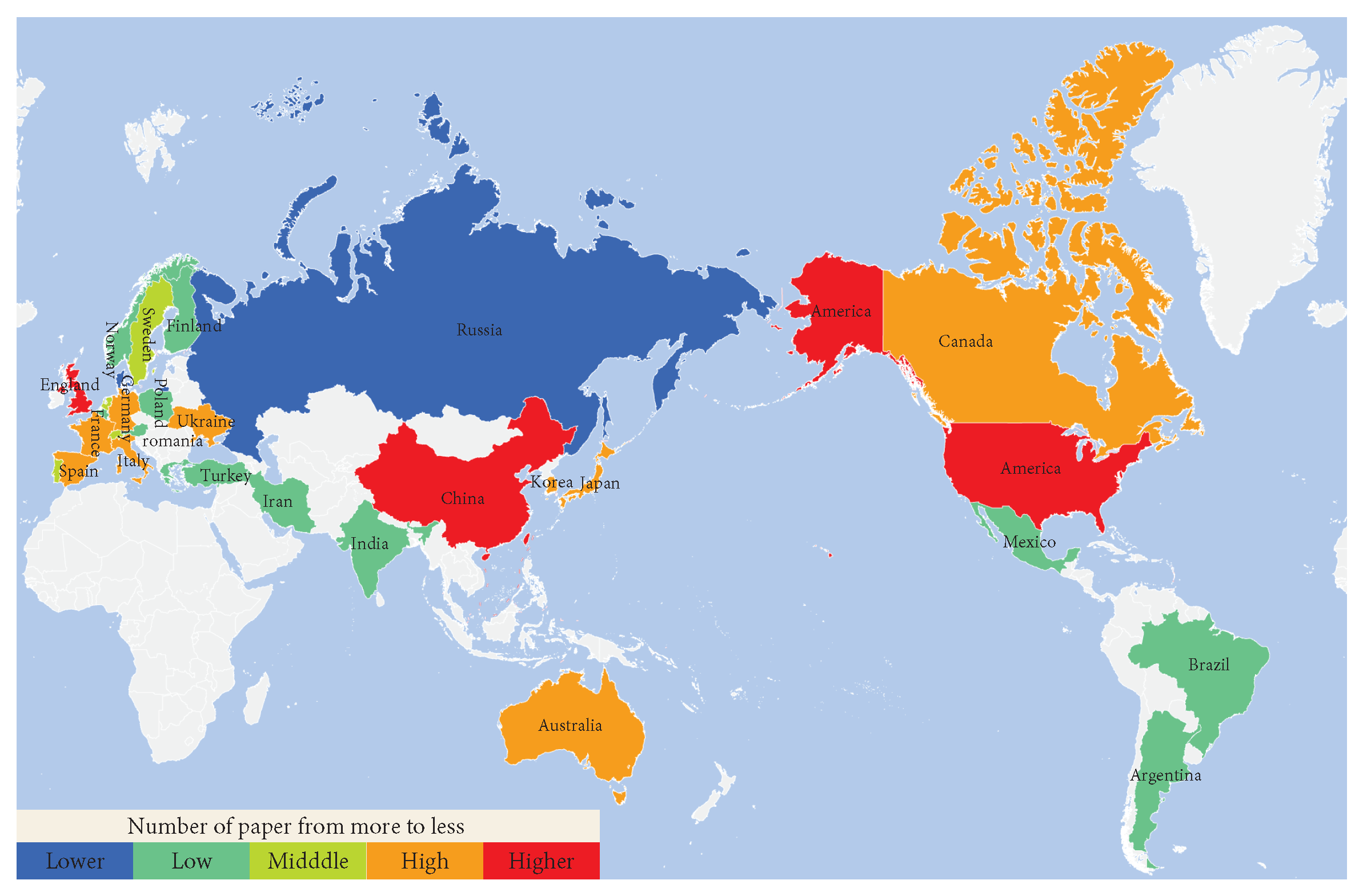
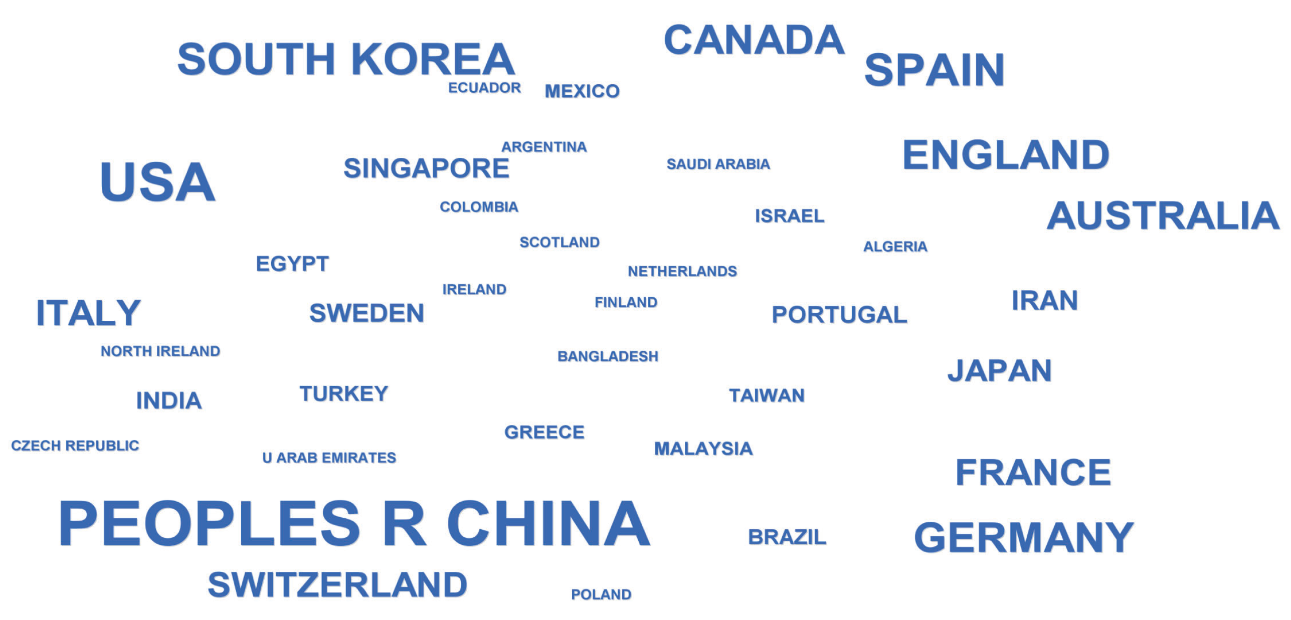
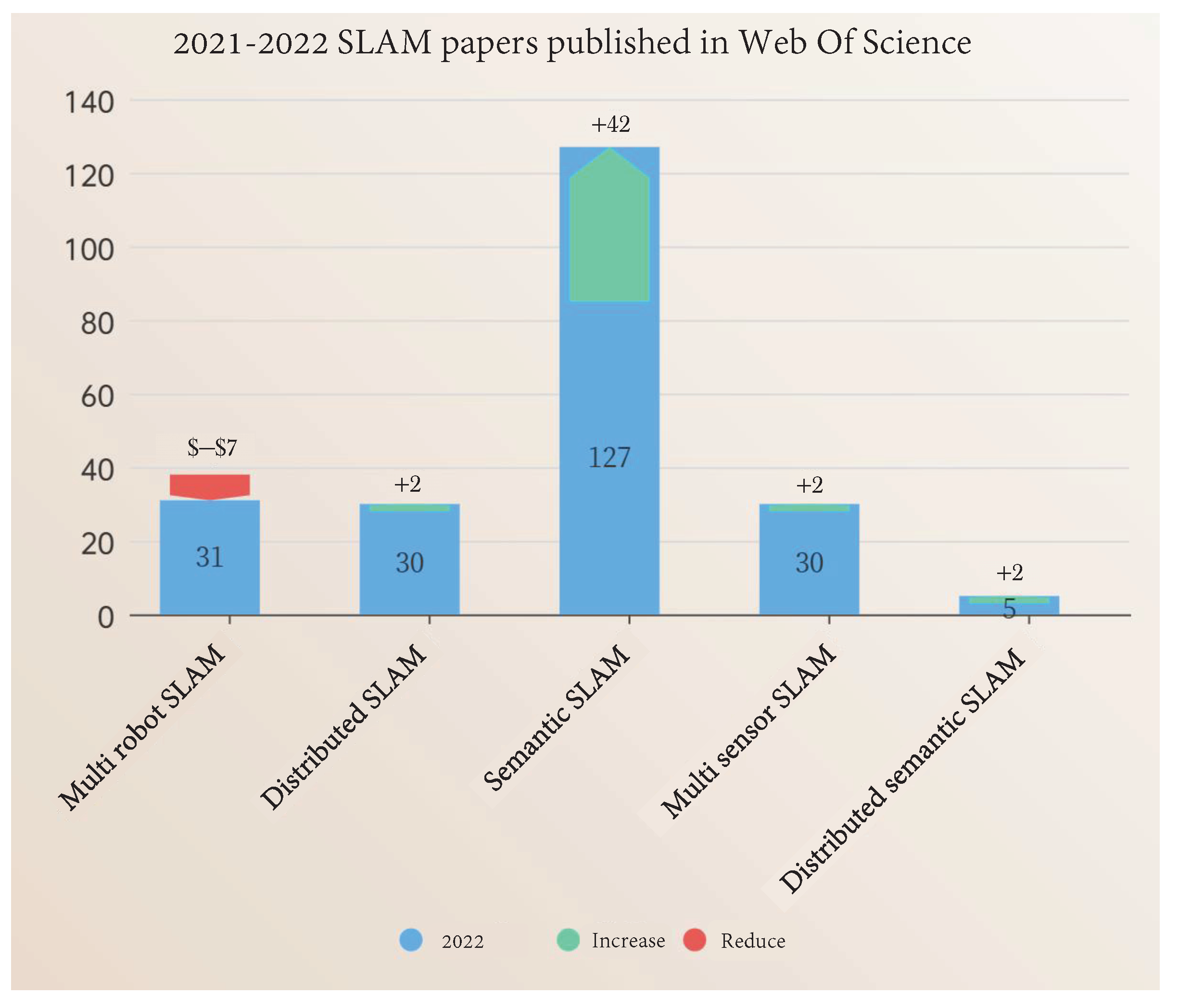
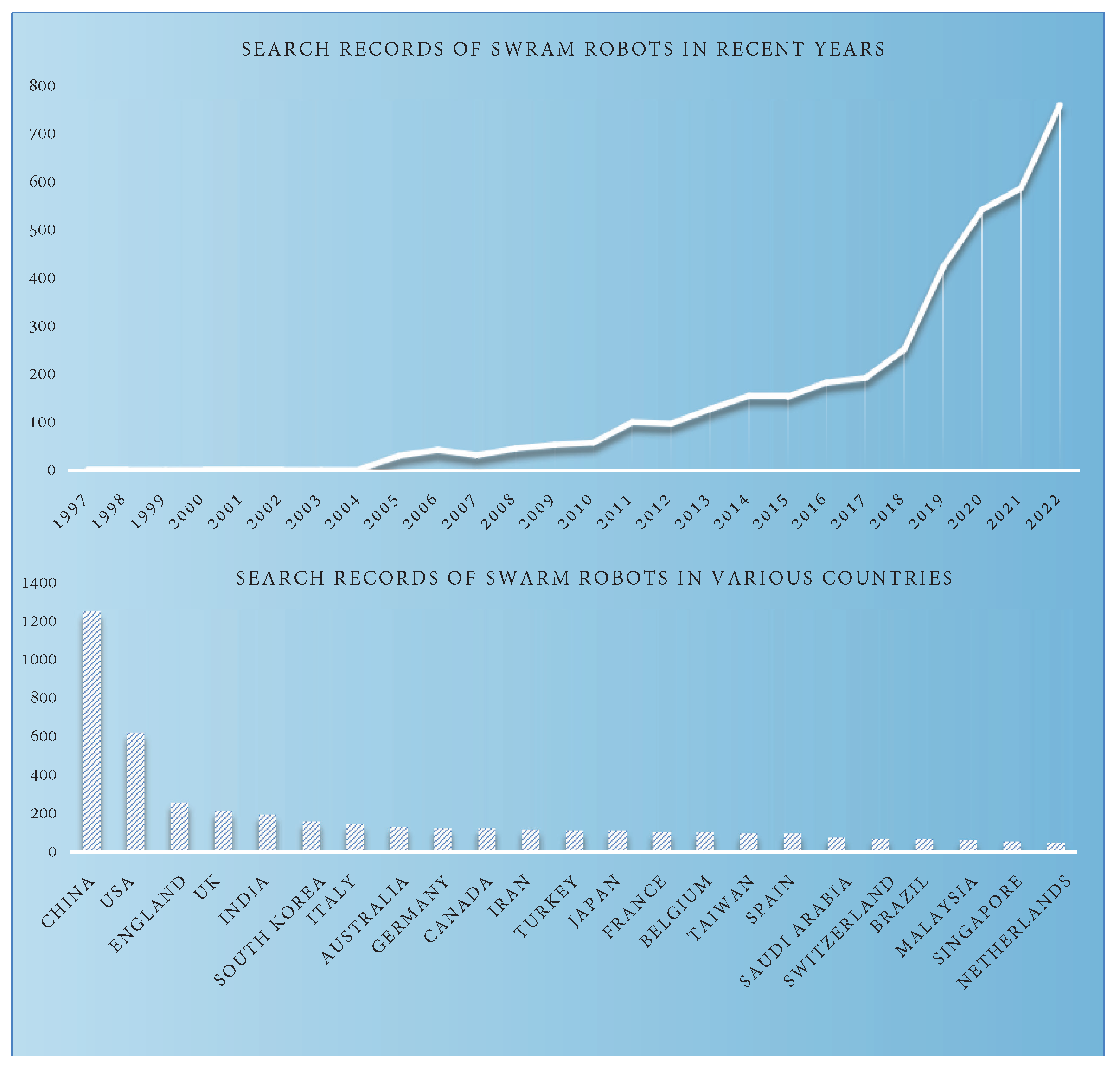
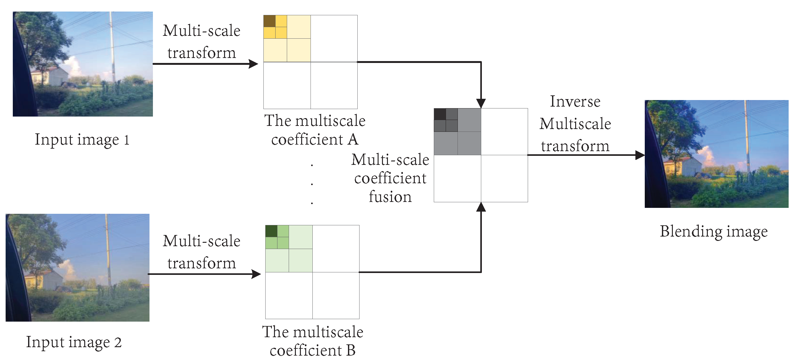
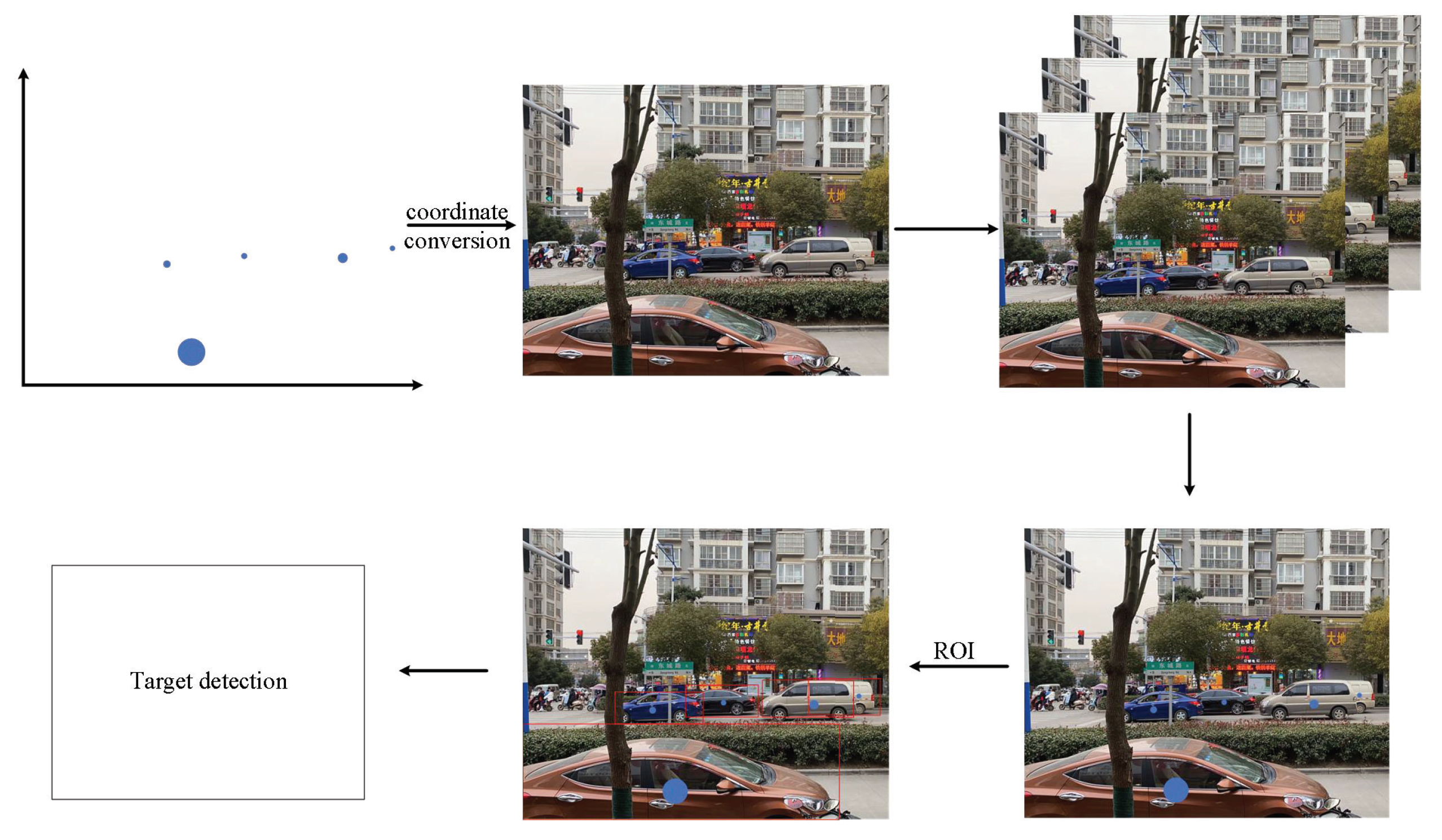
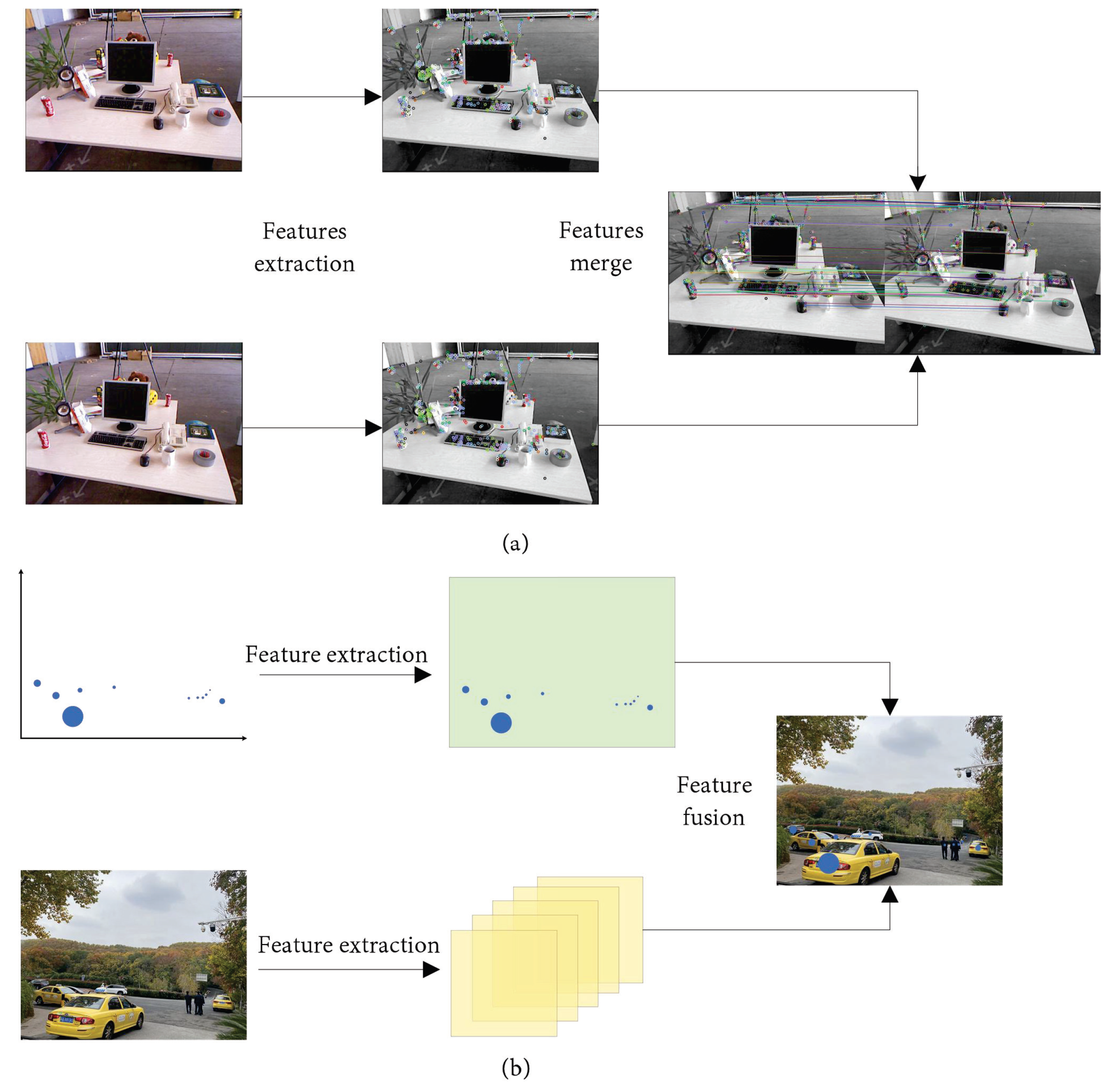
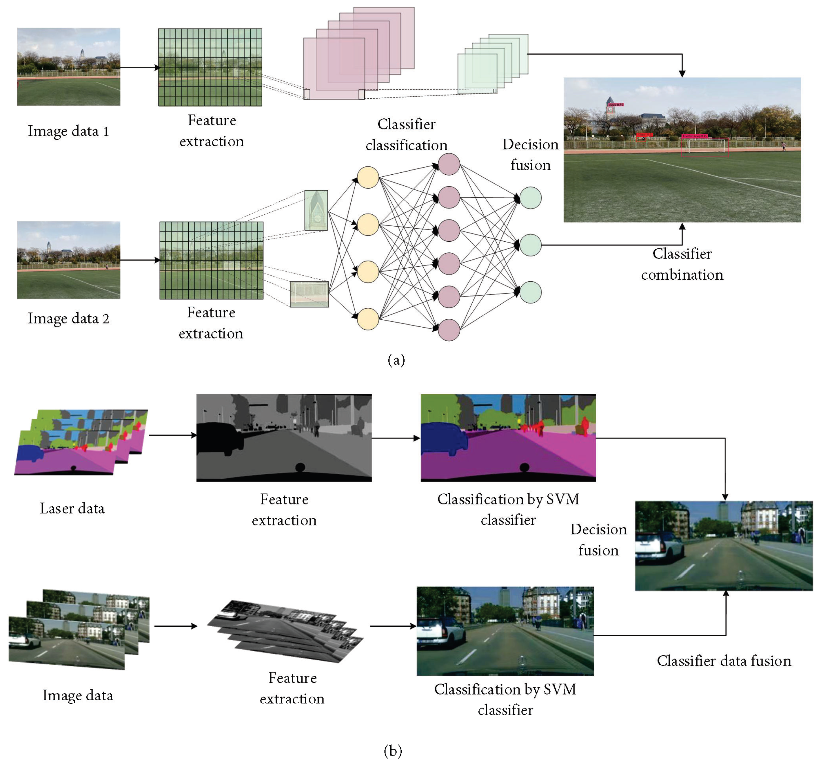
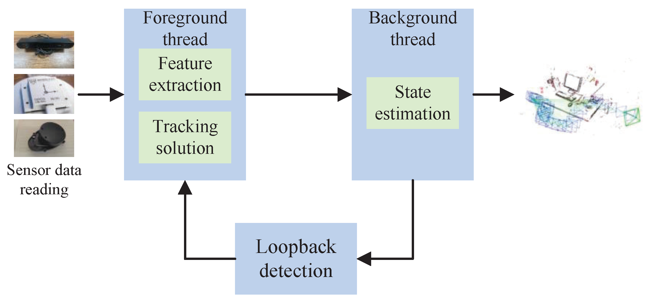
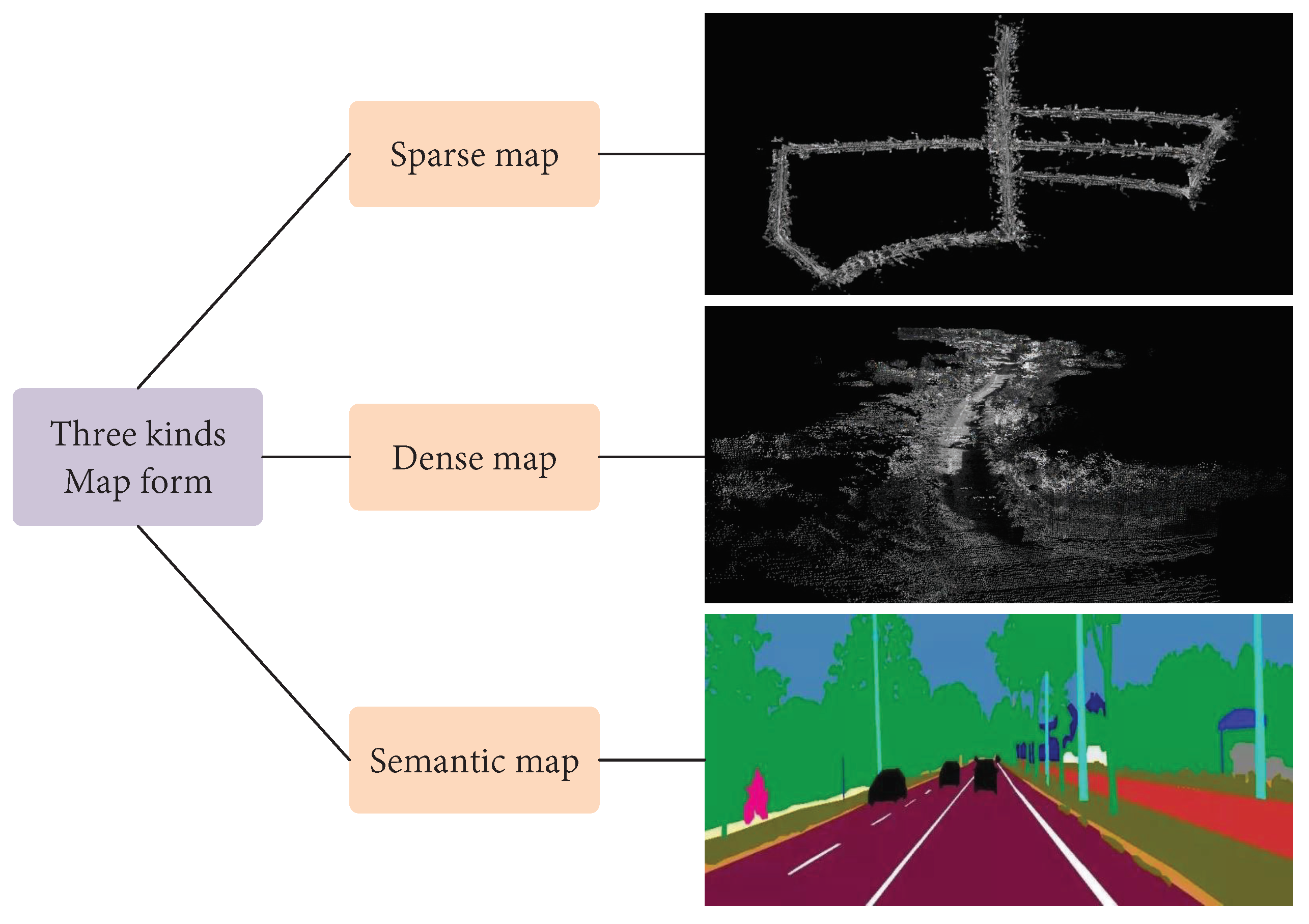
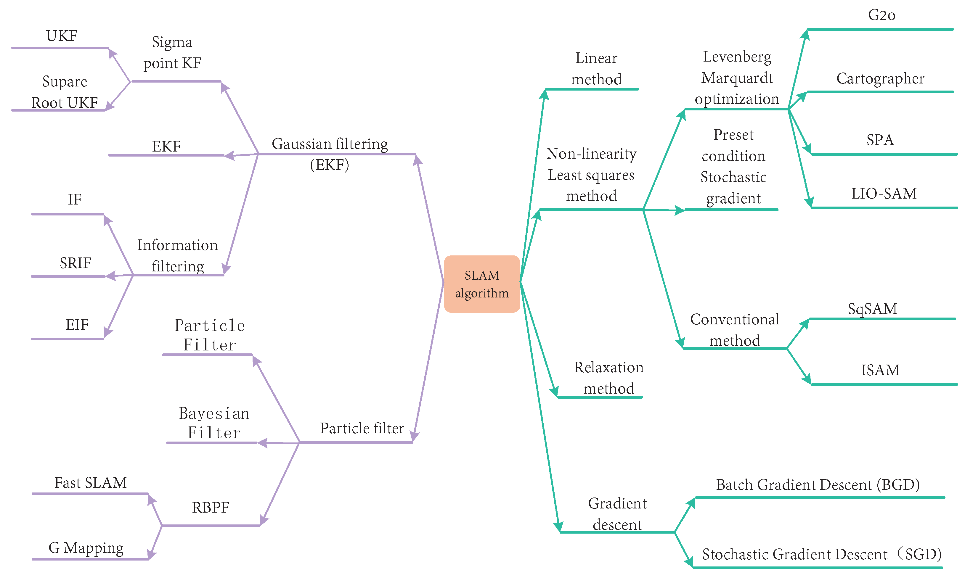
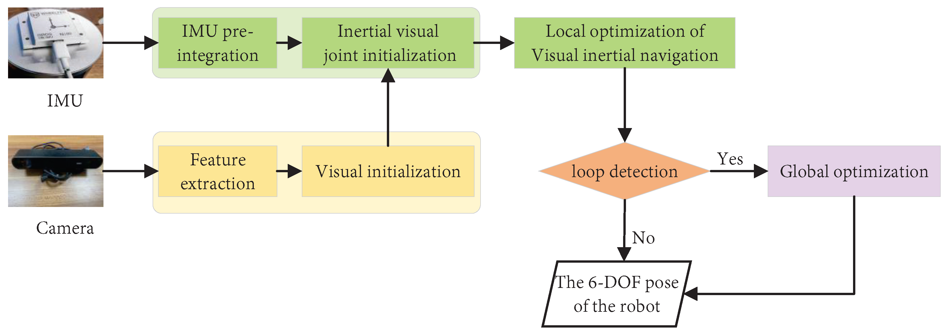
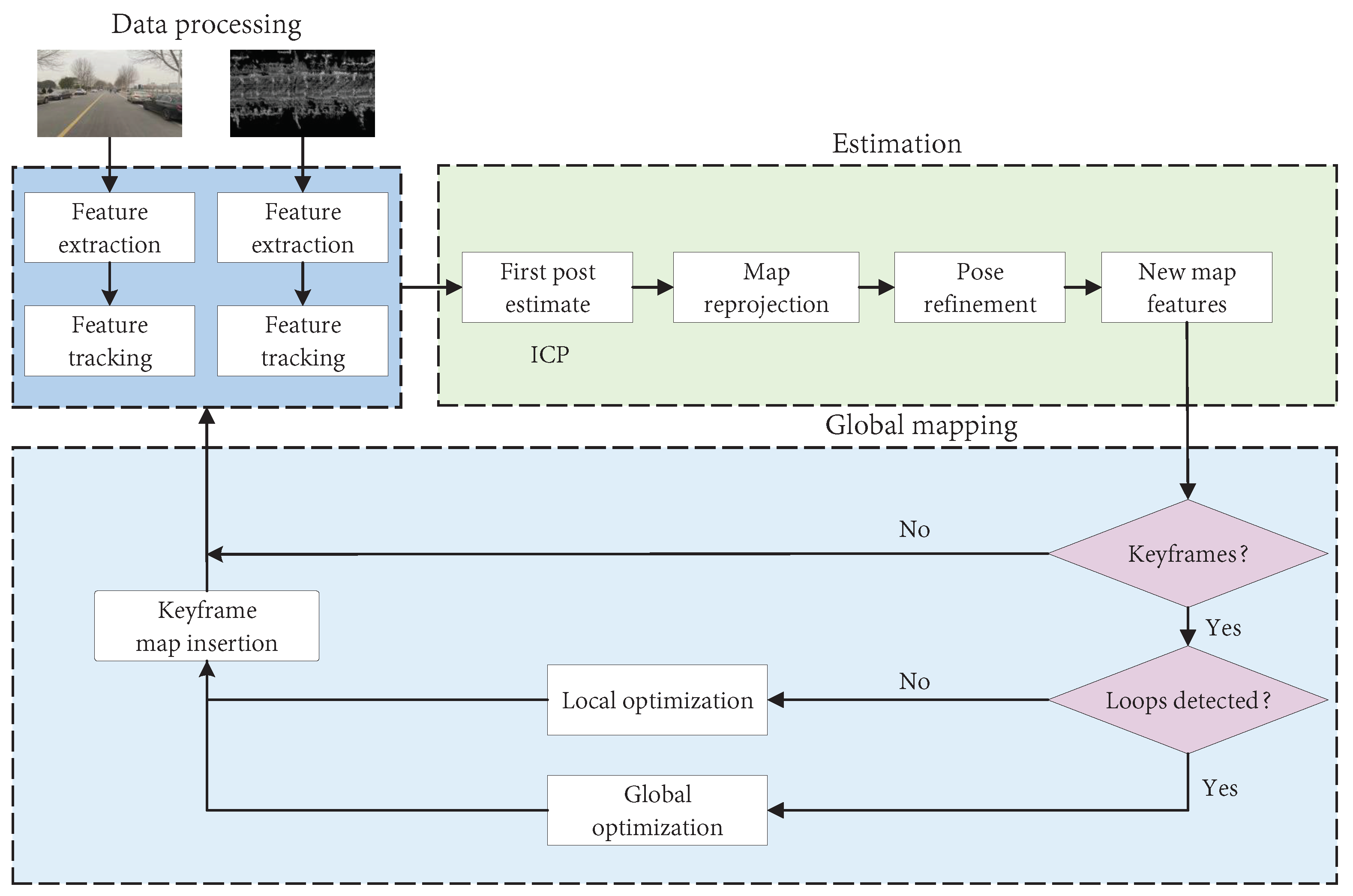
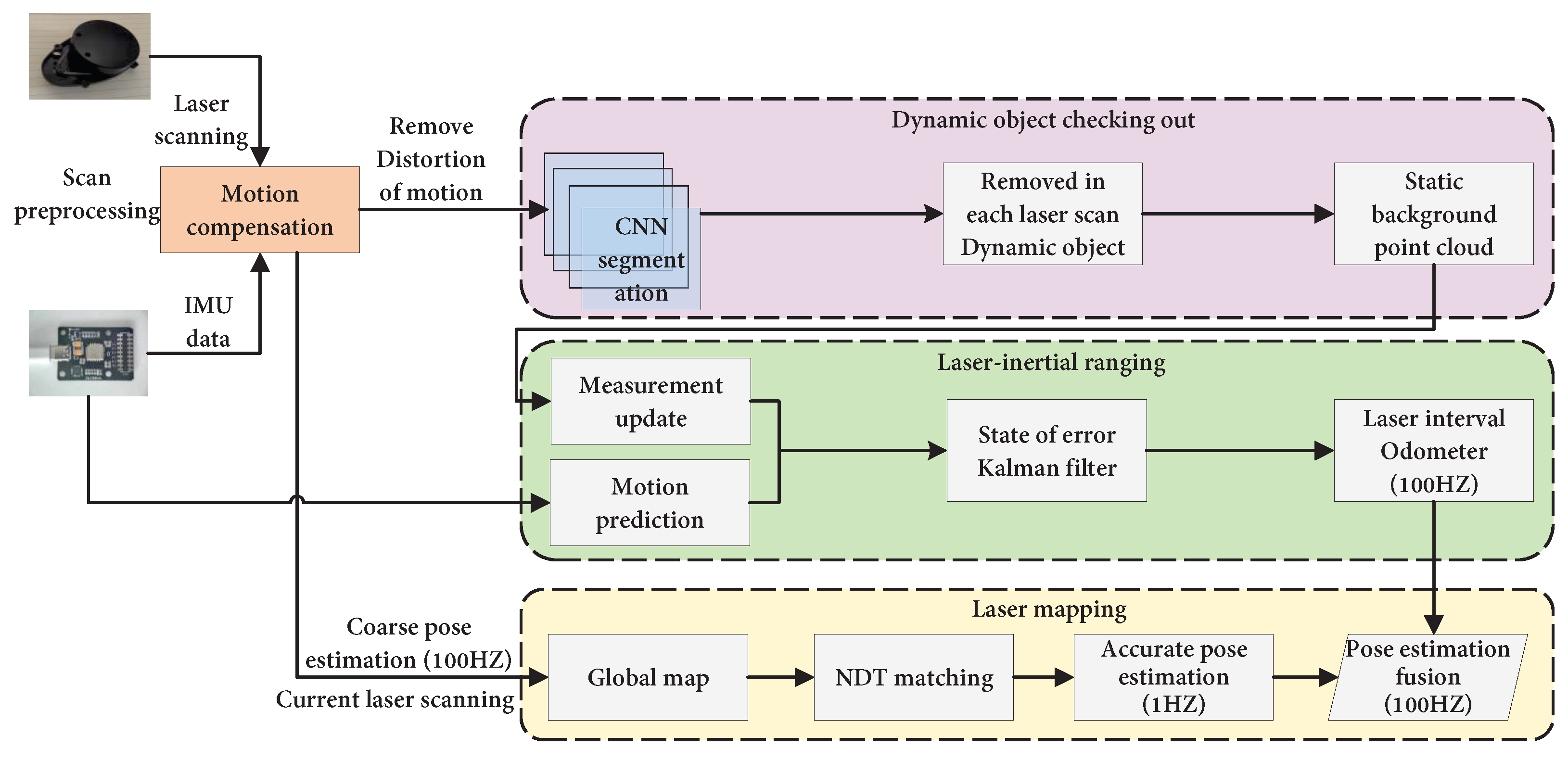
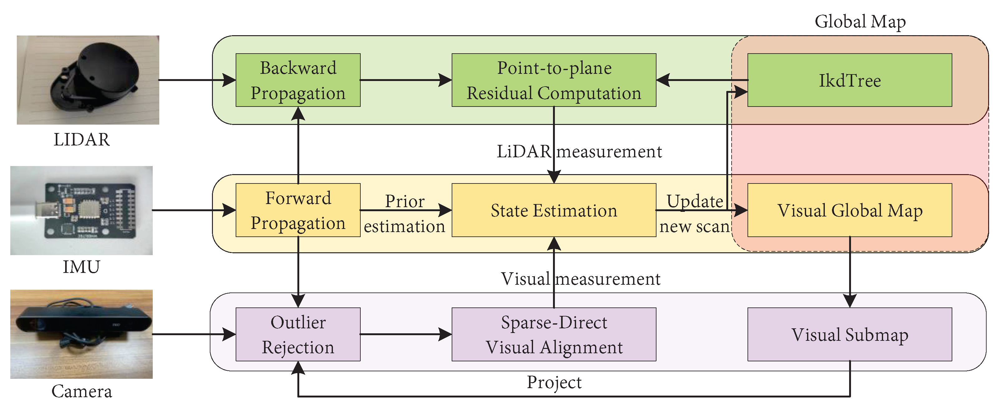
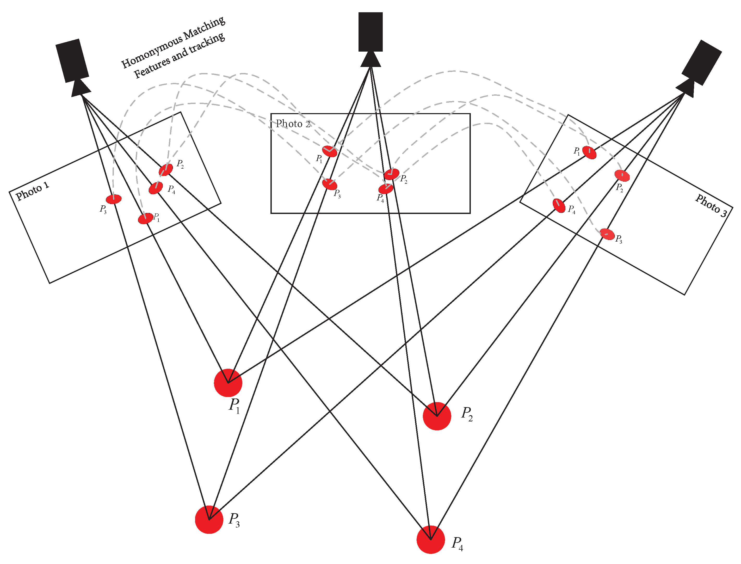
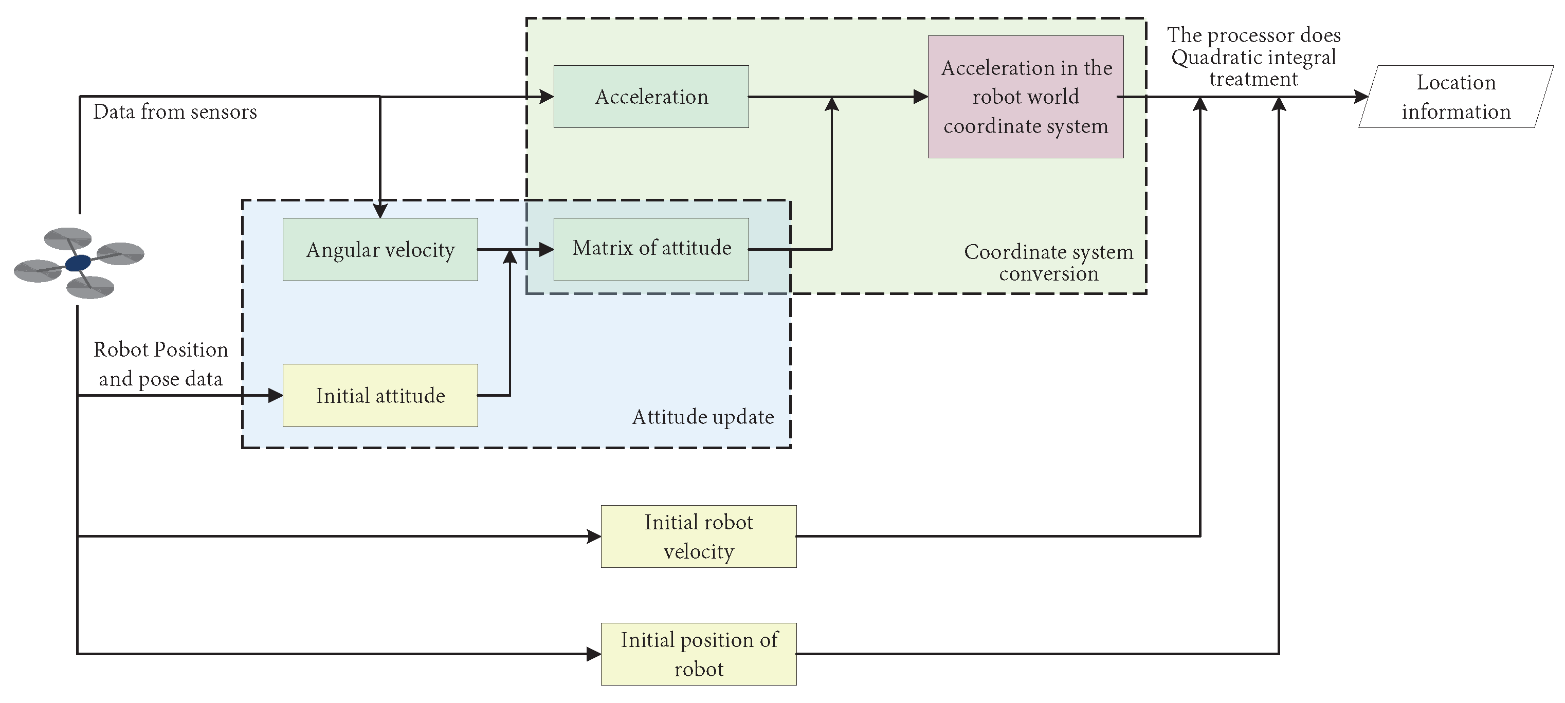
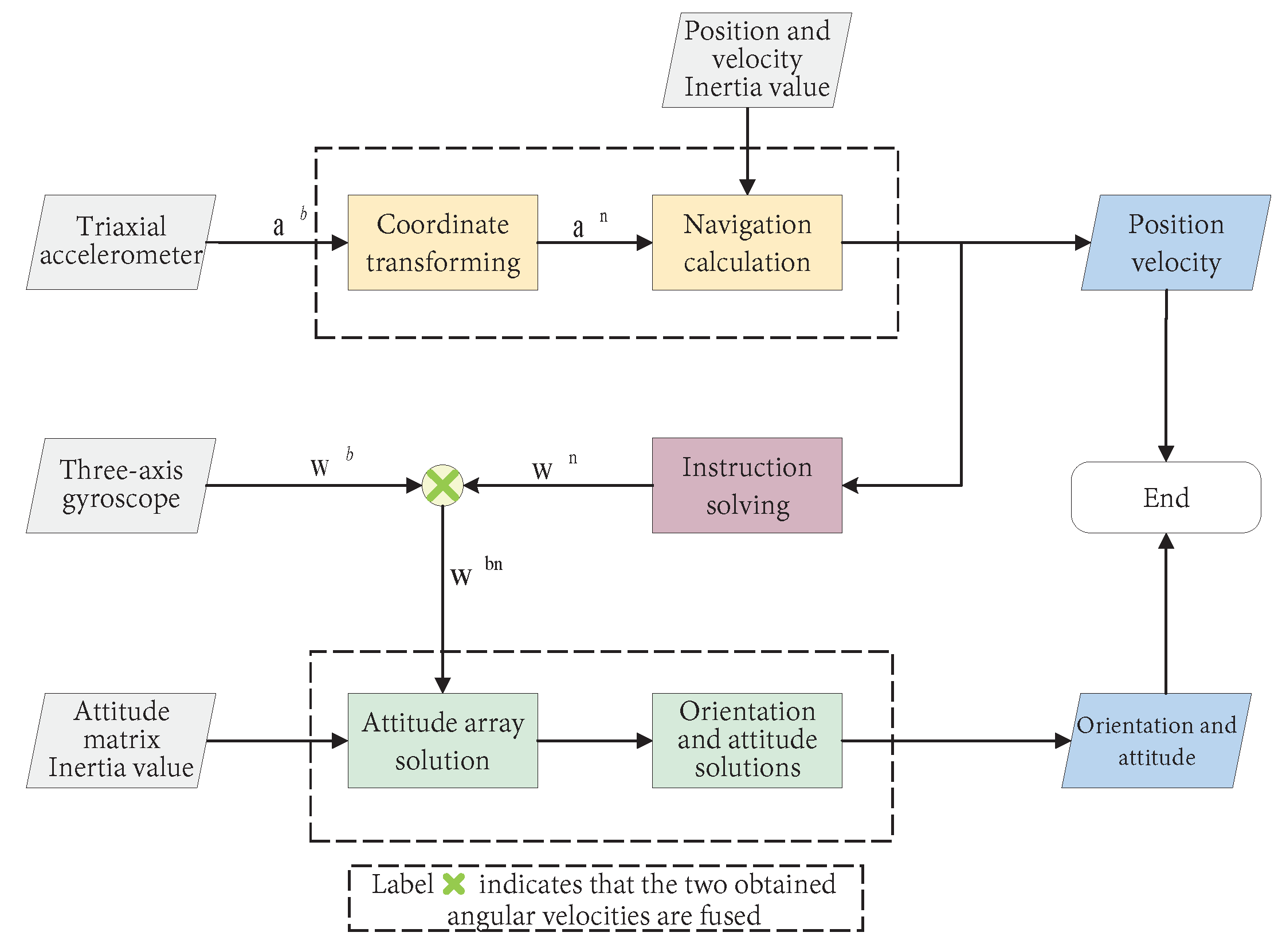
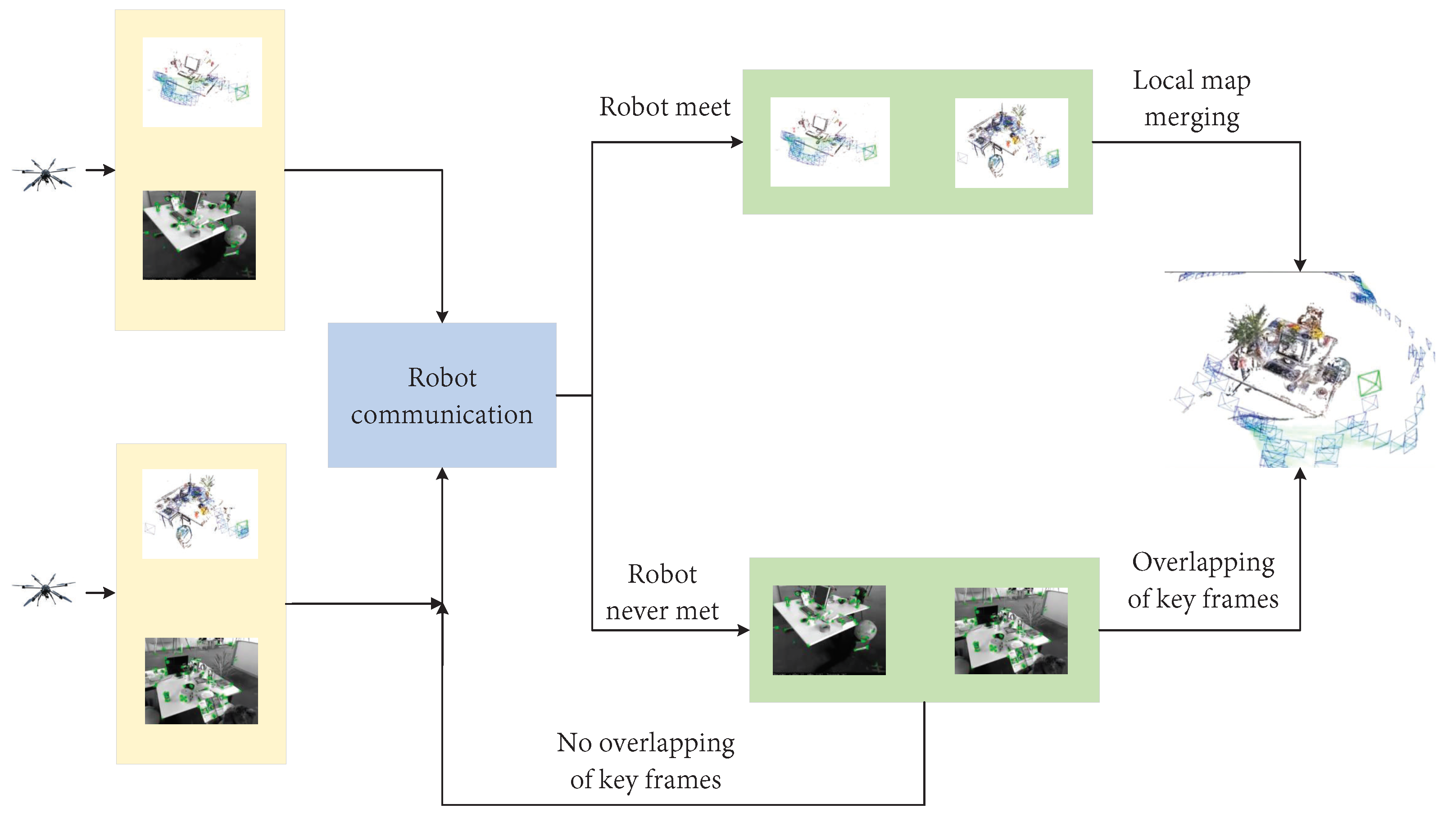
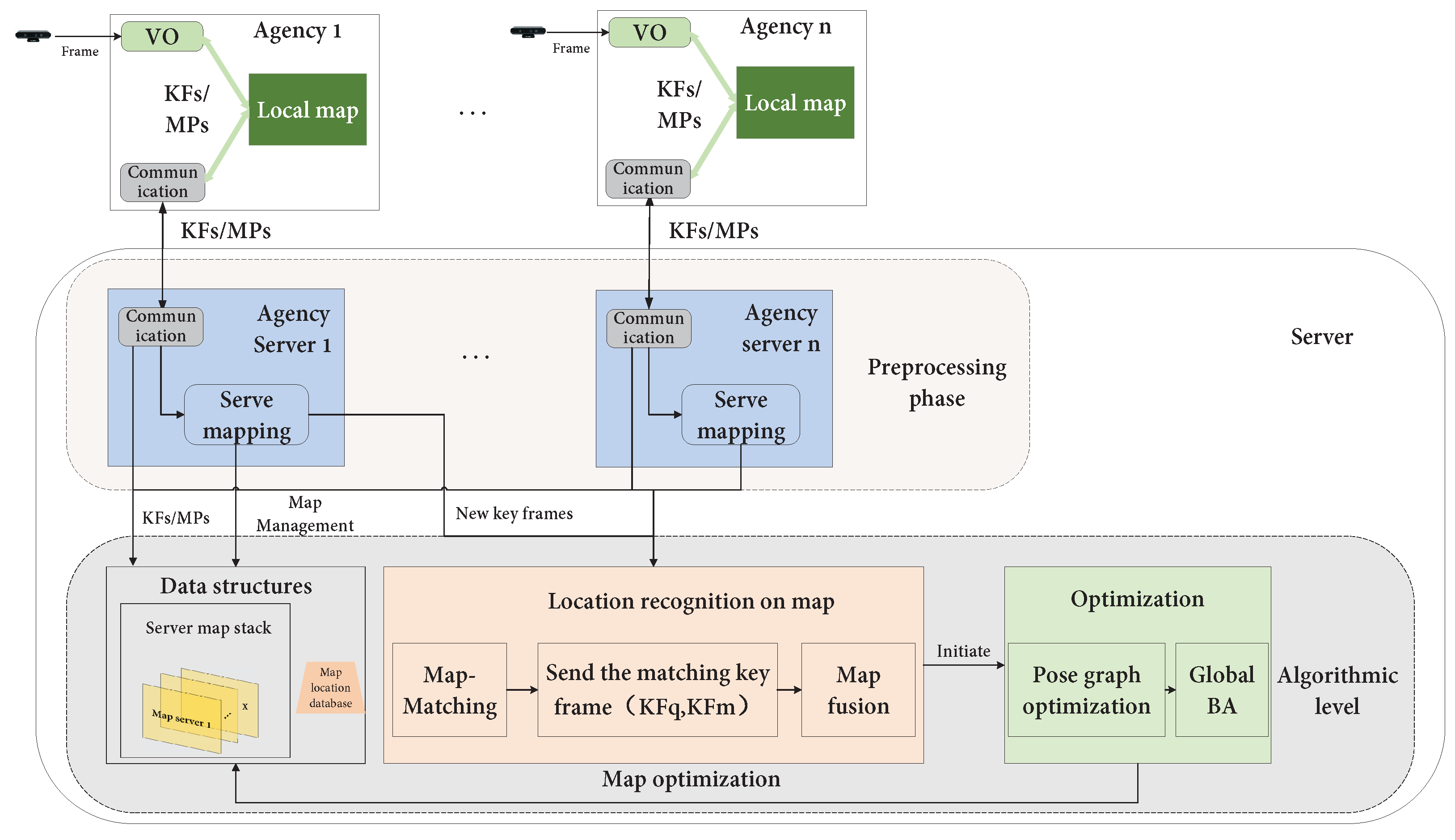
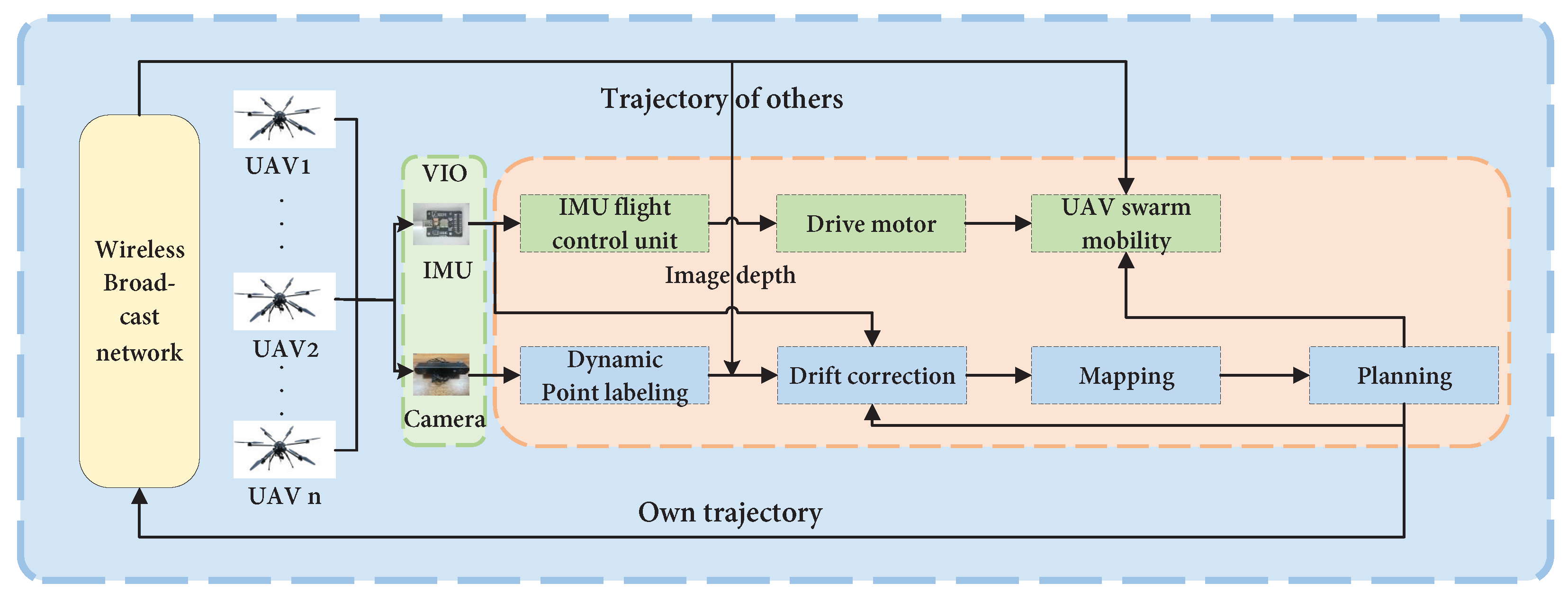
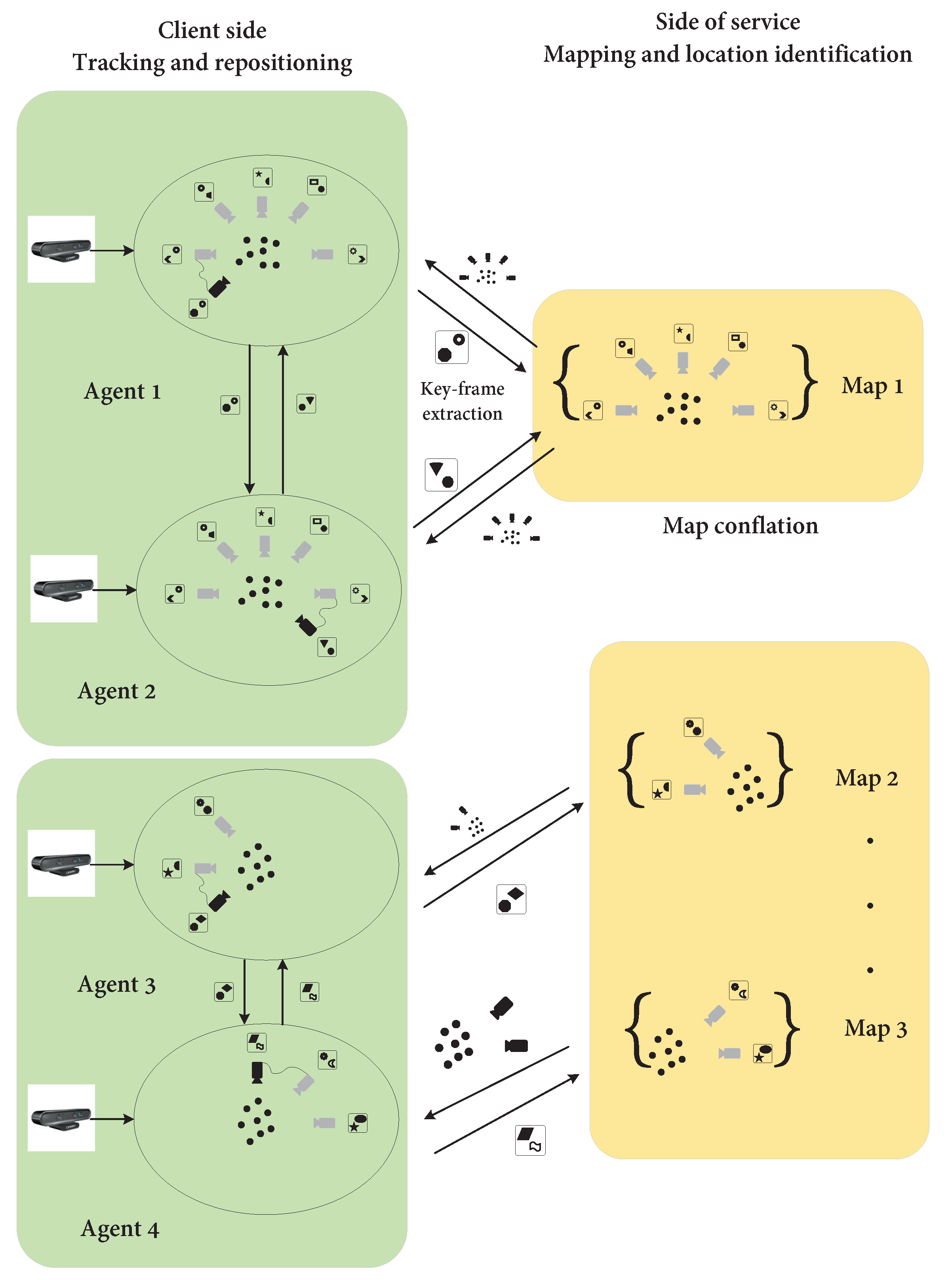
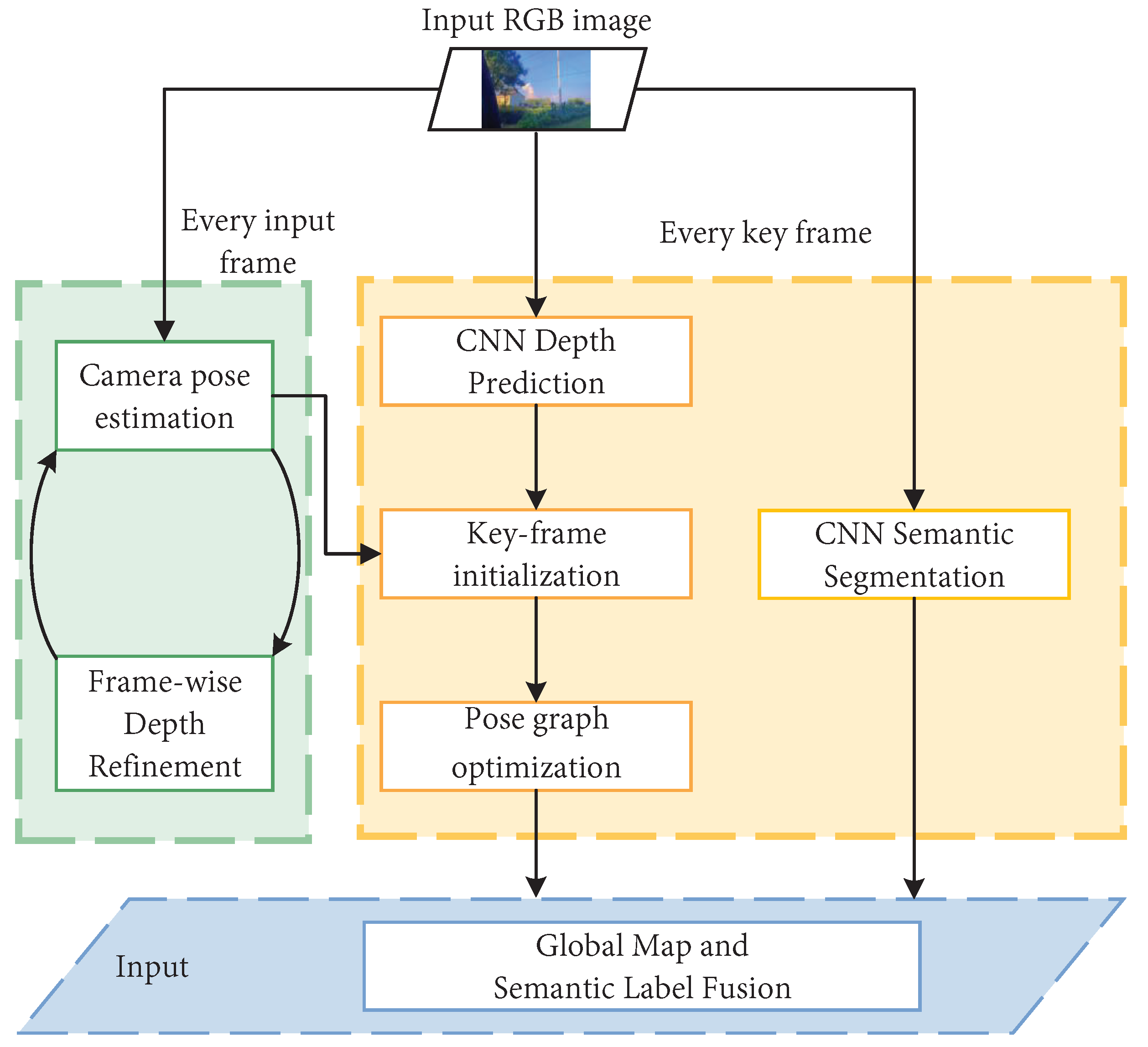
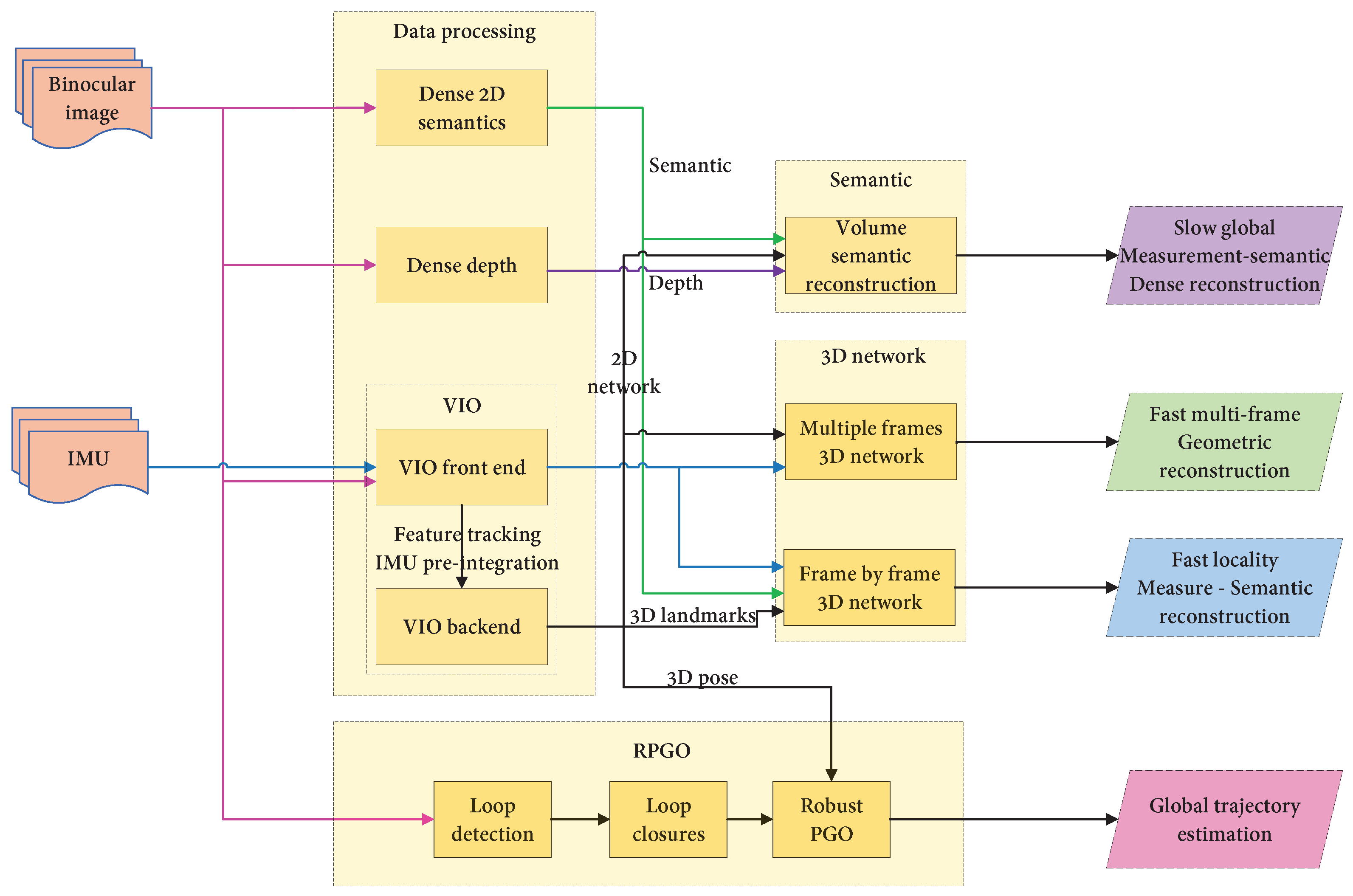
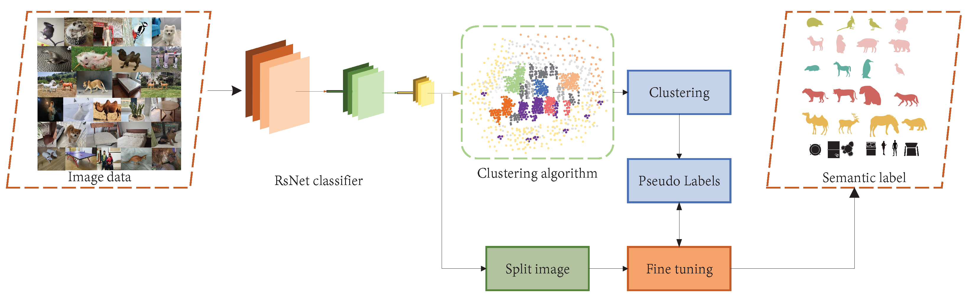
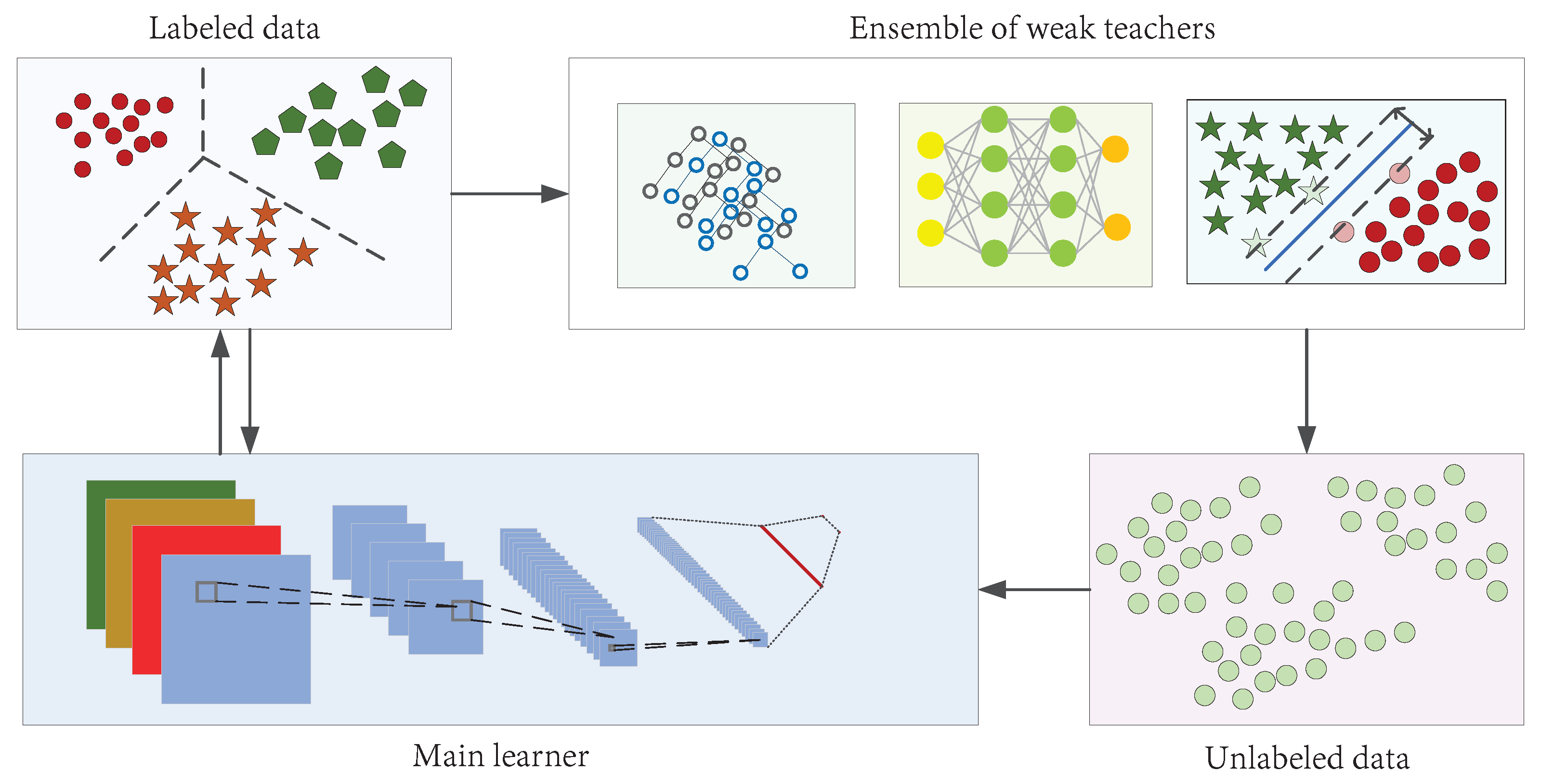
Figure 1. Different eras of SLAM development: the theoretical era, the single-sensor era, and the fusion era.
Machines 11 00653 g001
Figure 2. Framework of this paper. This paper consists of five parts, from the origin of SLAM to its development in the future, involving a comprehensive description of the development process of distributed SLAM and directions for future development.
Machines 11 00653 g002
Figure 3. Heatmap of keywords used in the field of mobile robot SLAM.
Machines 11 00653 g003
Figure 4. Keyword emergence map.
Machines 11 00653 g004
Figure 5. Heatmap of keywords used in the field of multi-robot SLAM.
Machines 11 00653 g005
Figure 6. Comparison of the number of papers published in various regions.
Machines 11 00653 g006
Figure 7. The degree of contribution of each region to the field of distributed SLAM: the larger the font, the higher the number of contributions to the distributed SLAM field.
Machines 11 00653 g007
Figure 8. Comparison of papers published in 2021 and 2022 for several important branches of SLAM development.
Machines 11 00653 g008
Figure 9. The number of publications related to swarm robots indexed in the Web of Science in recent years, as well as the number of papers produced by various countries.
Machines 11 00653 g009
Figure 10. Image integration method based on multi-scale [2].
Machines 11 00653 g010
Figure 11. Data-level-based image and radar data fusion [2].
Machines 11 00653 g011
Figure 12. The actual effect of mid-term (i.e., feature-level) fusion: (a) Feature-level fusion of heterogeneous data, (b) Feature-level fusion of homogeneous data [2].
Machines 11 00653 g012
Figure 13. Late data fusion (a) Decision–level fusion of heterogeneous data, (b) Decision–level fusion of homogeneous data [2,94].
Machines 11 00653 g013
Figure 14. Schematic diagram of the SLAM framework.
Machines 11 00653 g014
Figure 15. Three types of maps.
Machines 11 00653 g015
Figure 16. Summary of SLAM algorithms. Single-sensor SLAM methods were divided into two categories—according to traditional filtering methods and modern optimization algorithms—and the known SLAM algorithms with high frequency were classified. In this way, the structural diagram of the SLAM algorithms was obtained.
Machines 11 00653 g016
Figure 17. Schematic diagram of the VIO process. The system is composed of a vision module and an IMU module. It outputs bit pose data through local optimization and loop closure detection [161].
Machines 11 00653 g017
Figure 18. Schematic diagram of VL-SLAM [5]. The framework is divided into three steps. First, in the data processing step, feature detection and tracking is performed on the two modalities. In the estimation step, the vehicle displacement is first estimated from the tracked features, after which the map and feature landmarks are detected and matched. Pose optimization is performed after successful matching. Finally, the global optimization trajectory or local optimization trajectory is determined according to the detection of loop closure.
Machines 11 00653 g018
Figure 19. A loosely coupled LIO-SLAM model [90]. The system is composed of four sequential modules, including a laser inertial ranging module and a laser mapping module. Through the cooperation of the four modules, robust motion estimation and motion mapping in highway environments can be realized.
Machines 11 00653 g019
Figure 20. A kind of VIL-SLAM system structure diagram [198].
Machines 11 00653 g020
Figure 21. Basic principle of visual SFM (structure-from-motion).
Machines 11 00653 g021
Figure 22. Robot pose determination process.
Machines 11 00653 g022
Figure 23. Robot map positioning process [232] (IMU sensor combined with UWB for integrated navigation positioning). a b represents the acceleration value measured by the three-axis accelerometer, a n represents the acceleration value after a coordinate transformation; W b represents the angular velocity measured by the three-axis gyroscope, W n represents the angular velocity calculated by the general navigation, and the two are fused to obtain W b n and sent to the attitude array for solution.
Machines 11 00653 g023
Figure 24. Block diagram for determination of overlapping areas. An office map is taken as an example, where two robots build a map around a desk, communicate with each other after forming their mapping, and locally fuse the locations where the keyframes overlap when they meet. The keyframes are detected when the robots do not meet, and map fusion is performed when the keyframes overlap. When the keyframes do not overlap, the mapped data are used to communicate with the robots again.
Machines 11 00653 g024
Figure 25. Centralized architecture schematic diagram. The agent robot runs a real-time VO and maintains a local map of size N in its memory, as well as a communication module to exchange data (keyframes with map points and reference frames of the current position) with the server. Servers are ground stations that perform non-time-critical and computationally expensive processes.
Machines 11 00653 g025
Figure 26. Distributed architecture schematic diagram [3].
Machines 11 00653 g026
Figure 27. Example hybrid architecture model. Using the PTAM (parallel tracking and mapping) system as the basic framework, the system sends the expensive computing tasks to a high-performance server to run the cloud service execution. The system can run multiple tracking threads on the same map data. The small circles in the figure represent the keyframes of the actual scene, and the figures in the rounded rectangles represent the keyframe shape observed by the camera from a given angle, where the keyframe shape observed by the camera from each angle is not the same. Through mutual communication and the processing of the cloud server, a map aligned with the actual environment is obtained.
Machines 11 00653 g027
Figure 28. The CNN–SLAM structure [270].
Machines 11 00653 g028
Figure 29. Kimera 3D distributed semantic map construction. VIO quickly performs locally accurate 3D pose estimation, Mesher performs fast local 3D mesh reconstruction and avoids inter-robot collisions. The global 3D mesh is constructed using the volume method and annotated semantically.
Machines 11 00653 g029
Figure 31. A semi-supervised semantic extraction algorithm. By learning the labeled data, the weak set data are clustered, allowing for the generation of semantic labels for the unlabeled data.
Machines 11 00653 g031
Table 1. Two representative categories of laser sensors.
Type2D Laser Radar3D Laser Radar
CharacteristicIt can scan and identify the obstacles in the plane and can update the status in real-time, small in size and lightweight.It can scan and identify obstacles in the three-dimensional plane, has high measurement accuracy, wide measurement range, strong anti-interference ability, strong penetration ability, and can respond quickly in dynamic and static states.
Principal manufacturerSure Star, Robo Sense, Innoviz, LeddarTechSLAMTEC, Hensai Technology, Velodyne, Quanergy
Representative productsXD–TOF–10HM, XD–TOF–10HULTRA Puck VLP–32C, Leddar M16,VLS–128
Chief applicationObstacle monitoring, unmanned rangingUnmanned driving, terrain mapping
Table 2. The number and type of sensors used in common driverless cars.
CompanyType of CarNumber of CamerasNumber of Radar SensorsNumber of Ultrasonic Sensors
ZhijiZhi ji L712512
TeslaModel 38112
LynkCoMobileye12512
XpengXpeng P714512
IdealIdeal ONE5512
BMWBMW iX5512
Mercedes BenzEQS5612
HondaHonda Flagship Legend51012
Table 3. Common vision sensors.
Camera TypeManufacturerConfigurationMeasuring RangeApplicable Scene
D435IIntelBinocular + TR active infrared0.1–10 mIndoor/Outdoor
Kinect2MicrosoftTOF0.5–4.5 mIndoor
ZEDStereolabsBinocular0.3–25 mOutdoor
FS830-BDPercipioStructured light0.5–5.5 mIndoor
D1000-IR-120MYNTBinocular + IR active infrared0.37–7 mIndoor
Table 4. Commonly used data sets in SLAM.
Data SetYearUnit of SupplyCameraRadaIMUMoving ObjectSurroundings
UTIAS [53]2011University of Toronto Institute of Aeronautics and Astronautics1 × Monocular cameraNNUGVs (5)Nine individual data sets
KITTI [54]2012Karlsruhe Institute of Technology, Germany, Toyota2 × Color camera, 2 × Grayscale cameraYYCarOutdoor 39.2 km
TUM RGB-D [55]2012Munich Industrial University1 × RGB-DNNHandheld and wheeled robots39 indoor sequences
NYUDv2 [56]2012New York University1 × Color camera, 1 × RGB-DNNHandheld and wheeled robots1449 annotated RGB images and depth maps, 407,024 unlabeled images
ICL-NUIM [57]2014Royal Academy of London1 × RGB-DNNHandheld and wheeled robots8 sets of outdoor sequences
EuRoC [58]2016ETH Zurich1 × Binocular grayscale cameraNYUAV11 sets of indoor/outdoor sequences
Oxford Robotcar [59]2017Oxford university6 × Color cameraYNCar100 sets of outdoor/urban sequences
Scan Net [60]2018Stanford University1 × RGB-DNNHandheld camera21 sets of indoor sequences
Re Fusion [61]2019University of Bonn1 × RGB-DNNHandheld robot26 sets of outdoor sequences
Cityscapes [62]2019Darmstadt University of TechnologyStereo cameraNNCar19 sets of outdoor sequences
Air Museum [63]2020French aerospace laboratory2 × Stereo monochrome cameraNY3 × Wheeled robot, 1 × UAVFive interior scenes
S3E [64]2022Sun Yat-sen University1 × Stereo cameraYYUGVs (3)Seven outdoor scenes, five interior scenes
Y indicates that the sensor is used in the data set; N indicates that the sensor is not used in the data set.
Table 5. The main SLAM laboratories.
LaboratoryResearch DirectionWebsite Link
ETH ZurichCreate robots and intelligent systems that can operate autonomously in complex environments.https://asl.ethz.ch/ (accessed on 14 June 2023)
University of MinnesotaVision-/laser-assisted inertial navigation systems, multi-robot/-sensor positioning, optimal information selection and fusion, mobile operation, human–machine cooperation, and so on.http://mars.cs.umn.edu/ (accessed on 14 June 2023)
Munich Industrial UniversityImage-based 3D reconstruction, optical flow estimation, robot vision, visual SLAM, and so on.https://cvg.cit.tum.de/research (accessed on 14 June 2023)
Hong Kong University of Science and TechnologyTightly coupled algorithm for visual–inertial navigation based on UAV. Representative work: VINS-Mono.https://uav.hkust.edu.hk/ (accessed on 14 June 2023)
Zhejiang UniversitySLAM, AR, 3D reconstruction. Representative achievements: RKSLAM, ACTS, swarm drones.http://www.cad.zju.edu.cn/english.html (accessed on 14 June 2023)
Wuhan UniversityComputer vision, remote sensing imaging, SLAM, image and video processing and analysis, robot vision navigation and positioning, multi-sensor integration.https://cvrs.whu.edu.cn/ (accessed on 14 June 2023)
Institute of Automation, Chinese Academy of Sciences3D computer vision, including camera calibration as well as 3D reconstruction, pose estimation, vision-based robot navigation, and vision services.http://vision.ia.ac.cn/index.html (accessed on 14 June 2023)
Tsinghua UniversityComputational photography, brain science and international frontiers of artificial intelligence, biological intelligence, computational imaging.http://media.au.tsinghua.edu.cn/english/index/index.html (accessed on 14 June 2023)
Carnegie Mellon UniversityRobot perception, structure, service type, field machines.https://www.ri.cmu.edu/ (accessed on 14 June 2023)
University of California, San DiegoMulti-modal environment understanding, semantic navigation, autonomous information acquisition.https://existentialrobotics.org/index.html (accessed on 14 June 2023)
TU Munich3D reconstruction, robot vision, deep learning, visual SLAM, and so on.https://cvg.cit.tum.de/research/vslam (accessed on 14 June 2023)
Table 6. Comparison of the advantages and disadvantages of the three fusion levels.
Fusion TypeEarly FusionMid-Term FusionLate Fusion
Fusion levelData levelFeature levelDecision level
Common algorithmWeighted mean; optimization methods; artificial neural networks [95]; color space fusionPrincipal component analysis; linear discriminant analysis; neural networksMajority voting [85]; average value fusion; Bayesian rule fusion [86]; ensemble learning; Dempster–Shafer (D-S) [88]; fuzzy set theory [96]
Table 7. Comparison of filter-based and non-linear optimization algorithms.
AlgorithmFiltering MethodNon-Linear Optimization Method
AdvantageSimple method. In the case of limited computing resources and simple estimation, the filtering method represented by EKF is more effective and is commonly used in laser SLAM.It can be globally optimized and works well.
DisadvantageNot suitable for large scenarios. In the vision-based SLAM scheme, the efficiency is very low due to the high data volume.With the accumulation of time, there is more and more data and the solution scale becomes larger.
Representative algorithmsKF, EKF, UKF, PFBA (bundle adjustment) [124]
Stand for SLAMKarto SLAM [15]LSD-SLAM [117]
Table 8. Laser SLAM methods.
TypeYearSensorAlgorithmInnovation
EKF-SLAM [11]19902D laserFilteringThe EKF was applied to 2D laser SLAM for the first time; the feature map can be well-constructed.
Fast SLAM [14]20022D laserFilteringThe particle filter was applied to robot SLAM for the first time; the matching speed is very fast.
CF SLAM [126]20092D laserFilteringEKF and EIF were combined for the first time.
Karto SLAM [15]20102D laserOptimizationBack-end optimization with loop-back detection was introduced for the first time in laser SLAM.
Hector SLAM [47]20112D laserFilteringThe 2D SLAM system was combined with 3D scan-matching technology and an inertial sensing system.
Lago SLAM [127]20122D laserOptimization2D Laser SLAM with linear approximation graph optimization.
LOAM [22]20143D laserOptimizationGood real-time performance, constant velocity motion assumption, no closed-loop detection.
V-LOAM [67]20153D laser, monocular cameraOptimizationHigh precision and good robustness of the algorithm, uniform drift assumption, no closed loop detection.
Cartographer [48]20162D laserOptimizationUsing a sub-map and closed loop, it provides a solution for indoor real-time mapping.
LeGO-LOAM [23]20183D laser, IMUOptimizationCompared to LOAM, back-end optimization is added to make the diagram more complete.
LIO-SAM [46]20203D laser, IMU, GPSOptimizationA variety of sensors are tightly coupled, and the robustness is strong.
LOCUS 2.0 [128]20223D laserFilteringOther sensor data can be robustly fused in a loosely coupled scheme.
Table 9. VSLAM open-source algorithms.
ProjectYearSensorFront-EndBack-EndMappingIntroduceCode Link
Mono SLAM [20]2007MFFSThe first real-time monocular SLAM system based on EKF.[137]
PTAM [21]2007MFOSThe first monocular SLAM based on non-linear optimization.[138]
DTAM [120]2011MDODWorks well in the case of missing features and blurred images.[139]
Kinect Fusion [134]2011RDODInexpensive and works in real-time.[140]
Kintinuous [135]2012RDODWorks in a wide range of environments in real-time with strong robustness and small drift.[141]
DVO-SLAM [132]2013RDODThe trajectory error is small.[142]
LSD-SLAM [117]2014MDOS-DIt can run in real-time and build large-scale, consistent maps of the environment.[143]
SVO [122]2014MSDOSThe combination of a feature method and a direct method eliminates the problems associated to the feature extraction technique and the robust matching technique.[144]
ORB-SLAM [19]2015M/S/RFOSHas strong robustness and can run both indoors and outdoors.[145]
ORB-SLAM2 [130]2016M/S/RFOSExtending ORB-SLAM to binocular cameras, also a model framework for many SLAM methods.[146]
Elastic Fusion [136]2016RDODMakes full use of depth information to solve the problem of indoor mapping.[147]
S-PTAM [129]2017SFOSHas good robustness and accuracy in indoor, outdoor, dynamic objects, and other conditions.[148]
Binocular DSO [133]2017SDOSCan achieve more accurate dense 3D reconstruction.[149]
DSO [121]2018MDOSHas good accuracy and robustness.[150]
Sensor: M, Monocular camera; S, Stereo camera; R, RGB-D camera. Front-end: D, Direct method; F, Feature point method; SD, Semi-Direct method. Back-end: F, Filtering; O, Optimization. Mapping: S, Sparce; D, Dense; S-D, Semi-Dense.
Table 10. VIO fusion algorithms.
Algorithm NameYearSubmitting UnitAlgorithm TypeFusion TypeCode Link
MSCKF [165]2007University of MinnesotaFT[168]
SSF [166]2012ETH ZurichFL[169]
MSF [69]2013University of EdinburghFL[170]
OKVIS [70]2013Imperial College LondonOT[171]
VINS-Mono [163]2017Hong Kong University of Science and TechnologyOT[172]
VINS-Mobile [4]2017Hong Kong University of Science and TechnologyOT[173]
ROVIO [167]2017ETH ZurichFT[174]
DM-VIO [71]2022Munich Industrial UniversityOL[175]
Algorithm type: F, filtering; O, optimization. Fusion type: L, loosely coupled; T, tight coupling.
Table 11. Vision and laser fusion algorithms.
Algorithm NameYearAlgorithm TypeFusion TypeFeaturesCode Link
DEMO [76]2014BLIMU independent module fusion with
vision state estimator
[180]
V-LOAM [67]2015BTNot open-source
LIMO [68]2019BTTake advantage of minimizing residuals to
achieve better accuracy and robustness at a
higher computational cost
[181]
VIL-SLAM [89]2019BT[182]
LVI-SAM [24]2021FT[183]
Algorithm type: B, Bundle adjustment; F, Factor graph. Fusion type: L, Loosely coupled; T, Tight coupling.
Table 12. Classic LIO-SLAM algorithms.
Algorithm NameYearSubmitting UnitAlgorithm TypeFusion TypeCode Link
LOAM [22]2014Hong Kong University of Science and TechnologyOL[190]
LIPS [188]2018University of DelawareOT[191]
LeGo-LOAM [23]2018Stevens Institute of TechnologyOL[192]
LIO-Mapping [189]2019Hong Kong University of Science and TechnologyOT[193]
LIOM [90]2019Northeastern UniversityFT[194]
LIO-SAM [46]2020Massachusetts Institute of TechnologyOT[195]
Marked-LIEO [185]2022Central South UniversityOLNot open-source
Algorithm type: F, filtering; O, optimization. Fusion type: L, loosely coupled; T, tight coupling.
Table 13. Several VIO fusion algorithms.
Algorithm NameYearPerformance and ContributionFusion Algorithm
Khan et al. [99]2018Uses KF to combine multiple ultrasonic distance sensors, IMUs, and wheel encoders for localization and occupancy grid maps.KF
Jang and Kim [100]2019A robust measurement update method for a panel-based SLAM algorithm.Constrained extended Kalman filter
Zou et al. [203]2020WiFi signals are used to achieve high-precision positioning of mobile robot platforms in complex indoor environments.Adversarial learning
Almalioglu et al. [200]2021UKF is used to fuse IMU and millimeter-wave radar to complete low-cost pose estimation for indoor SLAM.UKF
Kim et al. [102]2021The limitation of single-sensor uncertainty is overcome.Unsupervised learning
VILENS [179]2022Sensor information such as inertial, mechanical leg, and LiDAR data can be seamlessly fused.Factor graph optimization
Table 14. Map localization methods for dealing with uncertain data.
Algorithm NameBayesian Filtering TheoryGrey System TheoryFuzzy TheoryRough Boundary Theory
Research objectRandom uncertainPoor information uncertainCognitive uncertaintyUncertain boundaries
Method basisMappingInformation coverageMappingTo divide
Data requestTypical distributionArbitrary distributionMembership is knownEquivalence relationship
FeaturesLarge sample dataSmall sample dataExperience dataInformation sheet
Table 15. Map localization methods for dealing with uncertain data.
MethodDirect FusionIndirect Fusion
Map formatMultiple coordinate systems for conversion.There is only one common format to expose maps.
Mode of integrationThrough rendezvous and coordinate transformation of specific landmarks, the maps are fused.Map merging is performed according to the overlapping areas in the maps.
AdvantageHigh-precision transformation estimation can be provided.Merging maps is more flexible and straightforward.
ShortcomingIt can only be used under certain conditions.The merged maps are coarse, lack detail, and have a certain degree of drift.
Table 16. Map localization methods for dealing with uncertain data.
Corresponding ArchitectureCentralizedDistributedHybrid
Type of fusionCentralized fusionDistributed fusionHybrid fusion
Common fusion algorithmsMid-term fusion, late fusionMid-term fusion, late fusionEarly fusion, mid-term fusion
FeaturesAll measurements are sent to a center for fusion estimation.First, the sensors are pre-processed to give local estimates, and then the track association and global fusion are carried out by the center node.After collecting the data, the sensors are sent to the center for fusion directly, or can be sent to the center node for fusion after calculating a layout estimate.
AdvantagesLittle information loss, good coordination, optimal task allocation.Simple operation, no storage requirements, no correlation estimation error, strong real-time performance, strong anti-interference ability, and low data redundancy.Strong adaptability, taking into account the advantages of distributed and centralized approaches, strong stability.
DisadvantagesDifficult to realize, poor robustness, poor real-time and dynamic performance due to the high bandwidth demand and strong computing power required for the central processor.The prior information is not well-utilized and the performance is poor.The structure is more complex than the previous two, which increases the costs associated to communication and computation.
Relevant algorithmsKF fusion algorithm [260], neural network fusion algorithm.Weighting method, statistical clustering method, classical assignment method [28], multiple hypothesis tracking methods, fuzzy function association method [96], fuzzy logic association method.Factor graph fusion algorithm [77], interacting multiple model algorithm [72].
Table 17. Multi-robot SLAM scheme.
SLAM SystemYearNumber of AgentsArchitectureFront-EndBack-EndMap Style
PTAMM [92]20082CVO, SFM, pose estimationTriangulation, relocation, BA optimization.G
CoSLAM [31]20123/4/12DMonocular VOInter-camera pose estimation, mapping, BA optimization.G
CSFM [77]20132CMonocular VOLocation recognition, map fusion, pose optimization, BA optimization.L
C2TAM [72]20132HRGB-D VO, pose estimationTriangulation, relocation, BA optimization.L
CCM-SLAM [29]20183CMonocular VOLocation recognition, map fusion, redundant keyframes are deleted.L
CVI-SLAM [30]20184CVOTriangulation, global map optimization, loop closure, map fusion.G
Door-SLAM [96]20202DVO, point-to-pointLoop closure, map fusion.L
VIR-SLAM [93]20212DVO, UWB, pose estimationLoop closure, direct map fusion, non-linear optimization.L
DisCo-SLAM [269]20223DLIOLoop closure, feature matching, global and local optimization, and direct map fusion.G
CVIDS [78]20223CMonocular VOLoop closure, map fusion.L
Architecture: C, centralized; D, distributed; H, hybrid. Map style: G, global map; L, local map.
Disclaimer/Publisher’s Note: The statements, opinions and data contained in all publications are solely those of the individual author(s) and contributor(s) and not of MDPI and/or the editor(s). MDPI and/or the editor(s) disclaim responsibility for any injury to people or property resulting from any ideas, methods, instructions or products referred to in the content.

