
Approaches for Preventing Tool Wear in Sheet Metal Forming Processes


Department of Manufacturing Processes and Production Engineering, Rzeszow University of Technology, al. Powstańców Warszawy 8, 35-959 Rzeszów, Poland
Machines 2023, 11(6), 616; https://doi.org/10.3390/machines11060616
Submission received: 13 May 2023
/
Revised: 31 May 2023
/
Accepted: 1 June 2023
/
Published: 3 June 2023
(This article belongs to the Special Issue Tool Wear in Machining)
Abstract
:Sheet metal forming processes, the purpose of which is to give the shaped material appropriate mechanical, dimensional and shape properties, are characterised by different values of unit pressures and lubrication conditions. Increasing the efficiency of tool work by increasing their durability, efficiency and reliability is still one of the main indicators of increasing production efficiency. Tool wear in metal forming technologies significantly differs from the character of wear in other methods of metalworking, such as machining. This article presents the characteristics of tool wear mechanisms used in sheet metal forming. Possibilities of increasing the durability of tools by applying coatings produced by laser techniques, chemical vapour deposition and chemical vapour deposition are also discussed. Great emphasis is placed on self-lubricating and functional materials and coatings. Current trends in lubricants and lubrication methods in sheet forming, including tool texturing, are also presented.
1. Introduction
The production of tools with ever improving functional properties is the basis of any modern technology. The effective increase in tool life fully justifies the increased price of the material used. According to Czichos and Habig [1], direct losses due to friction and wear in industrialised countries are up to 7% of the gross national product. In the case of steel tools, it is very important to select the right grade of steel and the correct manufacturing, heat and thermo-chemical treatment technologies, and applied wear-resistant coatings [2]. Particularly in the case of sheet metal forming (SMF) processes, the demands placed on the quality and reliability of the tools are increasing, and working conditions are becoming more and more difficult. At the same time, both the increased tool wear per manufactured product and the cost of the tools, which can range from about 3 to 5% of all costs necessary to produce the product, are emphasised.
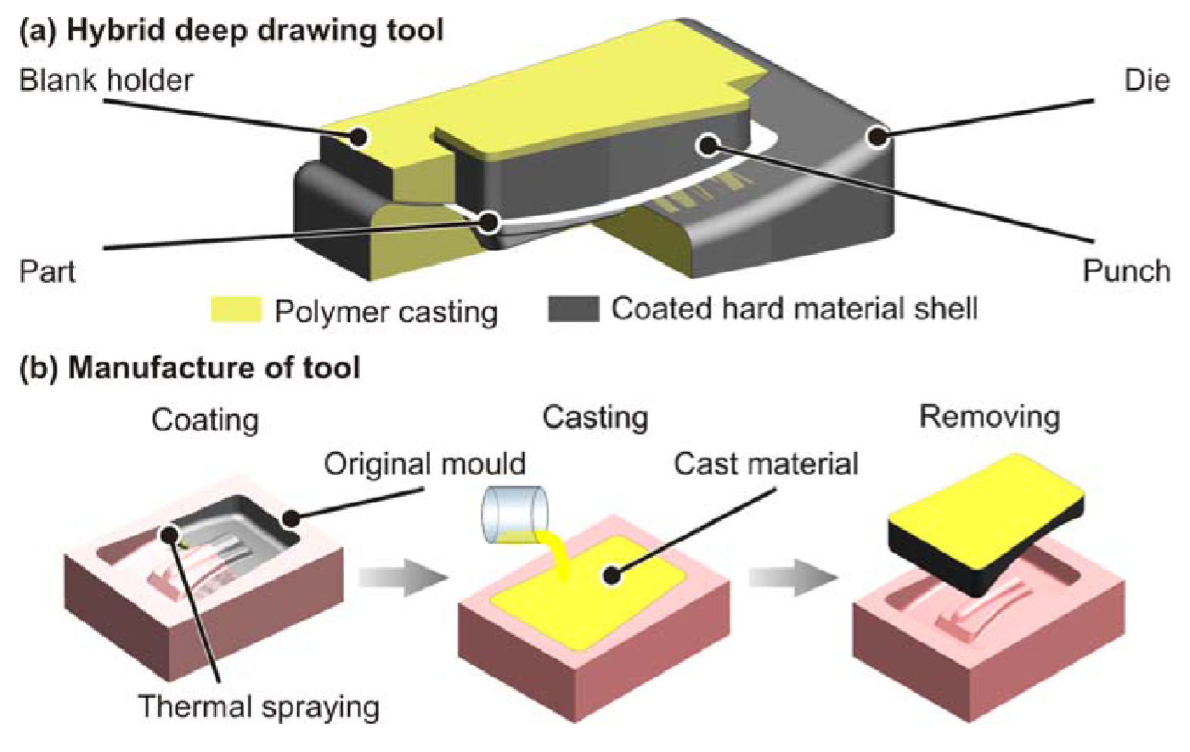
The condition of the surface layer of the tool determines its operational features, such as durability and reliability [3]. Under the conditions of high loads and plastic deformations of the surface layer of the workpiece material, the lubricant does not sufficiently separate the rubbing surfaces that remain in metallic contact with the summits of the surface asperities [4]. Wear resulting from the mechanical impact of rubbing materials is a phenomenon that makes it difficult to obtain components of the required quality, especially in the punching process [5]. The uncontrolled wear of tools reduces the quality of manufactured elements and increases the total cost of production [6]. The tool material should have wear resistance, high hardness and galling-resistance properties [7]. Conventionally, the basic tool materials are metals, mainly alloy steels. Steel is regarded as the most widely employed owing to the abundance of iron in the Earth’s crust, its high melting point and its variety of mechanical qualities [8]. However, composites [9,10], elastomers [11], polymers [12], wood [13] and laminated metals [14] can be used as tool material. Witulski et al. [15] developed wear-resistant deep drawing tools made of coated polymers (Figure 1). They used reinforcement fabrics of carbon in border areas of the hybrid tool in order to reduce critical stresses, and consequently to establish safe levels in the polymer body. The main advantage of the hybrid tool is the more homogeneous contact and higher wear resistance compared to conventional polymer tools.
One advantage of the use of polymers when compared to steel dies is their low interfacial adhesion energy, which leads to a low coefficient of friction (COF) [16]. Two main processes that impact the wear of polymers are interfacial wear (adhesion) and cohesive wear (mainly abrasion) [17]. Polymeric tools are characterised by lower Hertzian contact pressures, leading to viscoelastic and sometimes plastic deformations, which occur at relatively low loads [18]. Geueke et al. [19] fabricated SMF tools that are structurally optimised and 3D-printed from bio-based polymers to reduce the overall effort in constructing a flexible SMF in small batch sizes. The deformation behaviour of the optimised tool has been investigated during a drawing operation using a fused deposition modelling die printed from polylactic acid. Slight permanent deformations are indicated along the drawing radii of all polymer-forming tools, caused by high contact stresses.
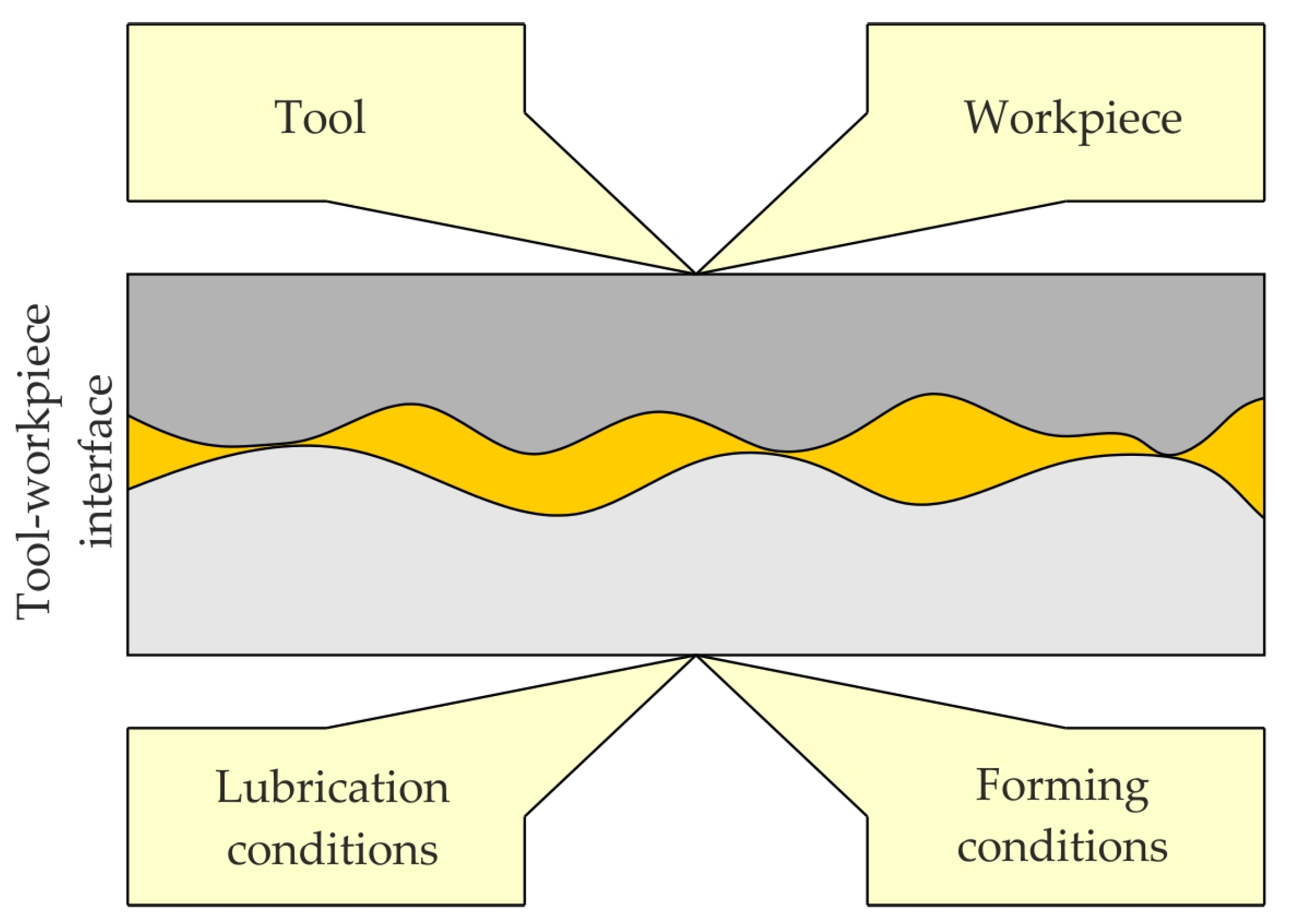
The phenomenon of friction occurring in SMF processes is a complex function of operating parameters [20], lubrication parameters [21], and the properties of the deformed material [22] and the tool [23] (Figure 2). The properties of the tribological system also include the kinematics of tool movement, the character of the loads (static, dynamic), the contact microgeometry [24] and the physicochemical phenomena on the contact surface [25]. Another property that influences friction in SMF is the strain-induced change in the surface topography of the sheet material. The surface morphology is important as it will change how the real contact area will affect the ability of the surface to carry lubricants [26].
The working parameters defining contact conditions include [27]:
- duration of contact;
- relative sliding speeds of bodies in contact;
- amount of the load;
- environmental parameters (humidity, temperature).
The characteristics of the deformed material and the tool include [28]:
- mechanical properties—yield stress, tensile strength, hardness;
- thermal expansion of material;
- properties of the surface layer of the deformed material—hardness, chemical composition of protective coating, surface roughness;
- properties of the surface layer of the tool—hardness, chemical composition of protective coating, surface roughness, delamination resistance;
- geometry of contact.
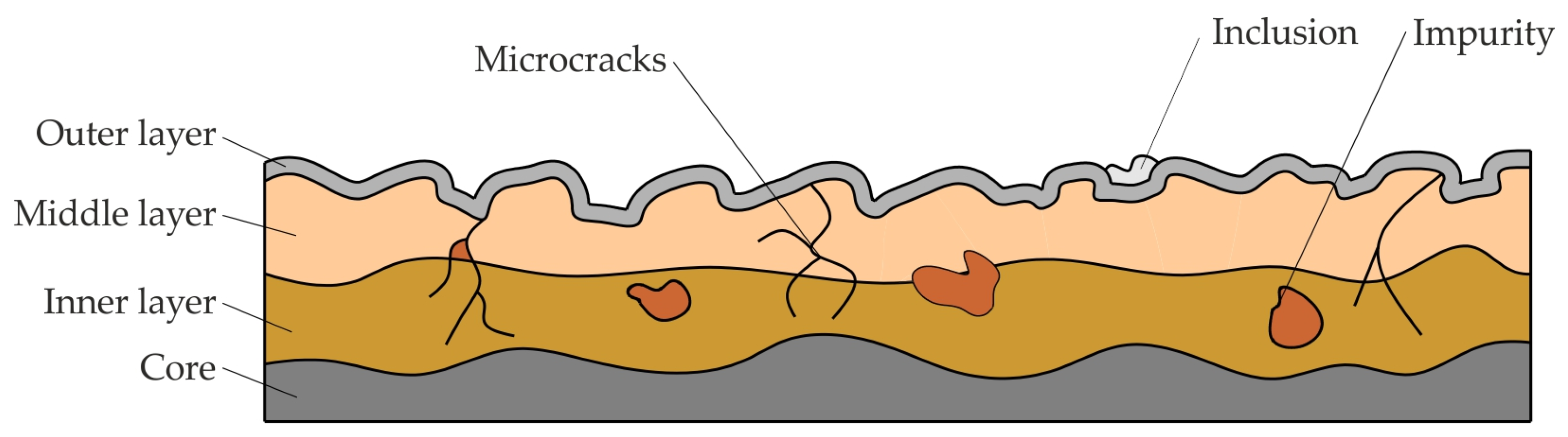
The model of the surface layer of the tool and workpiece is characterised by several properties that determine the occurrence and participation of individual wear mechanisms (Figure 3).
Owing to the subjection of different areas of the tool to nominal pressures and friction conditions, many tests were developed to simulate friction conditions only in selected places of the formed sheet, i.e., strip drawing test [30], a bending under tension test [31] and a draw bead test [32,33].
The operating conditions of tools for plastic working depend primarily on the temperature [34], the values of the transferred pressures [28] and the method of loading [5]. Tool wear is also activated by strain-induced surface changes in sheet metal forming [35]. Ensuring the required tool life is associated with the need to ensure the appropriate quality of the tool material and its heat treatment [35]. The correct selection of the material and heat treatment should be preceded by a thorough analysis of the mechanisms of wear and damage, and a determination of the boundary conditions of the tool’s operation [36].
An analysis of the literature shows that in recent years, much effort has been made to improve the friction conditions of the tools used mainly in machining processes. Meanwhile, the friction conditions of the tool used in SMF processes occupy much less of the researchers’ attention. This article presents the characteristics of tool wear mechanisms used in SMF. The possibilities of increasing the durability of tools by applying coatings produced by laser techniques, chemical vapour deposition (CVD) and physical vapour deposition (PVD) are discussed. Ways to improve lubrication conditions using self-lubricating coatings and surface-texturing are also presented.
2. Tool Wear in SMF
2.1. Wear Mechanisms
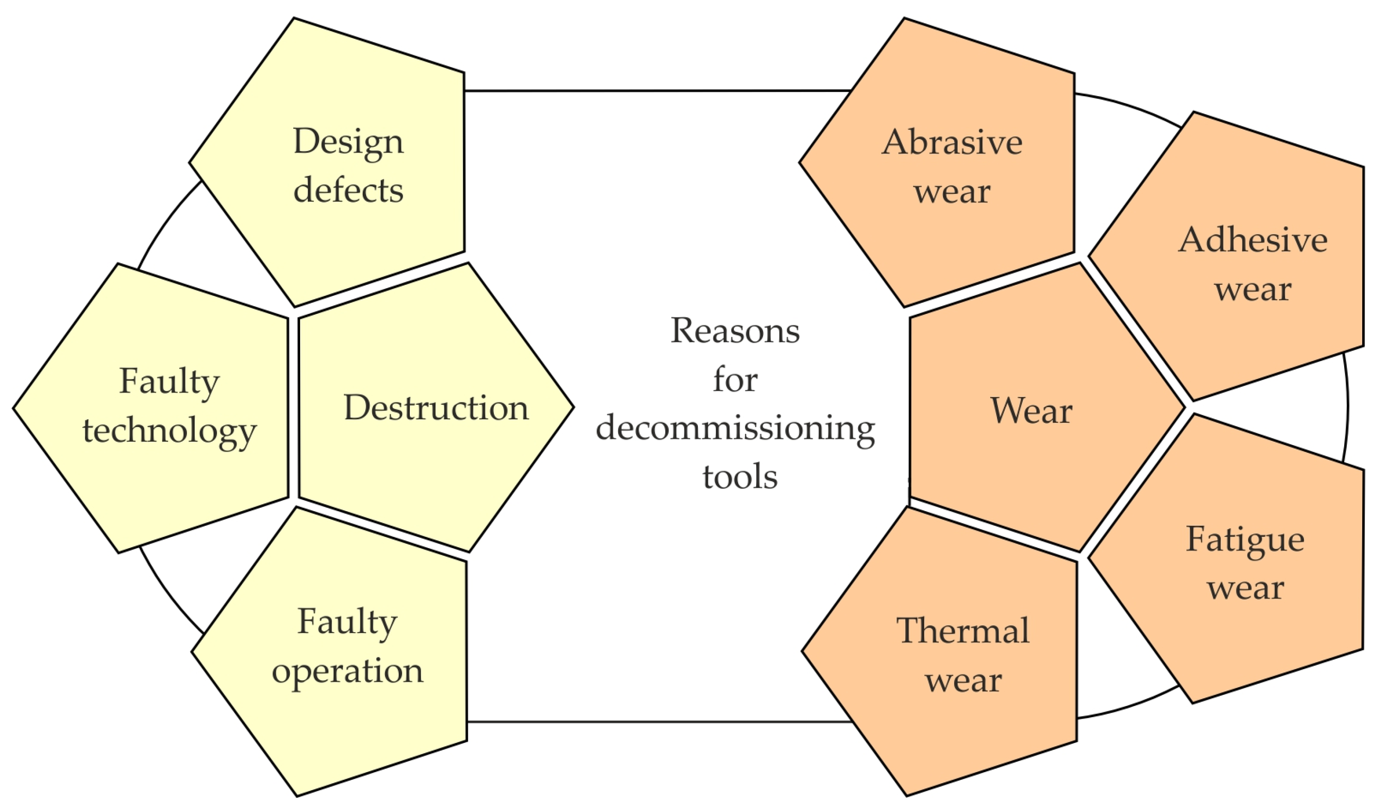
The wear process of tools for SMF, which are subjected to high mechanical- and friction-wear loads, is a complex phenomenon [37]. The process of tool wearing consists of corrosion, oxidation and mechanical and thermal fatigue. The improper design of tools can be a source of stress accumulation, which under the influence of dynamic loads is a source of cracks. Another parameter determining tool wear is the inappropriate selection of the material (insufficient hardness and, in the case of tools for hot SMF, low resistance to high temperature) [38]. Under conditions of high resistance to friction, the stress state and elevated temperature may cause unfavourable microstructural changes in the tool material, accelerating the wear process [39]. The basic types of wear include abrasive, adhesive, fatigue and thermal wear (Figure 4) [40].
Dobrzański and Dobrzańska-Danikiewicz [41] divided the processes of the mechanical wear of tools during operation in a more refined way, into pitting, spalling, adhesive wear, fretting, abrasive wear, scuffing, tribo-oxidation, Rebinder effect-induced wear, corrosion wear, erosive wear, cavitation wear, thermal wear, diffusion wear and ablative wear.
Adhesive wear occurs at low relative sliding speeds of the rubbing bodies, and is intensified by high unit pressures and an increase in speed relative to the rubbing bodies [42]. The mechanism can lead to the formation of cracks in the surface layer of the tool, intensifying the wear of its working surface. With this type of wear, the rubbing surfaces approach each other at the distance of the action of molecular forces, which leads to the formation of local friction joints. This phenomenon is accompanied by strong oxidation and additional action by hard oxides on the mating surfaces [39].
Abrasive wear is a phenomenon that accompanies the friction process, and is defined as a set of phenomena occurring in the contact areas of two rubbing surfaces leading to adhesive wear (galling) [43]. According to the ASTM G40 [44] standard, galling is defined as “a form of surface damage arising between sliding solids and distinguished by macroscopic roughening and creation of protrusions above the original surface”. The influence of the gliding speed and contact pressure on the abrasive and adhesive wear of forming tools (EN-GJS-700-2L) in the strip drawing test was studied by Groche et al. [45]. A significant influence of the gliding speed and the contact pressure on the mechanisms of wear appearing was found. The final stage of the galling process includes the coarse scratching of the sheets by lumps of material adhering on the metal forming the tool’s surface [46]. Contact pressure has a primary effect on the amount of abrasive wear. Hard particles separated from the surface of the tool can act as an abrasive material in contact with the workpiece with a much lower hardness. According to Berkowski [39], abrasive wear occurs at sliding speeds and pressures causing only a slight increase in the temperature of the tools, i.e., in conditions of not very intense friction. Abrasive wear is a phenomenon typical of the punching process. The abrasive wear of SMF tools occurs mainly as a result of loose material particles resulting from the oxidation of wear products and particles fixed in cooperating surfaces [41]. One type of abrasive–adhesive wear is scuffing, which involves the sticking and subsequent tearing of friction joints of the summits of surface asperities in micro-areas of contact [47]. There are numerous empirically observed relationships in the literature, which describes both adhesive and abrasive surface wear in sliding contact. These include relationships developed by Archard [48], Bayer [49] and Rhee [50]. Most SMF operations are not steady-state wear processes. As such, the most common—the Archard model for adhesive wear—is not applicable to predicting wear in SMF [51].
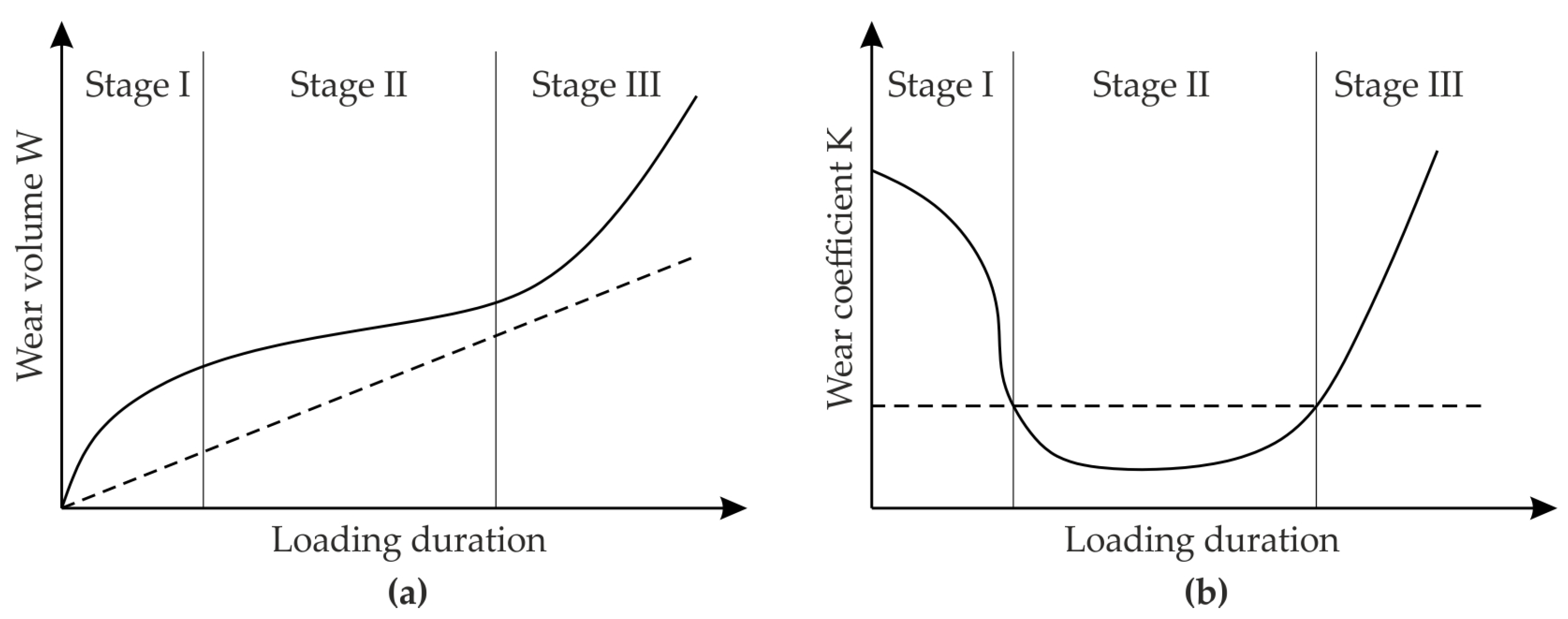
According to Ersoy-Nürnberg et al. [52], the wear process can be divided into three stages (Figure 5), in which wear volume W and wear coefficient K change differently. A typical wear curve shows three ranges: running-in (I in Figure 5a), normal wear (II in Figure 5a), and accelerated wear (III in Figure 5a). If a reconditioning of the tool is envisaged, the forming process should be stopped at the end of the normal wear range. Exceeding the stabilised range of normal wear, which does not yet cause changes in the dimensions and shape of the product, may lead to a rapid accumulation of various wear mechanisms. In zones II and III, the wear coefficient shows changes of a similar nature (Figure 5b) to that of the wear volume, except that it decreases sharply at stage I.
Spalling occurs under lubricated conditions, and is manifested by the formation of pits where the lubricant can enter. The pressure of the tool on the deformed material increases the pressure in the pits and their further chipping. Fatigue spalling is a mechanism similar to chipping, and entails the formation of subsurface micro-cracks, caused by cyclical loads on the tool surface, which grow and “come out” to the surface layer, creating craters [38]. The decrease in surface energy density and surface tension at the solid phase boundary as a result of lubricant adsorption is attributed to the Rebinder effect. The friction process stimulates the development of fatigue cracks as a result of the intermolecular forces of the lubricant and the formation of boundary layers [41].
Thermo-mechanical fatigue is the result of the action of cyclic mechanical stresses under high temperature conditions. Heat-activated processes cause a reduction in the strength properties of the tool as a result of, among other things, the recrystallisation of the tool material and the coagulation of carbides. Regarding sheet metal forming processes, the occurrence of this type of fatigue is mainly associated with tools used for rotary forming carried out at elevated temperatures.
Many studies have investigated the fault diagnosis or condition monitoring of stamping tools using a variety of methods, employing force sensors, acceleration sensors, strain measurement, audio emissions [53], acoustic emissions [54], data-based monitoring approaches [55], image-based tool wear classification [56], artificial neural networks and data-driven monitoring methods [57].
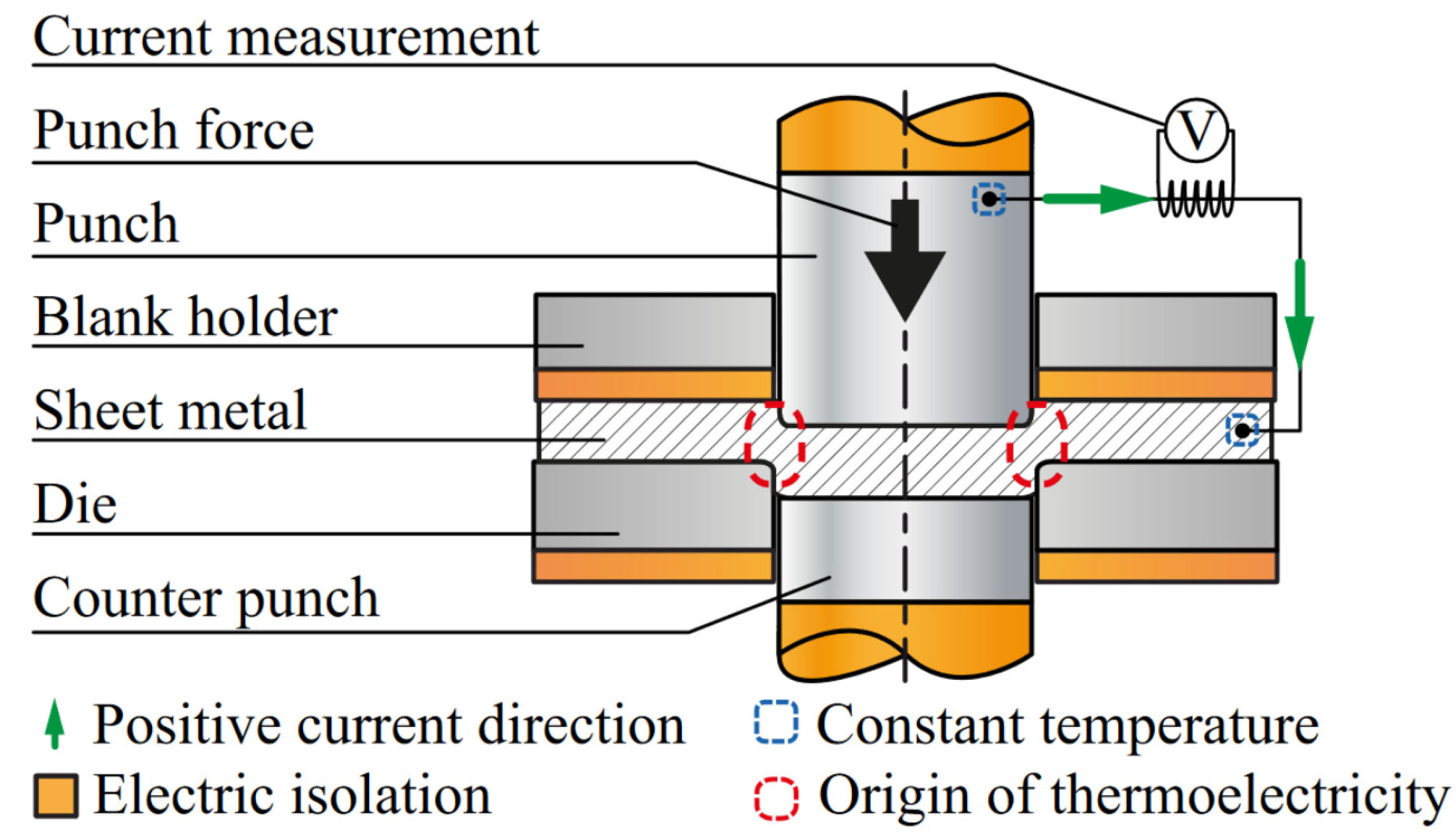
Tröber et al. [58] investigated the influence of Seebeck coefficients on adhesive tool wear during the blanking process. They developed a concept (Figure 6) for the measurement of thermoelectric currents and the prediction of tool wear. It was found that microscopic processes influenced by thermoelectricity play an important role in the formation of adhesive wear.
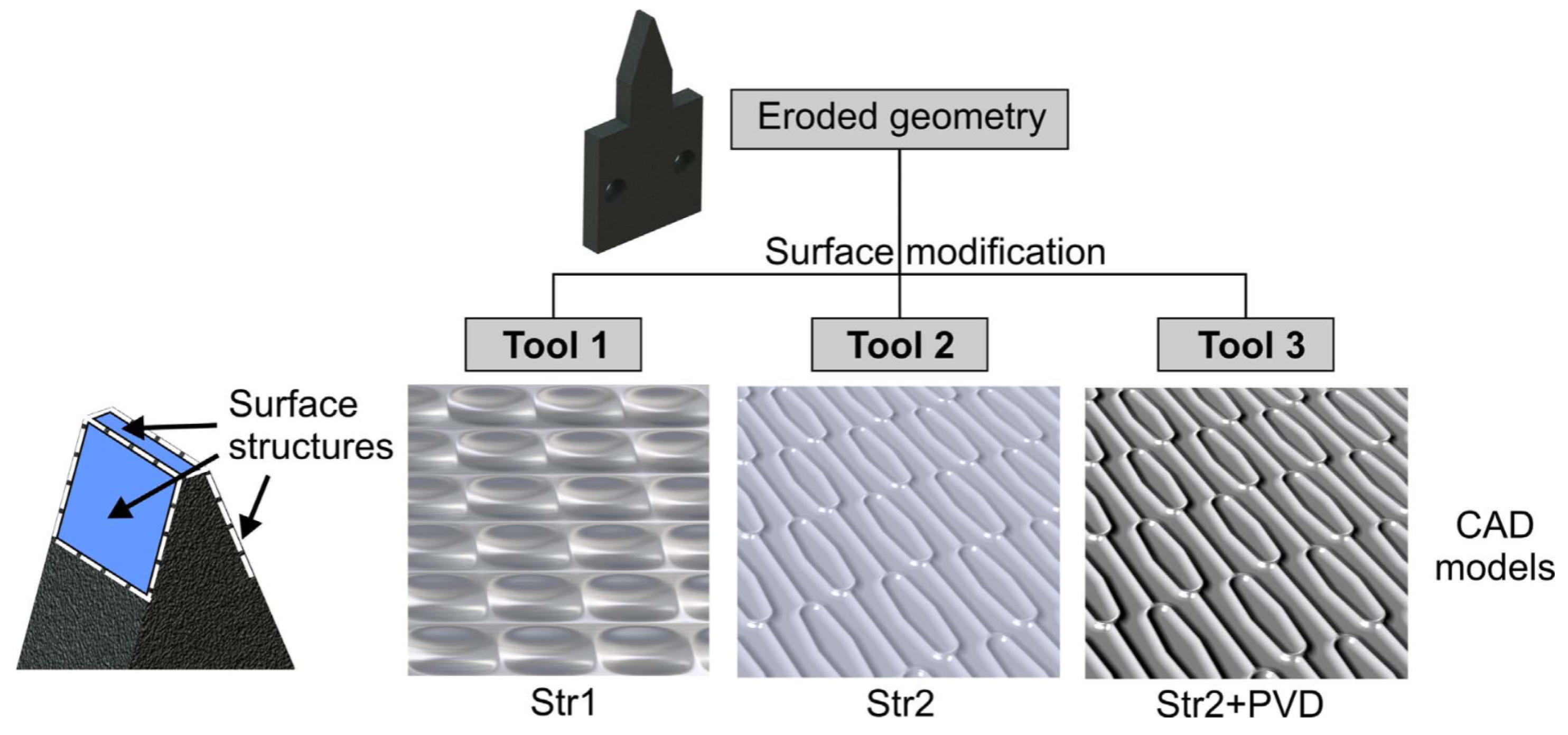
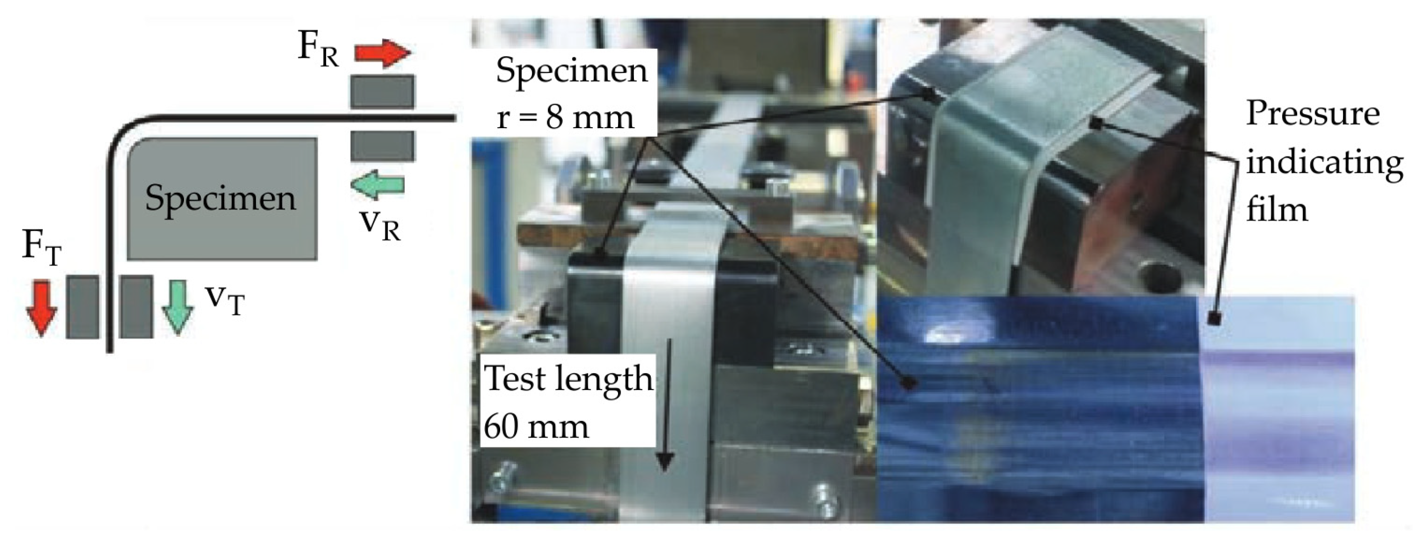
Groche et al. [59] developed a new experimental method for load-dependent wear prediction in SMF. A new characteristic wear variable, the specific wear force, was introduced. Reproducibility tests of different tribological systems indicate that the strip drawing test is a suitable wear test to analyse wear in SMF operations. Functional structures on the tool surfaces can influence the wear behaviour by the supply of lubricant pockets and reducing the contact area. Sieczkarek et al. [60] optimised tool surfaces for incremental forming processes. Various tool surface concepts and combinations (Figure 7) with CrAlN PVD coatings were analysed. It was found that surface structures combined with PVD coating provide a significant increase in the tool’s life (84%), compared with that of a non-modified tool. Schewe et al. [61] investigated wear characteristics simulated on metal forming tools with tailored bionic structure surfaces generated by micro-milling. The micro-structured surface showed quasi-isotropic structural resistance, wherein the sliding directions were perpendicular to the tool edge.
2.2. Causes of Tool Failure
The failure of a tool is most often the result of faulty design, faulty production technology or faulty operation. A tool material with insufficient hardness may cause permanent deformation of the forming surfaces [28]. Improperly conducted heat and/or thermo-chemical treatment is a source of microstructural changes and internal stresses in the material, which can also cause tool failure. The most frequently observed mechanisms of wear in tools used for cold SMF are [62]: cracks in dies and punches, abrasive wear, and thermo-mechanical fatigue of working surfaces.
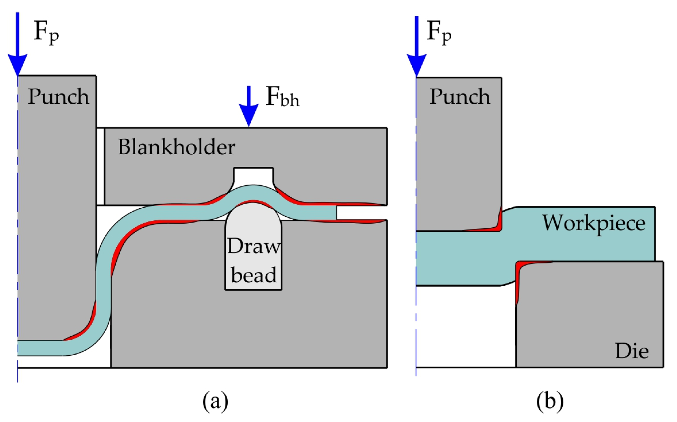
Stamping tool wear occurs mainly at the bottom of the rounded edge of the punch. The dies wear the most intensively on the drawing edge and under the blankholder, where there are very high circumferential compressive stresses, tending towards an increase in the thickness of the sheet metal (Figure 8a). The surfaces of the draw beads are also subject to high wear (Figure 8a). The edges of tools used in the punching process (Figure 8b) are exposed to abrasive and adhesive wear, resulting in the formation of scratches and galling. The nature of their wear varies during the individual phases of the punching process. In the phases of elastic and elastic–plastic deformations, the cutting edge is the most highly loaded, which can cause abrasive wear of this edge [38]. In the phase of cracking the workpiece material and removing the product from the processing zone, the work-hardened material of the workpiece moves along the side surface of the punch, increasing the intensity of adhesive wear in this zone.
The deterioration of the operational properties of hot forming tools is the result of the impact of many thermo-mechanically activated phenomena of various natures and intensities. In hot SMF processes, achieving the required performance properties involves considering the appropriate combination of properties of the surface layer and the core of the tool [28]. The most important processes include oxidation, the formation of a crack network caused by thermo-mechanical fatigue, corrosion in the presence of lubricants, and the formation of fatigue cracks caused by cyclic mechanical loads. Preheating the steel tools to a temperature of about 300 °C before starting work and cooling them during SMF have a beneficial effect on extending the durability of the tools. Statically loaded tools made of high-speed steel and hot work steel can be operated at a temperature of 300–400 °C, and tools subjected to cyclic loading can reach up to 500 °C [63]. The durability of SMF tools operating at a high temperature depends on the proper selection of operating conditions, including the use of appropriate cooling and lubricating agents.
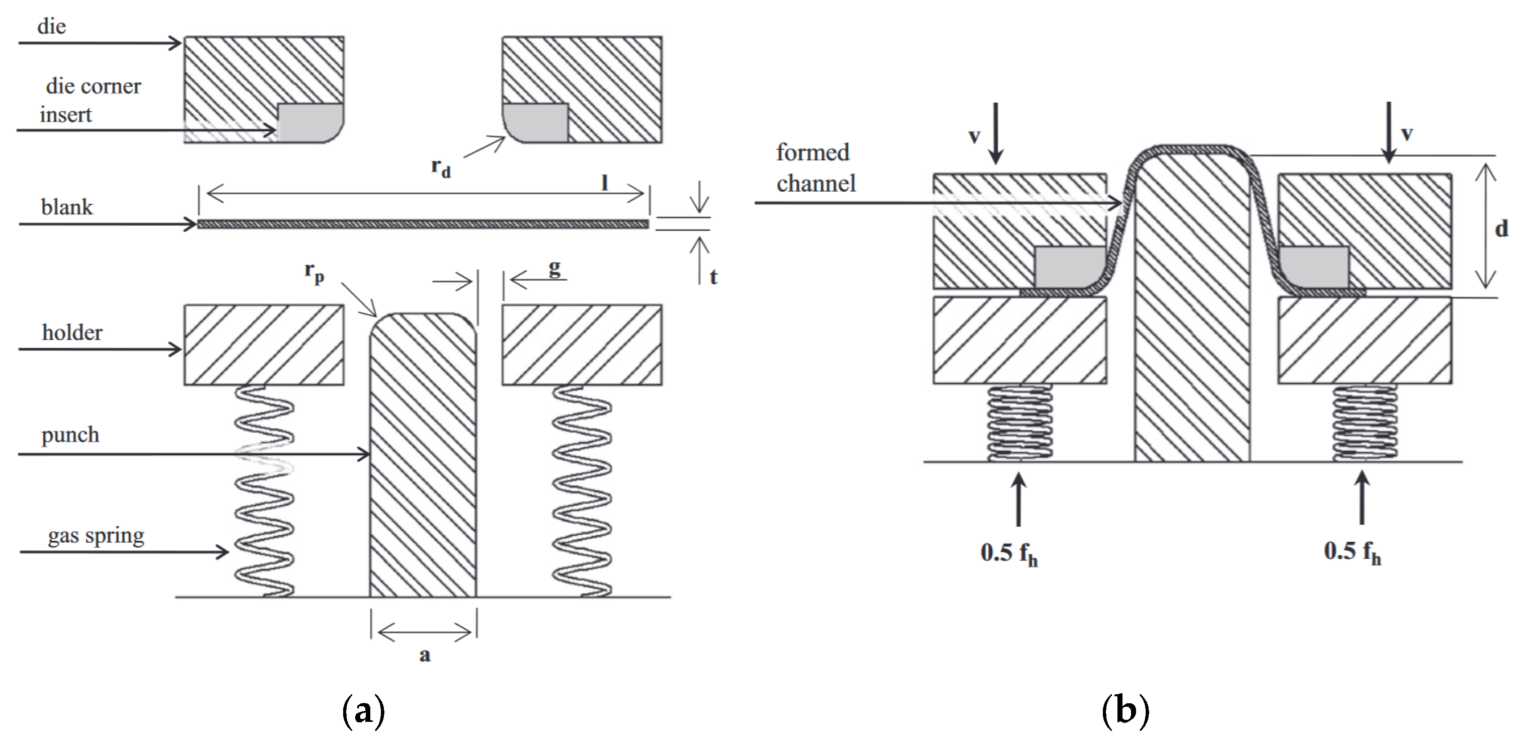
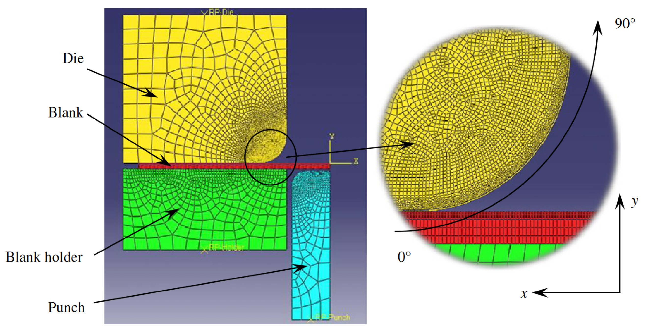
The die’s corner is the most loaded part of the stamping tool used in SMF operations, the profile shape of which should be optimised regarding lubrication conditions and unit pressures. Pereira et al. [64] developed a method of characterising the die profile shape and wear behaviour in SMF, based on a semi-industrial channel-forming process (Figure 9). Six AISI D2 tool steel die corner inserts were tested. It was found that small and localised profile shape changes of less than 15 mm from an ideal die corner radius profile can result in an approximate 90% reduction in tool life. Pereira et al. [65] studied the location, type and severity of wear that occurs over the die radius during a typical SMF process. It was concluded that the wear over the die radius consists of a combination of galling and ploughing mechanisms, and tool life is primarily dependent on the initial transient stage of the SMF. Behrens et al. [66] studied the wear behaviour of MoS2 layers in deep drawing processes on a test stand that ensures load conditions at the rounded edge of the die (Figure 10). The results indicate that the contact stress is concentrated at the inlet and the outlet of the stamping die. Wang and Masood [67] developed the numerical model (Figure 11) to investigate the effects of various die geometries on the tool wear distribution and the contact pressure in SMF. They considered different geometries of radius arc profiles (circular, flat elliptical, high elliptical), and the contact pressure distribution and wear volume along the radii were determined. It was found that the most favourable wear conditions were achieved by a combination of the circular and high elliptical curved profiles, and the die radius has a significant effect on the wear distribution.
3. Lubrication
The purpose of using a lubricant is to reduce the intensity of wear between the pair of rubbing bodies, leading to an increase in the durability of the tools [68,69]. In cold forming processes, in which the material is subject to large deformations, high sliding speeds and intense heat generation, the grease is also responsible for cooling the tools. Greases used in the processes of cold SMF should have high resistance to normal loads and exhibit anti-adhesive and anti-corrosion properties [70]. Greases used in plastic working at an elevated temperature should act as an insulator between rubbing surfaces, be resistant to high temperatures, and show stable physical and chemical properties in a wide temperature range [71].
Owing to their consistency, liquid lubricants (oils), emulsions (oil mists), solid lubricants and plastic lubricants are distinguished. Customised lubricants are available on the market for specific applications, e.g., for deep drawing, punching, rolling, etc. Based on their origin, lubricants are divided into natural (obtained from animal fats and vegetable oils), refined (obtained from petroleum) and synthetic varieties. The type of lubrication should be adjusted to the method of SMF (i.e., conventional SMF, incremental sheet forming) and to the grade of the formed sheet [72]. In the process of single point incremental forming, owing to the point contact of the tool with the sheet, there are more severe contact conditions than in conventional SMF [73]. Aluminium and titanium sheets show a much greater tendency towards galling compared to steel sheets [74,75].
Conventionally, in order to reduce friction and increase tool wear resistance, liquid lubricating oils are used [76]. Plastic greases that are colloidal solutions of solid densifiers in the liquid phase consist of a matrix, a thickening phase (10–25%) and fillers (1–15%) that improve operational properties [77]. Solid lubricants, called self-lubricants, can be used at low temperatures, as well as at high temperatures where liquid lubricant can solidify or vaporise. Solid lubricants are used in a very wide temperature range (from −200 to +1500 °C), at very high loads and in chemically active environments [78].
Graphite obtained from natural sources or by chemical synthesis is one of the stable allotropes of carbon, and crystallises in a hexagonal lattice with a lamellar structure. The large distance between the base planes and the oriented structure provides a good cleavage and ease of sliding in favoured directions. Graphite is used in severe friction conditions and retains its lubricating properties up to a temperature of about 400 °C [28].
In order to increase tool wear resistance, anti-wear coatings containing titanium and molybdenum disulphide are produced. The lamellar structure of molybdenum disulphide MoS2 consists of alternating layers of molybdenum and sulfur atoms. MoS2 belongs to the group of transition metal dichalcogenides and has a strongly anisotropic crystal structure. This facilitates the mutual movement of these layers and, under certain conditions, leads to a reduction in COF [79].
In the last two decades, much emphasis has been placed on ecological aspects. Sunflower [80], coconut [81], soybean [82], linseed [83], rapeseed [84], Karanja [85] and many other oils are considered potential bio-lubricants [86]. One approach to reducing friction under boundary lubrication conditions is the use of diluted solutions of saturated fatty acids (palmitic and stearic acids) in vegetable oils [87]. Vegetable-derived oils are environmentally friendly and an alternative to conventional lubricants, owing to their high load capacity, low COF, high flash point, low evaporation rates, excellent anti-wear properties, high viscosity index and non-toxicity [88]. Owing to their favourable mechanical properties, carbon nanotubes (CNTs) are used in various forms for tribological applications, including as additives to water-based lubricants [89] and oil [90]. The reduced COF and high wear resistance are associated with the formation of a film of amorphous carbon transferred from CNTs on the friction surface [91]. Various aspects of bio-lubricants, such as the tribological performance of bio-lubricants under various conditions, and the physicochemical and rheological properties of bio-lubricants and various nanoparticles used to enhance the performance of bio-lubricants, have been presented in review papers by Pawar et al. [92] and Uppar et al. [93].
The use of appropriate lubricants on tools with hard coatings with a metastable form of amorphous carbon DLC/TiAlN [94] makes it possible to reduce the COF at the contact between the die surface and the workpiece [95]. The presence of a mineral oil layer reduces the tensile stresses of the DLC/TiAlN coating surface during sliding, improving the wear resistance of the die surface even at high temperatures and high contact pressures. Kim et al. [96] showed that the use of wear-resistant tool coatings under conditions of boundary friction reduces heat generation at the contact between the die and the workpiece.
4. Protective Coatings for Tools
4.1. Methods of Constituting Surface Layers
The tool’s physico-mechanical properties have the greatest impact on the tool’s work efficiency, and the most effective way of shaping them is to use mechanical and physico-chemical strengthening, the application of wear-resistant coatings and comprehensive surface treatment [28]. Surface strengthening methods can be divided into four groups. The first group includes methods related to surface plastic deformation, called mechanical work hardening. The second group includes methods related to thermo-chemical treatment. The third group consists of electro-spark and ultrasonic strengthening methods, which are characterised by a level of unit energy up to 106 J/cm2. The fourth group includes methods of physical strengthening (beam techniques), which are characterised by a high level of unit energy of 108 J/cm2.
The individual characteristics of metal forming processes are imposed by the shape of the final product and the properties of the workpiece. The problem of designing and manufacturing tools for a specific application is related to the development of a complex material that would have high resistance to temperature tempering, high mechanical strength and sufficient ductility in its core [38]. An effective way to ensure the operational properties of metal forming tools is to produce surface layers. The basic groupings of these methods are as follows [97]:
- mechanical methods—burnishing, shot peening, hammering, cold working;
- physical methods—vapour deposition by sputtering, spraying and evaporation techniques, ion implantation;
- thermal methods—heat treatment (hardening, annealing, tempering), surfacing;
- thermal–mechanical methods—gas and plasma spraying, spray deposition, hot plastic working;
- thermal–chemical methods—diffusion alloying with non-metallic elements (nitriding, carburising, boronisation, carbonitriding), diffusion alloying with metallic elements (tin plating, aluminising, galvanising), laser and electron-beam alloying;
- chemical and electrochemical methods—conversion deposition of phosphate, oxide and chromate coatings, electrolytic deposition of metals or alloys (i.e., nickel plating, chrome plating, zinc plating), plating and chemical or electrolytic etching.
By selecting the parameters of the surface hardening process, layers of the required hardness and depth are obtained. Electron hardening is one of the technological operations that enable the achievement of high hardness in the surface layer of the metal while maintaining the plastic properties of the core. The surface layer obtained as a result of laser remelting or alloying with carbide powders of hot-work tool steel is characterised by higher mechanical and functional properties compared with steel that is subjected to conventional heat treatment [98]. The tendency of a surface layer subjected to laser treatment to crack can be eliminated by applying to it gradient concentrations of the alloying component [99].
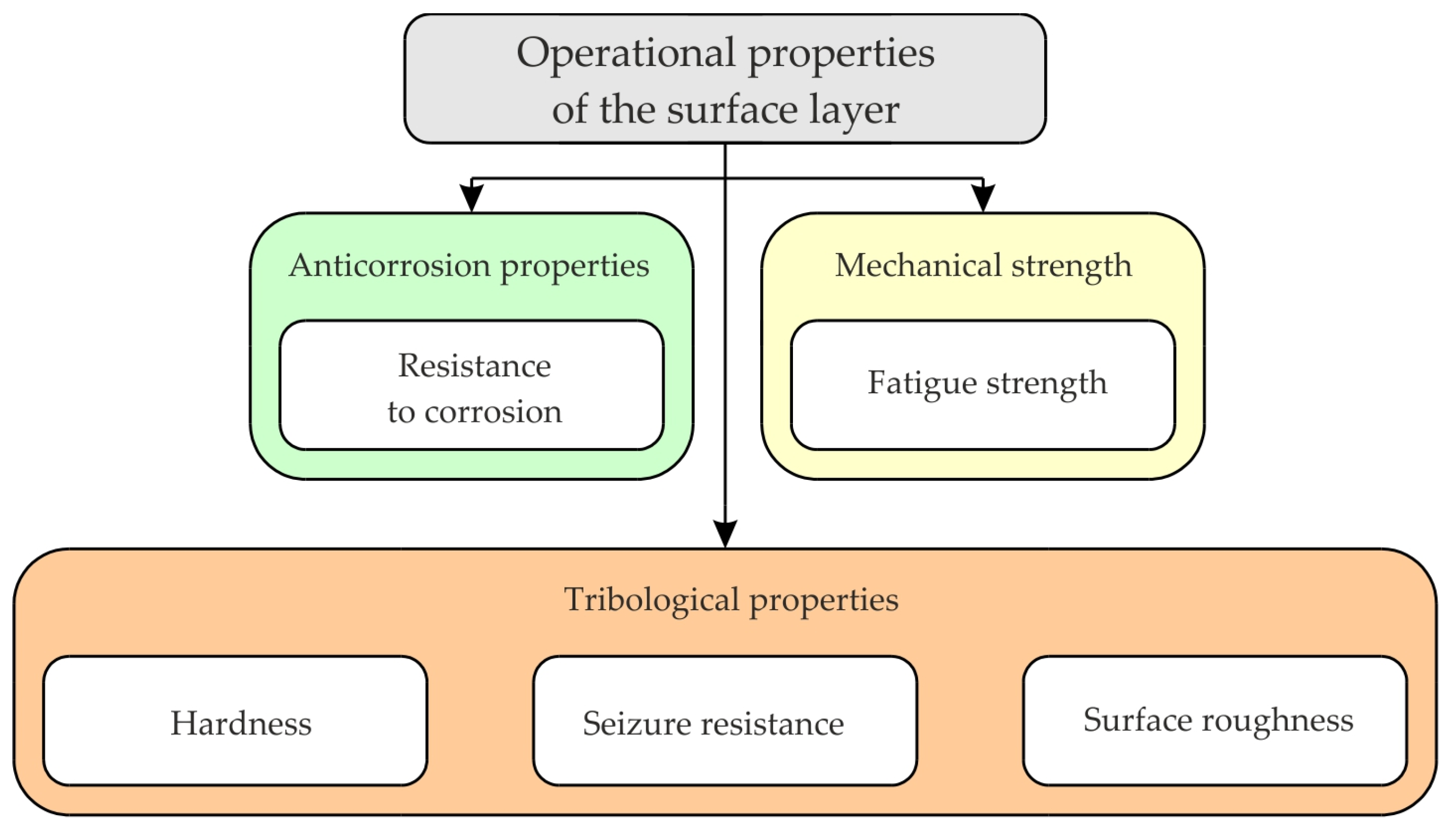
The beneficial effect of the work hardening of metals is used to increase the strength of the surface layer of tools (to a depth of several millimetres) in the following processes: vibratory and abrasive treatment, explosive hardening, burnishing and shot blasting. The hybrid laser–mechanical processing (laser texturing combined with burnishing) method guarantees a reduction in surface roughness, work hardening and the introduction of compressive residual stresses (type I, II and III) to the surface layer. In this way, favourable operational properties of the surface layer are ensured, such as increased contact stiffness, and resistance to erosive and abrasive wear. The efficiency of the plastic forming tool depends primarily on the operational properties of the surface layer, in particular its hardness and its resistance to tribological, thermal, fatigue and abrasive wear (Figure 12).
The physical shaping of the surface layer’s properties to a depth of several tens of micrometres involves the deposition of coatings connected to the substrate by diffusion or adhesion forces. Chemical and electrochemical methods involve the direct deposition of a metallic or non-metallic material on the surface of the tool, with a thickness of several micrometres to several millimetres, for example in the electroplating process. Thermal methods rely on the impact of the appropriate temperature on the surface layer of the tool in order to cause microstructural changes that change the strength characteristics [28].
4.2. High-Energy Techniques
High-energy techniques use different types of energy carriers to change the properties of surface layers: ions, electrons or photons. Interest in these methods of treatment results mainly from the possibility of achieving a high concentration of energy and directing it precisely to selected areas of the surface. In the case of electron beams, the power concentration reaches 1013 W/m2. Electron beams reach a maximum power of several hundred kilowatts, while laser beams reach a maximum of several kilowatts. In addition, the efficiency of energy transfer in the case of an electron beam usually exceeds 75%, while for a laser beam it is often lower than 10%. The energy of the laser beam is converted into heat only on the surface of the material, and the energy of the electron beam causes heating of the near-surface layer.
The aim of the implantation is to obtain a layer with a thickness of usually around 0.2 to 0.3 μm, characterised by high hardness and very good resistance to abrasive wear. It is also possible to obtain layers with improved lubricating properties and increased fatigue strength. Ion implantation is accompanied by an increase in the surface temperature of the implanted material, which depends primarily on the energy of the ions. Metals and alloys can be implanted with non-metallic elements (e.g., nitrogen, carbon) or metals (e.g., titanium, boron). Increasing the abrasion resistance can be achieved by implanting the metal surface with ions of nitrogen, titanium, carbon, boron, tantalum, molybdenum, yttrium, tin or silicon [100]. The advantages of ion implantation include the ability to obtain concentrations of dopants exceeding their solubility in the doped material, and the ability to precisely control the concentration and distribution of dopants. The disadvantages of this technique include the inability to implant materials with complex spatial shapes, and the limited thickness of the implanted layers.
Laser surface heat treatment (surfacing, alloying, remelting) is used mainly to increase the durability of tools and responsible structural elements [101]. The hardness of the surface layer alloyed with carbide powders increases with the increased laser power used for alloying [102]. The surface layer of the alloy steel obtained as a result of laser remelting or alloying with carbide powders is characterised by higher mechanical and functional properties compared to steel subjected to conventional heat treatment. In the remelted zone, a complex state of stress occurs owing to the change in the volume of the material resulting from thermal effects and phase transformations [103]. The remelted layer is characterised by increased hardness and abrasion and corrosion resistance. The disadvantage of laser processing is the uneven distribution of power in the laser beam.
Gradient layers provide high wear resistance and high heat resistance. In recent years, hybrid methods have gained great attention, and been used in the initial application of a layer of carbide-forming metal on the tool surface, followed by saturation of the surface with nitrogen, carbon, or both of these elements at the same time. In this way, hard, wear-resistant carbonitride layers are obtained.
Laser surface treatment techniques are used to modify the surface of bending tools and stamping tools, where, in addition to high hardness, low surface roughness is required. Cold work tool steel X153CrMoV12 used for tools for deep drawing [104] is commonly laser-processed. Surface-modified materials are used for tools for the following lubricant-free forming processes: cold massive forming [105], deep drawing [106,107] and rotary swaging [108,109].
4.3. Coatings Produced in PVD and CVD Processes
To improve the durability of tools operating under high pressure and high temperature, the best results are provided by hybrid methods of surface layer modification, which combine methods of heat treatment (usually nitriding) and one of the PVD or CVD techniques [110]. PVD and CVD wear-protection layers provide extremely adhesive hard material layers (nitride or carbide of Ti, Cr, Al and Zr) that are characterised by low COFs and high oxidation resistance (up to around 900 °C) and high hardness (2000–4000 HV0.05) [111,112]. The main task of the nitrided layer is to increase the hardness and resistance of the substrate to plastic deformation, so as to protect the PVD or CVD coating against loss of cohesion with the substrate. CVD and PVD techniques differ primarily in process parameters, temperature and time, as well as layer formation mechanisms, physical reactions in the case of the PVD technique, as well as chemical phenomena in relation to the CVD technique.
In the PVD method, layers are deposited by the crystallisation of plasma vapours using physical phenomena such as the evaporation of metals or alloys, cathodic sputtering in a vacuum, and ionisation. These vapours are deposited on a cold or heated substrate. Coatings obtained by the PVD method usually have a thickness of 3–5 μm and a hardness of 2000–3500 HV [113]. PVD methods are used to cover the surfaces of tools with titanium nitride TiN (less often with titanium carbide TiC) in order to achieve an exponential increase in their durability. The service life of tools coated using PVD methods is several times longer life than that of tools manufactured conventionally, without protective coatings [114]. Coatings produced using the PVD process can be divided into simple (consisting of one material, metal or phase) and multiphase, multilayer, multicomponent, gradient and composite coatings [115]. The most important PVD techniques used to apply coatings on tools include [100]: activated reactive evaporation, bias activated reactive evaporation, cathodic arc deposition, cathodic arc evaporation, hot hollow cathode deposition, ionised cluster beam, the pulse plasma method, reactive arc ion plating and reactive ion plating, reactive magnetron sputtering, and thermionic arc evaporation.
The CVD method entails creating hard layers of carbides or nitrides with carbide-forming elements. The process can be carried out at atmospheric pressure in a gaseous atmosphere containing chemical vapours of the diffusing metal (usually in the form of a halide) and hydrocarbons, nitrogen, hydrogen or an inert gas. Heat-activated components of the atmosphere are released on the surface as a result of the catalysed reaction. The second component of the layer may come from the substrate (e.g., carbon) or from the atmosphere (nitrogen). A limitation of the application of the CVD process is the high temperature necessary for the course of chemical reactions, which is why plasma-assisted CVD was developed, as it allows the process temperature [116] to be reduced. In the processes of chemical vapour layer deposition, atmospheric components can be activated by heat or plasma. Heat-activated processes can be carried out via atmospheric-pressure CVD [117] and low-pressure CVD [118]. PVD and CVD methods enable the formation of hard layers, primarily nitrides and carbides, as well as borides and some metal oxides on forming tools. Dos Santos et al. [119] list the processes of deposition of thin multilayer coatings, of which the following are dominant: chemical deposition of nanometric surface layers by the CVD method, pulsed laser deposition and molecular beam epitaxy.
Tillman and Stangier [120] introduced PVD coating, as well as bionic-inspired surface structures, for adapting the tribological conditions for sheet-bulk metal formation. CVD and PVD coatings have been successfully used on fabrication stamping tools operated in high-load applications [121,122]. The PVD–CrN–coating tools are used to form aluminium sheets. WC/C coating distinctly reduces the build-up of aluminium on the tool surface [123]. CVD multilayer coating (TiC + TiN) has been used in stamping or coining tools [123].
PVD coatings used on the surface of punches, dies, and forming tools have an advantage over CVD coatings. The heat treatment of PVD coated tools takes place at a lower temperature not exceeding the austenitisation temperature of some base materials. The high hardness of superlattice coatings (50 GPa) with thickness 1–20 nm [124] is beneficial for highly loaded tools used in blanking/punching operations [125]. TiN-coated tools used for punching applications are characterised by a hardness of 17 to 35 GPa for PVD or plasma-assisted CVD.
4.4. Functional Coatings
The lifetime of a forming tool can be increased by surface functionalisation. Multiphase coatings are produced under conditions of high deposition rates via the ability to control the kinetics of crystallisation. If a mixture of phases is formed under equilibrium conditions, then as a result of annealing under certain conditions, the dispersion of small crystals in the amorphous matrix or dispersion of interphase boundaries in the crystalline matrix occurs [126].
The development of wear-resistant nanostructured coatings is possible thanks to their structures being shaped on the micro and nano scale. The main advantage of these coatings is their very high durability. When developing tribological coatings, it is necessary to optimise the hardness to obtain its highest possible value, and manipulate the Young’s modulus to obtain its lowest possible value [28]. Gradient or complex gradient and multilayer nanostructured coatings allow for the formation of various properties of coatings at the interface between the substrate and the coating. Superstructural coatings show particularly advantageous properties among nanostructured coatings [127]. In the case of such structures, an increase in hardness of up to 300% is observed in relation to the hardness of the individual nitride phases, which can be explained by the inhibition of dislocations at the phase boundary with different shear moduli [128]. Czechowski and Wrońska [129] proved that among the new protective coatings, multilayer nitride coatings are dominant (Table 1), and their properties are adapted to specific applications by special technologies within the PVD process.
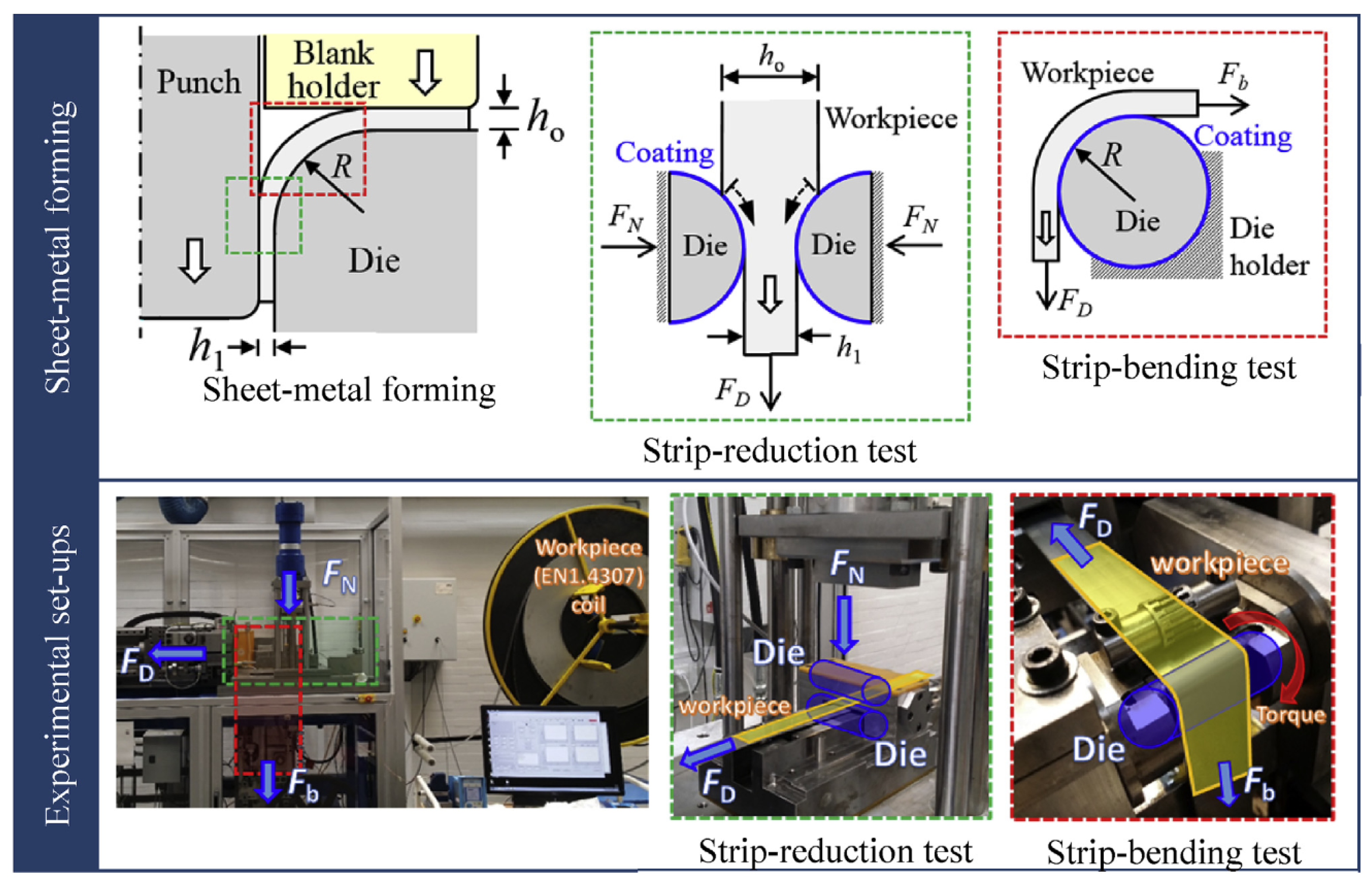
Table 2 shows selected properties of the coatings used on advanced high-strength steel (AHSS) stamping dies. Diamond-like carbon (DLC) and TiAlCrCN coatings are practically insensitive to temperature increases up to 400 °C. DLC coatings have been developed in order to improve the tribological performances of the sheet/die system, enabling dry or nearly dry forming operations [144]. Sulaiman et al. [18] investigated the influence of DLC/TiAlN-coated die surfaces in SMF under dry and oil-lubricated conditions. Single-layer DLC, single-layer TiAlN, double-layer DLC/TiAlN and multilayer DLC coating films deposited onto Vanadis tool steel substrates were subjected to strip reduction tests and strip bending tests against stainless steel sheet metal (Figure 13). DLC/TiAlN exhibited a high potential for use as a protective coating under all test conditions. The DLC/TiAlN coating protected the die surface from the onset of adhesion wear, even under dry friction conditions, as a result of a large amount of titanium in the interlayer TiAlN. The TiAlN coating has been investigated as a protective layer for use in forming dies as an alternative to other industrial PVD hard coatings, such as TiC, AlCrN and TiCN [145].
Taube [146] and Murakawa et al. [147,148] used DLC-coated dies in the deep drawing of aluminium- and zinc-plated steel sheets. The DLC coating showed satisfactory performance under dry forming and oil-lubricated conditions. Krachenfels et al. [149] deposited a DLC coating onto the surfaces of stamping tools for dry deep drawing.

Table 2.
Selected properties of coatings used on AHSS dies (prepared based on [150]).
Table 2.
Selected properties of coatings used on AHSS dies (prepared based on [150]).
| Coating | Ra, μm | Hardness, GPa | |
|---|---|---|---|
| Ambient Temperature | 400 °C | ||
| TiAlN | 0.03 | 33.5 | 30.5 |
| AlTiCrN | 0.05 | 18 | 16.4 |
| TiAlCrCN | 0.07 | 28 | 27.6 |
| DLC | 0.03 | 28 | 27.6 |
| AlTiCrN+CN | 0.03 | 29 | 27.2 |
| AlCrSiN+CN | 0.02 | 27 | 25.8 |
| AlTiCrN | 0.04 | 38 | 29 |
Coatings consisting of “heat-resistant” elements (Al, Cr, Ti) in combination with elements (C, N) with a low COF provide high protection against wear, and show resistance to high temperatures [150]. Under conditions of sliding movement, the wear of the TiAlN coating at room temperature was greater than that of the AlTiN coating, while at 600 °C, the differences disappeared. Good oxidation resistance and a good load-carrying capacity are the most important characteristics of TiAlN-coated tools [151]. The TiAlN-coated surface’s hardness is approximately 3400–3600 HV [152]. Moreover, The TiAlN coating possesses better tribological properties than those of TiN, AlTiN and CrAlN coatings [153].
Nanotechnology techniques include the processes of designing and manufacturing structures by controlling their shape and size on an atomic or molecular scale, showing at least one dimension on the nanometric scale, i.e., 10−9 m [154]. Coatings with a nanocrystalline structure showing increased corrosion resistance, hardness and abrasion resistance, obtained as a result of deposition of particles or atoms (by PVD and CVD techniques, and liquid phase deposition), are a group of nanostructured materials [155].
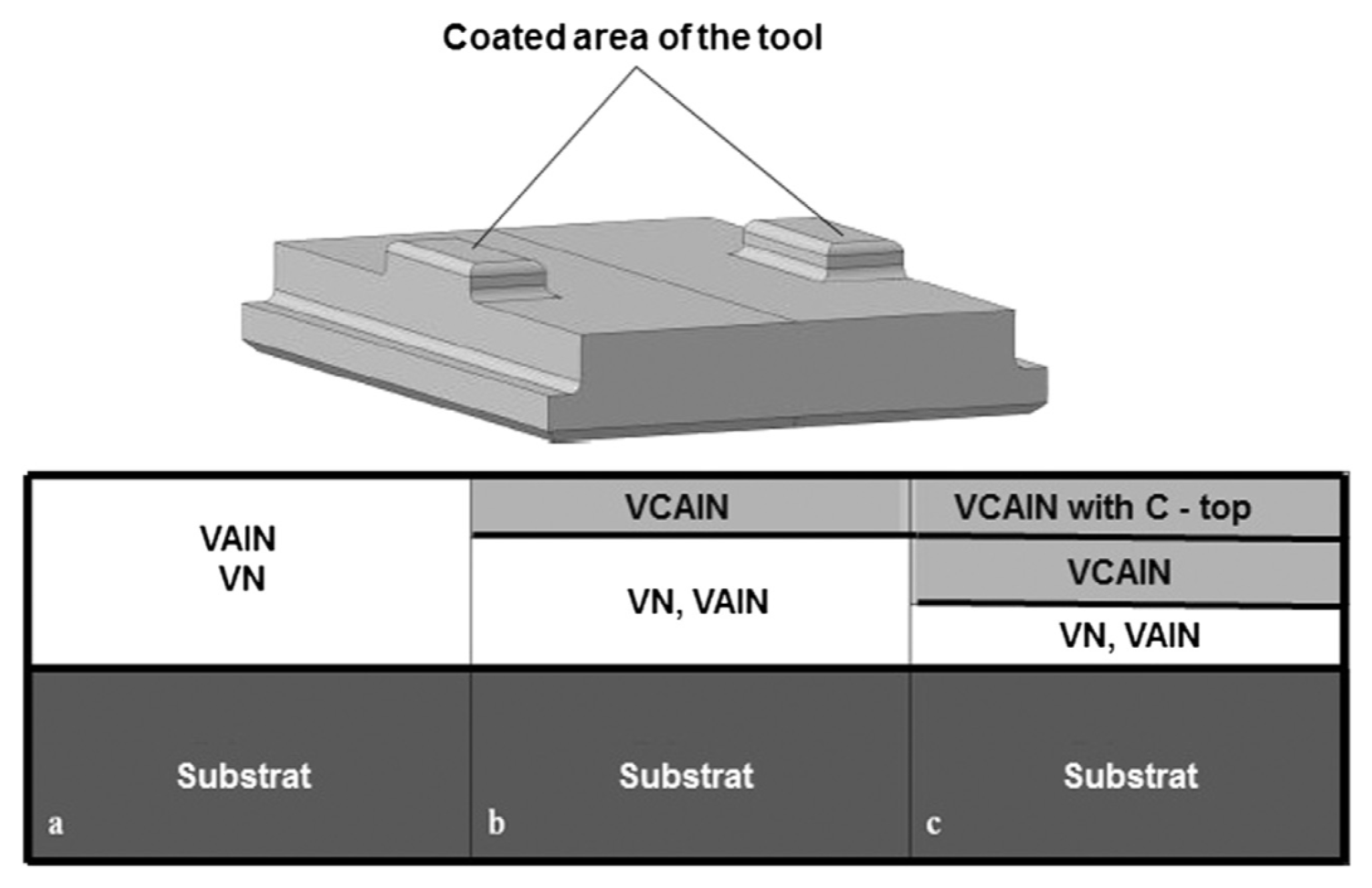
Becker [156] developed nanostructured composite coatings for forming tools: vanadium carbide aluminium nitride (VCAlN), vanadium aluminium nitride (VAlN), multilayer VAlN + VCAlN (double layer) and VAlN + VCAlN with a carbon-enriched top layer (Figure 14). Wear tests confirmed that the nanolaminates in the VCAlN system can be used in principle as tool coatings when forming materials without additional lubricant, or with a minimum quantity of lubricant.
5. Self-Lubricating Materials and Coatings
According to Płaza et al. [78], the term self-lubricating coating should be understood as “a mixture of a binder and lubricants, which, after being applied to the mating surfaces and then dried, forms a thermo- or chemically hardened coating characterised by a sufficiently low COF, then mutual movement of the rubbing surfaces is possible without the need for additional lubricants”. Self-lubricating coatings can be prepared for example by vapour deposition [157], magnetron sputtering [158], laser deposition [159] and powder metallurgy methods [160].
Originally, composites based on polymers with the addition of fillers in the form of fibres, powders (Figure 15) or liquids and additives that impart appropriate cohesive properties of the layer and adhesive properties of adhesion to the substrate were developed as self-lubricating materials. Fibrous fillers include glass, asbestos, aramid, carbon, nylon or polyester fibres [78]. Graphite, carbon and aramid fibres show very good tribological properties. Among the powder fillers, graphite, bronze, molybdenum disulfide and polytetrafluoroethylene (PTFE) are the leaders. The use of these lubricating coatings in hot plastic working is very limited owing to the occurrence of very high unit pressures and high temperatures. The wear of self-lubricating polymer composites is strongly dependent on the surface roughness and the orientation of their topography. Polymer composites with the addition of MoS2 in the form of nanopowders show significantly higher anti-wear and friction properties than other types of composite coatings. Resin coatings with the addition of MoS2 are used to produce tools for material processing; other types of composite coatings are used in non-maintenance kinematic nodes in the aerospace and space industries. For the same applications, Płaza et al. [78] proposed the production of two types of thick nanocomposite low-friction coatings based on amorphous carbon and MoS2, which were deposited by magnetron sputtering on Vanadis 23 steel substrates. As part of the Nanocoat [161] project, nanocomposite coatings were developed using the electrodeposition of cobalt–tungsten (Co-W) alloys impregnated with MoS2 and tungsten carbide (WC) with self-lubricating properties. Mitsuno et al. [162] presented the results of testing a new coating produced by implanting chlorine into a titanium nitride coating.
Fluorides, most often BaF2 and CaF2, provide favourable tribological properties above 500 °C due to the transition from the brittle phase to the ductile phase at this temperature. At temperatures below 500 °C, fluorides are brittle and do not effectively self-lubricate. Kotkowiak [163] produced self-lubricating technological surface layers containing solid lubricants in the form of calcium and barium fluorides, and their impact on wear resistance was determined. It was found that on the surface of the self-lubricating composites, layers of tribofilm of varying thicknesses were formed, which protected the surface of the sample and countersamples made of Inconel 625 nickel alloy against wear due to friction. Wang et al. [164] produced CaF2/Al2O3 composite coatings by laser cladding. The addition of calcium fluoride reduced the COF and increased resistance to wear, especially at the temperature of CaF2 transformation from the brittle phase to the plastic phase (a temperature of about 600 °C). Zhang et al. [165] produced a WS2-based coating with the addition of CaF2 by high-velocity oxygen fuel supersonic spraying. With the increase in temperature, the composite coatings showed better anti-wear properties, which may be related to the presence of the ductile CaF2 phase.
Adaptive tribological coatings provide self-lubricating properties not only by virtue of the presence of the individual components of each coating, but also by virtue of the presence of the products of chemical and physical reactions that occur under the influence of friction conditions [163]. Coatings consisting of ZnO/WS2 [166] and PbO/MoS2 [167] provide a lubricating effect in a wide temperature range, combining the good properties of PbMoO4 and ZnWO4 reaction products at high temperatures, oxides at elevated temperatures and dichalcogenides at room temperature. Muratore and Veovodin [168] studied YSZ–Ag–Mo coatings deposited by PVD with the addition of MoS2 in the temperature range of 25–700 °C. MoS2 lubrication was found to be ineffective at temperatures over 300 °C. The addition of MoS2 in the YSZ–Ag–Mo coatings contributed to a reduction in the COF at temperatures up to 700 °C. It was also found that the optimal composition of MoS2 in the coatings was 8 wt. %.
PVD self-lubricating (Cr,Al)N+Mo:S and (Cr,Al)N+W:S hard coatings offer high potential for application on cold forming tools. Bobzin et al. [169] characterised self-lubricating tool coatings based on (Cr,Al)N, which were modified with W and S, as well as Mo and S. Coatings introduced with Mo and S showed much better adhesion between the coating and the substrate compared to the systems modified with W and S. Showing excellent adhesion to the substrate, a significant reduction in COF and high wear resistance, the (Cr,Al)N+Mo:S coatings demonstrated the highest potential for use on deep drawing tools. The self-lubricating properties of PVD-deposited tool coatings are based on the formation under tribological loads of reactive layers consisting of friction-reducing transition metal dichalcogenides. Tungsten disulphide (WS2) and MoS2 are two examples of transition metal dichalcogenides that are at the centre of attention in the development of self-lubricating coatings [170].
Additives in self-lubricating materials used in severe load conditions are graphene, single- and multi-walled carbon nanotubes, and graphene nanoplates [171]. Among these carbon materials, graphene has gained great interest owing to its unique properties, such as low shear strength, high thermal conductivity and high chemical inertness [172]. Kasar et al. [173] showed that single-layer, multilayer and functionalised graphene can lead to reduced friction and wear when used as a solid lubricant additive in metal and polymer matrix composites.
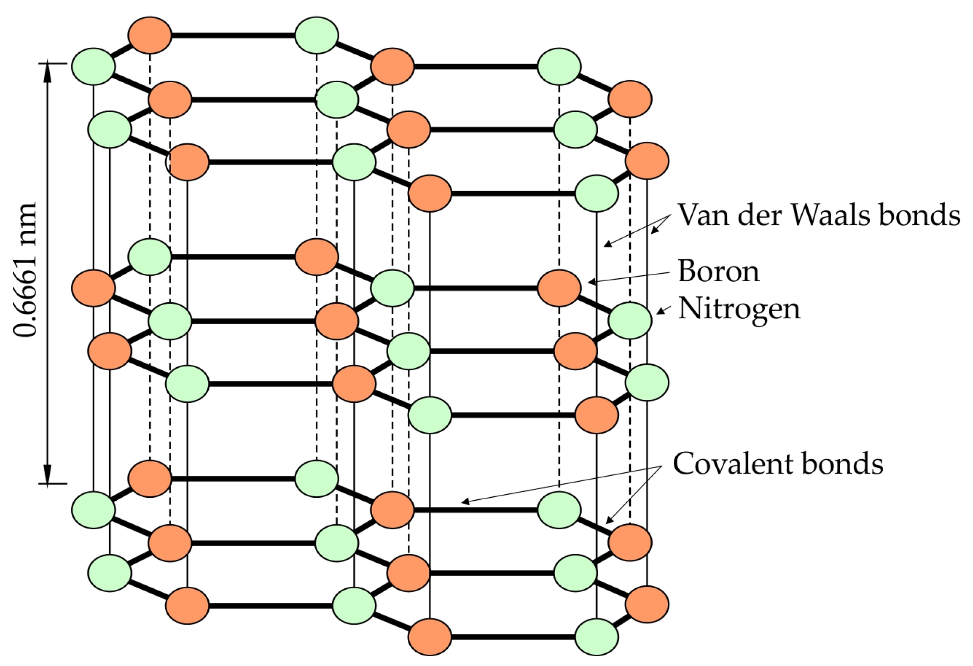
Hexagonal boron nitride (h-BN) has a layered structure, similar to transition metal dichalcogenides, in which a covalent bond holds each layer while the bond between the layers is a van der Waals bond [28]. The crystal structure of boron nitride consists of hexagonal rings containing boron and nitrogen atoms bound at an angle of 120° (Figure 16). Layers of boron nitride shear very quickly under load along the basal plane, ensuring the improvement of tribological properties of self-lubricating coatings [174]. The sliding of the layers along the basal plane is recognised as the main mechanism that promotes lubricity. A review of the self-lubricating materials used in heavily loaded friction pairs is provided by John and Menezes [175].
Torres et al. [177] investigated additively manufactured maraging steel high temperature sheet metal forming tools in addition to different types of self-lubricating coatings deposited by means of laser metal deposition (LMD). It was found that the use of Ni-based self-lubricating coatings contributes to a more stable frictional behaviour in the functionalised 3D-printed tools. The related technique of selective laser melting (SLM) is also well suited to the preparation of functional materials with protective coatings and with the incorporation of solid lubricants [178]. The results of Torres et al.’s work [177] confirm the enormous potential of using the combination of LMD with SLM for tool functionalisation. Aschauer et al. [179] developed a novel high-temperature self-lubricating coating system based on a Mo–Si–B top layer. Four PVD-coated W360 tool materials were tested when hot sheet metal forming Al–Si-coated 22MnB5 steel sheets. The coatings investigated involved a homogeneously grown Mo–Si–B coating on top of a TiN base layer [180] and a nanostructured multilayer system (Ti1-xAlxN/Mo–Si–B) [181]. As a reference, an oxidation-resistant Al–Cr–O-based thin film and a DLC-based coating system were investigated. The lowest wear was found in the tools protected with coatings providing interdiffusion with the counterbody and low adhesion. Two coatings met these criteria: Ti0.57Al0.43N/Mo–Si–B multilayer and DLC.
Self-lubricating coatings are used under sheet metal forming conditions with high pressures, in which it is difficult to ensure the continuity of the lubricating film. They are also used under the conditions of sheet metal forming at high temperatures, which make it difficult to select classic lubricants resistant to high temperatures. In view of the growing expectations in terms of environmental protection, self-lubricating coatings have the potential to be used in lubricant-free sheet metal forming tools in the automotive industry. Self-lubricating materials are particularly used in stamping tools for cold sheet metal forming. The use of self-lubricating coatings in hot plastic working is very limited owing to the occurrence of very high unit pressures and high temperatures.
6. Structured and Textured Tool Surfaces
Surface finishing may improve the tribological conditions between the tools and the sheets. Besides mill finishing, shot blasting and laser beam texturing, electrical discharge texturing (EDT) is the most common technology used for the surface finishing of metal sheets. A comprehensive overview of EDT processes used for producing sheets with EDT surfaces has been provided by Aspinwall et al. [182] and Simão et al. [183].
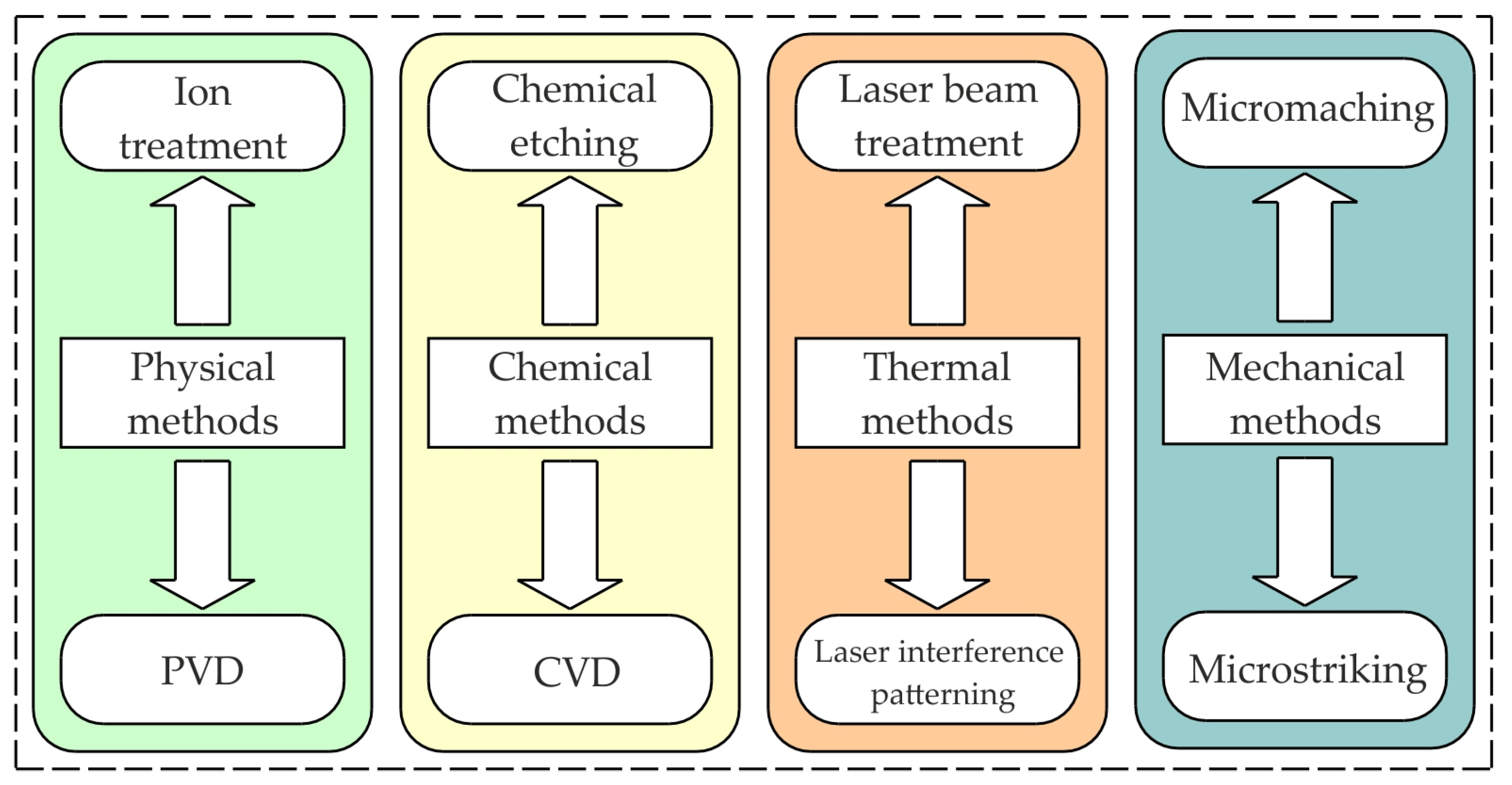
The combination of modern coatings (nanostructured, nanolayered, nanocomposite, etc.) and the construction of self-lubricating tools containing microchannels and pockets constituting a reservoir of lubricant are very promising and effective ways to increase the efficiency of lubrication under high-pressure conditions [28]. The basic texturing methods can be divided into mechanical, physical and thermal methods (Figure 17). The oil cavities lead to a reduction in the COF under conditions of mixed and full film lubrication [184,185]. Considering dry friction, the reduction in the real contact area and the storage of wear particles in cavities can be listed as the main effects contributing to the improvement of tribological properties [186]. By optimising the texture dimensions, it is possible to retain the lubricant and improve the hydrodynamic effect [187]. The positive effects of single-scale textures depend largely on the type of contact (conformal or non-conformal) and the lubrication regime [188].
The formation of regular dimples on the surface stimulates anti-wear and friction-reducing mechanisms, which depend on the degree and type of surface texture and lubrication conditions [28]. Among the many shapes of texturing depressions, e.g., crossed and parallel channels [189], triangular cavities [190], square cavities [191] and more complex shapes [192], the most studied structures are spherical cavities owing to their ease of fabrication [193]. In addition, the density of the pits plays an important role as it affects the relubrication process of the sheet metal surface as it travels over the tool surface. The distance between the individual depressions filled with grease should be smaller than the distance at which the lubricating film loses its properties. Textures can show a preferential direction or be arranged randomly [194]. The viscosity of the lubricant, the thickness of the lubricant film, and the sliding speed affect the maximum spacing of the pits [195]. Most studies focus on determining the optimal values of these parameters in order to obtain tribological conditions that ensure the minimisation of friction and increase the load capacity of the lubricating film.
Wang [193] included the retention of wear particles and a reduction in wear associated with the participation of a third body in the friction node as the advantages of texturing. The depressions in the surface of the tools can retain wear debris, act as lubricant microreservoirs, and generate a separation effect between the rubbing surfaces as a result of hydrodynamic lubrication [196,197]. The basic texturing techniques of metal forming tools are hammering [198], laser machining [199], electrical discharge machining [200] and burnishing [201].
The parameters of the hammering process have a major influence on the resulting surface roughness of deep drawing tools [202]. Owing to work hardening and the induction of residual compressive stresses [203], the hammering process generally leads to an increase in hardness on the surface and in the near-surface layer by up to 30% [198]. According to Lehnert and Hildebrand [204], the increased value of the COF of textured surfaces can be explained by macroscopic mechanical interactions between the bodies of the friction pair. Increased frictional resistance significantly affects the nature of sheet metal movement in the die, and thus the product quality and tool wear [205]. Micro-texturing the surface of deep drawing tools can significantly reduce friction in certain areas of the drawpiece [198]. Šugárová et al. [206] indicated that a surface density of depressions in the area of 13% is preferred to reduce the value of the COF. An areal density of pits above 20% usually causes an increase in the COF and wear rate [198].
Laser texturing has become the main texturing method owing to its high efficiency, excellent controllability, environmental friendliness and accuracy [28]. During ablation or photolytic processing, melting and evaporation of the material occurs when a high-energy laser beam hits the work surface [207]. Wang et al. [208] analysed the effects of different textures on the surfaces of tools produced with a nanosecond fibre laser on the tribological conditions at the interface between the moulded material and the tool. The authors analysed many shapes of the depressions (elliptical, spherical, S-shaped) and their distribution (radial, tetragonal and hexagonal) on the surface of the tools in relation to the direction of sheet metal movement. The use of a surface texture consisting of dimples arranged in a radial pattern contributed to the most significant reduction in friction by approximately 40%. On the other hand, this surface texture contributed to an increase in the surface roughness parameters, the Ra parameter increased from 0.41 μm to 2.19 μm, and the Rz parameter increased from 0.99 μm to 16.79 μm. Mousavi et al. [195] used direct laser interference patterning (DLIP) to texture the surface of the die used for the U-shaped bending process. Patterns resembling longitudinal lines in the direction of sheet travel show better performance in reducing the COF compared to patterns composed of transverse and cross cavities, owing to their tendency for mechanical interaction with surface asperities of the workpiece. Sedlaček et al. [209] performed the laser texturing of the surface of K890 cold work steel tools before and after TiAIN coating deposition to investigate the effect of the surface-texturing process sequence on its fatigue life. It has been found that when laser texturing is performed after applying the coating, the fatigue strength properties of the tool surface are impaired. Surface observations have revealed quasi-plastic cracks and small flat areas with clear evidence of a brittle fracture mechanism with cleavage. Podgornik et al. [210] and Sedlaček et al. [211] showed that the combination of hard coatings on tools used for high-performance punches and dies for SMF with additional surface-texturing improves the tribological properties of the tools. Leshchynsky et al. [212] used laser micromachining technologies to create a network of microchannels serving as lubrication pockets to collect and retain lubricant containing MoS2 nanoparticles on the surface of a TiAlN–MB-coated tool. It was found that MoS2 nanoparticles produced using rolling cleavage technology have a layered graphene-like structure. It was shown that the graphene-like MoS2 nanoparticles have unique tribological properties: a low COF value (0.05–0.08) and a low degree of wear.
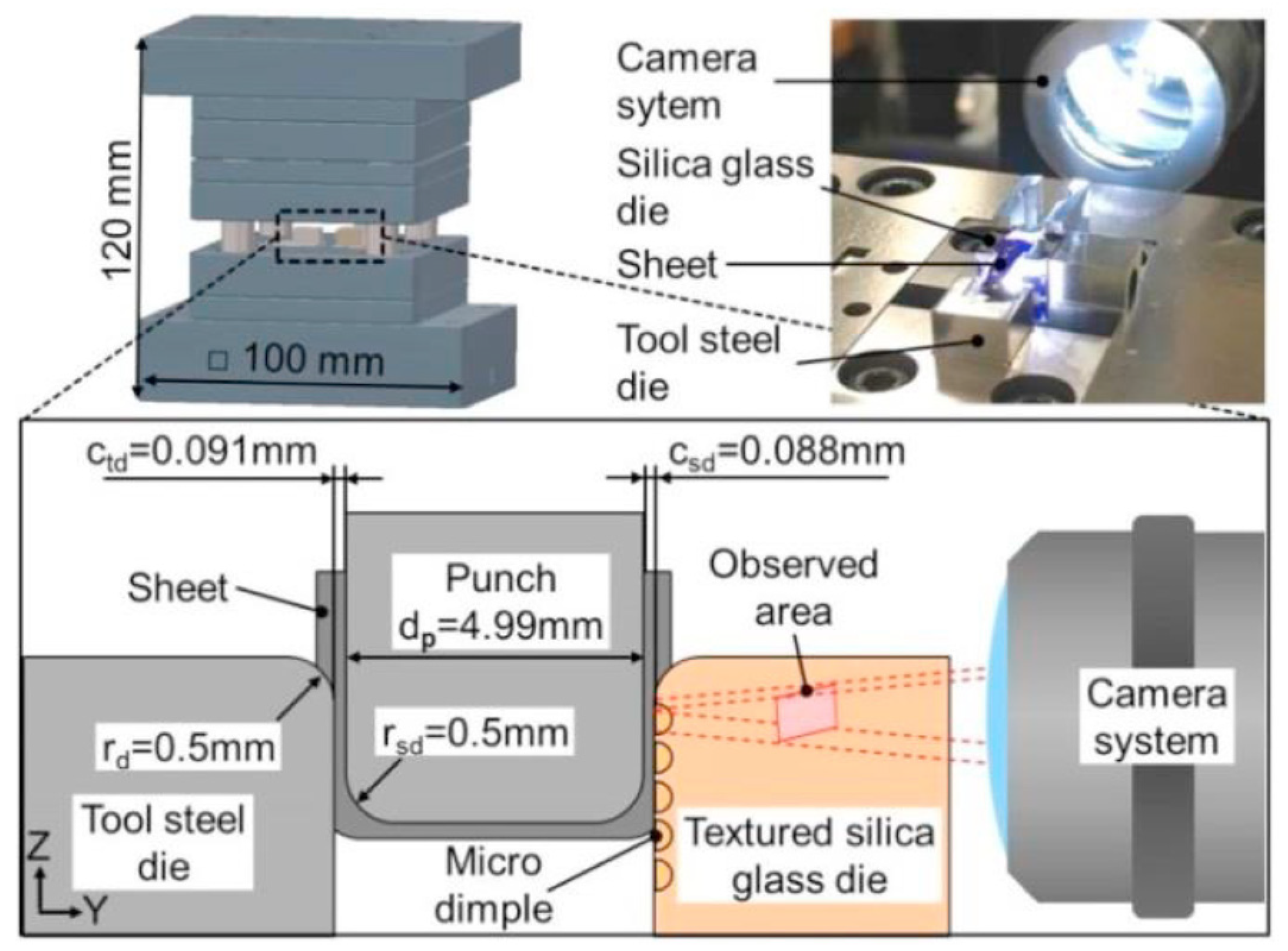
To observe the contact surface during the SMF process, Vorholt et al. [213] developed an in-situ observation system using transparent quartz glass matrices with a recording camera (Figure 18). The aim of the research was to correlate the dimensional parameters of microtextured structures produced by femto-/pico-second laser treatment with the tribological properties during the deep drawing of X6CrNi18-10 stainless steel sheets. The matrix textured with dimples of 10 μm and 50 μm in diameter showed flows of lubricant from one dimple structure to the other. The authors correlated this effect with the formation of hydrodynamic pressure inside the cavities. Large microcavities with a diameter of 100 μm showed less air bubble formation and less lubricant flow in the contact area.
Mazurkiewicz [214] presented a method of preparing the surface texture of the X210Cr12 steel matrix by chemical etching. Microscopic analyses of the surface texture formed under the conditions of different etching times showed a certain determined pattern, ensuring hydrophilicity of the die surface. The chemically etched surface texture effectively reduced the COF between flat countersamples under oil emulsion lubrication and high load conditions (nominal pressure ≥ 32 MPa), with an average reduction in COF of 35.6%. The greatest reduction in COF (by 49.5%) was obtained under nominal pressures of 72 MPa.
Most of the research on surface-texturing focuses on optimising the texture parameters (shape, depth, orientation and spacing of the cavities) in order to obtain optimal friction performance [197]. However, there is a gap in the research on the effects of friction pair materials on the friction properties of textured surfaces, which limits the practical application of surface-texturing of tools. A review of modelling techniques and the key findings of the lubrication of textured surfaces is provided by Gropper et al. [215] and Huang et al. [216].
Tool surface-texturing is used to improve the efficiency and control friction in stamping industry. On the one hand, texturing the surface of the tool reduces the contact area of the stamping die and blankholder within the workpiece. On the other hand, micro-pockets incorporated on the tool surface significantly improve the boundary lubrication regime. Lubricant pockets can also act as a lubricant reservoir in conditions where it is difficult to ensure the continuity of the lubricant film in punching and stamping operations. A surface pattern with grooves provides lubricant reservoirs to enhance the lubrication effect and reduce the COF [217]. Hazrati et al. [218] used the surface-texturing of X153CrMoV12 steel die for the U-bend forming of DP800 steel. Sulaiman et al. [219] prevented the occurrence of galling in the strip reduction process via the application of surface-texturing. Steitz et al. [198] demonstrated that the hardening effect due to hammer-peened surface-texturing can lead to an increase in the wear resistance of stamping tools used in deep drawing. Another method for the surface-texturing of deep drawing tools is etching [220].
7. Summary
Friction occurring between the surfaces of the deformed material and the forming tools has a significant impact on the efficiency of the SMF process and the properties of the final components. In the SMF processes carried out under dry friction conditions, the COF is the result of the coexistence of two main friction mechanisms: adhesion occurring in the areas of real contact and the mechanical interaction of the surface asperities. Ensuring the surface of tools with appropriate physical and mechanical properties is the basic indicator of tool reliability.
SMF at elevated temperatures increases the plasticity of the deformed material, but at the same time intensifies the phenomenon of adhesion on the contact interface. In the context of the selection of the appropriate grade of tool material, the chemical affinity of the materials of the rubbing pair should be mentioned. Adhesive bonding occurs at the contact of two metal surfaces characterised by high chemical affinity. There are also two types of adhesive joints, diffusion and non-diffusion, while in the SMF of metals, under conditions of elevated temperature and high pressure, friction joints of the diffusion type are dominant.
Lubrication is essential to ensure the reliability of tool surfaces. The application of wear-resistant coatings is the most economical and effective way to reduce the harmful effects of friction in SMF operations. Although high-performance coatings increase the cost of manufacturing the tool, they also extend the period of failure-free operation. The prospective effects of reducing tool wear can be obtained by texturing their surfaces. The oil trapped in the cavities can act as a lubricant reservoir, and at the same time the real contact area is reduced.
The type of lubricant, as well as the the method of its application and distribution, affect the course of the SMF process. The lubricant should be adapted to the prevailing pressures in the forming zone and the temperature of the operation to ensure the durability of the lubricating film. Above temperatures of around 500 °C, liquid lubricants such as mineral oils decompose, and therefore heat-resistant solid lubricants are the only choice for hot SMF processes.
Among the anti-wear coatings, the most popular are those based on titanium nitride, titanium carbonitride and titanium nitride. Intensive development has been seen in diamond and carbon coatings that reduce wear, friction and corrosion, e.g., diamond-like carbon coatings, which show better anti-adhesive properties than conventional coatings. The main goals of applying coatings on SMF tools are to increase surface hardness, extend tool life, reduce the COF value and reduce diffusion under elevated temperature conditions.
The techniques of vapour deposition, PVD and CVD use physical and chemical phenomena, respectively, to modify the surface layers of tools. PVD techniques involve physical phenomena such as sublimation or sputtering, which are intensified by additional reactive (using reactive gases) or activated (activating gas and metal vapour ionisation processes) processes. Coatings obtained by the PVD method are characterised by increased hardness and lower abrasive wear.
The method of applying coatings by CVD is used primarily to apply coatings on tools made of sintered carbides and ceramic materials. TiC or TiN coatings applied with the CVD method ensure durability up to several times greater than conventionally sintered carbides. In addition, CrN, CrC, CrN, TiAlN, AlTiN, TiCN and ZrN coatings, diamond-like coatings and self-lubricating coatings containing MoS2 are used on tools in SMF.
It should be noted that forming tools for sheet metal forming are mainly made of cold work tool steels, hot work tool steels and tool steels. Smaller tools are made of tungsten carbide, and tool concepts with composite inserts are also known. Laser, vacuum carburising and nitriding technologies, as well as PVD and CVD coatings, are used to increase the durability of moulding tools made of tool steels. In recent years, the development of technology has resulted in the expansion of new applications for anti-wear coatings. Duplex coatings (a nitrided/TiN layer) are used to protect the surfaces of dies used for the cold working of copper, aluminium and carbon steels. CVD methods are most often used to produce coatings of carbides, nitrides, carbonitrides and metal oxides on ceramic tools and cold work steel tools. In addition to tungsten carbides and conventional tool steels, sintered steels are available with many different combinations of properties to suit different applications. The minimum thickness of PVD coating such as AlTiN, CrN, TiN and TiCN used for metal stamping and forming applications should not be less than 4–5 microns. PVD coatings are preferably used on tool steels since the low deposition temperature will not result in the softening of the base material. CVD coatings are usually applied in multiple layers. The CVD coating nucleates on the metal carbides. Therefore, excellent candidates for CVD coating include all cemented carbide materials, as well as AISI D, AISI H, AISI M and AISI T steels. Steels such as AISI A2 and AISI S7 should not be coated with CVD processes if the tool will be subjected to impact loads, as the coating temperature is higher than the austenitising temperature of these steels [221]. Thermal reactive diffusion is a high-temperature coating process used for producing metal carbides (usually vanadium carbide) on the surface of a carbon-containing substrate. The methods used for surface-texturing the regular or stochastic patterns incorporated on the surfaces of tools are mainly based on steel tools. Kataoka et al. [77] studied the advantages of ceramic materials such as Al2O3, SiC and Si3N4 as tool materials for a drawing die. To achieve lubricant-free conditions, the forming process can also be realised using self-lubricating coating systems [75].
Funding
This research received no external funding.
Data Availability Statement
The data presented in this study are available on request from the corresponding author.
Conflicts of Interest
The authors declare no conflict of interest.
References
- Czichos, H.; Habig, K.H. Tribologie-Handbuch-Tribologie, Tribomaterialien, Tribotechnik, 3rd ed.; ViehwegþTeubner Verlag: Wiesbaden, Germany, 2010. [Google Scholar]
- Bang, J.; Song, J.; Bae, G.; Park, N.; Lee, M.; Kim, H. Quantitative evaluation of experimental wear behaviour for CrN-coated tool steels in sheet metal forming process of TRIP 1180. Procedia Manuf. 2020, 50, 791–794. [Google Scholar] [CrossRef]
- Bang, J.; Kim, M.; Bae, G.; Song, J.; Kim, H.G.; Lee, M.G. Quantitative Evaluation of Tool Wear in Cold Stamping of Ultra-High-Strength Steel Sheets. Met. Mater. Int. 2023, 29, 327–342. [Google Scholar] [CrossRef]
- Luiz, V.D.; Santos, A.J.D.; Câmara, M.A.; Rodrigues, P.C.D.M. Influence of Different Contact Conditions on Friction Properties of AISI 430 Steel Sheet with Deep Drawing Quality. Coatings 2023, 13, 771. [Google Scholar] [CrossRef]
- Cora, Ö.N.; Koç, M. Wear resistance evaluation of hard-coatings for sheet blanking die. Procedia Manuf. 2018, 15, 590–596. [Google Scholar] [CrossRef]
- Trzepieciński, T.; Kaščák, L. Assessment of frictional performance of deep drawing quality steel sheets used in automotive industry. Technol. Autom. Montażu 2022, 115, 37–44. [Google Scholar] [CrossRef]
- Nilsson, A.; Kirkhorn, L.; Andersson, M.; Stahl, J.E. Improved tool wear properties in sheet metal forming using Carbide Steel, a novel abrasion resistant cast material. Wear 2011, 271, 1280–1287. [Google Scholar] [CrossRef]
- Kumar, S.; Singh, H.; Kumar, R.; Chohan, J.S. Parametric optimization and wear analysis of AISI D2 steel components. Mater. Today Proc. 2023, in press. [Google Scholar] [CrossRef]
- Żaba, K.; Kuczek, Ł.; Puchlerska, S.; Wiewióra, M.; Góral, M.; Trzepieciński, T. Analysis of Tribological Performance of New Stamping Die Composite Inserts Using Strip Drawing Test. Adv. Mech. Mater. Eng. 2023, 40, 55–62. [Google Scholar] [CrossRef]
- Ikonnikov, D.A.; Semenov, I.E. Thin sheet metal forming with composite material. IOP Conf. Ser. Mater. Sci. Eng. 2020, 734, 012070. [Google Scholar] [CrossRef]
- Trzepieciński, T.; Malinowski, T.; Pieja, T. Experimental and numerical analysis of industrial warm forming of stainless steel sheet. J. Manuf. Process. 2017, 30, 532–540. [Google Scholar] [CrossRef]
- Tondini, F.; Basso, A.; Arinbjarnar, U.; Nielsen, C.V. The Performance of 3D Printed Polymer Tools in Sheet Metal Forming. Metals 2021, 11, 1256. [Google Scholar] [CrossRef]
- Pinto, M.; Santos, A.D.; Teixeira, P.; Bolt, P.J. Study on the usability and robustness of polymer and wood materials for tooling in sheet metal forming. J. Mater. Proc. Technol. 2008, 202, 47–53. [Google Scholar] [CrossRef]
- Joghan, H.D.; Hahn, M.; Sehrt, J.T.; Tekkaya, A.E. Hybrid additive manufacturing of metal laminated forming tools. CIRP Ann. 2022, 71, 225–228. [Google Scholar] [CrossRef]
- Witulski, J.; Trompeter, M.; Tekkaya, A.E.; Kleiner, M. High wear resistant deep drawing tools made of coated polymers. CIRP Ann.-Manuf. Technol. 2011, 60, 311–314. [Google Scholar] [CrossRef] [Green Version]
- de Souza, J.H.C.; Liewald, M. Analysis of the tribological behaviour of polymer composite tool materials for sheet metal forming. Wear 2010, 268, 241–248. [Google Scholar] [CrossRef]
- Olofsson, U.; Zhu, Y.; Abbasi, S.; Lewis, R.; Lewis, S. Tribology of the wheel-rail contact aspects of wear, particle emission and adhesion. Veh. Syst. Dyn. 2013, 51, 1091–1120. [Google Scholar] [CrossRef]
- Sulaiman, M.H.; Farahana, R.N.; Bienk, K.; Nielsen, C.V.; Bay, N. Effects of DLC/TiAlN-coated die on friction and wear in sheet-metal forming under dry and oil-lubricated conditions: Experimental and numerical studies. Wear 2019, 438–439, 203040. [Google Scholar] [CrossRef]
- Geueke, M.; Frohn-Sörensen, P.; Reuter, J.; Padavu, N.; Reinicke, T.; Engel, B. Structural optimization of additively manufactured polymer tools for flexible sheet metal forming. Procedia CIRP 2021, 104, 1345–1350. [Google Scholar] [CrossRef]
- Trzepiecinski, T.; Lemu, H.G. Recent Developments and Trends in the Friction Testing for Conventional Sheet Metal Forming and Incremental Sheet Forming. Metals 2020, 10, 47. [Google Scholar] [CrossRef] [Green Version]
- Trzepieciński, T.; Najm, S.M.; Oleksik, V.; Vasilca, D.; Paniti, I.; Szpunar, M. Recent Developments and Future Challenges in Incremental Sheet Forming of Aluminium and Aluminium Alloy Sheets. Metals 2022, 12, 124. [Google Scholar] [CrossRef]
- Trzepieciński, T.; Szpunar, M.; Dzierwa, A.; Żaba, K. Investigation of Surface Roughness in Incremental Sheet Forming of Conical Drawpieces from Pure Titanium Sheets. Materials 2022, 15, 4278. [Google Scholar] [CrossRef] [PubMed]
- Szewczyk, M.; Szwajka, K.; Trzepieciński, T. Frictional Characteristics of Deep-Drawing Quality Steel Sheets in the Flat Die Strip Drawing Test. Materials 2022, 15, 5236. [Google Scholar] [CrossRef] [PubMed]
- Wang, X.Z. Tool Wear Prediction Modelling for Sheet Metal Stamping Die in Automotive Manufacture. Ph.D. Thesis, Swinburne University of Technology, Hawthorn, Australia, 24 March 2011. [Google Scholar]
- Shanbhag, V.V.; Pereira, P.M.; Rolfe, F.B.; Arunachalam, N. Time series analysis of tool wear in sheet metal stamping using acoustic emission. J. Phys. Conf. Ser. 2017, 896, 012030. [Google Scholar] [CrossRef] [Green Version]
- Arinbjarnar, U.; Nielsen, C.V. Effect of workpiece pre-straining on tribological performance of surface coatings in sheet metal forming. Tribol. Int. 2023, 180, 108262. [Google Scholar] [CrossRef]
- Dong, H. Tribological properties of titanium-based alloy. In Surface Engineering of Light Alloys; Dong, H., Ed.; Woodhead Publishing: Sawston, UK, 2010; pp. 58–80. [Google Scholar]
- Trzepieciński, T. Tarcie i Smarowanie w Procesach Kształtowania Blach; Wydawnictwo Naukowe PWN: Warszawa, Poland, 2023. [Google Scholar]
- Dobrzański, L.A.; Dobrzańska-Danikiewicz, A.D. Technologie kształtowania struktury i własności powierzchni materiałów inżynierskich przez nanoszenie powłok z fazy gazowej. In Kształtowanie Struktury i Własności Powierzchni Materiałów Inżynierskich i Biomedycznych; Dobrzański, L.A., Ed.; International OCSCO World Press: Gliwice, Poland, 2009; pp. 22–27. [Google Scholar]
- Fejkiel, R.; Goleń, P. Application of the Finite Element Method to Simulate the Friction Phenomenon in a Strip Drawing Test. Adv. Mech. Mater. Eng. 2023, 40, 39–46. [Google Scholar] [CrossRef]
- Lemu, H.G.; Trzepieciński, T. Numerical and experimental study of frictional behavior in bending under tension test. Stroj. Vestn.-J. Mech. Eng. 2013, 59, 41–49. [Google Scholar] [CrossRef]
- Trzepieciński, T.; Kubit, A.; Slota, J.; Fejkiel, R. An experimental study of the frictional properties of steel sheets using the drawbead simulator test. Materials 2019, 12, 4037. [Google Scholar] [CrossRef] [Green Version]
- Trzepieciński, T.; Lemu, H.G. Frictional conditions of AA5251 aluminium alloy sheets using drawbead simulator tests and numerical methods. Stroj. Vestn.-J. Mech. Eng. 2014, 60, 51–60. [Google Scholar] [CrossRef] [Green Version]
- Okonkwo, P.C.; Kelly, G.; Rolfe, B.F.; Pereira, M.P. The effect of temperature on sliding wear of steel-tool steel pairs. Wear 2012, 282–283, 22–30. [Google Scholar] [CrossRef]
- Wu, Y.; Recklin, V.; Groche, P. Strain Induced Surface Change in Sheet Metal Forming: Numerical Prediction, Influence on Friction and Tool Wear. J. Manuf. Mater. Process. 2021, 5, 29. [Google Scholar] [CrossRef]
- Bang, J.; Kim, M.; Bae, G.; Kim, H.-G.; Lee, M.-G.; Song, J. Efficient Wear Simulation Methodology for Predicting Nonlinear Wear Behavior of Tools in Sheet Metal Forming. Materials 2022, 15, 4509. [Google Scholar] [CrossRef] [PubMed]
- Gåård, A. Wear in Sheet Metal Forming. Ph.D. Thesis, Karlstad University, Karlstad, Sweden, 2008. [Google Scholar]
- Jaworski, J.; Mucha, J.; Trzepieciński, T. Kształtowanie Trwałości Eksploatacyjnej Narzędzi do Przeróbki Plastycznej Metali; Oficyna Wydawnicza Politechniki Rzeszowskiej: Rzeszów, Poland, 2018. [Google Scholar]
- Berkowski, L. Stale Szybkotnące na Narzędzia do Obróbki Plastycznej; Instytut Obróbki Plastycznej: Poznań, Poland, 1994.
- Masen, M. Abrasive Tool Wear in Metal Forming Processes. Ph.D. Thesis, University of Twente, Enschede, The Netherlands, 15 September 2004. [Google Scholar]
- Dobrzański, L.A.; Dobrzańska-Danikiewicz, A.D. Obróbka powierzchni materiałów inżynierskich. Zmiany struktury i własności powierzchni materiałów inżynierskich w wyniku eksploatacji. Open Access Libr. 2011, 5, 368–416. [Google Scholar]
- Podgornik, B.; Leskovšek, V. Wear mechanisms and surface engineering of forming tools. Mater. Technol. 2015, 49, 313–324. [Google Scholar]
- Pereira, M.P.; Yan, W.; Rolfe, B.F. Sliding distance, contact pressure and wear in sheet metal stamping. Wear 2010, 268, 1275–1284. [Google Scholar] [CrossRef]
- ASTM Standard G98-91; Standard Test Method for Galling Resistance of Materials. ASTM: West Conshohocken, PA, USA, 1991.
- Groche, P.; Moeller, N.; Hoffmann, H.; Suh, J. Influence of gliding speed and contact pressure on the wear of forming tools. Wear 2011, 271, 2570–2578. [Google Scholar] [CrossRef]
- Karlsson, P.; Gåård, A.; Krakhmalev, P.; Bergström, J. Galling resistance and wear mechanisms for cold-work tool steels in lubricated sliding against high strength stainless steel sheets. Wear 2012, 286–287, 92–97. [Google Scholar] [CrossRef]
- Pelcastre, L. Hot Forming Tribology: Galling of Tools and Associated Problems; Luleå University of Technology: Lulea, Sweden, 2011. [Google Scholar]
- Archard, J.F. Contact and rubbing of flat surfaces. J. Appl. Phys. 1953, 24, 981–988. [Google Scholar] [CrossRef]
- Bayer, R.G. A general model for sliding wear in electrical contacts. Wear 1993, 162–164, 913–918. [Google Scholar] [CrossRef]
- Rhee, S.K. Wear equation for polymers sliding against metal surfaces. Wear 1970, 16, 431–445. [Google Scholar] [CrossRef]
- Gåård, A.; Krakhmalev, P.; Bergström, J. Influence of tool steel microstructure on origin of galling initiation and wear mechanisms under dry sliding against a carbon steel sheet. Wear 2009, 267, 387–393. [Google Scholar] [CrossRef]
- Ersoy-Nürnberg, K.; Nürnberg, G.; Golle, M.; Hoffmana, H. Simulation of wear on sheet metal forming tools—An energy approach. Wear 2008, 265, 1801–1807. [Google Scholar] [CrossRef]
- Ubhayaratne, I.; Pereira, M.P.; Xiang, Y.; Rolfe, B.F. Audio signal analysis for tool wear monitoring in sheet metal stamping. Mech. Syst. Signal Process. 2017, 85, 809–826. [Google Scholar] [CrossRef]
- Shanbhag, V.V.; Rolfe, B.F.; Arunachalam, N.; Pereira, M.P. Investigating galling wear behaviour in sheet metal stamping using acoustic emissions. Wear 2018, 414–415, 31–42. [Google Scholar] [CrossRef]
- Kubik, C.; Molitor, D.A.; Rojahn, M.; Groche, P. Towards a real-time tool state detection in sheet metal forming processes validated by wear classification during blanking. IOP Conf. Ser. Mater. Sci. Eng. 2022, 1238, 012067. [Google Scholar] [CrossRef]
- Molitor, D.A.; Kubik, C.; Hetfleisch, R.H.; Groche, P. Workpiece image-based tool wear classification in blanking processes using deep convolutional neural networks. Prod. Eng. 2022, 16, 481–492. [Google Scholar] [CrossRef]
- Kubik, C.; Becker, M.; Molitor, D.A.; Groche, P. Towards a systematical approach for wear detection in sheet metal forming using machine learning. Prod. Eng. 2023, 17, 21–36. [Google Scholar] [CrossRef]
- Tröber, P.; Demmel, P.; Hoffman, H.; Golle, R.; Volk, W. On the influence of Seebeck coefficients on adhesive tool wear during sheet metal processing. CIRP Ann. 2017, 66, 293–296. [Google Scholar] [CrossRef]
- Groche, P.; Christiany, M.; Wu, Y. Load-dependent wear in sheet metal forming. Wear 2019, 422–423, 252–260. [Google Scholar] [CrossRef]
- Sieczkarek, P.; Wernicke, S.; Gies, S.; Tekkaya, A.E.; Krebs, E.; Wiederkehr, P.; Biermann, D.; Tillmann, W.; Stangier, D. Wear behavior of tribologically optimized tool surfaces for incremental forming processes. Tribol. Int. 2016, 104, 64–72. [Google Scholar] [CrossRef]
- Schewe, M.; Wilbuer, H.; Menzel, A. Simulation of wear and effective friction properties of microstructured surfaces. Wear 2021, 464–465, 203491. [Google Scholar] [CrossRef]
- Gierzyńska, M. Tarcie, Zużycie i Smarowanie w Obróbce Plastycznej Metali; Wydawnictwa Naukowo-Techniczne: Warszawa, Poland, 1983. [Google Scholar]
- Bong, H.J.; Barlat, F.; Ahn, D.C.; Kim, H.Y.; Lee, M.G. Formability of austenitic and ferritic stainless steels at warm forming temperature. Int. J. Mech. Sci. 2013, 75, 94–109. [Google Scholar] [CrossRef]
- Pereira, M.P.; Weiss, M.; Rolfe, B.F.; Hilditch, T.B. The effect of the die radius profile accuracy on wear in sheet metal stamping. Int. J. Mach. Tools Manuf. 2013, 66, 44–53. [Google Scholar] [CrossRef]
- Pereira, M.P.; Yan, W.; Rolfe, B.F. Wear at the die radius in sheet metal stamping. Wear 2012, 274–275, 355–367. [Google Scholar] [CrossRef]
- Behrens, B.A.; Maier, H.J.; Hübner, S.; Bonk, C.; Almohallami, A.; Lummer, C.; Schein, P.; Scheland, H.; Micke-Camuz, M. Wear Behavior of MoS2 Lubricant Layers During Sheet Metal Forming. Procedia Eng. 2017, 183, 357–362. [Google Scholar] [CrossRef] [Green Version]
- Wang, X.Z.; Masood, S.H. Investigation of die radius arc profile on wear behaviour in sheet metal processing of advanced high strength steels. Mater. Des. 2011, 32, 1118–1128. [Google Scholar] [CrossRef]
- Luiz, V.D.; de Matos Rodrigues, P.C. Failure analysis of AISI 430 stainless steel sheet under stretching and bending conditions. Int. J. Adv. Manuf. Technol. 2022, 121, 2759–2772. [Google Scholar] [CrossRef]
- Luiz, V.D.; de Matos Rodrigues, P.C. Design of a Tribo-Simulator for Investigation of the Tribological Behavior of Stainless-Steel Sheets Under Different Contact Conditions. Mater. Res. 2022, 25, e20210220. [Google Scholar] [CrossRef]
- Krawiec, S. Kompozycje Smarów Plastycznych i Stałych w Procesie Tarcia Stalowych Węzłów Maszyn; Oficyna Wydawnicza Politechniki Wrocławskiej: Wrocław, Poland, 2011. [Google Scholar]
- Bello, D.O.; Walton, S. Surface topography and lubrication in sheet metal forming. Tribol. Int. 1987, 20, 59–65. [Google Scholar] [CrossRef]
- Trzepieciński, T. Recent developments and trends in sheet metal forming. Metals 2020, 10, 779. [Google Scholar] [CrossRef]
- Żaba, K.; Puchlerska, S.; Kuczek, Ł.; Trzepieciński, T.; Maj, P. Effect of Step Size on the Formability of Al/Cu Bimetallic Sheets in Single Point Incremental Sheet Forming. Materials 2023, 16, 367. [Google Scholar] [CrossRef]
- Lemu, H.G.; Trzepieciński, T.; Kubit, A.; Fejkiel, R. Friction modeling of Al-Mg alloy sheets based on multiple egression analysis and neural networks. Adv. Sci. Technol. Res. J. 2017, 11, 48–57. [Google Scholar] [CrossRef] [Green Version]
- Trzepieciński, T.; Szpunar, M.; Kašcák, L. Modeling of friction phenomena of Ti-6Al-4V sheets based on backward elimination regression and multi-layer artificial neural networks. Materials 2021, 14, 2570. [Google Scholar] [CrossRef] [PubMed]
- Yilkiran, D.; Wulff, D.; Almohallami, A.; Özkaya, F.; Bouguecha, A.; Hübner, S.; Möhwald, K.; Maier, H.J.; Behrens, B.A. Wear behaviour of thermally oxidised tool surfaces as low-friction separation layers for dry sheet metal forming. Wear 2017, 376–377, 1789–1803. [Google Scholar] [CrossRef]
- Podstawy Techniki Smarowniczej. Available online: https://totalenergies.pl/system/files/atoms/files/rozdzial_02_podstawy_techniki_smarowniczej.pdf (accessed on 29 December 2021).
- Płaza, S.; Margilewski, L.; Celichowski, G. Wstęp do Tribologii i Tribochemii; Wydawnictwo Uniwersytetu Łódzkiego: Łódź, Poland, 2005. [Google Scholar]
- Renevier, N.M.; Hampshire, J.; Fox, V.C.; Allen, T.; Teer, D.G. Advantage of using self-lubricating, hard, wear-resistant MoS2-based coatings. Surf. Coat. Technol. 2001, 142–144, 67–77. [Google Scholar] [CrossRef]
- Owuna, F.J.; Dabai, M.U.; Sokoto, M.A.; Dangoggo, S.M.; Bagudo, B.U.; Birnin-Yauri, U.A.; Hassan, L.G.; Sada, I.; Abubukar, A.L.; Jibrin, M.S. Chemical modification of vegetable oils for the production of biolubricants using trimethylolpropane: A review. Egypt. J. Pet. 2020, 29, 75–82. [Google Scholar] [CrossRef]
- Trzepieciński, T. Tribological performance of environmentally friendly bio-degradable lubricants based on a combination of boric acid and bio-based oils. Materials 2020, 13, 3892. [Google Scholar] [CrossRef]
- Biresaw, G.; Erhan, S.M. Solid lubricant formulations containing starch-soybean oil composites. J. Am. Oil Chem. Soc. 2002, 79, 291–296. [Google Scholar] [CrossRef]
- Bexell, U.; Olsson, M.; Johansson, M.; Samuelsson, J.; Sundell, P.E. A tribological study of a novel pre-treatment with linseed oil bonded to mercaptosilane treated aluminium. Surf. Coat. Technol. 2023, 166, 141–152. [Google Scholar] [CrossRef]
- Zareh-Desari, B.; Davoodi, B. Assessing the lubrication performance of vegetable oil-based nano-lubricants for environmentally conscious metal forming processes. J. Clean. Prod. 2016, 135, 1198–1209. [Google Scholar] [CrossRef]
- Szewczyk, M.; Szwajka, K. Assessment of the Tribological Performance of Bio-Based Lubricants Using Analysis of Variance. Adv. Mech. Mater. Eng. 2023, 40, 31–38. [Google Scholar] [CrossRef]
- Nanayakkara, N.K.B.M.P.; Narayanan, R.G. Friction and lubrication in sustainable metal forming. In Sustainable Material Forming and Joining; Narayanan, R.G., Gunasekera, J.S., Eds.; CRC Press: Boca Raton, FL, USA, 2019; pp. 59–76. [Google Scholar]
- Fox, N.J.; Tyrer, B.; Stachowiak, G.W. Boundary lubrication performance of free fatty acids in sunflower oil. Tribol. Lett. 2004, 16, 275–281. [Google Scholar] [CrossRef]
- Mobarak, H.M.; Mohamad, E.N.; Masjuki, H.H.; Kalam, M.A.; Al Mahmud, K.A.H.; Habibullah, M.; Ashraful, A.M. The prospects of biolubricants as alternatives in automotive applications. Renew. Sust. Energy Rev. 2014, 33, 34–43. [Google Scholar] [CrossRef]
- Peng, Y.; Hu, Y.; Wang, H. Tribological behaviors of surfactant-functionalized carbon nanotubes as lubricant additive in water. Tribol. Lett. 2007, 25, 247–253. [Google Scholar] [CrossRef]
- Chen, C.S.; Chen, X.H.; Xu, L.S.; Yang, Z.; Li, W.H. Modification of multi-walled carbon nanotubes with fatty acid and their tribological properties as lubricant additive. Carbon 2005, 43, 1660–1666. [Google Scholar] [CrossRef]
- Cornelio, J.A.C.; Cuervo, P.; Palacio, L.M.H.; Lara-Romero, J.; Toro, A. Tribological properties of carbon nanotubes as lubricant additive in oil and water for a wheel—Rail system. J. Mater. Res. Technol. 2016, 5, 68–76. [Google Scholar] [CrossRef] [Green Version]
- Pawar, R.V.; Hulwan, D.B.; Mandale, M.B. Recent advancements in synthesis, rheological characterization, and tribological performance of vegetable oil-based lubricants enhanced with nanoparticles for sustainable lubrication. J. Clean. Prod. 2022, 378, 134454. [Google Scholar] [CrossRef]
- Uppar, R.; Dinesha, P.; Kumar, S. A critical review on vegetable oil-based bio-lubricants: Preparation, characterization, and challenges. Environ. Dev. Sustain. 2022. [Google Scholar] [CrossRef]
- Tokar, D.; Radek, N.; Mikina, A.; Kalinowski, A. Właściwości Powłok DLC Teksturowanych Laserowo. Available online: https://www.iskra-zmils.com.pl/library/2021/03/11/wlasciwosci-powlok-dlc-teksturowanych-laserowo.pdf (accessed on 16 December 2021).
- Lovell, M.R.; Deng, Z. Characterization of interfacial friction in coated sheet steels: Influence of stamping process parameters and wear mechanisms. Tribol. Int. 2002, 35, 85–95. [Google Scholar] [CrossRef]
- Kim, A.; Han, B.; Yan, Q.; Altan, T. Evaluation of tool materials, coatings and lubricants in forming galvanized advanced high strength steels (AHSS). CIRP Ann. 2008, 57, 299–304. [Google Scholar] [CrossRef]
- Dobrzański, L.A. Ogólna klasyfikacja warstw powierzchniowych i procesów ich wytwarzania. In Kształtowanie Struktury i Własności Powierzchni Materiałów Inżynierskich i Biomedycznych; Dobrzański, L.A., Ed.; International OCSCO World Press: Gliwice, Poland, 2009; pp. 22–27. [Google Scholar]
- Dobrzańska-Danikiewicz, A.D.; Jonda, E.; Labisz, K. Foresight methods application for evaluating laser treatment of hot-work steels. J. Achiev. Mater. Manuf. Eng. 2010, 43, 750–773. [Google Scholar]
- De Hosson, J.T.M.; Ocelik, V. Functionally graded materials produced with high power laser. Mater. Sci. Forum 2003, 426–432, 123–130. [Google Scholar] [CrossRef]
- Jaworski, J.; Trzepieciński, T. Możliwości Zapewnienia Jakościowego Wykonania Narzędzi z Oszczędnościowej Stali Szybkotnącej; Oficyna Wydawnicza Politechniki Rzeszowskiej: Rzeszów, Poland, 2014. [Google Scholar]
- Senthil, K.P.; Jegadheesan, C.; Somasundaram, P.; Praveen, K.S.; Vivek, A.A.; Ajit, P.S.; Jeyaprakash, N. State of art: Review on laser surface hardening of alloy metals. Mater. Today Proc. 2023, in press. [Google Scholar] [CrossRef]
- Dobrzański, L.A.; Bonek, M.; Piec, M.; Jonda, E. Diode laser modification of surface gradient layer properties of a hot-work tool steel. Mater. Sci. Forum 2006, 532–533, 657–660. [Google Scholar] [CrossRef]
- Burakowski, T.; Wierzchoń, T. Inżynieria Powierzchni Metali. Podstawy, Urządzenia, Technologia; Wydawnictwa Naukowo-Techniczne: Warszawa, Poland, 1995. [Google Scholar]
- Temmler, A.; Cortina, M.; Ross, I.; Küpper, M.E.; Rittinghaus, S.K. Evolution of Surface Topography and Microstructure in Laser Polishing of Cold Work Steel 1.2379 (AISI D2) Using Quadratic, Top-Hat Shaped Intensity Distributions. Materials 2022, 15, 769. [Google Scholar] [CrossRef]
- Förster, D.J.; Weber, R.; Holder, D.; Graf, T. Estimation of the depth limit for percussion drilling with picosecond laser pulses. Opt. Express 2018, 26, 11546–11552. [Google Scholar] [CrossRef] [Green Version]
- Häfner, T.; Heberle, J.; Hautmann, H.; Zhao, R.; Tenner, J.; Tremmel, S.; Merklein, M.; Schmidt, M. Effect of Picosecond Laser Based Modifications of Amorphous Carbon Coatings on Lubricant-free Tribological Systems. JLMN-J. Laser Micro/Nanoeng. 2017, 12, 132–140. [Google Scholar] [CrossRef]
- Jähnig, T.; Mousavi, A.; Steinhorst, M.; Roch, T.; Brosius, A.; Lasagni, A.F. Friction reduction in dry forming by using tetrahedral amorphous carbon coatings and laser micro-structuring. Dry Met. Form. 2019, 5, 25–30. [Google Scholar]
- Hasselbruch, H.; Lu, Y.; Messaoudi, H.; Mehner, A.; Vollertsen, F. Tribological Properties of Multi-Layer a-C:H:W/a-C:H PVD-Coatings Micro-Structured by Picosecond Laser Ablation. Key Eng. Mater. 2019, 809, 439–444. [Google Scholar] [CrossRef]
- Henn, M.; Reichardt, G.; Weber, R.; Graf, T.; Liewald, M. Dry Metal Forming Using Volatile Lubricants Injected into the Forming Tool Through Flow-Optimized, Laser-Drilled Microholes. JOM 2020, 72, 2517–2524. [Google Scholar] [CrossRef] [Green Version]
- Dobrzański, L.A.; Kwaśny, W.; Brytan, Z.; Shishkov, R.; Tomov, B. Structure and properties of the Ti + Ti(C,N) coatings obtained in the PVD process on sintered high speed steel. J. Mater. Process. Technol. 2004, 157–158, 312–316. [Google Scholar] [CrossRef]
- Liewald, M.; Wagner, S.; Becker, D. Anisotropie des tribologischen verhaltens beim tiefziehen von Feinblechen. Tribol. Schmier. 2010, 57, 25–29. [Google Scholar]
- Liu, X.; Liewald, M.; Becker, D. Effects of rolling direction and lubricant on friction in sheet metal forming. J. Tribol. 2009, 131, 042101042108. [Google Scholar] [CrossRef]
- PVD czy CVD—Metody Nanoszenia Powłok na Narzędzia. Available online: https://magazynprzemyslowy.pl/artykuly/pvd-czy-cvd-metody-nanoszenia-powlok-na-narzedzia (accessed on 30 December 2021).
- Sitek, W. Metodologia Projektowania Stali Szybkotnących z Wykorzystaniem Narzędzi Sztucznej Inteligencji; International OCSCO World Press: Gliwice, Poland, 2010. [Google Scholar]
- Burakowski, T.; Wierzchoń, T. Surface Engineering of Metals—Principles, Equipment, Technologies; CRC Press LLC: Boca Raton, FL, USA, 1999. [Google Scholar]
- McKenzie, D.R.; McFall, W.D.; Sainty, W.G.; Yin, Y.; Durandet, A.; Boswell, R.W. New technology for PACVD. Surf. Coat. Technol. 1996, 82, 326–333. [Google Scholar] [CrossRef]
- Malarde, D.; Powell, M.J.; Quesada-Cabrera, R.; Wilson, R.L.; Carmalt, C.J.; Sankar, G.; Parkin, I.P.; Palgrave, R.G. Optimized Atmospheric-Pressure Chemical Vapor Deposition Thermochromic VO2 Thin Films for Intelligent Window Applications. ACS Omega 2017, 2, 1040–1046. [Google Scholar] [CrossRef] [Green Version]
- Hulkko, J.G.; Qiu, R.; Bäcke, O.; Forslund, A.; Halvarsson, M.; Larsson, H.; Boman, M. Low-pressure CVD of (Tix,W1-x)Ny from WF6, TiCl4 and NH3. Surf. Coat. Technol. 2022, 438, 128394. [Google Scholar] [CrossRef]
- Dos Santos, B.C.; Rodrigues, A.M.; Mueller, R.; Lora, F.A.; Nascimento, M.L.F.; Pinto, H.C.; Coelho, R.S. Tribological Investigations on Tool Surfaces for Temperature-Supported Forming of Magnesium AZ31 Sheets. Materials 2020, 13, 2465. [Google Scholar]
- Tillmann, W.; Stangier, D. Application of Nanostructured Bionic Thin Layers to Enhance the Wear and Friction Behavior of Tools for Sheet-Bulk Metal Forming. In Sheet Bulk Metal Forming; Merklein, M., Tekkaya, A.E., Behrens, B.A., Eds.; TCRC73 2020, Lecture Notes in Production Engineering; Springer: Cham, Switzerland, 2021; pp. 216–238. [Google Scholar]
- Lister, M. Vanadium carbide diffusion coatings for tool and die components. ASM Proc. Heat Treat. 2006, 2006, 162–166. [Google Scholar]
- Janoss, B.J. PVD/CVD coatings for stamping and forming of stainless steels. In Technical Papers-Society of Manufacturing Engineers, Proceedings of the 1999 Conference Forming and Fabricating Stainless Steel, Springfield, MA, USA, 2-4 June 1999; Society of Manufacturing Engineers: Dearborn, MI, USA, 1999; pp. 99–199. [Google Scholar]
- Escher, C.; Henke, T. New trends in thin coatings for sheet metal forming tools. In Proceedings of the 6th International Tooling Conference: The Use of Tool Steels: Experience and Research, Karlstad University, Karlstad, Sweden, 10–13 September 2002; pp. 919–933. [Google Scholar]
- Balaceanu, M.; Braic, M.; Braic, V.; Pavelescu, G. Properties of arc plasma deposited TiCN/ZrCN superlattice coatings. Surf. Coat. Technol. 2005, 200, 1084–1087. [Google Scholar] [CrossRef]
- Zeng, X.T. TiN/NbN superlattice hard coatings deposited by unbalanced magnetron sputtering. Surf. Coat. Technol. 1999, 113, 75–79. [Google Scholar] [CrossRef]
- Wysiecki, M. Nowoczesne Materiały Narzędziowe; Wydawnictwa Naukowo-Techniczne: Warszawa, Poland, 1997. [Google Scholar]
- Hovsepian, P.E.; Münz, W.D. Synthesis, structure and applications of nanoscale multilayer/superlattice structured PVD coatings. In Nanostructured Coatings; Cavaleiro, A., De Hosson, J.T.M., Eds.; Springer: New York, NY, USA, 2006; pp. 555–643. [Google Scholar]
- Hultman, L. Synthesis, structure and properties of superhard superlattice coatings. In Nanostructured Coatings; Cavaleiro, A., De Hosson, J.T.M., Eds.; Springer: New York, NY, USA, 2006; pp. 539–554. [Google Scholar]
- Czechowski, K.; Wrońska, I. Powłoki nanostrukturalne na narzędzia skrawające. Mechanik 2011, 84, 96–99. [Google Scholar]
- Spain, E.; Avelar-Batista, J.C.; Letch, M.; Housden, J.; Lerga, B. Characterization and application of Cr-Al-N coatings. Surf. Coat. Technol. 2005, 200, 1507–1513. [Google Scholar] [CrossRef]
- Kim, S.K.; Vinh, P.V.; Kim, J.H.; Ngoc, T. Deposition of superhard TiAlSiN thin films by cathodic arc plasma deposition. Surf. Coat. Technol. 2005, 200, 1391–1394. [Google Scholar] [CrossRef]
- Reiter, A.E.; Derfinger, V.H.; Hanselmann, B.; Bachmann, T.; Sartory, B. Investigation of the properties of Al1-xCrxN coatings by cathodic arc evaporation. Surf. Coat. Technol. 2005, 200, 2114–2122. [Google Scholar] [CrossRef]
- Stein, C.; Keunecke, M.; Bewilogua, K.; Chudoba, T.; Kölker, W.; van den Berg, H. Cubic boron nitride based coating systems with different interlayers for cutting inserts. Surf. Coat. Technol. 2011, 205, 103–106. [Google Scholar] [CrossRef]
- Luo, Q. Temperature dependent friction and wear of magnetron sputtered coating TiAlN/VN. Wear 2011, 271, 2058–2066. [Google Scholar] [CrossRef] [Green Version]
- Chang, Y.Y.; Wang, D.Y.; Hung, C.Y. Structural and mechanical properties of nanolayered TiAlN/CrN coatings synthesized by arc deposition process. Surf. Coat. Technol. 2005, 200, 1702–1708. [Google Scholar] [CrossRef]
- Wu, H.; Qin, L.; Dong, G.; Hua, M.; Yang, S.; Zhang, J. An investigation on the lubrication mechanism of MoS2 nano sheet in point contact: The manner of particle entering the contact area. Tribol. Int. 2017, 107, 48–55. [Google Scholar] [CrossRef]
- Zhang, S.; Sun, D.; Fu, Y.; Pei, Y.T.; De Hosson, J.T.M. Ni—Toughened nc-TiN/a-SiNx nanocomposite thin films. Surf. Coat. Technol. 2005, 194, 119–127. [Google Scholar]
- Settineri, L.; Faga, M.G.; Gautier, G.; Perucca, M. Evaluation of wear resistance of AlSiTiN and AlSiCrN nanocomposite coatings for cutting tools. Surf. Coat. Technol. 2008, 57, 575–578. [Google Scholar] [CrossRef]
- Viet, M.V.; Thinh, N.T.; Sy, L.V.; Antonov, S. Study on the formability by TPIF technology for aluminium sheet at room temperature. E3S Web Conf. 2020, 207, 05005. [Google Scholar] [CrossRef]
- Park, J.K.; Baik, Y.J. The crystalline structure, hardness and thermall stability of AlN/CrN superlattice coating prepared by D.C. magnetron sputtering. Surf. Coat. Technol. 2005, 200, 1519–1523. [Google Scholar] [CrossRef]
- Flink, A.; Larsson, T.; Sjölén, J.; Karlsson, L.; Hultman, L. Influence of Si on the microstructure of arc evaporated (Ti, Si)N thin films; evidence for cubic solid solutions and their thermal stability. Surf. Coat. Technol. 2005, 200, 1535–1542. [Google Scholar] [CrossRef]
- Sakurai, M.; Toihara, T.; Wang, M.; Kurosaka, W.; Miyake, S. Surface morphology and mechanical properties of nanoscale TiAlN/SiNx multilayer coating deposited by reactive magnetron sputterin. Surf. Coat. Technol. 2008, 203, 171–179. [Google Scholar] [CrossRef]
- Kim, S.K.; Le, V.V.; Vinh, P.V.; Lee, J.W. Effect of cathode arc current and bias voltage on the mechanical properties CrAlSiN thin films. Surf. Coat. Technol. 2008, 202, 5400–5404. [Google Scholar] [CrossRef]
- Ghiotti, A.; Bruschi, S. Tribological behaviour of DLC coatings for sheet metal forming tools. Wear 2011, 271, 2454–2458. [Google Scholar] [CrossRef]
- Shoba, C.H.; Siva Prasad, D. Cathodic arc TiAlN PVD coatings for machining applications. Mater. Sci. Indian J. 2016, 12, 142–146. [Google Scholar]
- Taube, K. Carbon-based coatings for dry sheet-metal working. Surf. Coat. Technol. 1998, 98, 976–984. [Google Scholar] [CrossRef]
- Murakawa, M.; Takeuchi, S. Evaluation of tribological properties of DLC films used in sheet forming of aluminum sheet. Surf. Coat. Technol. 2003, 163–164, 561–565. [Google Scholar] [CrossRef]
- Murakawa, M.; Koga, N.; Watanabe, S.; Takeuchi, S. Tribological behavior of amorphous hard carbon films against zinc-plated steel sheets. Surf. Coat. Technol. 1998, 108–109, 425–430. [Google Scholar] [CrossRef]
- Krachenfels, K.; Rothammer, B.; Zhao, R.; Tremmel, S.; Merklein, M. Influence of varying sheet material properties on dry deep drawing process. IOP Conf. Ser. Mater. Sci. Eng. 2019, 651, 012012. [Google Scholar] [CrossRef]
- Cha, S.C. Coatings for forming dies of advanced high-strength steel. In Coating Technology for Vehicle Applications; Cha, S., Erdemir, A., Eds.; Springer: Cham, Switzerland, 2015. [Google Scholar]
- Niu, R.; Li, J.; Wang, Y.; Chen, J.; Xue, Q. Structure and high temperature tribological behavior of TiAlN/nitride duplex treated coatings on Ti6Al4V. Surf. Coat. Technol. 2017, 309, 232–241. [Google Scholar] [CrossRef]
- Nouari, M.; Makich, H. On the physics of machining titanium alloys: Interactions between cutting parameters, microstructure and tool wear. Metals 2014, 4, 335–358. [Google Scholar] [CrossRef] [Green Version]
- Liu, A.; Deng, J.; Cui, H.; Chen, Y.; Zhao, J. Friction and wear properties of TiN, TiAlN, AlTiN and CrAlN PVD nitride coatings. Int. J. Refract. Metals Hard Mater. 2012, 31, 82–88. [Google Scholar]
- Poole, C.P.; Owens, F.J. Introduction to Nanotechnology; John Wiley & Sons Inc.: Hoboken, NJ, USA, 2003. [Google Scholar]
- Dobrzańska-Danikiewicz, A.D.; Gołombek, K.; Pakuła, D.; MIkuła, J.; Staszuk, M.; Żukowska, W. Long-term development directions of PVD/CVD coatings deposited onto sintered tool materials. Open Access Libr. 2011, 6, 278–330. [Google Scholar]
- Becker, D. Wear of nanostructured composite tool coatings. Wear 2013, 304, 88–95. [Google Scholar] [CrossRef]
- Chen, X.; Peng, Z.; Yu, X.; Fu, Z.; Yue, W.; Wang, C. Microstructure and tribological performance of self-lubricating diamond/tetrahedral amorphous carbon composite film. Appl. Surf. Sci. 2011, 257, 3180–3186. [Google Scholar] [CrossRef]
- Furlan, K.P.; Gonçalves, P.D.C.; Consoni, D.R.; Dias, M.V.G.; De Lima, G.A.; de Mello, J.D.B.; Klein, A.N. Metallurgical aspects of self-lubricating composites containing graphite and MoS2. J. Mater. Eng. Perform. 2017, 26, 1135–1145. [Google Scholar] [CrossRef]
- Quazi, M.M.; Fazal, M.A.; Haseeb, A.S.M.A.; Yusof, F.; Masjuki, H.H.; Arslan, A.A. Review to the laser cladding of self-lubricating composite coatings. Lasers Manuf. Mater. Process. 2016, 3, 67–99. [Google Scholar] [CrossRef]
- De Mello, J.D.B.; Binder, C.; Hammes, G.; Binder, R.; Klein, A.N. Tribological behaviour of sintered iron based self-lubricating composites. Friction 2017, 5, 285–307. [Google Scholar] [CrossRef] [Green Version]
- Nowe Nanopowłoki Ograniczają Tarcie i Zanieczyszczenia. Available online: https://cordis.europa.eu/article/id/89519-new-nanocoats-reduce-friction-and-pollution/pl (accessed on 2 May 2023).
- Mitsuno, A.; Akhadejdamrong, T.; Aizawa, T. Self-lubrication of Cl-implanted titanium nitride coating for dry metal forming. Mater. Trans. 2003, 44, 1295–1302. [Google Scholar] [CrossRef] [Green Version]
- Kotkowiak, M. Samosmarujące Warstwy Stopowane Laserowo i Materiały Spiekane Wytwarzane z Zastosowaniem Fluorków Wapnia i Baru. Ph.D. Thesis, Politechnika Poznańska, Poznań, Poland, 8 September 2021. [Google Scholar]
- Wang, H.M.; Yu, Y.L.; Li, S.Q. Microstructure and tribological properties of laser clad CaF2/Al2O3 self-lubrication wear-resistant ceramic matrix composite coatings. Scr. Mater. 2002, 47, 57–61. [Google Scholar] [CrossRef]
- Zhang, X.F.; Zhang, Z.L.; Wang, A.H.; Huang, Z.W. Microstructure and properties of HVOF sprayed Ni-based submicron WS2/CaF2 self-lubricating composite coating. trans. Nonferr. Met. Soc. China 2009, 19, 85–92. [Google Scholar] [CrossRef]
- Walck, S.D.; Zabinski, J.S.; McDevitt, N.T. Characterization of air-annealed, pulsed laser deposited ZnO–WS2 solid film lubricants by transmission electron microscopy. Thin Solid Films 1997, 305, 130–143. [Google Scholar] [CrossRef]
- Zabinski, J.S.; Donley, M.S.; Dyhouse, V.J. Chemical and tribological characterization of PbO–MoS2 films grown by pulsed laser deposition. Thin Solid Films 1992, 214, 156–163. [Google Scholar] [CrossRef]
- Muratore, C.; Veovodin, A.A. Molybdenum disulfide as a lubricant and catalyst in adaptive nanocomposite coatings. Surf. Coat. Technol. 2006, 201, 4125–4130. [Google Scholar] [CrossRef]
- Bobzin, K.; Brögelmann, T.; Kruppe, N.C.; Hoffmann, D.C.; Bergs, T.; Trauth, D.; Mannens, R.; Hild, R. Self-Lubricating PVD Coatings for Dry Cold Massive Forming. Available online: https://publications.rwth-aachen.de/record/780460/files/780460.pdf (accessed on 30 December 2021).
- Bobzin, K.; Brögelmann, T.; Kruppe, N.C.; Arghavani, M.; Hoffmann, D.C.; Klocke, F.; Mattfeld, P.; Trauth, D.; Hild, R. Mechanical and tribological characterization of self-lubricating (Cr1-xAlx)N coatings for deposition on complex-shaped forging tools. Dry Met. Form. Open Access J. 2013, 3, 81–89. [Google Scholar]
- Rajak, D.; Kumar, A.; Behera, A.; Menezes, P. Diamond-like carbon (DLC) coatings: Classification, properties, and applications. Appl. Sci. 2021, 11, 4445. [Google Scholar] [CrossRef]
- Berman, D.; Erdemir, A.; Sumant, A.V. Reduced wear and friction enabled by graphene layers on sliding steel surfaces in dry nitrogen. Carbon 2013, 59, 167–175. [Google Scholar] [CrossRef]
- Kasar, A.K.; Xiong, G.; Menezes, P.L. Graphene-reinforced metal and polymer matrix composites. JOM 2018, 70, 829–836. [Google Scholar] [CrossRef]
- Chen, J.; Chen, J.; Wang, S.; Sun, Q.; Cheng, J.; Yu, Y.; Yang, J. Tribological properties of h-BN matrix solid-lubricating composites under elevated temperatures. Tribol. Int. 2020, 148, 106333. [Google Scholar] [CrossRef]
- John, M.; Menezes, P.L. Self-lubricating materials for extreme condition applications. Materials 2021, 14, 5588. [Google Scholar] [CrossRef] [PubMed]
- Majety, S.; Cao, X.K.; Dahal, R.; Pantha, B.N.; Li, J.; Lin, J.Y.; Jiang, H.X. Semiconducting hexagonal boron nitride for deep ultraviolet photonics. Quantum Sens. Nanophotonic Devices 2012, 8268, 607–614. [Google Scholar]
- Torres, H.; Panaitescu, I.; Gangl, R.; Hubmann, R.; Scheerer, M.; Ripoll, M.R. Laser metal deposition of self-lubricating alloys on selective laser melting maraging tools for the high temperature forming of aluminium. Wear 2023, 524–525, 204883. [Google Scholar] [CrossRef]
- Żaba, K.; Tuz, L.; Noga, P.; Rusz, S.; Zabystrzan, R. Effect of Multi-Variant Thermal Treatment on Microstructure Evolution and Mechanical Properties of AlSi10Mg Processed by Direct Metal Laser Sintering and Casting. Materials 2022, 15, 974. [Google Scholar] [CrossRef]
- Aschauer, E.; Riedl, H.; Koller, C.M.; Bolvardi, H.; Arndt, M.; Polcik, P.; Mayrhofer, P.H. Adhesive wear formation on PVD coated tools applied in hot forming of Al-Si coated steel sheets. Wear 2019, 430–431, 309–316. [Google Scholar] [CrossRef]
- Aschauer, E.; Sackl, S.; Schachinger, T.; Bolvardi, H.; Arndt, M.; Polcik, P.; Riedl, H.; Mayrhofer, P.H. Atomic scale investigations of thermally treated nano-structured Ti-Al-N/Mo-Si-B multilayers. Surf. Coat. Technol. 2018, 349, 480–487. [Google Scholar] [CrossRef]
- Riedl, H.; Koller, C.M.; Limbeck, A.; Kalaš, J.; Polcik, P.; Mayrhofer, P.H. Oxidation behavior and tribological properties of multilayered Ti-Al-N/Mo-Si-B thin films. J. Vac. Sci. Technol. A 2015, 33, 05E129. [Google Scholar] [CrossRef]
- Aspinwall, D.K.; Wise, M.L.H.; Stout, K.J.; Gho, T.H.A.; Zhao, F.L.; EI-Menshawy, M.F. Electrical discharge texturing. Int. J. Mach. Tools Manuf. 1992, 32, 183–193. [Google Scholar] [CrossRef]
- Simão, J.; Aspinwall, D.K.; Wise, M.L.H.; EI-Menshawy, M.F. Mill roll texturing using EDT. J. Mater. Process. Technol. 1994, 45, 207–214. [Google Scholar] [CrossRef]
- Podulka, P. The Effect of Surface Topography Feature Size Density and Distribution on the Results of a Data Processing and Parameters Calculation with a Comparison of Regular Methods. Materials 2021, 14, 4077. [Google Scholar] [CrossRef]
- Podulka, P. Improved Procedures for Feature-Based Suppression of Surface Texture High-Frequency Measurement Errors in the Wear Analysis of Cylinder Liner Topographies. Metals 2021, 11, 143. [Google Scholar] [CrossRef]
- Gachot, C.; Rosenkranz, A.; Reinert, L.; Ramos-Moore, E.; Souza, N.; Müser, M.H.; Mücklich, F. Dry friction between laser-patterned surfaces: Role of alignment, structural wavelength and surface chemistry. Tribol. Lett. 2013, 49, 193–202. [Google Scholar] [CrossRef]
- Bijani, D.; Deladi, E.L.; De Rooij, M.B.; Schipper, D.J. The Influence of Surface Texturing on the Film Thickness in Starved Lubricated Parallel Sliding Contacts. Lubricants 2018, 6, 61. [Google Scholar] [CrossRef] [Green Version]
- Grützmacher, P.G.; Profito, F.J.; Rosenkranz, A. Multi-scale surface texturing in tribology—Current knowledge and future perspectives. Lubricants 2019, 7, 95. [Google Scholar] [CrossRef] [Green Version]
- Kawasegi, N.; Sugimori, H.; Morimoto, H.; Morita, N.; Hori, I. Development of cutting tools with microscale and nanoscale textures to improve frictional behaviour. Precis. Eng. 2009, 33, 248–254. [Google Scholar] [CrossRef]
- Geiger, M.; Roth, S.; Becker, W. Influence of laser-produced microstructures on the tribological behavior of ceramics. Surf. Coat. Technol. 1998, 100–101, 17–22. [Google Scholar] [CrossRef]
- Kim, D.E.; Cha, K.H.; Sung, I.H.; Bryan, J. Design of surface micro-structures for friction control in micro-systems applications. CIRP Ann.-Manuf. Technol. 2002, 51, 495–498. [Google Scholar] [CrossRef]
- Costa, H.L.; Hutchings, I.M. Hydrodynamic lubrication of textured steel surfaces under recipro-cating sliding conditions. Tribol. Int. 2007, 40, 1227–1238. [Google Scholar] [CrossRef]
- Wang, L. Use of structured surfaces for friction and wear control on bearing surfaces. Surf. Topogr. Metrol. Prop. 2014, 2, 043001. [Google Scholar] [CrossRef]
- Abdel Aal, H.A. Functional surfaces for tribological applications: Inspiration and design. Surf. Topogr. Metrol. Prop. 2016, 4, 043001. [Google Scholar] [CrossRef]
- Mousavi, A.; Sperk, T.; Gietzelt, T.; Kunze, T.; Lasagni, A.F.; Brosius, A. Effect of contact area on friction force in sheet metal forming operations. Key Eng. Mater. 2018, 767, 77–84. [Google Scholar] [CrossRef]
- Varenberg, M.; Halperin, G.; Etsion, I. Different aspects of the role of wear debris in fretting wear. Wear 2002, 252, 902–910. [Google Scholar] [CrossRef]
- Wakuda, M.; Yamauchi, Y.; Kanzaki, S.; Yasuda, Y. Effect of surface texturing on friction reduction between ceramic and steel materials under lubricated sliding contact. Wear 2003, 254, 356–363. [Google Scholar] [CrossRef]
- Steitz, M.; Stein, P.; Groche, P. Influence of hammer-peened surface textures on friction behavior. Tribol. Lett. 2015, 58, 24. [Google Scholar] [CrossRef]
- Šugár, P.; Šugárová, J.; Frnčík, M. Laser surface texturing of tool steel: Textured surfaces quality evaluation. Open Eng. 2016, 6, 90–97. [Google Scholar] [CrossRef]
- Zabala, A.; Galdos, L.; Childs, C.; Llavori, I.; Aginagalde, A.; Mendiguren, J.; Saenz de Argandoña, E. The Interaction between the sheet/tool surface texture and the friction/galling behaviour on aluminium deep drawing operations. Metals 2021, 11, 979. [Google Scholar] [CrossRef]
- Franzen, V.; Witulski, J.; Brosius, A.; Trompeter, M.; Tekkaya, A.E. Textured surfaces for deep drawing tools by rolling. Int. J. Mach. Tools Manuf. 2010, 50, 969–976. [Google Scholar] [CrossRef]
- Steitz, M.; Scheil, J.; Müller, C.; Groche, P. Effect of process parameters on surface roughness in hammer peening an deep rolling. Key Eng. Mater. 2013, 554–557, 1887–1901. [Google Scholar] [CrossRef]
- Hacini, L.; van Le, N. Effect of impact energy on residua stresses induced by hammer peening of 304L plate. J. Mater. Process. Technol. 2008, 208, 542–548. [Google Scholar] [CrossRef]
- Lehnert, W.; Hildebrand, M. Umformtechnische Vorgange in der Wirkfuge unter Berucksichtigung der Bedeutung der Schmier-Stoffe. Schmierung bei den Prozessen der Warm- und Kaltumformung; TU Bergakademie Freiberg: Freiberg, Germany, 1996. [Google Scholar]
- Kuwer, C.J. Verschleißreduktion beim Tiefziehen von X5CrNi18-10. Ph.D. Thesis, RWTH Aachen, Aachen, Germany, 20 July 2007. [Google Scholar]
- Šugárová, J.; Šugár, P.; Frnčík, M.; Necpal, M.; Moravčíková, J.; Kusý, M. The influence of the tool surface texture on friction and the surface layers properties of formed component. Adv. Sci. Technol. Res. J. 2018, 12, 181–193. [Google Scholar] [CrossRef]
- Shivakoti, I.; Kibria, G.; Cep, R.; Pradhan, B.B.; Sharma, A. Laser surface texturing for biomedical applications: A review. Coatings 2021, 11, 124. [Google Scholar] [CrossRef]
- Wang, X.X.; Zhan, M.; Fu, M.W.; Guo, J.; Xu, R.Q.; Lei, X.P. A unique spinning method for grain refinement: Repetitive shear spinning. Procedia Eng. 2017, 207, 1725–1730. [Google Scholar] [CrossRef]
- Sedlaček, M.; Guštin, A.Z.; Žužek, B. Influence of laser surface texturing sequence on fatigue properties of coated cold work tool steel. Metals 2020, 10, 1636. [Google Scholar] [CrossRef]
- Podgornik, B.; Sedlaček, M.; Čekada, M.; Jacobson, S.; Zajec, B. Impact of fracture toughness on surface properties of PVD coated cold work tool steel. Surf. Coat. Technol. 2015, 277, 144–150. [Google Scholar] [CrossRef]
- Sedlaček, M.; Batič, B.Š.; Česnik, D.; Podgornik, B. Influence of the substrate hardness and fracture toughness on the dynamic wear properties of coated tool steels. Mater. Technol. 2019, 53, 565–574. [Google Scholar] [CrossRef]
- Leshchynsky, V.; Ignatiev, M.; Wisniewska-Weinert, H.; Borowski, J.; Rybak, T.; Dobrovnik, I. Forging tools modification with graphene-like solid lubricant nanoparticles. J. Achiev. Mater. Manuf. Eng. 2010, 43, 341–348. [Google Scholar]
- Vorholt, J.; Shimizu, T.; Kobayashi, H.; Heinrich, L.; Flosky, H.; Vollertsen, F.; Yang, M. In-situ observation of lubricant flow on laser textured die surface in sheet metal forming. Procedia Eng. 2017, 207, 2209–2214. [Google Scholar] [CrossRef]
- Mazurkiewicz, A. Problems of modern surface engineering technology implementation. Adv. Manuf. Sci. Technol. 2002, 26, 67–80. [Google Scholar]
- Gropper, D.; Wang, L.; Harvey, T.J. Hydrodynamic lubrication of textured surfaces: A review of modeling techniques and key findings. Tribol. Int. 2016, 94, 509–529. [Google Scholar] [CrossRef] [Green Version]
- Huang, Q.; Shi, X.; Xue, Y.; Zhang, K.; Wu, C. Recent progress on surface texturing and solid lubricants in tribology: Designs, properties, and mechanisms. Mater. Today Commun. 2023, 35, 105854. [Google Scholar] [CrossRef]
- Zheng, K.; Lin, J.; Politis, D.J.; Den, T.A. An experimental investigation for macro-textured tool in hot stamping. MATEC Web Conf. 2015, 21, 05005. [Google Scholar] [CrossRef] [Green Version]
- Hazrati, J.; Stein, P.; Kramer, P.; van den Boogaard, A.H. Tool Texturing for Deep Drawing Applications. IOP Sci. Ser. Mater. Sci. Eng. 2018, 418, 012095. [Google Scholar] [CrossRef]
- Sulaiman, M.H.; Christiansen, P.; Bay, N. The Influence of Tool Texture on Friction and Lubrication in Strip Reduction Testing. Lubricants 2017, 5, 3. [Google Scholar] [CrossRef] [Green Version]
- Mei, T.; Zhang, D.; Zhang, Q. Study on the Anti-friction properties of chemically etched surface texture and its synergistic Anti-friction properties with nano-lubricating oil in sheet metal deep drawing process. IOP Conf. Ser. Mater. Sci. Eng. 2020, 967, 012091. [Google Scholar] [CrossRef]
- Coating for Stamping and Forming Tools. Available online: https://www.thefabricator.com/thefabricator/article/bending/coating-for-stamping-and-forming-tools (accessed on 31 May 2023).
Figure 1.
(a) Design and (b) fabrication of the hybrid SMF tool (reproduced with permission from Reference [15]; copyright © 2011 CIRP. Published by Elsevier Ltd.).
Figure 1.
(a) Design and (b) fabrication of the hybrid SMF tool (reproduced with permission from Reference [15]; copyright © 2011 CIRP. Published by Elsevier Ltd.).

Figure 2.
Scheme of the tribological system in SMF.

Figure 3.
Model of the surface layer of a tool (prepared based on [29]).
Figure 3.
Model of the surface layer of a tool (prepared based on [29]).

Figure 4.
Causes of damage and wear in SMF tools.

Figure 5.
Effect of loading duration on (a) wear volume and (b) wear coefficient (reproduced with permission from Reference [52]; copyright © 2008 Elsevier B.V.).
Figure 5.
Effect of loading duration on (a) wear volume and (b) wear coefficient (reproduced with permission from Reference [52]; copyright © 2008 Elsevier B.V.).

Figure 6.
Tool used for the instantaneous measurement of thermoelectric currents (reproduced with permission from Reference [58]; copyright © 2017 Published by Elsevier Ltd. on behalf of CIRP).
Figure 6.
Tool used for the instantaneous measurement of thermoelectric currents (reproduced with permission from Reference [58]; copyright © 2017 Published by Elsevier Ltd. on behalf of CIRP).

Figure 7.
Surface structures (Str1, Str2) of the forming tool (reproduced with permission from Reference [60]; copyright © 2016 Elsevier Ltd.).
Figure 7.
Surface structures (Str1, Str2) of the forming tool (reproduced with permission from Reference [60]; copyright © 2016 Elsevier Ltd.).

Figure 8.
Surface wear areas: (a) punch and die in deep drawing process, (b) punch and die in punching process: Fp—punch force, Fbh—blankholder force.
Figure 8.
Surface wear areas: (a) punch and die in deep drawing process, (b) punch and die in punching process: Fp—punch force, Fbh—blankholder force.

Figure 9.
Schematic of the channel forming wear test: (a) prior to and (b) at the end of the stamping process (reproduced with permission from Reference [64]; copyright © 2012 Elsevier Ltd.).
Figure 9.
Schematic of the channel forming wear test: (a) prior to and (b) at the end of the stamping process (reproduced with permission from Reference [64]; copyright © 2012 Elsevier Ltd.).

Figure 10.
Schematic and view of the test stand and the pressure measurements (reproduced with permission from Reference [66]; copyright © 2017 The Author(s). Published by Elsevier Ltd.).
Figure 10.
Schematic and view of the test stand and the pressure measurements (reproduced with permission from Reference [66]; copyright © 2017 The Author(s). Published by Elsevier Ltd.).

Figure 11.
Finite element model for simulation of the wear behaviour in the deep drawing simulations (reproduced with permission from Reference [67]; copyright © 2010 Elsevier Ltd.).
Figure 11.
Finite element model for simulation of the wear behaviour in the deep drawing simulations (reproduced with permission from Reference [67]; copyright © 2010 Elsevier Ltd.).

Figure 12.
Operational properties of the surface layer of plastic forming tools.

Figure 13.
Simulation tests for the SMF (reproduced with permission from Reference [18]; copyright © 2019 Elsevier B.V.).
Figure 13.
Simulation tests for the SMF (reproduced with permission from Reference [18]; copyright © 2019 Elsevier B.V.).

Figure 14.
The layer configuration of the newly developed tool coatings (reproduced with permission from Reference [156]; copyright © 2013 Elsevier B.V.).
Figure 14.
The layer configuration of the newly developed tool coatings (reproduced with permission from Reference [156]; copyright © 2013 Elsevier B.V.).

Figure 15.
Powder and fibre-based fillers in self-lubricating coatings.

Figure 16.
Structure diagram of hexagonal boron nitride (prepared based on [176]).
Figure 16.
Structure diagram of hexagonal boron nitride (prepared based on [176]).

Figure 17.
Surface-texturing methods.

Figure 18.
Scheme of the stand for in-situ observation of the friction zone (reproduced with permission from Reference [213]; copyright © 2017 Published by Elsevier Ltd.).
Figure 18.
Scheme of the stand for in-situ observation of the friction zone (reproduced with permission from Reference [213]; copyright © 2017 Published by Elsevier Ltd.).

Table 1.
Examples of PVD coatings (prepared based on [129]).
Table 1.
Examples of PVD coatings (prepared based on [129]).
| Structure of Coating | Type of Coating | Advantages |
|---|---|---|
| Single-layer coating | Cr–Al–N | High oxidation resistance, hardness higher than that of TiN and TiCN [130] |
| Ti–AlSiN | High hardness—48 GPa [131] | |
| Al1-xCrxN | High hardness—38 GPa [132] | |
| Multi-layer coating | TiAlN/cBN, CrTiAlSiN/cBN | Super-hardness—71~75 GPa [133] |
| Superstructure multi-layer coating | TiAlN/ZrN, TiAlN/CrN | Super-hardness—55~78 GPa [127] |
| TiAlN/VN | High hardness—42 GPa, Ra = 0.06 μm [134] | |
| Nanocrystal multi-layer coating | TiAlN/CrN | High hardness—37 GPa [135] |
| Nanolayer coating | CrN/WN | High hardness—31 GPa [136] |
| Nanocomposite coating | Nc-TiN/a-SiNx with addition of Ni | High fracture toughness, hardness—30 GPa [137] |
| AlSiTiN-Si3N4 | High hardness—40 GPa [138] | |
| AlCrSiN | Very high hardness and wear resistance [139] | |
| Superstructure nano-layer coating | AlN/CrN | Very high hardness—40 GPa [140] |
| Nanocrystalline single layer coating | Ti1-xSixN | Very high hardness—40 GPa, temperature resistance up to 900 °C [141] |
| Multi-later nano-coating | lN/SiNx | Hardness—32 GPa, high wear resistance [142] |
| CrAlSiN | High hardness—42 GPa [143] |
Disclaimer/Publisher’s Note: The statements, opinions and data contained in all publications are solely those of the individual author(s) and contributor(s) and not of MDPI and/or the editor(s). MDPI and/or the editor(s) disclaim responsibility for any injury to people or property resulting from any ideas, methods, instructions or products referred to in the content. |
© 2023 by the author. Licensee MDPI, Basel, Switzerland. This article is an open access article distributed under the terms and conditions of the Creative Commons Attribution (CC BY) license (https://creativecommons.org/licenses/by/4.0/).
Share and Cite
MDPI and ACS Style
Trzepieciński, T. Approaches for Preventing Tool Wear in Sheet Metal Forming Processes. Machines 2023, 11, 616. https://doi.org/10.3390/machines11060616
AMA Style
Trzepieciński T. Approaches for Preventing Tool Wear in Sheet Metal Forming Processes. Machines. 2023; 11(6):616. https://doi.org/10.3390/machines11060616
Chicago/Turabian StyleTrzepieciński, Tomasz. 2023. "Approaches for Preventing Tool Wear in Sheet Metal Forming Processes" Machines 11, no. 6: 616. https://doi.org/10.3390/machines11060616
Note that from the first issue of 2016, this journal uses article numbers instead of page numbers. See further details here.