
Design, Control and Stabilization of a Transformable Wheeled Fire Fighting Robot with a Fire-Extinguishing, Ball-Shooting Turret

Abstract
:1. Introduction
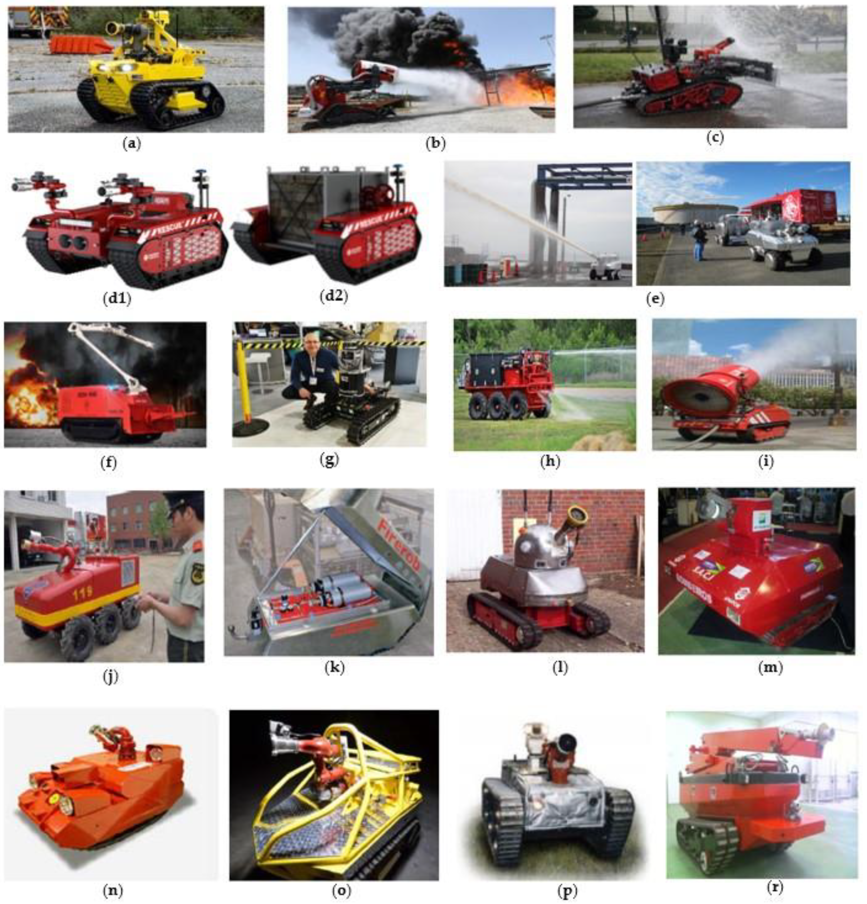
1.1. Related Works

| Robot Name | Locomotion System | Dimensions (mm) | Actuator Type/Size | Robot total Weight (kg) | Extinguisher Type | Velocity (km/h) | The Fire Response Range of the Robot (m) |
|---|---|---|---|---|---|---|---|
| FFR-1 [9] | pallet | 1620 × 1140 × 1380 | electric motor | 920 | Water Flow | 4 | - |
| Thermite RS1 [23,24] | pallets | 1962.15 × 1117.6 × 1625.6 | 24 hp diesel | 725 | Water Flow | 6 | - |
| Thermite RS3 [24] | pallets | 3048 × 1666.24 × 1638.3 | 36 hp diesel | 1588 | Water Flow | 8 | - |
| TAF35 [25] | pallets | 3000 × 1650 × 2200 | 71 hp diesel | 3900 | Water Flow | 9 | 60–80 |
| Colossus [26] | pallets | 1600 × 780 × 760 | 24 V electric motor | 485 | Water Flow | 3.5 | - |
| Milrem Multiscope Rescue with Hydra and Hose Cartridge [27,28] | pallets | 2400 × 2000 × 1150 | hybrid diesel/electric motor | 1630 | Water Flow | 20 | - |
| MVF-5 [29] | pallet | 3800 × 2180 × 2100 | 205 kW six-cylinder turbocharged diesel | 16,000 | Water Flow | 12 | - |
| Fire Ox [30] | 6-wheel | 10 hp diesel motor | - | Water Flow | - | - | |
| LUF 60 [31] | pallet | 2330 × 1350 × 2000 | 140 hp diesel motor | 2200 | Water Flow | 6 | 60 |
| FireMote-4800 [9,32] | pallet | 1400 × 700 × 1140 | electric motor | 450 | Water Flow | - | - |
| JMX-LT50 [9,33] | wheel | 2440 × 1440 × 1560 | diesel | 1500 | Water Flow | 12 | - |
| SACI 2.0 [9,34] | pallet | 1800 × 1500 × 1600 | electric motor | - | Water Flow | 20 | - |
| ArchiBot-M [9,35] | pallet | 1400 × 800 × 650 | - | 450 | Water Flow | 20 | - |
| MyBOT2000 [9,36] | pallet | 1500 × 1000 × 1300 | electric motor | 910 | Water Flow | 2.36 | - |
| Mitsubishi [3,37] | 4-wheel | 2170 × 1460 × 2070 | - | 1600 | Water Flow | 7.2 | - |
| FireRob [9,38] | pallet | 1300 × 685 × 385 | - | 240 | Water Flow | 3 | - |

1.2. Problem Statement, Contribution, and Novelty
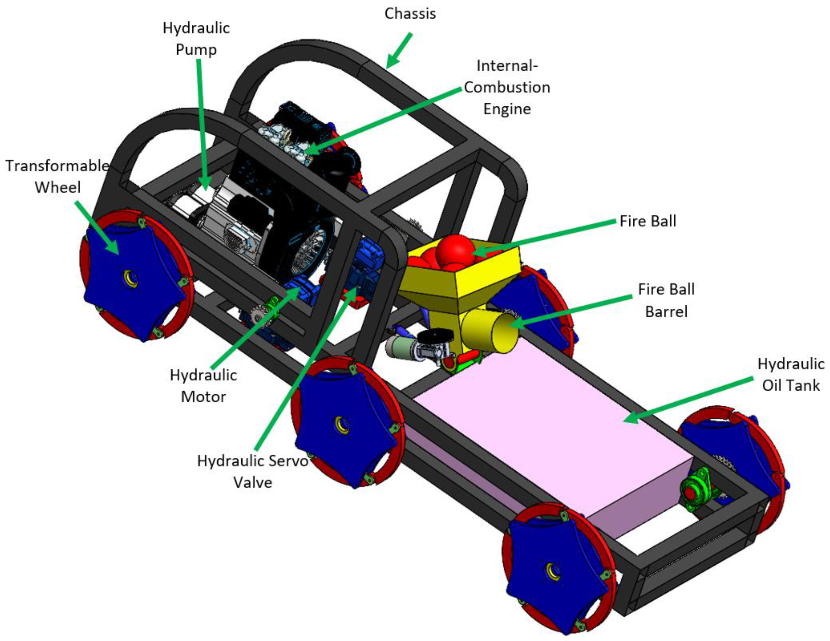
- ➢
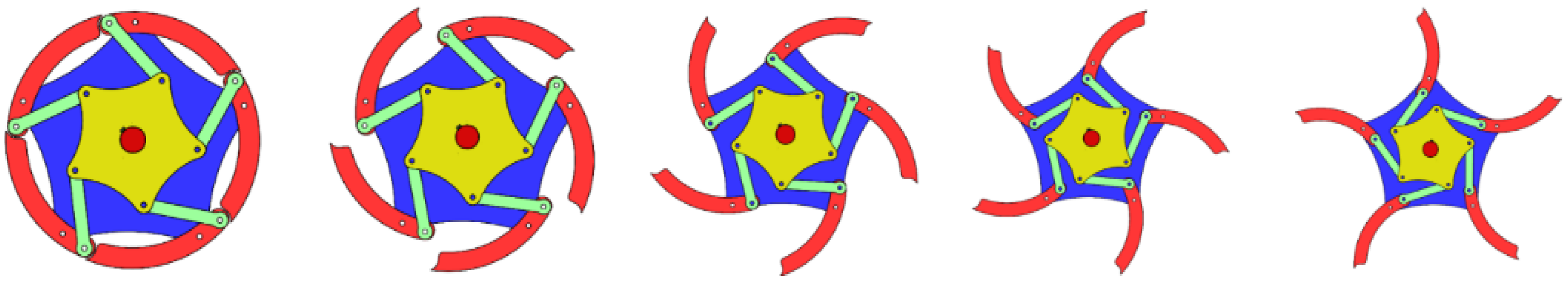
- The robot’s wheels will allow it to move fast over level ground.
- ➢
- The wheel construction will transform into a finger structure and be able to ascend the step-like obstruction.
- ➢
- There is a 2 DoF shooting turret on the robot. The turret throws a 1.3 kg fire extinguisher ball.
- ➢
- A shooting stabilization controller was developed to improve the hit rate of fire extinguishing balls.
- ➢
- The range of fire intervention has been increased to 85 m.
- ➢
- A hybrid firefighting robot with a transformable wheeled shooting turret’s kinematics and MATLAB/Simscape models were created.
- ➢
- PID and SMC controller were designed for turret stabilization of the 2 DoF shooting turret.
- ➢
- For three different motion scenarios (while the robot is standing and the robot is in motion, while the robot is turning to the right), fire extinguishing ball throws were executed at the fire zone at different heights and horizontal distances, and hit achievements were presented.
2. Materials and Methods
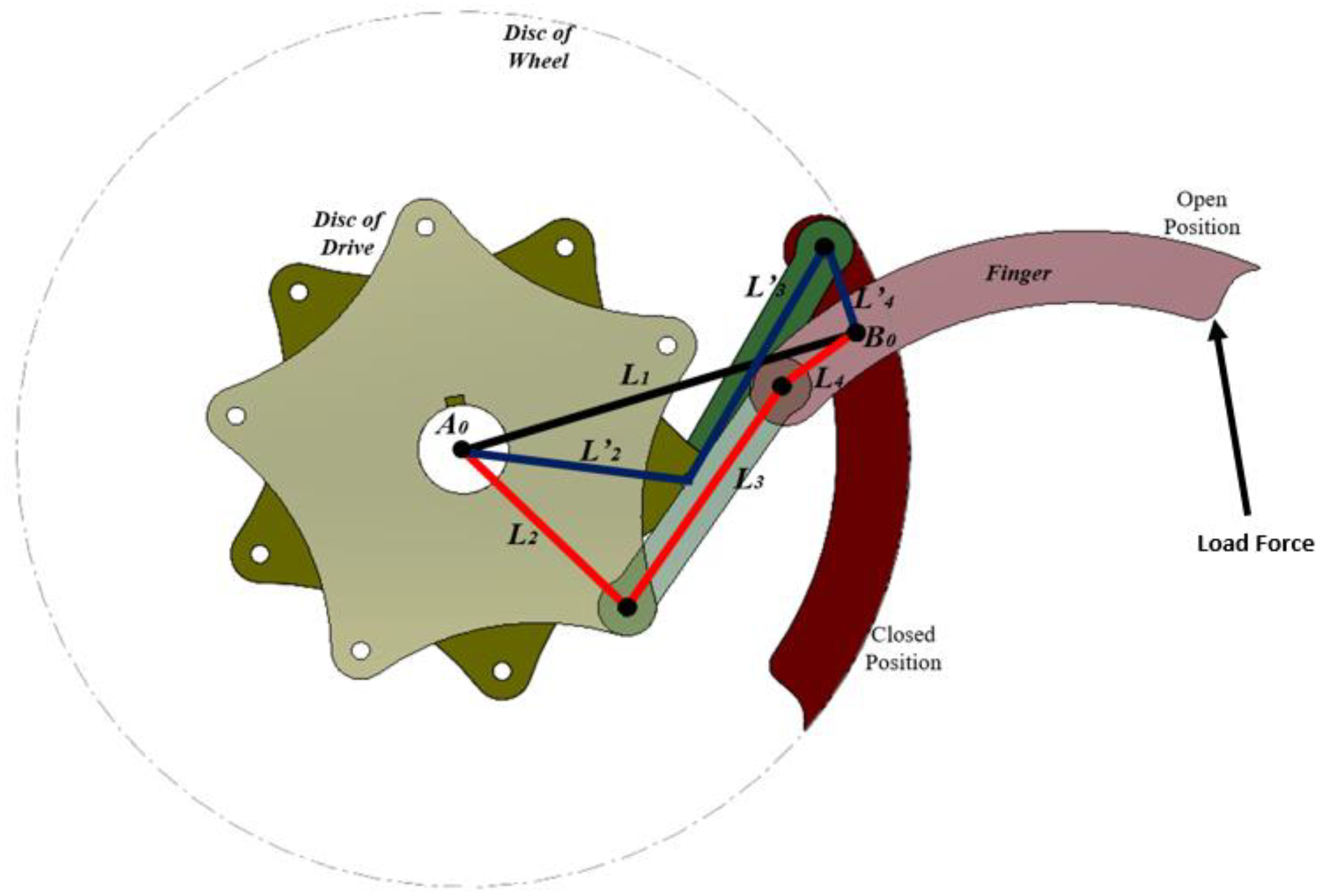
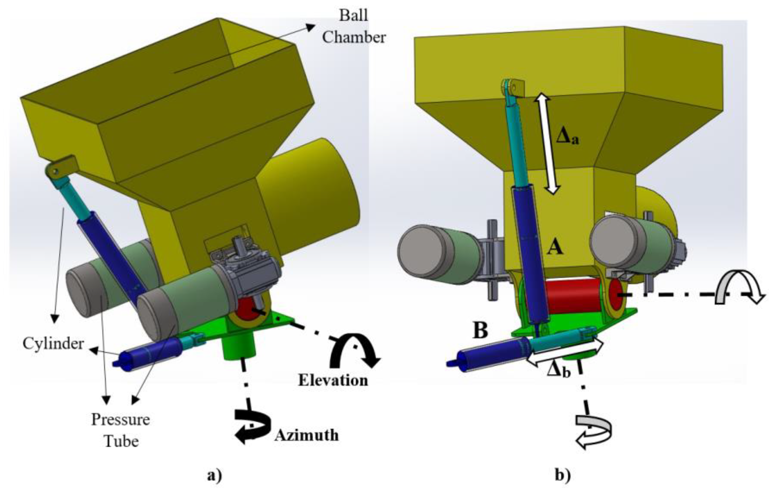
2.1. Transformable Wheeled Fire Fighting Robot with Fire Extinguishing Ball Controllersstem
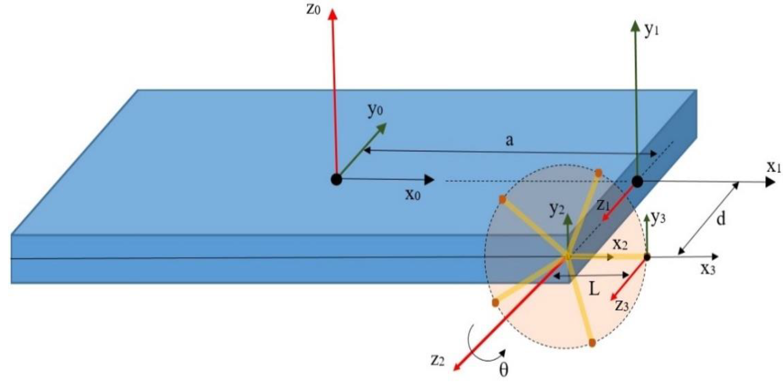
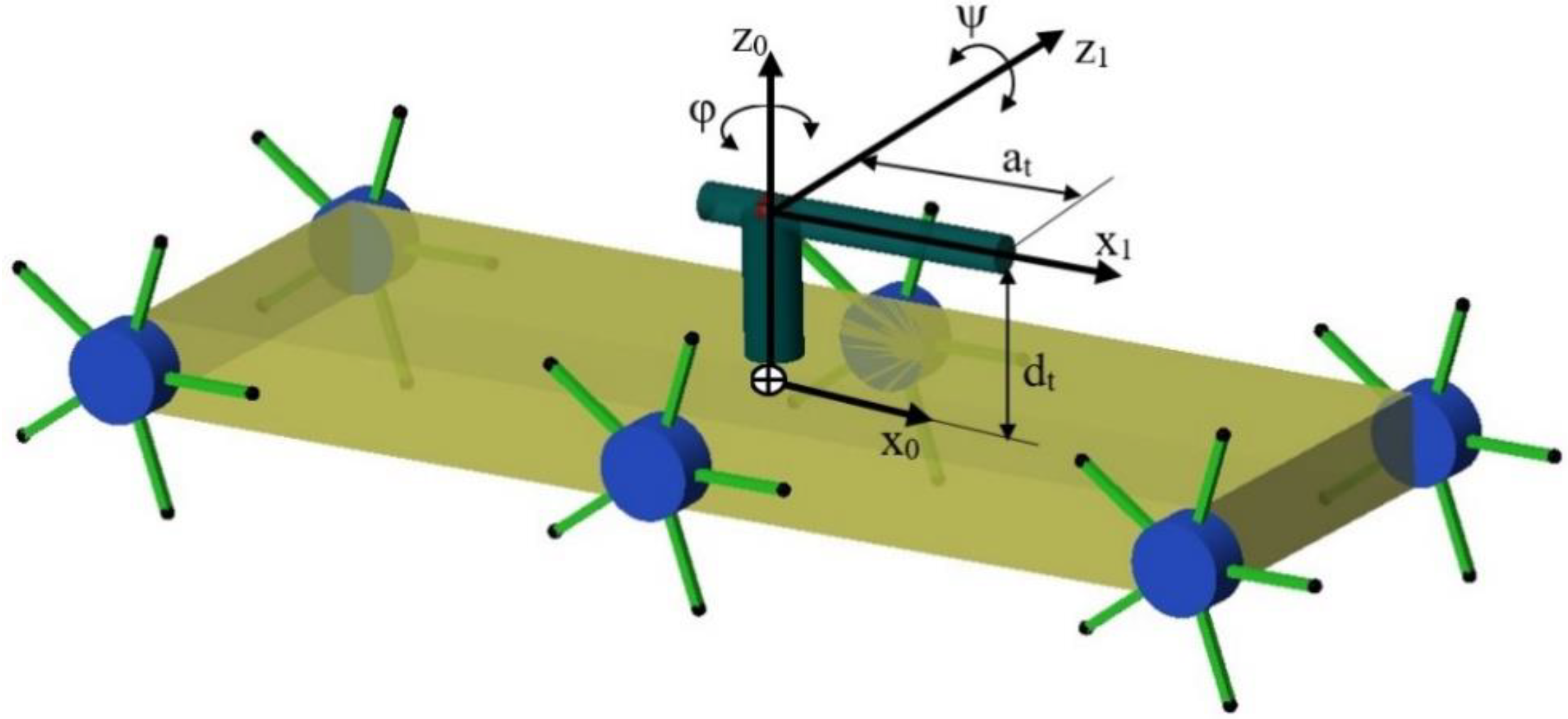
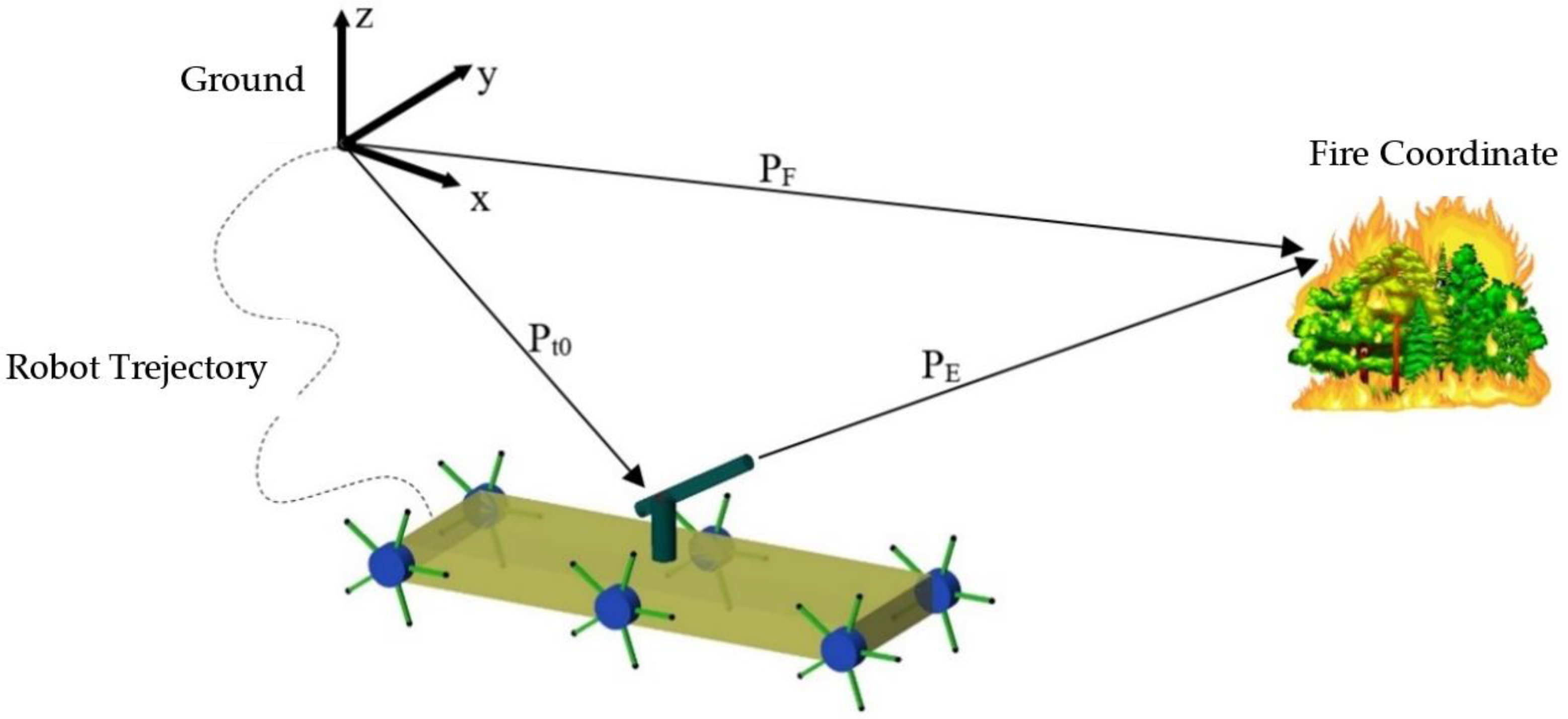
2.2. Mathematical Modeling of Transformable Wheeled Fire Fighting Robot
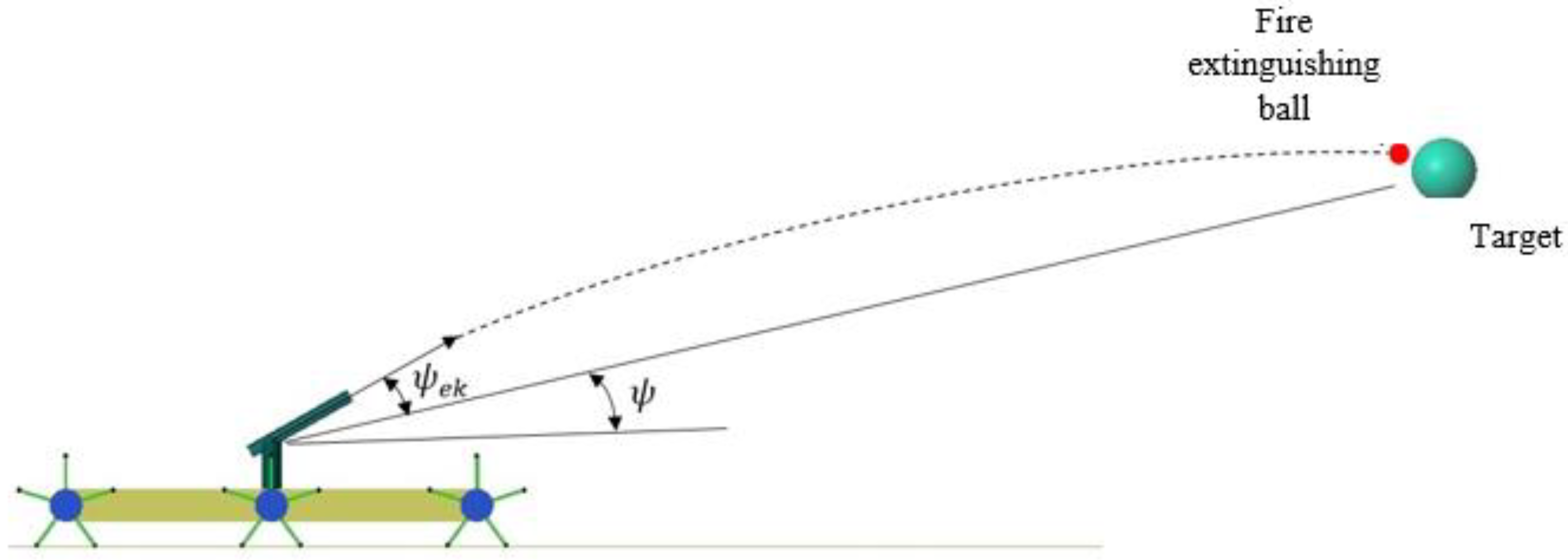
2.3. Mathematical Modeling of Fire Extinguishing Ball Shooting Turret System
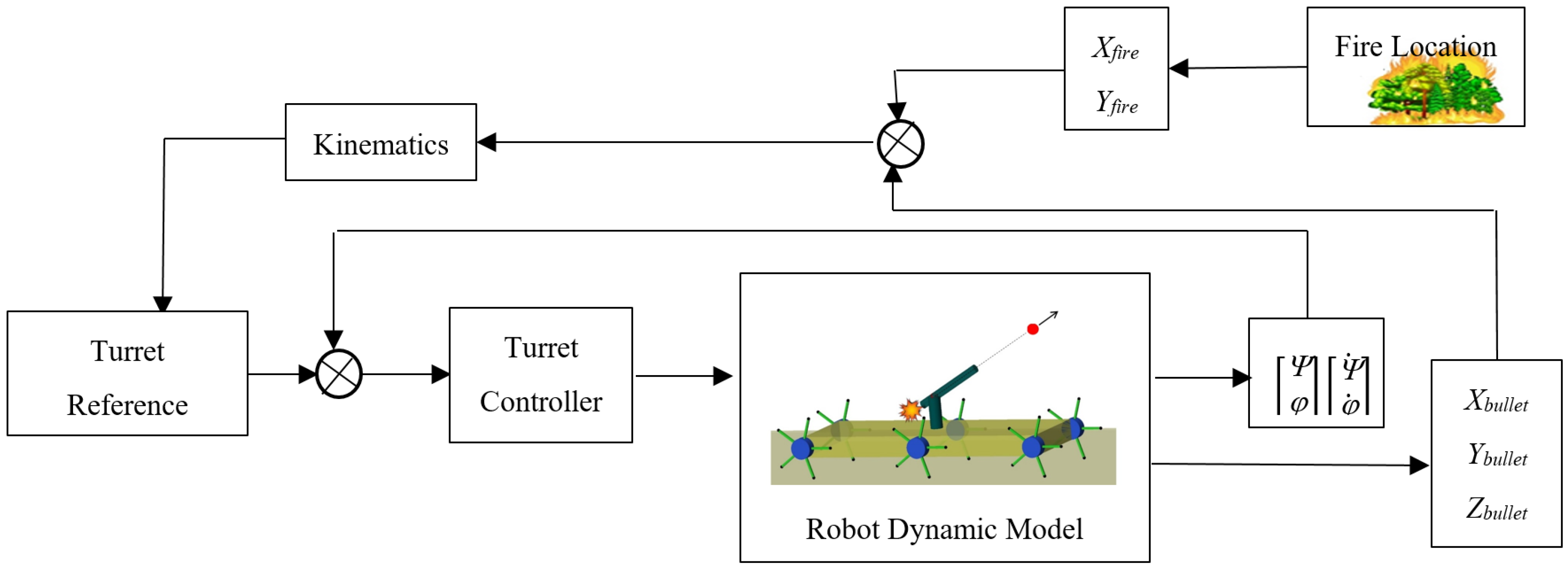
2.4. Control of Turret System
2.4.1. PID Controller Design
2.4.2. SMC Controller Design
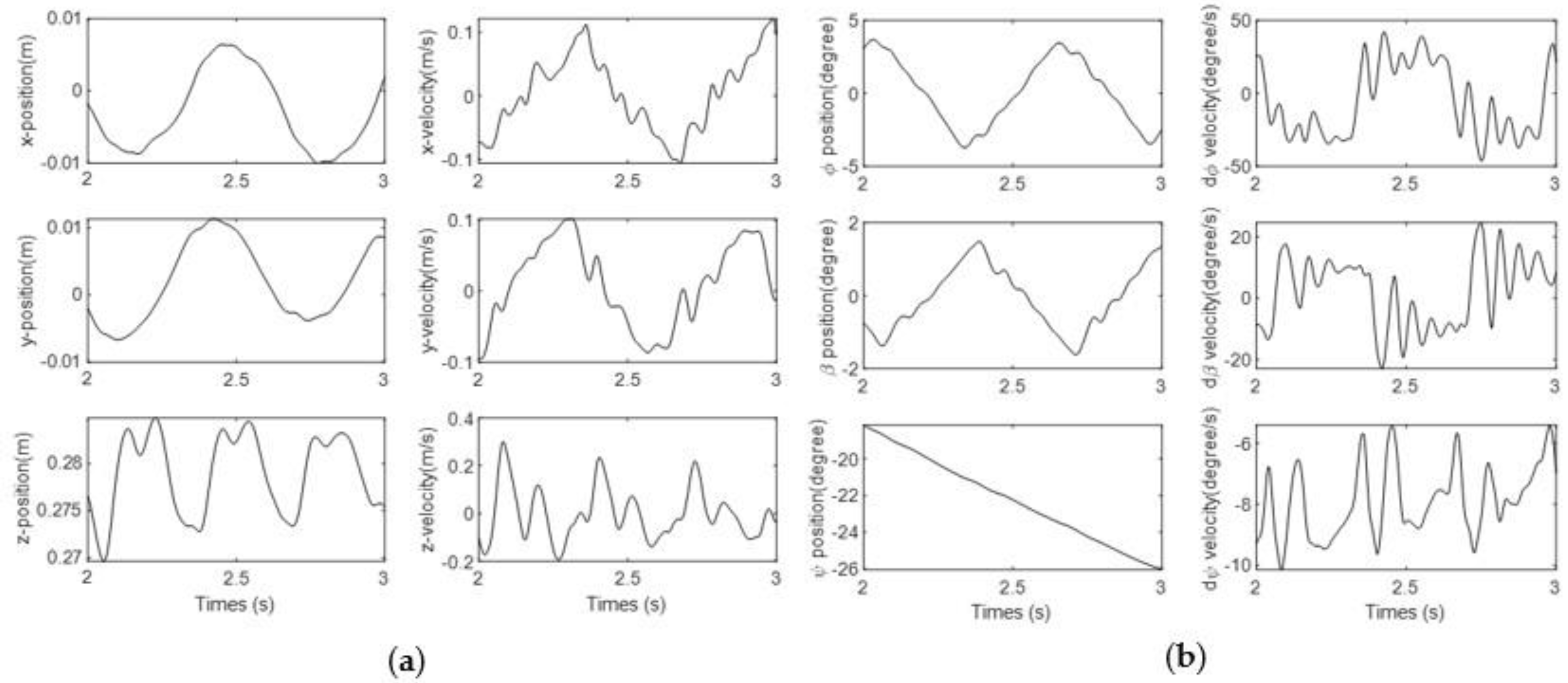
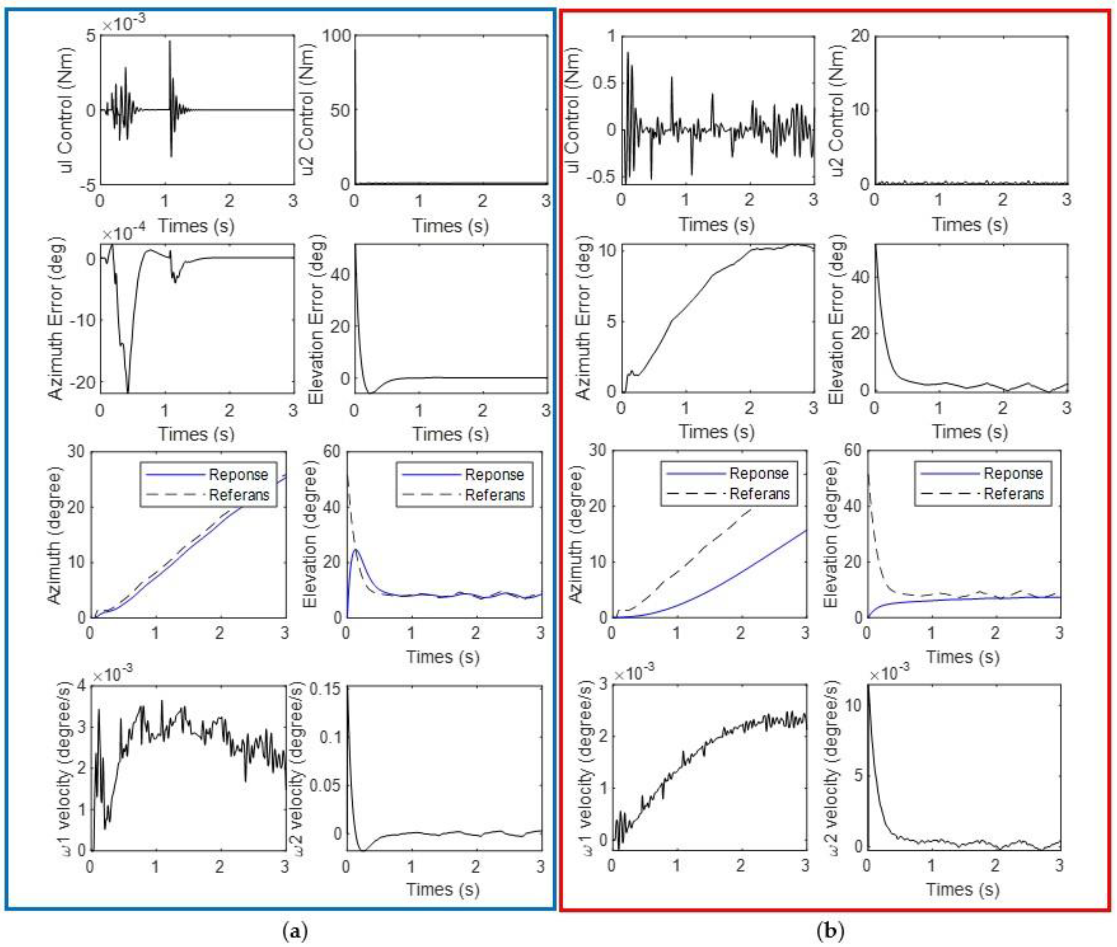
3. Simulation Setup and Results
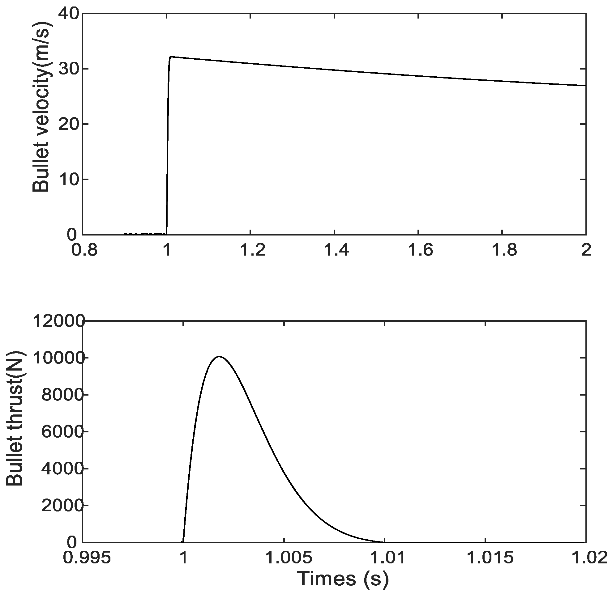
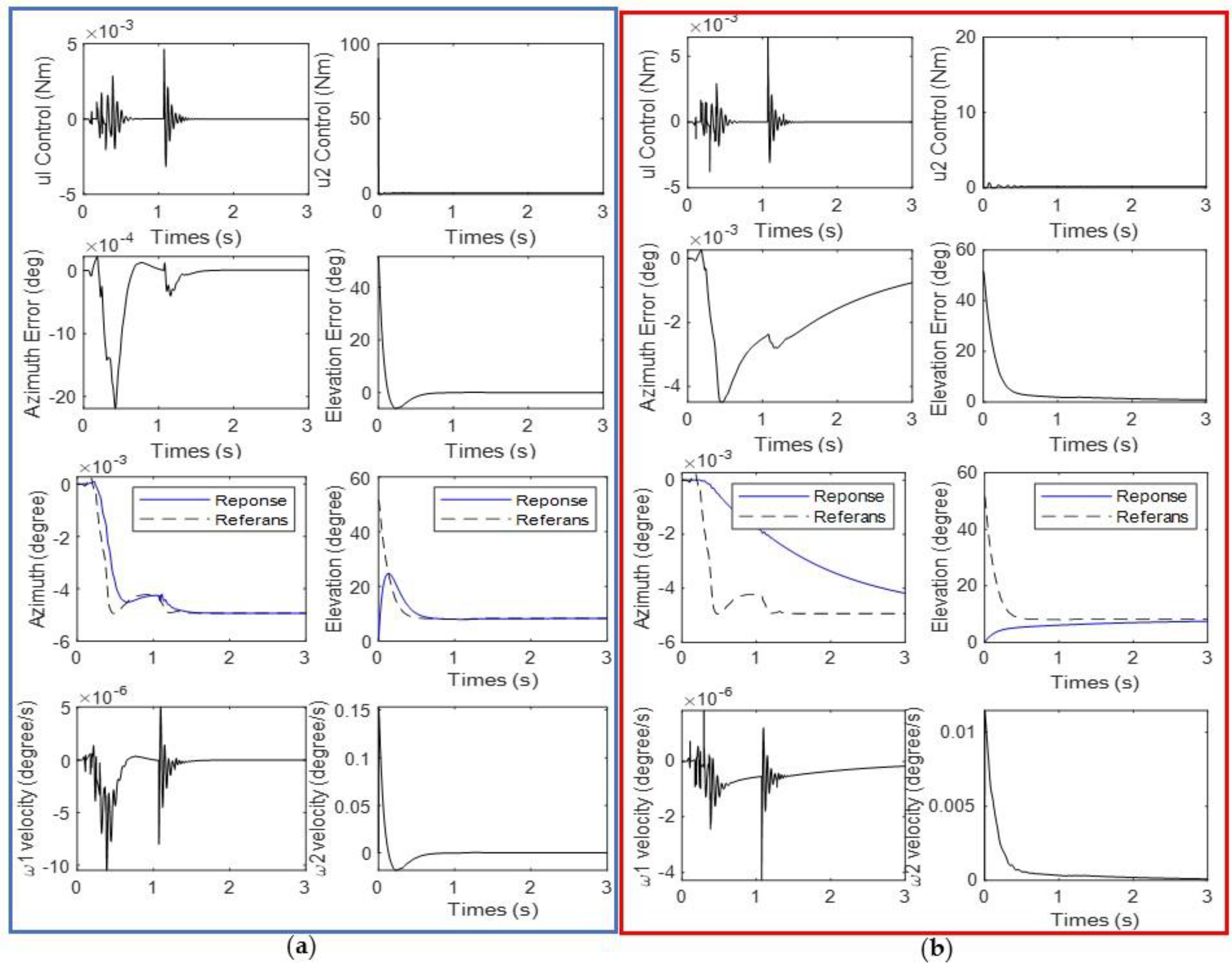
3.1. Results of Scenario 1: Shooting Fire Extinguishing Ball While Robot Standing
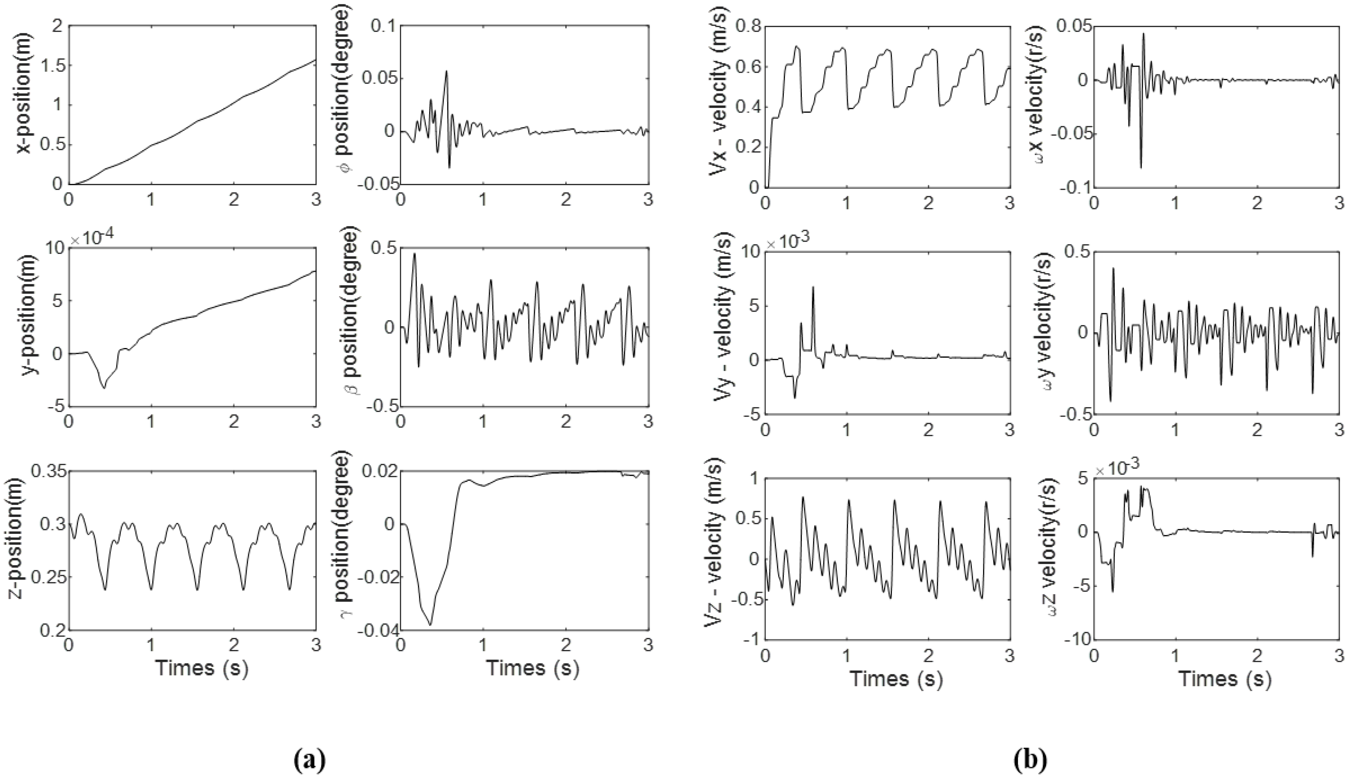
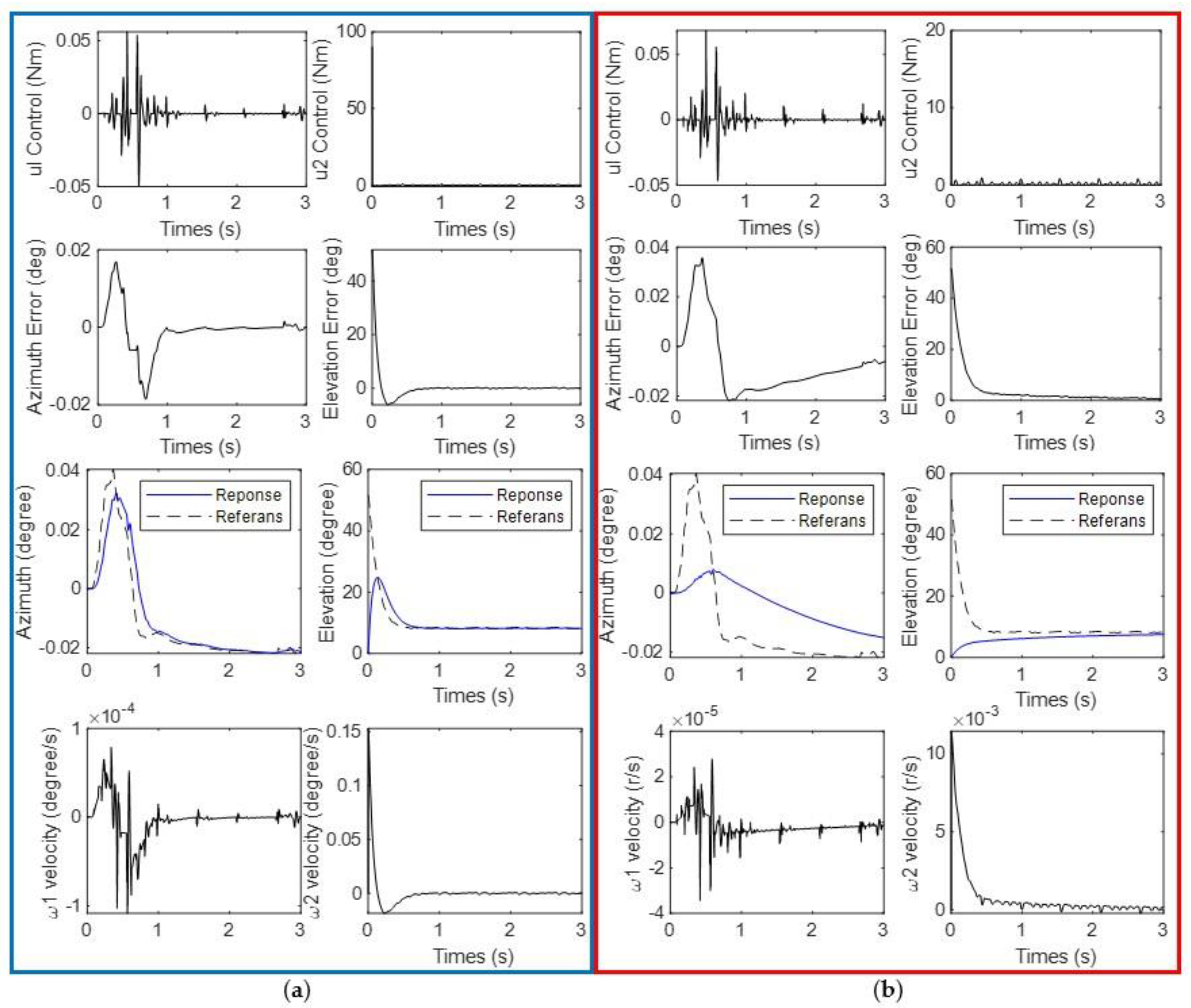
3.2. Results of Scenario 2: Shooting Fire While Going Straight
3.3. Results of Scenario 3: Shooting Fire While
4. Discussion
- ➢
- In the shooting simulation, the transformable wheeled robot struck 41 of the 105 targets with less than 1% error and 49 with a maximum error of 5% using the PID controller. Fifteen shots had an error rate greater than 5% and were judged unsuccessful.
- ➢
- Using the SMC controller, the transformable wheeled robot hit 42 of the 105 targets with an error of less than 1% and 56 with a maximum error of 5% in its shooting simulation. Seven of its shots had an error rate of more than 5% and were deemed unsuccessful.
5. Conclusions
6. Future Works
Funding
Data Availability Statement
Acknowledgments
Conflicts of Interest
References
- Avci, M.; Korkmaz, M. Türkiye’de orman yangını sorunu: Güncel bazı konular üzerine değerlendirmeler. Turk. J. For. 2020, 22, 229–240. [Google Scholar] [CrossRef]
- TOD, Success in Fighting Forest Fires, Gaining Public Trust and Ensuring Work and Life Safety of Personnel, Turkish Foresters Association (TOD) Press Release. 2020, pp. 1–8. Available online: https://www.ormancilardernegi.org/Documents/d3bb64d5-0f58-4449-81de-5e9dc1b9436c.pdf (accessed on 30 January 2023).
- Bogue, R. The role of robots in firefighting. Ind. Robot. Int. J. Robot. Res. Appl. 2021, 48, 174–178. [Google Scholar] [CrossRef]
- Campanharo, W.A.; Lopes, A.P.; Anderson, L.O.; da Silva, T.F.M.R.; Aragão, L.E.O.C. Translating fire impacts in Southwestern Amazonia into economic costs. Remote Sens. 2019, 11, 764. [Google Scholar] [CrossRef]
- Kang, R.; Fu, G.; Yan, J. Analysis of the Case of Fire Fighters Casualties in the Building Collapse. Procedia Eng. 2016, 135, 343–348. [Google Scholar] [CrossRef]
- Oliveira, L.F.P.; Moreira, A.P.; Silva, M.F. Advances in Forest Robotics: A State-of-the-Art Survey. Robotics 2021, 10, 53. [Google Scholar] [CrossRef]
- Mass, C.F.; Ovens, D. The Northern California Wildfires of 8–9 October 2017: The Role of a Major Downslope Wind Event. Bull. Am. Meteorol. Soc. 2019, 100, 235–256. [Google Scholar] [CrossRef]
- Wang, Y.; Xing, J.-P.; Guo, H.; Wang, L.-J. Key Technologies of Tunnel Firefighting Robots. IETE Tech. Rev. 2016, 34, 3–10. [Google Scholar] [CrossRef]
- Tan, G.W.M.R.C.F.; Liew, S.M.; Alkahari, M.R.; Ranjit, S.S.S.; Said, M.R.; Chen, W. Fire Fighting Mobile Robot: State of the Art and Recent Development. Aust. J. Basic Appl. Sci. 2013, 7, 220–230. [Google Scholar]
- Zhang, J.; Jin, Z.; Zhao, Y. Dynamics analysis of leg mechanism of six-legged firefighting robot. J. Mech. Sci. Technol. 2018, 32, 351–361. [Google Scholar] [CrossRef]
- Guo, A.; Jiang, T.; Li, J.; Cui, Y.; Li, J.; Chen, Z. Design of a small wheel-foot hybrid firefighting robot for infrared visual fire recognition. Mech. Based Des. Struct. Mach. 2021, 1–20. [Google Scholar] [CrossRef]
- Li, S.; Feng, C.; Niu, Y.; Shi, L.; Wu, Z.; Song, H. A Fire Reconnaissance Robot Based on SLAM Position, Thermal Imaging Technologies, and AR Display. Sensors 2019, 19, 5036. [Google Scholar] [CrossRef]
- Li, J.; Wang, J.; Peng, H.; Hu, Y.; Su, H. Fuzzy-Torque Approximation-Enhanced Sliding Mode Control for Lateral Stability of Mobile Robot. IEEE Trans. Syst. Man, Cybern. Syst. 2021, 52, 2491–2500. [Google Scholar] [CrossRef]
- Aliff, M.; Samsiah, N.; Yusof, M.; Zainal, A. Development of Fire Fighting Robot (QRob). Int. J. Adv. Comput. Sci. Appl. 2019, 10, 142–147. [Google Scholar] [CrossRef]
- Ando, H.; Ambe, Y.; Ishii, A.; Konyo, M.; Tadakuma, K.; Maruyama, S.; Tadokoro, S. Aerial Hose Type Robot by Water Jet for Fire Fighting. IEEE Robot. Autom. Lett. 2018, 3, 1128–1135. [Google Scholar] [CrossRef]
- McNeil, J.G.; Lattimer, B.Y. Robotic Fire Suppression Through Autonomous Feedback Control. Fire Technol. 2016, 53, 1171–1199. [Google Scholar] [CrossRef]
- Zhu, J.; Li, W.; Lin, D.; Cheng, H.; Zhao, G. Intelligent Fire Monitor for Fire Robot Based on Infrared Image Feedback Control. Fire Technol. 2020, 56, 2089–2109. [Google Scholar] [CrossRef]
- Jiang, H. Mobile Fire Evacuation System for Large Public Buildings Based on Artificial Intelligence and IoT. IEEE Access 2019, 7, 64101–64109. [Google Scholar] [CrossRef]
- Chen, Z.; Wang, S.; Wang, J.; Xu, K.; Lei, T.; Zhang, H.; Wang, X.; Liu, D.; Si, J. Control strategy of stable walking for a hexapod wheel-legged robot. ISA Trans. 2020, 108, 367–380. [Google Scholar] [CrossRef] [PubMed]
- Kim, J.-H.; Starr, J.W.; Lattimer, B.Y. Firefighting Robot Stereo Infrared Vision and Radar Sensor Fusion for Imaging through Smoke. Fire Technol. 2014, 51, 823–845. [Google Scholar] [CrossRef]
- Kim, J.-H.; Lattimer, B.Y. Real-time probabilistic classification of fire and smoke using thermal imagery for intelligent firefighting robot. Fire Saf. J. 2015, 72, 40–49. [Google Scholar] [CrossRef]
- Kim, J.; Kim, B.K. Cornering Trajectory Planning Avoiding Slip for Differential-Wheeled Mobile Robots. IEEE Trans. Ind. Electron. 2019, 67, 6698–6708. [Google Scholar] [CrossRef]
- Pransky, J. Geoff Howe, senior vice president, Howe and Howe, Inc., a subsidiary of Textron Systems; co-pioneer of robotic firefighting technologies, including Thermite™ firefighting robots. Ind. Robot. Int. J. Robot. Res. Appl. 2021, 48, 169–173. [Google Scholar] [CrossRef]
- Statistics Sweden. Design Your Questions Right: How to Develop, Test, Evaluate and Improve Questionnaires 2004. Available online: http://www. scb. se/statistik/_publikationer/OV9999_2004A01_BR_X97OP0402.pdf. (accessed on 6 June 2020).
- Magirus, Magirus AirCore. 2019. Available online: https://www.magirusgroup.com/de/en/products/special-vehicles/aircore/ or https://www.magirusgroup.com/de/de/produkte/spezialfahrzeuge/aircore/ (accessed on 6 May 2022).
- Shark Robotics. Colossus. 2020. Available online: https://www.shark-robotics.com/shark-robots (accessed on 6 May 2022).
- Milrem Robotics, Multiscope Rescue with Hydra. 2020. Available online: https://milremrobotics.com/product/multiscope-rescue-hydra/ (accessed on 6 May 2022).
- Milrem Robotics, Multiscope Rescue Hose Cartridge. 2020. Available online: https://milremrobotics.com/product/firehouse-container/ (accessed on 6 May 2022).
- Župančić, I. Special robotized multipurpose vehicle DOK-ING MVF-5. Vatrog. I Upravlj. Požarima 2012, 2, 17–35. [Google Scholar]
- Apparatus, F. Firefighting Robotic Vehicle System. 2020. Available online: https://www.fireapparatusmagazine.com/fireapparatus/firefighting-robotic-vehicle-system/#gref (accessed on 6 May 2022).
- LUF. LUF60 Fire Frighter. 2019, p. 1. Available online: https://www.luf60.at/wp-content/uploads/sites/62/2019/07/luf_60_en.pdf (accessed on 30 January 2023).
- Ryland Research. Fire-Fighting Robotics. 2010. Available online: https://rylandresearch.com/research-and-development/fire-fighting-robotics/ (accessed on 30 January 2023).
- Zhao, J.; Zhang, Z.; Liu, S.; Tao, Y.; Liu, Y. Design and Research of an Articulated Tracked Firefighting Robot. Sensors 2022, 22, 5086. [Google Scholar] [CrossRef] [PubMed]
- Murph, D. ARMTEC’ s SACI firefighting robot. 2006. Available online: https://www.engadget.com/2006-08-03-armtecs-saci-firefighting-robot.html (accessed on 30 January 2023).
- Firefighting Robots. 2022. Available online: https://www.allonrobots.com/firefighting-robots/ (accessed on 30 January 2023).
- MyBOT-X. The First Malaysia Fire Fighting Robot. 2013. Available online: https://www.robolab.com.my/wp-content/uploads/2019/05/MyBOT-X-series_007_2018.pdf (accessed on 30 January 2023).
- VisitFinland, MHI Develops Autonomous ‘Water Cannon Robot’ and ‘Hose Extension Robot’ for Use in Firefighting—Expected to Play Active Role in Hazardous Situations Inaccessible to Firefighting Crews. 2019. Available online: https://www.mhi.com/news/190325.html (accessed on 30 January 2023).
- Debbie Sniderman, Robotic Firefighting Vehicles. 2011. Available online: ASME.org (accessed on 30 January 2023).
- Deliverable, S. Mobile Robots with Novel Environmental Sensors for Inspection of Disaster Sites with Low Visibility Software Toolkit. Data Vis. 2018, 40, 1–5. [Google Scholar]
- Dobric, J. SmokeBot—A Robot Serving Rescue Units. 2018. Available online: https://www.oru.se/english/news/news-archive/news-archive-2018/smokebot--a-robot-serving-rescue-units/ (accessed on 30 January 2023).
- Zhang, J.; Jin, Z.; Feng, H. Type synthesis of a 3-mixed-DOF protectable leg mechanism of a firefighting multi-legged robot based on GF set theory. Mech. Mach. Theory 2018, 130, 567–584. [Google Scholar] [CrossRef]
- Tatar, A.B.; Tanyıldızı, A.K.; Yakut, O. Four-legged hunter (FLH) robot: Design and shooting control to moving targets with SMC. Simul. Model. Pract. Theory 2020, 104, 102117. [Google Scholar] [CrossRef]
- Çakar, O.; Tanyıldızı, A.K. Application of moving sliding mode control for a DC motor driven four-bar mechanism. Adv. Mech. Eng. 2018, 10. [Google Scholar] [CrossRef]


| Part | Features | Values |
|---|---|---|
| Robot Dimensions | Height | 954.5 mm |
| Width | 1137.65 mm (including wheel)–800 mm (except wheel) | |
| Length | 2618 mm | |
| Weight | 582.5 kg | |
| Cannon (Turret) | Length | 700 mm |
| Location | Distance from front: 542.6 mm Distance from side: Right in the middle, 400 mm (excluding wheels) | |
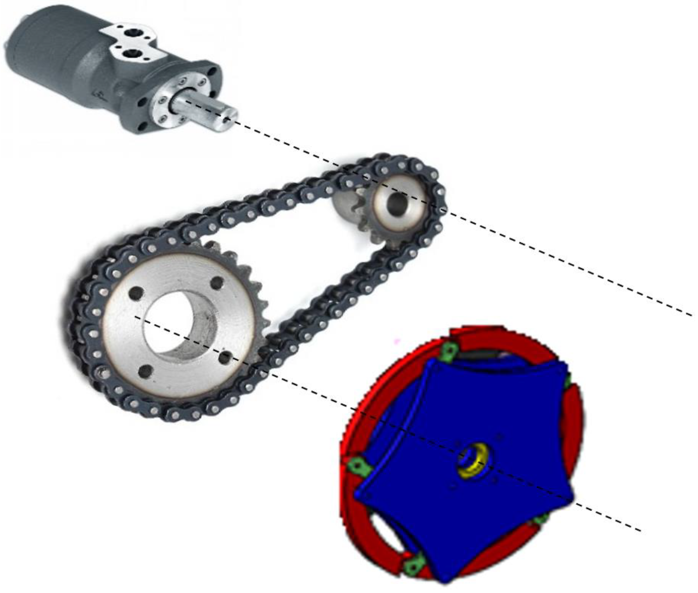
| Hydraulic Motor | Transfer | 810 rpm (cont.)–1000 rpm (int.) |
| Torque (int.) | 240 N·m (cont.)–310 N·m | |
| Weight | 12 kg | |
| Piece | Two. One drives the wheels on the left and the other those on the right. | |
| Power transmission mechanism | Power is transmitted by chain-gear on each side. | |
| Gear Reduction Ratio | 2/The diameter of the gears connected to the wheels is twice that of the gear connected to the hydraulic motors. | |
| Piston | Two move the two axes of the shooting turret. | |
| Hydraulic Pump | Piece | 4 (2 for hydraulic motors and the other for oil transmission to the cylinders of the fire turret shooting turret.) |
| Weight | 114 kg | |
| Working Pressure (int.) | 250 Bar (cont.)–280 Bar | |
| Flow | 26.70 cc/dev | |
| Servo valve | 4/The servo valve is used to precisely control the hydraulic oil flow. It is the unit that transfers the pressurized hydraulic oil from the pump to the engines in a controlled manner. | |
| Diesel Engine (with reducer) | Strength | 17 kW |
| Max. Torque | 50 N·m (2000 rpm) | |
| Weight | 106 kg | |
| Wheel Dimensions/speed/torque | Closed | 490 mm |
| Open | 900 mm | |
| Rotation Speed | 405 rpm (cont.)–500 rpm (int.) | |
| Torque | 480 N·m (cont.)–620 N·m (int.) | |
| Fire Extinguishing Ball Dimensions | Weight | 1.3 kg |
| Diameter | 14.5 cm | |
| Capacity | Load Capacity | 10 fire extinguishing ball |
| Link | θ | α | a | d |
|---|---|---|---|---|
| 1 | 0 | 90 | a | 0 |
| 2 | 0 | 0 | 0 | d |
| 3 | θ | 0 | L | 0 |
| Wheel | Position | Parameters | |
|---|---|---|---|
| 1 | Right-Front | a | +d |
| 2 | Left-Front | a | −d |
| 3 | Right Middle | a = 0 | +d |
| 4 | Left Middle | a = 0 | −d |
| 5 | Right-Rear | −a | +d |
| 6 | Left-Rear | −a | −d |
| Controller Type | Parameters |
|---|---|
| PID | :100, :10, :1 for azimuth and elevation joint |
| SMC | cazimuth = 0.731, celevation = 0.729, Ɛ = 0.001 Kazimuth = 29.98, Kelevation = 30.13 |
| Target Distance (m) | Target Height (m) | |||||||||
|---|---|---|---|---|---|---|---|---|---|---|
| 1 | 5 | 10 | 20 | 30 | ||||||
| PID | SMC | PID | SMC | PID | SMC | PID | SMC | PID | SMC | |
| 20 | 0.73 | 0.9454 | 0.85 | 0.7906 | 1.01 | 0.6036 | 1.43 | 0.2682 | 2.07 | 0.0126 |
| 30 | 0.59 | 0.9265 | 0.80 | 0.8004 | 1.03 | 0.6452 | 1.41 | 0.3520 | 1.70 | 0.0893 |
| 40 | 0.30 | 0.9029 | 0.60 | 0.7941 | 0.93 | 0.6591 | 1.40 | 0.3979 | 1.40 | 0.1545 |
| 50 | 0.10 | 0.8748 | 0.50 | 0.7775 | 0.92 | 0.6564 | 1.42 | 0.4189 | 0.87 | 0.1922 |
| 60 | 0.19 | 0.8417 | 0.66 | 0.7526 | 1.13 | 0.6414 | 1.36 | 0.4216 | 0.64 | 0.2083 |
| 70 | 0.68 | 0.8028 | 1.12 | 0.7197 | 1.41 | 0.6158 | 0.45 | 0.4090 | 4.92 | 0.2061 |
| 80 | 1.25 | 0.7573 | 1.32 | 0.6785 | 0.81 | 0.5798 | 3.53 | 0.3826 | 15.07 | 0.1872 |
| Target Distance (m) | Target Height (m) | |||||||||
|---|---|---|---|---|---|---|---|---|---|---|
| 1 | 5 | 10 | 20 | 30 | ||||||
| PID | SMC | PID | SMC | PID | SMC | PID | SMC | PID | SMC | |
| 20 | 0.50 | 0.7217 | 0.68 | 0.5727 | 10 | 0.3929 | 1.39 | 0.0777 | 2.05 | 0.2067 |
| 30 | 0.18 | 0.7034 | 0.44 | 0.5820 | 0.90 | 0.4327 | 1.16 | 0.1532 | 1.43 | 0.1118 |
| 40 | 0.28 | 0.6807 | 0.04 | 0.5759 | 0.72 | 0.4460 | 0.91 | 0.1963 | 0.81 | 0.0570 |
| 50 | 0.68 | 0.6536 | 0.27 | 0.5599 | 0.41 | 0.4434 | 0.65 | 0.2162 | 0.10 | 0.0388 |
| 60 | 0.81 | 0.6217 | 0.32 | 0.5359 | 0.17 | 0.4290 | 0.26 | 0.2187 | 2.04 | 0.0395 |
| 70 | 0.54 | 0.5843 | 0.13 | 0.5043 | 0.12 | 0.4044 | 1.01 | 0.2086 | 6.70 | 0.0391 |
| 80 | 0.24 | 0.5405 | 0.22 | 0.4647 | 0.11 | 0.3699 | 5.32 | 0.1818 | 17.08 | 0.0398 |
| Target Distance (m) | Target Height (m) | |||||||||
|---|---|---|---|---|---|---|---|---|---|---|
| 1 | 5 | 10 | 20 | 30 | ||||||
| PID | SMC | PID | SMC | PID | SMC | PID | SMC | PID | SMC | |
| 20 | 0.43 | 1.7386 | 0.63 | 1.6558 | 10 | 1.5700 | 1.59 | 1.4619 | 2.52 | 1.4244 |
| 30 | 0.10 | 1.7287 | 0.40 | 1.6613 | 0.91 | 1.5880 | 1.46 | 1.4830 | 2.19 | 1.4323 |
| 40 | 0.42 | 1.7163 | 0.32 | 1.6588 | 0.76 | 1.5947 | 1.40 | 1.4969 | 2.10 | 1.4415 |
| 50 | 0.86 | 1.7018 | 0.61 | 1.6513 | 0.63 | 1.5944 | 1.49 | 1.5043 | 2.33 | 1.4487 |
| 60 | 1.05 | 1.6058 | 0.82 | 1.6400 | 0.73 | 1.5888 | 1.79 | 1.5062 | 3.47 | 1.4529 |
| 70 | 1.01 | 1.6660 | 1.05 | 1.6253 | 0.99 | 1.5790 | 2.60 | 1.5036 | 7.38 | 1.4540 |
| 80 | 1.28 | 1.6645 | 1.62 | 1.6075 | 1.41 | 1.5655 | 6.14 | 1.4972 | 17.18 | 1.4525 |
| Metrics | Turret Axes | Scenario 1 | Scenario2 | Scenario 3 | |||
|---|---|---|---|---|---|---|---|
| PID | SMC | PID | SMC | PID | SMC | ||
| Max. steady-state tracking error (degree) | Azimuth | 0.0002 | 0.0001 | 0.035 | 0.0167 | 10.42 | 1.179 |
| Elevation | 1.78 | 0.172 | 1.4 | 0.193 | 2.53 | 0.019 | |
| No | Target Distance and Height (m) | Total Distance (m) | The Percentage Firing Fault of Hit/Firing Accuracy Value Scenario 1 | The Percentage Firing Fault of Hit/Firing Accuracy Value Scenario 2 | The Percentage Firing Fault of Hit/Firing Accuracy Value Scenario 3 | |||
|---|---|---|---|---|---|---|---|---|
| Controller Type | PID | SMC | PID | SMC | PID | SMC | ||
| 1 | 20 m/1 m | 20.024 | 3.645625 | 4.721334 | 2.497004 | 3.604175 | 2.147423 | 8.682581 |
| 2 | 20 m/5 m | 20.615 | 4.123211 | 3.835072 | 3.298569 | 2.778074 | 3.056027 | 8.032016 |
| 3 | 20 m/10 m | 22.360 | 4.516995 | 2.699463 | 4.025045 | 1.757156 | 4.069767 | 7.021467 |
| 4 | 20 m/20 m | 28.284 | 5.055862 | 0.948239 | 4.914439 | 0.274714 | 5.621553 | 5.168647 |
| 5 | 20 m/30 m | 36.055 | 5.741229 | 0.034947 | 5.685758 | 0.573291 | 6.989322 | 3.950631 |
| 6 | 30 m/1 m | 30.016 | 1.965618 | 3.086687 | 0.59968 | 2.343417 | 0.333156 | 5.759262 |
| 7 | 30 m/5 m | 30.413 | 2.630454 | 2.631769 | 1.44675 | 1.913655 | 1.315227 | 5.462467 |
| 8 | 30 m/10 m | 31.622 | 3.257226 | 2.040352 | 2.276896 | 1.368351 | 2.40339 | 5.02182 |
| 9 | 30 m/20 m | 36.055 | 3.910692 | 0.976286 | 3.217307 | 0.424906 | 4.049369 | 4.11316 |
| 10 | 30 m/30 m | 42.426 | 4.006977 | 0.210484 | 3.370575 | 0.263518 | 5.161929 | 3.375996 |
| 11 | 40 m/1 m | 40.012 | 0.749775 | 2.256573 | 0.69979 | 1.70124 | 1.049685 | 4.289463 |
| 12 | 40 m/5 m | 40.311 | 1.488427 | 1.969934 | 0.099228 | 1.428642 | 0.793828 | 4.115006 |
| 13 | 40 m/10 m | 41.231 | 2.255584 | 1.598554 | 0.994397 | 1.08171 | 1.527977 | 3.867721 |
| 14 | 40 m/20 m | 44.721 | 3.13052 | 0.889739 | 2.034838 | 0.438944 | 3.13052 | 3.347197 |
| 15 | 40 m/30 m | 50 | 2.8 | 0.309 | 1.62 | 0.114 | 4.2 | 2.883 |
| 16 | 50 m/1 m | 50.009 | 0.199964 | 1.749285 | 1.359755 | 1.306965 | 1.71969 | 3.402987 |
| 17 | 50 m/5 m | 50.249 | 0.995045 | 1.547294 | 0.537324 | 1.114251 | 1.213955 | 3.286235 |
| 18 | 50 m/10 m | 50.990 | 1.804275 | 1.287311 | 0.333399 | 0.869582 | 1.431653 | 3.126888 |
| 19 | 50 m/20 m | 53.851 | 2.636906 | 0.777887 | 1.207034 | 0.401478 | 2.766894 | 2.793449 |
| 20 | 50 m/30 m | 58.309 | 1.492051 | 0.329623 | 0.1715 | 0.066542 | 3.995953 | 2.484522 |
| 21 | 60 m/1 m | 60.008 | 0.316624 | 1.402646 | 1.34982 | 1.036029 | 1.749767 | 2.675977 |
| 22 | 60 m/5 m | 60.207 | 1.096218 | 1.250021 | 0.5315 | 0.890096 | 1.361968 | 2.723936 |
| 23 | 60 m/10 m | 60.827 | 1.857728 | 1.054466 | 0.197281 | 0.705279 | 1.627567 | 2.611998 |
| 24 | 60 m/20 m | 63.245 | 2.150368 | 0.666614 | 0.4111 | 0.345798 | 2.830263 | 2.381532 |
| 25 | 60 m/30 m | 67.082 | 0.954056 | 0.310515 | 3.041054 | 0.058883 | 5.172774 | 2.165857 |
| 26 | 70 m/1 m | 70.007 | 0.971331 | 1.146742 | 0.771351 | 0.834631 | 1.442713 | 2.379762 |
| 27 | 70 m/5 m | 70.178 | 1.595942 | 1.025535 | 0.185243 | 0.718601 | 1.496195 | 2.315968 |
| 28 | 70 m/10 m | 70.710 | 1.99406 | 0.870881 | 0.155565 | 0.571913 | 1.99406 | 2.233065 |
| 29 | 70 m/20 m | 72.801 | 0.618123 | 0.561805 | 1.387344 | 0.286535 | 3.57138 | 2.065356 |
| 30 | 70 m/30 m | 76.157 | 6.460339 | 0.270625 | 8.797615 | 0.051341 | 9.690508 | 1.909214 |
| 31 | 80 m/1 m | 80.006 | 1.562383 | 0.946554 | 0.299978 | 0.675574 | 1.59988 | 2.080469 |
| 32 | 80 m/5 m | 80.156 | 1.646789 | 0.846474 | 0.274465 | 0.579744 | 2.021059 | 2.005464 |
| 33 | 80 m/10 m | 80.622 | 1.004689 | 0.719159 | 1.004689 | 0.458808 | 2.790802 | 1.941778 |
| 34 | 80 m/20 m | 82.462 | 4.28076 | 0.463971 | 6.451456 | 0.220465 | 7.445854 | 1.815624 |
| 35 | 80 m/30 m | 85.440 | 17.63811 | 0.219101 | 19.99064 | 0.046582 | 20.10768 | 1.700023 |
Disclaimer/Publisher’s Note: The statements, opinions and data contained in all publications are solely those of the individual author(s) and contributor(s) and not of MDPI and/or the editor(s). MDPI and/or the editor(s) disclaim responsibility for any injury to people or property resulting from any ideas, methods, instructions or products referred to in the content. |
© 2023 by the author. Licensee MDPI, Basel, Switzerland. This article is an open access article distributed under the terms and conditions of the Creative Commons Attribution (CC BY) license (https://creativecommons.org/licenses/by/4.0/).
Share and Cite
Tanyıldızı, A.K. Design, Control and Stabilization of a Transformable Wheeled Fire Fighting Robot with a Fire-Extinguishing, Ball-Shooting Turret. Machines 2023, 11, 492. https://doi.org/10.3390/machines11040492
Tanyıldızı AK. Design, Control and Stabilization of a Transformable Wheeled Fire Fighting Robot with a Fire-Extinguishing, Ball-Shooting Turret. Machines. 2023; 11(4):492. https://doi.org/10.3390/machines11040492
Chicago/Turabian StyleTanyıldızı, Alper Kadir. 2023. "Design, Control and Stabilization of a Transformable Wheeled Fire Fighting Robot with a Fire-Extinguishing, Ball-Shooting Turret" Machines 11, no. 4: 492. https://doi.org/10.3390/machines11040492