1. Introduction
There is an increasing demand in the oil and gas industry to improve efficiency of well drilling in medium-hard rocks. Processes of drilling and completion of the oil and gas wells face severe challenges, including great burial depth, large formation dip and steepness, narrow pressure window, poor drillability of the rocks, thick gravel layer, salt bed and other complex strata intervals, which often result in complex accidents, high temperature, high pressure, high acidity and other impediments [
1,
2]. Speight [
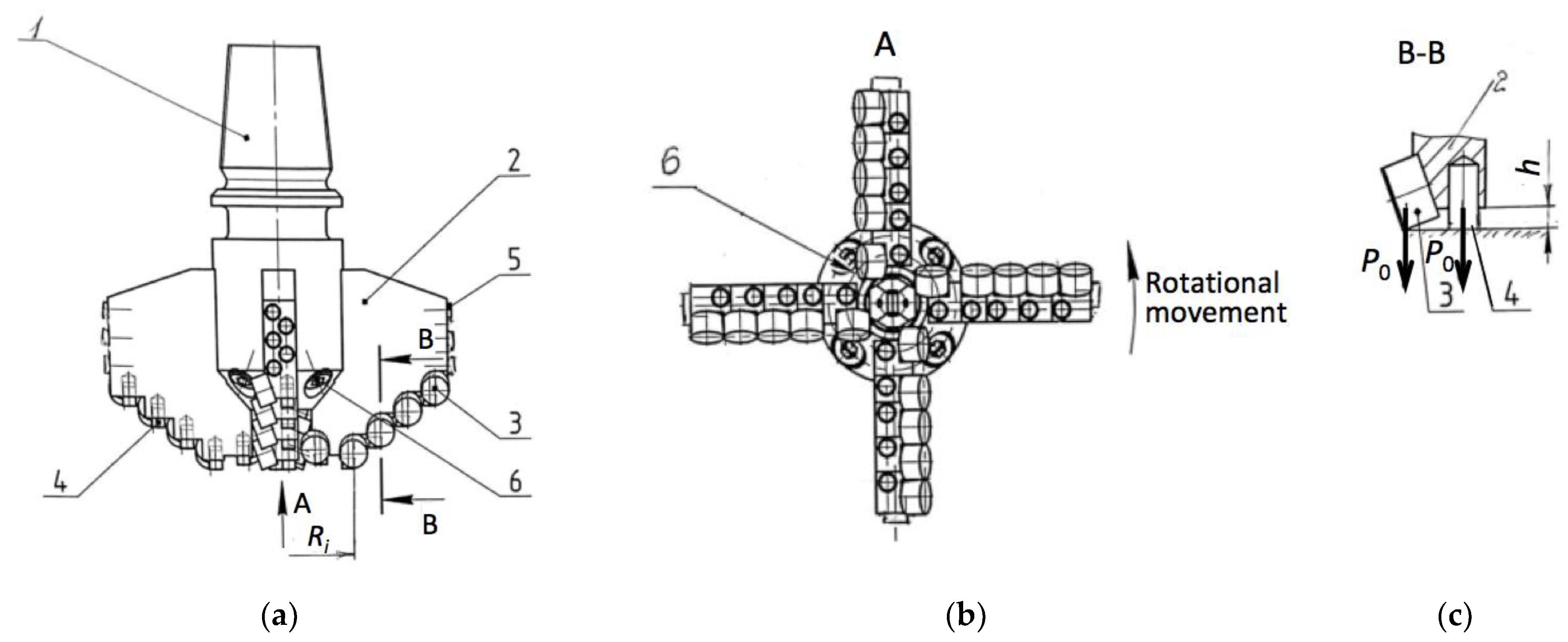
3] emphasized that usually in the oil and gas mining, the roller-cone drill bits are used. They may have three roller cones with teeth, as shown in
Figure 1, but one, two, or four can also be used. Their design makes it possible to crush the rock by indentation and a gouging action when the cones of the bit roll across the bottom. The indentation of teeth against the rock takes place with pressure exceeding its strength. Thus, the rock fracture occurs. In the so-called “non inserts” bit, the teeth on each cone are made of the same piece of metal as the bit. Alternatively, they can be fabricated in the form of inserts that are harder and more durable than the metal teeth. The tooth wedge can be formed either sharp or flat. The rolling cones are supported by bearings, and the bearing axis forms the cone-journal angle [
3].
Speight [
3] also describes the natural diamond bits, which are constructed using diamonds embedded into a matrix. These may be used in coring operations, conventional rotary, and turbine. Compared to roller bits, diamond bits can reach improved drilling rates in some formations. Usually, the diamond bits are supplied with comparison tables showing the performance of roller-cone and diamond bits to allow for economic evaluation in bit selection. Among the benefits of diamond bits, Speight [
3] listed:
Lack of moving parts and thus reduced failure potential;
Reduced drilling effort required for the shearing action, compared to the cracking and grinding processes implemented by the roller bit;
Reduced bit weight and thus improved deviation control;
Suitability for turbine drilling.
The polycrystalline diamond compact (PDC) bit is the drilling tool most commonly used to create a passage for oil and gas exploration through the rock from the ground to the bottomhole [
4]. Keeping in mind that due to high rock-breaking efficiency of PDC bits, they contribute to more than 90% of total drilling length throughout the world [
5], any additional study on their improvement is desirable.
The design and implementation of compact bits equipped with polycrystalline diamond-reinforced composite cutting inserts made it possible to dramatically increase the speed of drilling. Moreover, penetration per tool was significantly increased. According to the data collected in [
6], at the large oil and gas field Uzen in Kazakhstan, the replacement of traditional cone bits with PDC made it possible to increase the initial speed from 8–9 m/h to 17–18 m/h. Simultaneously, the tool life was prolonged from 600–700 m of penetration up to 4500–5000 m. Similar indicators of the application of PDC bits can be found in other works, e.g., in [
7]. It was reported in [
8] that the overall wear of the PDC bit was 94%, calculated as the sum of bit wears after sequential boring when boring an interval of 220 m up to 1340 m in four wells.
It can be stated that PDC bit directional drilling technology is an important way to improve drilling efficiency and save drilling costs [
9]. In the conditions of the directional drilling, the center axis of the bit deviates from the center of the borehole because of the screw angle. Thus, the cutting tooth follows a complex alternating trajectory at the bottomhole, with the trajectory lines intersecting in space. In compound drilling, the drill bit’s absolute rotation speed is greater than that of the screw drilling tool alone [
9]. In order to improve the existing technical and economic indicators of the use of the PDC tools, some issues should be addressed, as follows:
Insufficient stability of the applied inserts, which prevents maintaining the required borehole diameter;
A sharp increase of the critical values of thermoelastic stresses in the PDC inserts, when encountering hard interlayers in rocks of intermittent hardness, which leads to catastrophic wear of the cutting edges.
The challenges and approaches can be summarized in a diagram shown in
Figure 2, where the interdisciplinary nature of the research is emphasized. In particular, starting from geosciences with its complex strata properties, mechanical engineering approaches must be applied to find out proper constructions of the drill bits. To do that, materials sciences must be employed for a thorough analysis of the cutting inserts able to withstand harsh working conditions. In turn, powder metallurgy offers solutions with a wide variety of materials and properties. The application of composition and sintering parameters requires research on the interaction between the rock and the cutting insert, turning back to geosciences with mechanical properties of the rocks, crushing mechanisms, etc.
This study focuses on mechanical engineering issues, particularly on the construction of drill bits, where enhanced diamond-reinforced composites were applied.
2. Description of the Research Problems
Due to work in complex and abrasive strata formations, the main problems that greatly increase drilling costs are related to premature failure of both PDC bits and cone bits [
10]. As the main cutting unit, PDC cutter directly determines the drilling performance and service life of PDC bit. The drilling effect of PDC bits is affected by the rapid abrasive and thermal wear of the teeth, which reduces the rock-breaking efficiency [
11]. Zhang et al. [
12] performed a failure analysis of the cutting tooth and suggested that the failures are mainly constituted by polycrystalline wear and cutter fracture, with impact resistance being an important indicator of the quality and performance of PDC cutting tooth.
An adequate level of effective cut with diamond-reinforced composite inserts can be achieved when a reasonable number of diamonds at the surface are actively participating in the rock-crushing process. As Ternero et al. [
13] emphasized, the role of a matrix material must be analyzed in relation to two effects, namely diamond holding capacity and wear resistance. Theoretically speaking, the retention capacity due to the chemical bonding is much larger than that of the mechanical holding effect, but the diamond reinforcement is highly resistive to the surface chemical bonding with the binding agent, especially metals. Thus, the diamond retention capacity of the composites mainly depends on the mechanical inlaying force between diamond reinforcing grits and matrix. That is why the diamond grits under load are easily torn out of the matrix, reducing the effectiveness and service life of diamond tools [
14]. On the other hand, Frutos et al. [
15] demonstrated that the formation of residual compressive stresses around the diamond grit might enhance the interface between diamond reinforcement and the matrix, improving its mechanical retention capacity.
Many researchers have indicated the importance of understanding the mechanism of rock breaking, which is crucial for drilling efficiency and proper identification of the interfaces within the rock formation [
16]. Considering that the rock is a nonlinear anisotropic material, Gao et al. [
17] suggested that rock damage is related to the external dynamic load, as well as temperature and humidity. It appeared that the highest temperature took place when drilling granite, which was about 1.5 times higher than that of curbs and 2 times higher than in the case of artificial rocks. The authors concluded that the main rock damage mechanism was shearing, and the working parameters and rock type have a substantial impact on the temperature of the teeth. Further, among evaluating indicators of different drilling conditions, the drilling efficiency, drilling velocity, and specific energy can be used for orthogonal experiments. Li et al. [
18] demonstrated that drilling efficiency depended on the factor order as follows: impact power, rotation speed, propulsion force and bit type.
The association of PDC cutter wear with some of the indexes of rock abrasivity was quantitatively observed and reported in [
19]. Lobo et al. [
20] paid attention to the variation of formation strength in bit-rock interaction and its correlation with drill-string vibration. The vibration of drill-strings consumes extensive energy, thus reducing drilling efficiency, as well as contributes to the premature wear of cutters and failure of downhole equipment. Among the commonly distinguished axial, lateral, and torsional vibrations, the most severe appears to be torsional vibration, commonly known as “stick-slip,” when the bit performs rotational movement with very large variations in speed. Kessai et al. [
21] emphasized that the stick-slip vibration phenomenon resulted in drill bit deformations, causing many failures and damages.
Various methods have been tested to improve drilling efficiency and tool wear resistance. Zhang et al. [
22] compared the processes of conventional drilling (CD) and ultrasonic-assisted drilling (UAD) with a micro-PDC bit. They considered the element damage situation and compared the damage of the borehole bottoms, analyzing the impact of amplitude, frequency, and rotary speed on the weight on bit (WOB). Moreover, the authors evaluated cutting force, torque, and energy consumption and performed laboratory experiments at different drilling conditions to verify the effectiveness of UAD (ultrasonic-assisted drilling). They found that the efficiency of UAD for the WOB between 100 and 200 N at the rotary speed of 300–400 rpm was improved, and the rate of penetration (ROP) was 14.7–23.4% higher. Li et al. [
23] analyzed electro-pulse boring (EPB) in terms of short-pulse power supplies of high voltage and EPB electrodes. EPB devices found their application for deep and ultra-deep wells, as they implement controllable energy and can be considered pollution-free.
Deng et al. [
24] proposed an optimization method for rotary impact drilling. They indicated that the mechanical specific energy (MSE) models mainly focus on the correction of ROP, while ignoring the impact energy of the hydraulic impactor, which reduces drilling efficiency (DE) and provides substantial errors. Therefore, the authors attempted to work out the rotary hydraulic impact specific energy (RHISE) model with improved WOB and hydraulic parameter displacement Q. This model was designed for both polycrystalline diamond compact bits and roller cone bits. Apart from ROP, it included the corresponding bit optimization (BO) model taking in account parameters such as wear evaluation index (WI) and drilling cost (CT). After the model was applied to four wells in Shunbei (China), it was demonstrated that the ROP of roller cone bits, in comparison with the PDC bit, increased by about 10%, and the DE increased by approximately 8%. The authors also demonstrated that the comprehensive efficiency of roller cone bit combined with hydraulic impactor appeared to be higher than that of a PDC bit combined with hydraulic impactor.
Novel techniques, such as digital simulations of rock damage, are being developed for performance analysis and the design process of drill bits. Zhang et al. [
25] reported the results of theoretical modeling and experimental tests of a mesh-like PDC cutter. The numerical model included both the bit and rock, with the visualization of the rock-breaking process and of simulation, respectively, studied. The results suggested that the average WOB of the conventional bit is approximately 25% smaller than that of the tested cutting PDC bit when reaching the same ROP. Similarly, the torque appeared to be about 15% less than that of the mesh-like PDC bit. Li et al. [
26] pointed out that intelligent drilling and completion (IDC) is a transformative technology for the oil and gas industry. IDC implies using information engineering, big data, artificial intelligence (AI), control theory, and other technologies typical for Industry 4.0 concept [
27]. The system is expected to perform advanced functions, such as detection, precision control, closed-loop automation, and intelligent decision-making based on real-time collected data, in order to improve drilling efficiency and reduce costs. In this respect, two branches can be distinguished: intelligent equipment and intelligent algorithms. The latter use AI algorithms to solve complex, usually nonlinear problems and provide instructions and assistance for intelligent equipment, which ensure data sources and hardware support [
26].
The increasing application of machine learning and AI algorithms for analysis should be noted. Since it is not the scope of the present study, we just name some of the main achievements reported. Nautiyal and Mishra [
28] focused on minimizing the time consumed by drilling operations. They developed an ROP prediction model using artificial neural network and random forest. In turn, the optimization model was developed with the application of evolutionary optimization algorithms, in particular, particle swarm optimization and genetic algorithms. The authors quantified the improvement of drilling performance after the application of machine learning in terms of saving days, estimating operational cost of one day for the company as approximately USD 200,000 per offshore well.
A novel streaming learning approach was presented by Arnø et al. [
29], who utilized a deep neural network (DNN) to perform estimation of at-bit density from drilling parameters and other data collected during operation. The authors emphasized that no pre-trained model is able to provide an accurate relationship between input and output values, applicable to all wellbores, because every well is different.
However, predicting the rate of penetration itself with sufficient accuracy is not trivial, though it is essential. Barbosa et al. [
30] emphasized in their review that many theoretical and experimental efforts has been made throughout the years to develop the ROP model with the application of artificial intelligence. They paid special attention to involvement of machine learning techniques, classifying the ROP models as follows:
Traditional based on physics models;
Statistical models, such as multiple regression;
Machine learning methods-based models.
The review demonstrated that machine learning techniques provided better accuracy of ROP prediction, as compared to traditional or statistical models. However, authors indicated that despite the potential for saving from real-time data-driven optimization, literature provided no information of industrial implementation of those techniques [
30].
Similarly, machine learning techniques can be used for the selection of the optimum bit type. Tewari et al. [
31] reported the application of response surface methodology (RSM) and artificial bee colony (ABC) in the development of a new modeling approach. The research indicated the importance of bit design optimization.
The presented work is an attempt to address some of these problems through drill bit design and the applied cutter material, as shown in a flow chart in
Figure 3.
Among the promising solutions is the fabrication of superhard diamond-reinforced composites with high wear resistance and low modulus. These properties prevent the cutters from chipping under dynamic loads that are usual in the drilling process. These new materials can be added to the cutting structure of PDC blade bits in form of appropriate inserts described below.
4. Calculations
Ideally, each cutting element of the working drill bit should be loaded with an equal axial load
P0, which can be calculated as follows:
where
P is the total load on the drill bit, and
,
represent the respective numbers of PDC cutters and pre-cutting inserts.
In the initial phase of the drilling, when the pre-crushed zone has not yet formed, the load P0 on a single PDC cutter can be exceedingly large, causing immediate destruction. Thus, it is crucial at the beginning of drilling to weaken the hardness of the rock surface layer through the formation of a fracture zone. This is achieved by the so-called running-in of the bit. The essence of this process is to start the fracturing process in the upper layer of the rock directly under the armament. The fracture zone is formed as a result of fatigue stresses in the rock mass when it is repeatedly exposed to a reduced load. The load can be about 50% lower than that specified in the technical documentation, i.e., 50% of the value calculated according to Equation (1). When the weakened zone is formed, effective removal with PDC cutters can be performed without excessive wear. Simultaneously, the superhard pre-cutting inserts follow the PDC ones, creating the zone of reduced strength. This layer, in turn, is easily removed by the next PDC cutter, and the process is repeated until the end of the bit run.
4.1. Cutting Speed
The above process, however, does not contribute to the stable diameter of the drilled hole. It is known that due to lateral wear of drill bits, especially when drilling hard abrasive rocks, the diameter of the lower parts of the wellbore is smaller. As a result, when the worn bit is replaced by a new one, the latter can become jammed in the hole.
Yang et al. [
39] emphasized that directional reaming during the drilling process is “to optimize the casing program, improve cementing quality, and avoid drill pipe sticking caused by hole shrinkage.” During directional reaming, PDCs exhibit wear related to failure modes such as coring, balling, and ring out. The authors analyzed the failure mechanism of PDC bits involved in reaming-while-drilling process in the oilfield and proposed the optimized design of the crown profile, reaming structure, and distribution of the cutters. They demonstrated that the borehole diameters after reaming were above 170 mm, with a deviation rate of 3.3°/10 m, the average bit footage of 93 m, and the ROP of 1.24 m/h. The authors indicated an improvement of the footage by 95% and that of the ROP by 47.6%. Zhu [
40] described an attempt to address the reamer blade balling during the process of hole widening while drilling, building a solid-liquid two-phase flow model. It was to simulate the cutting movement for further analysis. The results demonstrated the presence of three dominating factors causing balling mode of failure: high-speed vortex, high-speed fluid regions, and eddy and stagnation regions in the top and bottom parts of fluid channels.
In accordance with the technological requirements, the wear of the inserts on the calibrating part of the bit should not exceed 1.5 mm. Thus, to maintain the proper diameter of the drilled hole, the calibrating inserts (5) shown in
Figure 4 must exhibit high hardness and high wear resistance, such as the cutting inserts that work at the bottom of the well. The calibrating inserts (5) of diameter
d perform certain work when expanding the narrowed section of the hole with a radius
Rh by the value
H shown in
Figure 10. The velocity of the drill bit movement into the rock mass is
V, while its rotational speed is
ω. Thus, the circumferential speed
vc of the insert can be calculated as follows:
If the full rotation of the drill bit is occurs during the time
t, circumferential speed
vc can be calculated in the following way:
Optimally, during one rotation of the drill bit, it should deepen down by the value of
d, which corresponds to the diameter of the calibrating insert (
Figure 10). Mathematically, since the insert during drilling moves down the helix, that distance can be calculated as follows:
where
V is the drilling speed.
After transforming the above equations, the dependence of the drilling speed on its rotational speed can be written as follows:
Generally, there are several layers of calibrating inserts that participate in the process of widening the drilled hole. In our case, each layer consists of 4 inserts, according to the number of the blades. These layers are placed one above another along the drill bit axis, as it is seen in
Figure 10a. Initially, only the lowest layer is involved in enlarging the diameter of the hole. Having
n calibrating inserts in one layer, the final equation can be written as follows:
This way, the drilling speed is correlated with the process of widening the drilled hole, involving the insert dimensions, rotational speed, and the number of calibrating inserts in the lowest layer.
As it can be seen in
Figure 10, after the lowest layer becomes worn out, the next layer starts working. When the next layer is worn out, other layers subsequently enter the working area until all of them are worn out.
4.2. Power Consumption by Reaming
It is emphasized in the literature the importance of obtaining an accurate and reliable energy consumption (EC) model and finding out the relationship between EC, drilling power, and energy efficiency [
41]. Poletto and Miranda [
42] present a general theory of drill-bit seismic waves that describes the drilling energy in terms of drilling process parameters and the drill-bit signals with the energy balance analysis, including the near-field vibrations generated by drilling bits, as well as the radiated wavefields. In our research, the next step was the analysis of the force and energy parameters of the blade drill bit work during the widening of the hole.
Figure 11 shows the intersection of a single calibrating bit drawn along the radius
Ri, in its interaction with the widened hole drilled in a rock. The cutting force components can be presented as the vertical and circumferential ones,
Pv and
Pc, respectively.
Combination of the forces is determined by the helical movement of the single calibrating insert, and both components,
Pv and
Pc, are equal, as follows:
where
σcm is the compressive strength of the drilled rock,
d is the diameter of the calibrating insert, and
H is its height involved in rock removal, as shown in
Figure 10b.
When
n inserts participate in widening of the drilled hole, circumferential cutting velocity
vc and drilling speed
V are described by Equations (2) and (6). Thus, the overall power
N∑ required for the widening of the drilled hole can be calculated as follows:
In our case, the following parameters are given:
σcm = 108 N/m2;
n = 4;
H = 5 × 10⁻³ m;
d = 5 × 10⁻³ m;
ω = 5 s−1;
R = 9.5 × 10⁻² m.
Compressive strength of 100 MPa was assumed based on the available data from the literature. In particular, [
43] indicates that it is the order of magnitude typical for many rock materials. The rocks with unconfined compressive strength between 80 and 160 MPa, covering competent igneous rocks, some metamorphic rocks and fine-grained sediments, can be classified as strong ones [
44]. The author emphasized that this classification did not follow geological terminology, because the strength of rock specimens is affected by completely different factors than those used in geological classifications. From other book, it can be derived that materials exhibiting unconfined compressive strength of 50–100 MPa can be considered strong [
45]. The author indicated that this group may include also granite, basalt, gneiss, quartzite and marble because these materials exhibited a large variation of strength values from 25 MPa up to 250 MPa.
Putting the numbers listed above to Equation (9), the overall power consumed by reaming is N∑ = 4.9 kW. As for the reaming process, the result is very satisfactory. In practice, it additionally depends on the hardness of the actual strata layer being cut.
5. Concluding Remarks
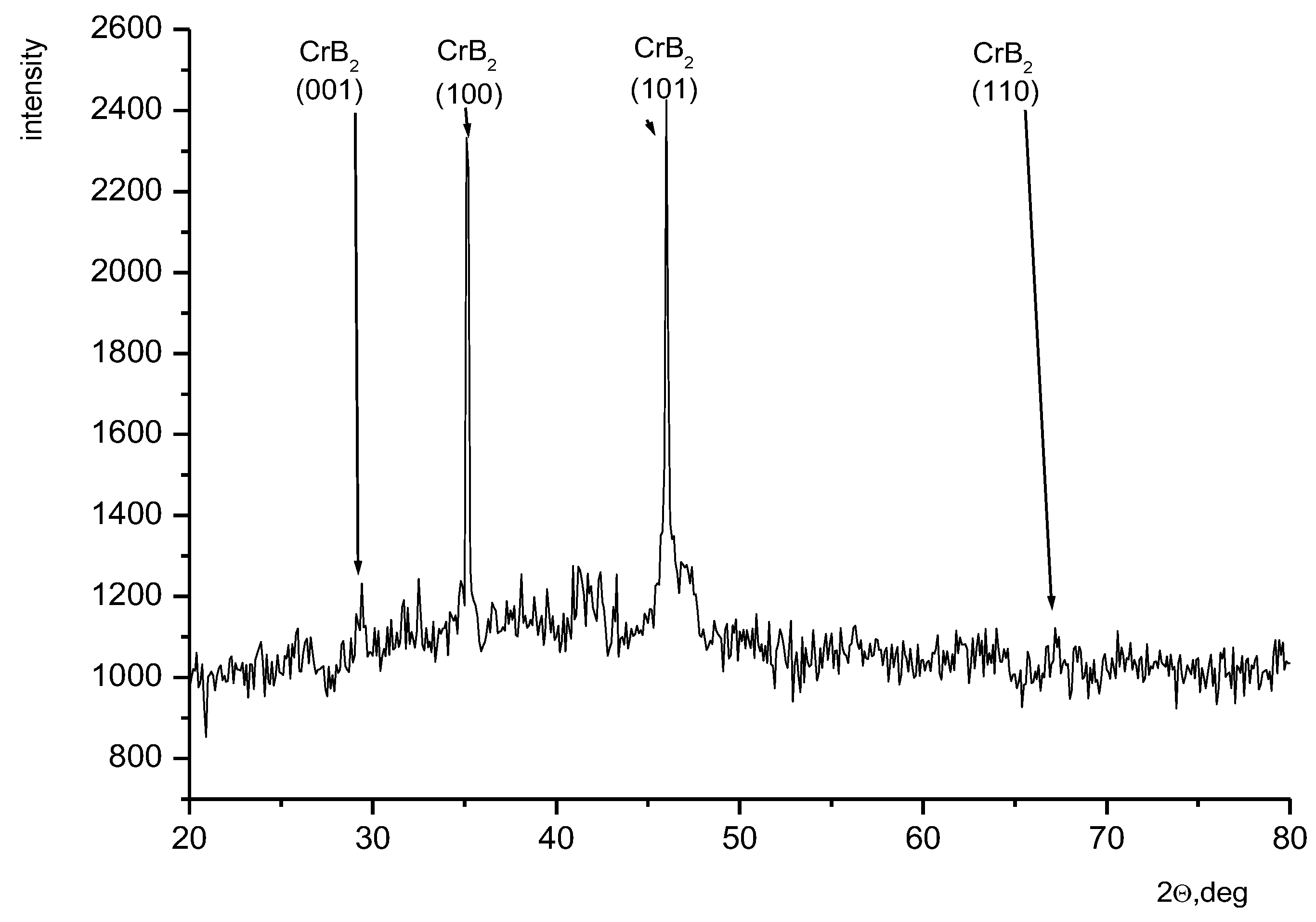
At this stage of research on PDC bits, it is important to note the novel diamond-reinforced composite material for cutting insert. The addition of chromium diboride to the WC-Co matrix was found profitable, especially in a proportion of 4 wt%, which ensured an improvement of bending strength and fracture toughness by nearly 30% and 40%, respectively. However, the most spectacular benefit of the CrB2 additive was the enhancement of the diamond retention force. The holding capacity became high enough to keep the diamond grits in place during fracture testing, with cracks going through the diamond. This result can most likely be attributed to the mechanical clamping forces that appeared as a result of compressive residual stresses generated by the fabrication technology. The novel electroconsolidation process appears to be a promising, greener technology for the fabrication of diamond-reinforced cutters.
It was demonstrated that the further improvement of PDC bits efficiency can be reached by adding additional superhard inserts in both bottomhole and reaming parts. At this stage, it is important to work out the proper design of the cutting edges rows with proper distances to ensure simultaneous pre-cutting and removal processes.
Analytically, the relationship between feeding speed and geometrical parameters has been provided. It includes the number of wings and calibrating inserts that are directly involved in the reaming-while-drilling process, as well as the rotational speed of the cutter.
Under the conditions of rock fracture by reaming inserts, the approximate value of the required power has been calculated. This power is proportional to the rock formation’s compressive strength, the number and cross-section area of the reaming inserts, the rotational radius of the cutter, the thickness of the removed rock formation layer during reaming, and the rotation frequency of the cutter.
At this stage, each of the modifications seems beneficial for the efficiency and wear resistance of PDC drill bits. In further research, laboratory and field tests will be performed to investigate the effectiveness of the introduced details in work conditions.


 ,
, 


