
Advanced Machining of Joint Implant UHMWPE Inserts

Faculty of Mechanical Engineering, Brno University of Technology, FME IMT, 2 Technicka, 616 69 Brno, Czech Republic
*
Author to whom correspondence should be addressed.
Machines 2022, 10(11), 1008; https://doi.org/10.3390/machines10111008
Submission received: 16 September 2022
/
Revised: 25 October 2022
/
Accepted: 28 October 2022
/
Published: 1 November 2022
(This article belongs to the Special Issue Cutting Tools: Materials, Development and Performance)
Abstract
:The modern orthopaedic implants for applications in hips, knees, shoulders, and spines are composed of hard metal alloys or ceramics and a tribological sub-component that is made of soft materials, with good frictional properties—e.g., UHMWPE (Ultra High Molecule Weight Polyethylene). The UHMWPE implants need to be machined into their final shape after the polymerization and consolidation into a blank profile or near net shaped implant. Thus, machining is a crucial technology that can generate an accurate and precise shape of the implant that should comply with the joints’ function. However, the machining technology can affect the topography and integrity of the surface, transmitted stresses, and resistance to wear. Technology, cutting tools, and cutting conditions can have an impact on the physical and mechanical properties of the entire implant and its longevity. This paper shows an effective and competitive technology for acquiring high-quality insert shape, dimensions, and surface, needed especially for customized implants.
1. Introduction
Customized patient-matched technology joint replacement presents a vision for better medical care that reflects today’s knowledge of materials and computer aided technologies [1]. The technology can minimize the loss of human bone compared to the standard surgery, and the use of uniformed production series prolongs the life of implants and improves the implants’ sustainability. The design of the joint is based on a three-dimensional image of a joint made by magnetic resonance imaging, which allows the surgeons to identify the extent of a repair needed for the engineers to produce a true model of the joint, all new parts, and correct sizes. This has been proven successful in the production of the metal knee components made of Ti-6Al-4V ELI with the electron beam melting machine Arcam Q10+. The excellent material structure was based on the use of globular Ti-6Al-4V ELI parts of size 50.65 ± 22.46 μm (mean ± standard deviation) in diameter, which were melted in a vacuum chamber [2] in an optimized way of sintering. This material is difficult to machine [3], but exhibits unique structures and properties needed for femoral and tibial joint prosthesis [4] in a wide range of morphologies. The very dense, solid structures can be used for tribological, highly loaded applications and the spongious structures for a very good anchoring to the bone and bone ingrowth [5,6]. The material quality, surface integrity, mechanical properties, machinability of the alloy by grinding, polishing and tumbling, and, finally, a high resistance of the implant to fatigue and wear are crucial [6]. Such advantages open novel technologies to joint replacements [7]. However, the problem arose with the production of the “soft” part that makes the tribological contra part. The part for individual knee design should be machined from a solid block of material. The basic machining technologies are turning and milling (each can be used as roughing or finishing). There are many ways to machine these surfaces. Nevertheless, problems such as low rigidity of the product, poor thermal properties of the material, high melt viscosities, and sticking of the material to the cutting edge (production of built-up edges) should be faced. The UHMWPE material may be damaged by excessive heat, feed rate, cutting force, and tool micro-geometry. The shapes and dimensions of the customized implants vary broadly in humans, which complicates the machining technology. No standard programs like those used for unified implant shapes and dimensions can be used repeatedly, so each joint must be designed and produced individually. However, this results in a longer implant life and better comfort for patients. Many producers do not publish the details about precise machining of the UHMWPE parts, but dry or cryogenic machining, vacuum fastening of the workpieces, very sharp cutting tools, and low cutting conditions are generally known and recommended. The rotational parts are turned, but the shaped parts (as the femoral joint inserts) can be milled with ball milling cutters only due to complex geometries of the functional surfaces. This technology prevails for the standardized joint parts produced in various sizes and series. The main advantage of the technology is to satisfy current needs in situ at the joint surgery in the hospital. However, the machining should be studied more, because the quality of the functional part surfaces affects the total success of the arthroplasty and longevity of the implants.
2. Materials and Methods
2.1. Material and Design of Joint Inserts
There are more than one hundred design solutions for knee implants all over the world, but there is a strong development in customized products, individual to each human or animal. Basically, the solutions are principally similar, and most of them contain an insert to guarantee a low friction interface between the femoral and tibia parts made from metal alloys or ceramics [8,9]. The use of UHMWPE for the insert seems to be prevailing [10,11,12] and longstanding [13] in surgical practice. The material was polymerized in the 1950s and the first UHMWPE fibres were commercialized in the late 1970s. UHMWPE is a type of polyolefin that is composed of very long chains of polyethylene with a very high percentage of parallel orientation and a high level of crystallinity. The extremely long polymer chains enable load transfer by strengthening intermolecular interactions. The materials suffer from gamma radiation, which affects their molecular stability and mechanical properties like other materials for medical applications [14], but so far their tribological properties and resistance to fatigue are unique [15] and there are many technologies for processing it according to the advanced standards [16,17,18,19]. This specification [16] covers UHMWPE powder and fabricated forms for use in surgical implants. UHMWPE powder shall be of virgin polymer manufactured from a homopolymer of ethylene. Tests for viscosity number, elongation stress, ash content, extraneous matter, and trace elements shall be performed for UHMWPE powders, while tests for density, ash content, tensile strength, yield strength, elongation, and impact strength shall be performed for fabricated forms. The document [17] specifies the requirements and corresponding test methods for moulding materials in powder form made from UHMWPE for use in the manufacture of surgical implants. The standard [18] specifies the requirements and corresponding test methods for moulded forms, e.g., sheets and rods, made from UHMWPE for use in the manufacture of surgical implants. This document is not applicable to direct-moulded, irradiated, or finished products, or products manufactured from polyethylene blended with additives or by blending different forms of polyethylene. The document [19] specifies a test method for investigating the oxidative stability of UHMWPE materials as a function of the processing and sterilization method.
There are plenty of other applications in a wide range of contacting surfaces—forming, manipulation of materials, guiding pads, supporting units, etc. There are some typical problems with machining them to the specified shapes, dimensions [20], and high-quality surfaces [21,22].
It has been frequently confirmed that this insert part suffers either from the high specific loading and/or specific material properties, so its intensive wear in knee implant applications is very common–Figure 1 and Figure 2. The origins come generally from the material composition [10], technological processing, application, and use [23,24,25,26,27,28,29]. Observations of wear damage in [23] were performed on retrieved worn porous coated anatomic tibial components. The nonconforming articulating surfaces on thin polyethylene components would be at higher risk of damage than more conforming surfaces on thicker components. Moreover, the high cyclic loads are most responsible for the degradation in properties of the material near the articulating surface. According to [24], the wear of materials causes different consequences depending on the type of the system in which it occurs. In biological systems, particles produced by wear elicit an environmental response, terminating the life of the bearing system as in hip and knee joint prostheses. It is shown that polyethylene wear produces sub-micrometer particles, which are known to contribute to osteolysis and implant loosening. The mechanisms responsible for production of polyethylene wear particles are mainly ploughing and abrasion by hard asperities and/or wear particles, as well as delamination wear. The potential for osteolysis induced by wear debris is highlighted by the work [25] also. These results suggest that early knees may have similar wear mechanisms and indicate that similar volumes of biologically active micrometer and sub-micrometer UHMWPE particles were produced, which may have important implications in the longer-term outcome of total knee arthroplasties. Another wear mechanism—delamination, in which a thin surface sheet of polyethylene separates from the deeper layers—was confirmed in [26] and some earlier works also. It has been confirmed that the delamination is not only a problem of carbon-reinforced UHMWPE, but the mechanism of damage can be found in normal UHMWPE materials. The same mechanisms and many others, such as abrasion, erosion, adhesion, etc. are also described thoroughly in [27]. The book [28] suggests a new approach to exploring the effect of applied load and surface defects on the fatigue wear behaviour of polymers. It discusses effects of surface cracks under different static and cyclic loading parameters on wear, and presents an intelligent algorithm to map the relationship between wear rate and relevant factors.
The pin-on-disc wear tests (pins of AISI F138 stainless steel or ASTM F136 titanium alloy against a UHMWPE disc, with bovine serum) were studied in [29]. The lower values of friction coefficient were measured when a thin film of polymer was transferred to the metallic surfaces, but the viscoelastic behaviour of UHMWPE was responsible for the increase in friction coefficient after a testing period.
Apart from many other tests, the parameters such as the localized Hertzian contact stresses that develop as two curved joint surfaces come in contact (and deform slightly) under the imposed loads and sliding velocity present the crucial problem. The advanced design of a customized joint implant should respect the individual human or animal anatomy and all body predispositions, and make a broad flat contact with regularly transmitted loading in dry friction conditions.
For these goals, the design starts with 3D computer tomography (CT) or magnetic resonance (MR), and computer digital reconstruction or renovation of the defected joint surfaces follows. After the production of the femoral and tibia metallic parts via, e.g., electron beam technology (EBM), a piece from the non-metallic material should be installed at the interface between the metallic implants.
This piece of material should guarantee perfect contact of the surfaces to reach a perfect sliding fit that produces minimal contact pressures and a low coefficient of friction for a long time without any lubrication. The precise profiles can be obtained, e.g., by scanning the finished metallic components and analyses of the implant cross-sections in perpendicular planes—see Figure 3.
UHMWPE is a semicrystalline polymer consisting of an amorphous matrix reinforced by a stiffer, crystalline lamellae domain (half of its structure) [8,9,10]. UHMWPE composites can be engineered in a wide range at a micro/nanometer-length scale by blending polymer powder resin with micro- or nanoparticles and fibres before consolidation. UHMWPE fibres can be woven, knitted, or manufactured into sheets forming complex structures and anisotropic properties. UHMWPE can play the role of matrix and fibre in a broad range of composite materials, depending upon the application. Polymers, which include all plastics, consist of chains of building blocks called monomers. These chains grow by adding new molecules onto their ends—Figure 4.
Once formed, polymers can be shaped into 3D objects using injection moulding and machined in standard ways by turning, milling, drilling, etc. However, polymers are difficult to cut mainly due to their viscoelastic properties, low thermal conductivity, high elasticity, and other material characteristics—Table 1. All these properties affect the chip formation and workpiece deformation, and result in deterioration of surface finish via the formation of built-up edges, chip sticking, and poor surface production. Aldwell et al. [22] recognize six types of chips formed in polymer machining, including the decisive role of shearing, cracking, and tool micro-geometry. It has been found there that workpiece pre-cooling to cryogenic temperatures (100–150 K) increases workpiece stiffness and improves surface quality in the machining of UHMWPE. To meet functional requirements and to be competitive in an economic context, it is necessary to reduce the costs of implant production. Machining strategy should respect the surface to be machined, so ball end milling cutters were the first choice. Machining time depends on the part geometry, its precision, and cutting conditions for the calculated tool paths. The optimization problem can be solved via optimization with the objectives of reducing cutting time, cutting costs, surface quality, or maximal temperature reached when machining. The manufactured surface quality stems from the cutting conditions. The tool paths are computed according to the surface curves, tool radius, feed per teeth, and radial and axial depths of cuts.
The UHMWPE material was purchased from the British company Orthoplastics. It was extruded from fine granules by GUR® 2024, manufactured by the company Celanese. The modulus of elasticity of the material was approximately 830 MPa and its density was 930 kg/m3. The semi-finished product had the shape of a prism with dimensions of 80 × 100–500 mm. Six block samples of 20 mm in thickness were cut off using a BOMAR Brno band saw, and the band saw PILANA 1640 × 13 × 0.65 /10z C125 W STANDARD at a cutting speed of 20 m/min and a feed speed of 50 mm/min without cooling.
2.2. Machining Tests
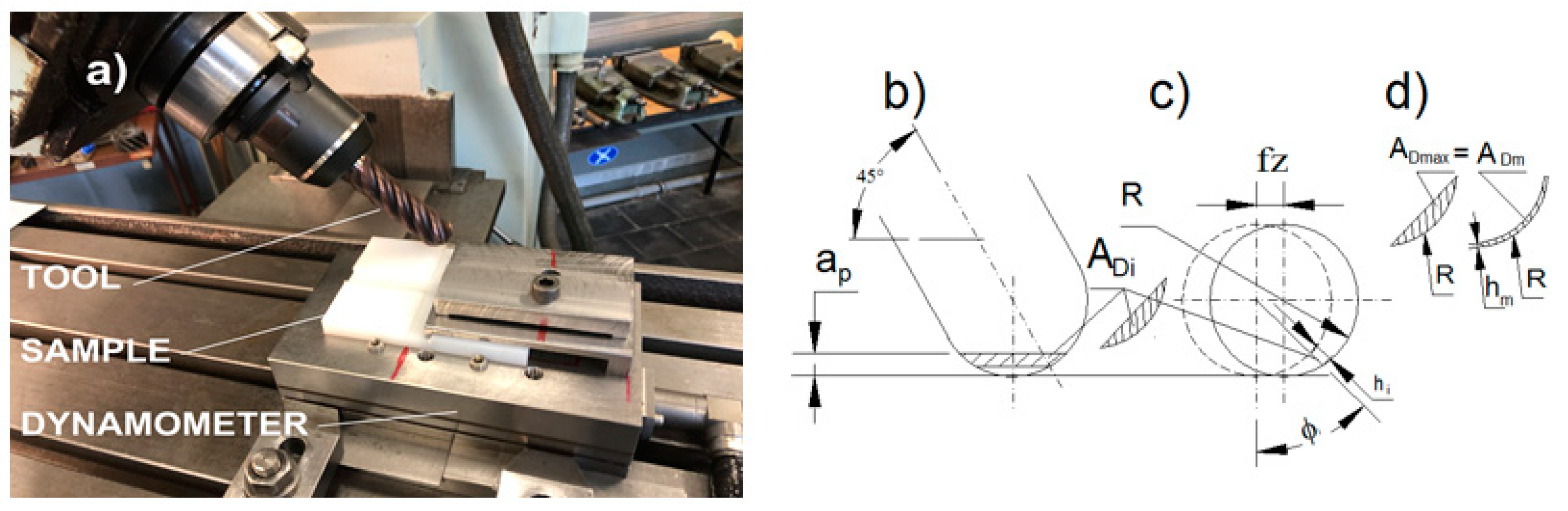
The samples were subsequently machined with face milling cutter Octomil and six indexable cutting inserts OFEX05T305FN-M05 PCD20 D125 mm from SECO Tools. The cutting speed was 300 m/min and feed rate 315 mm/min at an axial depth of cut 1 mm, without any cooling, respecting the cutting conditions mentioned in [22,23] and our preliminary tests. The rectangular plates were divided into four areas by grooves 10 mm× 5 mm along the samples, so 24 combinations of cutting speeds and feed rates could be tested by milling in the prepared areas. The spindle was inclined at 45° in all machining tests. Each area was tested twice, so real cutting speeds 70.3, 113.0, 175.8, and 282.6 m/min, radial stepover 0.35 mm, and feed rates 315, 450, and 630 mm/min were set, giving the feed 0.012–0.094 mm/tooth at the milling machine FNK 25, TOS Kurim—Figure 5a. Due to the use of a rounded cutting edge, the mean chip thickness corresponding to the angle ϕmax was recalculated from the maximal chip cross section and radius of the milling cutter R according to the Equation (1) and Figure 5b–d:
when the non-deformed chip cross sections are equalled by the relation (2)
In addition, a special arrangement of clamping (flat contact or a vacuum fastening) should be arranged, otherwise the UHMWPE flat samples tend to buckle.
The specific cutting force was calculated as a ratio of the mean cutting force and the mean chip cross section—see Equation (3):
The down dry milling was performed with a special ball end monolithic cutter SECO JS730200D3B.3Z6-HXT, ISO K10, covered with PVD AlTi(N) coating (thickness 2 μm), just developed for the machining of alumina alloys with extra sharp cutting edges for parts used in aeronautical engineering—Figure 6 and Figure 7. Alicona IF G-5 (Bruker Alicona, Graz, Austria) was used for the analysis of the cutting tool geometry and surface topography of machined samples, as well as the scanning electron microscope MIRA-3 (TESCAN Brno, Czech Republic). The piezo-electric dynamometer Kistler 9575B, the Kistler charge amplifiers Type 2825A and the DynoWare software for universal data acquisition (Kistler, Winterthur, Switzerland) were used working at the sampling frequency of 1000 Hz, the low-pass filters at 100–450 Hz, and the long time constant per each force component induced in cutting or the tribological testing. Dry machining is always the stringent rule for implant production to avoid surface contamination with an emulsion, soaking of the liquid into the plastics, etc. Each combination of cutting conditions was tested a minimum of six times to obtain statistically significant results (p < 0.05) for measurement of forces, surface quality and tribological testing. The data underwent Gaussian distribution, presented by averages and standard deviations.
New Cutting Tool
The next research was based on the references [20,22], our experience, and excellent results of single point diamond turning [30] used for the machining of polymers for optics. Apart from its unique hardness, diamond has several times (2–10×) higher thermal conductivity than other cutting materials (cemented carbides, ceramics, tool steels), so the deformation heat from cutting can be transmitted effectively through the cutting edge, suppressing a sticky effect and burr formation on the chip–tool interface. Unfortunately, the turning operations present a continuous polymer chip flow at high cutting speeds and it is not applicable for asymmetrical or more complicated shapes used in implant designs. Thus, decreasing the cutting speed was supported in our tests, but affected the time per machining, so we decided to modify the cutting edge and reflect the approximate Equation (4) for the average roughness [31]:
The general overview of the new cutting blade (a sort of inner scarfing) can be seen in Figure 8. The diameter of the tool was 30 mm and the tip radius was 0.4–0.6 μm. The prototype was made of the hardened steel DINX155CrVMo121 (62 ± 1 HRC). The cutting speed was 50 m/min, axial depth of cut 0.005 mm, and radial width of cut (the stepover) 0.010 mm.
2.3. Tribological Tests
Several research works have been dealing with the pin-on-disc techniques and effect of sliding velocity on the friction and wear of UHMWPE for use in total artificial joints [32] and tribological behaviour of ultra-high molecular weight polyethylene (UHMWPE) under dry reciprocating sliding [33].
The tribological tests in this work used a real customized implant from Ti6Al4V ELI (ground and tumbled to Ra = 0.03 μm) which was used for the analysis of friction—Figure 9. The implant fastened to the holder was pressed by forces of 20, 25, 100, and 300 N, and then was driven along the UHMWPE surface at speeds of 200, 800, 1400, and 2000 mm/min. Each combination of the thrust loading and feed speed was measured six times, and the average coefficient of friction was calculated at first approximation as the ratio of tangential and normal force (5):
3. Results
3.1. Results of Machining Tests
The force decomposition, force ratios, and time series were very similar in all cutting conditions—see Figure 10a. For the evaluations, the stabilized part of the time series was selected to define the average statistical parameters. The dominant component was the passive perpendicular force Fcn, which was nearly twice as high compared to the cutting force Fc. On the contrary, the specific milling force exhibited a very typical course, known for most known materials and technologies—see Figure 10b.
Surface topography in the ball end milling process was tested first with transverse and longitudinal steps—Figure 11a, but then continued in only longitudinal steps—Figure 11b. The cutting speed and time of milling exhibited a significant effect on the morphology of chips when milling UHMWPE, and frequently some traces of chip melting and high adhesion can be seen—Figure 12. The typical phenomena at chip production were very similar.
Surface topography confirmed the significant effect of feed speed and cutting speed on surface quality: for the best quality, only the slowest cutting and lowest feeds give the best results—Figure 13. However, the integrity of the machined surfaces wasn´t optimal. Some semi-detached particles (Figure 14 and Figure 15) or protuberant fibres (Figure 16) affected the solid surface and possibly could contribute to the production of debris on the surfaces in sliding contact. The production of the asperities stems from the kinematics of the milling technology (Figure 17) in general, but is enhanced by the plastic flow of the polymer fibres also.
To smooth the surface, drag tumbling technology was used. The machine was OTEC DF 3-4 (Straubenhardt, Germany)—Figure 18—and it worked in two regimes for roughing and finishing with different abrasives—Figure 19 and Figure 20: the small rotor, d = 190 mm, n = 120 [1/min], SiC abrasives, 10 min polishing, and the big rotor, D = 330 mm, n = 30 [1/min], diamond abrasives (1–2 μm) in nut crushed shells, 15 min polishing.
The reverse rotations were always after 12 s of tumbling in both regimes, and the vertical speed was 1200 mm/min at a total height of 150 mm.
However, a deeper analysis of the speeds, accelerations, and trajectories should be done beforehand: the maximal polishing effect was found at the maxima of accelerations, so the rotations must be set in such a way that the whole surface is ground regularly and uniformly—Figure 18b,c. Nevertheless, the use of this technology is rather limited, because some abrasive particles have been found jammed in the tumbled surface—Figure 21. From our point of view, this fact precludes the use of the technology for finishing of the UHMWPE materials as implant applications, because even one diamond particle would be able to scratch the contacting surfaces.
The last way to smooth the machined surface was thermal ironing of the irregularities, because the temperature for UHMWPE softening is very low—around 135 °C (see Table 1). A polished steel ball of 30 mm in diameter (Figure 22), a steel bearing of 50 mm in diameter (preheated in an oven), a commercial flat iron (with inner electrical heating), and a special apparatus was used for this experiment. In actuality, the hand polishing operation worked very well, with a reduction of all amplitude characteristics of about 50%—Figure 23, Table 2. The results cannot be overestimated, because there is no information about chemical bonds in the UHMWPE surface and their deteriorations.
The new cutting tool performed at low cutting speeds with excellent surface roughness, free of the burrs—Figure 24, exhibiting Ra < 0.1 μm. There is one important condition for reaching such a good surface—to make the roughing and finishing condition at one clamping, without any releasing of the machined part from the clamping and CNC machine. The tool life expressed in the total machined area was about 12,000–14,000 mm2 per tool.
3.2. Results of Tribological Tests
The results—see Table 3 and Figure 25—confirmed excellent tribological behaviour of the pair of surfaces and extremely low friction was found: 0.07–0.11. A slight effect of normal forces on the coefficient of friction was proved, but more significant feed speed was confirmed. Then, the mean value and standard deviations (SD) were calculated from all force data at a constant feed speed. A slight rise of the coefficient of friction with the increasing feed speed was found also. Possibly, the higher speeds generated more heat and the surface started to be plastically deformed, which resulted in a sticking effect of the contact regions.
4. Discussion
First, the material exhibited a very common course of specific cutting force at milling, like many other technical materials. The thinner the layer separated by chip removal, the higher specific resistance of the deformed material can be expected. On the contrary, testing of the cutting speed magnitudes confirmed that the best surface quality was achieved, surprisingly, at the lowest cutting speed and the lowest feed speed. The use of high cutting speeds and feed with the cemented carbide tool resulted in the accumulation of plastic energy at the place of chip removal, with a limited heat flux. The material heated up and started to melt, with all deteriorating effects on chip formation and quality of the machined surface, even at mild cutting conditions. The crucial problem is the principle of milling, which interrupts cutting action and initiates the production of the “fish scales” at all cutting conditions used in this work. The distribution of the local irregularities depends on cutting conditions, and can be reduced partially with low feed per tooth, tool oversteps, and low cutting speed. However, it affects the productivity of the machining operation. The same problems of surface integrity, material pile-ups, and other technological phenomena of surface quality have been found in [22] and [30] also. Shintoku and Narita, in their study of inclined plane milling technology [22], concluded that the best-quality machining results have been found at a feed rate in the range of 120–240 mm/min and a cutting speed of 50 m/min. The range of cutting conditions is comparable to the milling parameters used in our research (315 mm/min, 70 m/min). In that work, it was also confirmed that the feed rate has a higher impact on the resulting quality than the cutting speed, but this is logical due to Equation (2). The high ratio of passive forces found in [22] constitutes a new finding, because the fact is known typically for grinding technology (the use of a negative rake geometry of grinding grains). However, in the milling of plastics, very sharp cutting edges are used normally, so the higher values of Fcn than Fc can be explained by the visco-elastic behaviour of the material, the intensive plastic flow of the machined material, and an extreme ploughing effect of the cutting tool when the chip is formed. In other words, the energy needed for the tertiary plastic deformation [31] was higher compared to the energy consumed for the primary plastic deformation. The structure of the UHMWPE, the low modulus of elasticity, the low thermal conductivity, and the low temperature of plastic flow support the occurrence of this phenomenon.
The thermo-mechanical post-processing confirmed that it may be a way of smoothing of the surfaces, but the re-melting and intensive plastic deformation may have an effect on the polyethylene chains with unpredicted aftereffects. The fact that mechanical milling can cause a phase transformation of UHMWPE can be found in [34] also.
Pre-cooling of the material, or cryogenic machining, is a very good technology for implant production [35,36], verified especially on the Ti-6Al-4V alloy, but very advanced equipment and technology is needed. The turning technology using diamond tools and high cutting speeds [22] is difficult to apply to the general shapes and advanced tool trajectories needed for real artificial joints. Our innovation, based on the use of extremely sharp tools and the technology of scarfing, seems to be more realistic for serial use. A special design of a rounded tool similar to inner scarfing of welded tubes was designed (patent pending) and has been tested on.
The tribological test confirmed the result of the extra-low friction coefficient against the prototype knee implant (made of Ti6Al4V ELI by the technology EBM) and the friction dependent on the motion speed, not the normal force, but not very dramatically. It confirmed a very small effect of speed on friction and wear, as has been found in the pin-on-disc test [32,33]. The higher speeds can generate some frictional heat, but they are far enough in their magnitudes compared to a range used in normal walking.
5. Conclusions
For the high longevity of the implant, it is necessary to achieve the best possible surface integrity in order to avoid any possible stress risers in the material. This research work confirms that UHMWPE is a very good material for tribological applications in implant insertions, but it is difficult to machine. To get an acceptable surface quality, a very low cutting speed and a combination of milling (for roughing with cemented carbide ball milling tool) and scarfing of the asperities (for finishing with a hardened steel cutting tool) of the functional surfaces are recommended, with no cooling. This has a serious impact in practice because no cryogenic apparatus is needed. However, a rigid machine with a very sharp cutting edge and preservation of technological sequence (roughing followed with finishing, without any release of the insert from a clamping device and no interruption of the cutting action at the surface) should be kept. If the material is consolidated well, the finished surfaces after machining are smooth, glossy and without any defect of integrity. All the results are important to finalize the whole assembly of customized implants and extend the lifespan of the insert, thus maximizing the re-operation period for patients or eliminating the necessity to replace the insert altogether.
Author Contributions
Conceptualization, M.P. and K.U.; methodology, M.P.; validation, M.P. and K.U.; formal analysis, K.U.; investigation, M.P.; resources, K.U.; data curation, M.P.; writing—original draft preparation, M.P.; project administration, M.P.; funding acquisition, M.P. All authors have read and agreed to the published version of the manuscript.
Funding
This research was funded by the PID grant FV40313, Application of the New Surface Treatment Technologies in Metal Packaging Industry, and by the Brno University of Technology, Faculty of Mechanical Engineering, Specific research “Modern technologies for processing advanced materials used for interdisciplinary applications”, FSI-S-22-7957.
Data Availability Statement
Not applicable.
Acknowledgments
A special thanks go to the company Astra Motors, s.r.o., Brno, Czech Republic, represented by Jan Keprda, for his kind help in the technology of drag tumbling, and to Phillip Jones for his English corrections.
Conflicts of Interest
The authors declare no conflict of interest.
References
- World Health Statistics 2021: Monitoring Health for the SDGs, Sustainable Development Goals; World Health Organization: Geneva, Switzerland, 2021; ISBN 978-92-4-002705-3.
- Píška, M.; Bučková, K. On the analysis of Ti6Al4V-ELI powder material, electron beam technology and machining on quality of machined implant surfaces. In Proceedings of the European Advanced Material Congress, Stockholm, Sweden, 20–23 August 2018; VBRI Press: Stockholm, Sweden, 2018; pp. 257–258, ISBN 978-91-88252-12-8. [Google Scholar]
- Píška, M.; Bučková, K. On the machining of Ti-6Al-4V ELI alloy made with EBM technology for implants. In Proceedings of the UTIS 9th International Congress on Machining Congress Proceedings, Antalya, Türkiye, 8–11 November 2018; UTIS Royal Seginus: Antalya, Türkiye, 2018; pp. 242–247. [Google Scholar]
- Píška, M.; Bučková, K. Advanced knee implants for the third millenium. J. Mater. Sci. Eng. 2019, 8, 20–21. [Google Scholar]
- Píška, M.; Bučková, K. Analysis of machined electron beam treated Ti6Al4V-ELI implant surfaces. Adv. Mater. Lett. 2019, 10, 381–385. [Google Scholar] [CrossRef]
- Píška, M.; Bučková, K. On the SLM and EBM of Ti-6Al-4V ELI Alloy for Advanced Knee Arthroplasty; Bone Research Society and British Orthopaedic Research Society: Cardiff, Wales, 2019; p. 92. [Google Scholar]
- Píška, M.; Bučková, K. A Set for Application of Joint Implant. Czech Patent No 309024, 2021. [Google Scholar]
- Katti, K.S. Biomaterials in total joint replacement. Colloids Surf. B Biointerfaces 2004, 9, 133–142. [Google Scholar] [CrossRef] [PubMed]
- Kurtz, S.M. UHMWPE Biomaterials Handbook-Ultra-High Molecular Weight Polyethylene in Total Joint Replacement and Medical Devices, 3rd ed.; Drexel University: Philadelphia, PA, USA; Elsevier: Amsterdam, The Netherlands, 2015. [Google Scholar]
- Malito, G.L.; Arevalo, S.; Adam, K.; Stephen, S.; Anuj, B.; Lisa, P. Material properties of ultra-high molecular weight polyethylene: Comparison of tension, compression, nanomechanics and microstructure across clinical formulations. J. Mech. Behav. Biomed. Mater. 2018, 83, 9–19. [Google Scholar] [CrossRef] [PubMed] [Green Version]
- Panayotov, I.V.; Orti, V.; Cuisinier, F.; Yachouh, J. Polyetheretherketone (PEEK) for medical applications. J. Mater. Sci. Mater. Med. 2016, 27, 118. [Google Scholar] [CrossRef]
- Mckeen, L.W. Fatigue and Tribological Properties of Plastics and Elastomers, 3rd ed.; Elsevier: Amsterdam, The Netherlands, 2016. [Google Scholar]
- Zaribaf, F.P. Medical-grade ultra-high molecular weight polyethylene: Past, current and future. Mater. Sci. Technol. 2018, 34, 1940–1953. [Google Scholar] [CrossRef]
- Katarzyna, G.; Sylwester, G. The effect of gamma radiation on molecular stability and mechanical properties of biodegradable polyurethanes for medical applications. Polym. Degrad. Stab. 2003, 79, 465–474. [Google Scholar]
- Ducháček, V. Polymery: Výroba, Vlastnosti, Zpracování, Použití, 2nd ed.; VSCHT: Prague, Czech Republic, 2006; ISBN 80-708-0617-6. (In Czech) [Google Scholar]
- ASTM F648-21, 10th ed.; Standard Specification for Ultra-High-Molecular-Weight Polyethylene Powder and Fabricated Form for Surgical Implants; ASTM international: West Conshohocken, PA, USA, 2021.
- ISO 5834-2:2019; DIN ISO 5834-1 Implants for Surgery-Ultra-High-Molecular-Weight Polyethylene-Part 1: Moulded Forms. ISO: Geneva, Switzerland, 2019.
- ISO 5834-2:2019; DIN ISO 5834-2 Implants for Surgery-Ultra-High-Molecular-Weight Polyethylene-Part 2: Moulded Forms. ISO: Geneva, Switzerland, 2019.
- ISO 5834-1:2019; DIN ISO 5834-1 Implants for Surgery-Ultra-High-Molecular-Weight Polyethylene-Part 3: Powder Form. ISO: Geneva, Switzerland, 2019.
- Axinte, D.; Guo, Y.; Liao, Z.; Shih, A.J.; M’Saoubi, R.; Sugita, N. Machining of biocompatible materials—Recent advances. CIRP Ann. 2019, 68, 629–652. [Google Scholar] [CrossRef]
- Aldwell, B.; Hanley, R.; O’Donnell, G.E. Characterising the Machining of Biomedical Grade Polymers. Proc. Inst. Mech. Eng. Part B J. Eng. Manuf. 2014, 228, 1237–1251. [Google Scholar] [CrossRef] [Green Version]
- Kousuke, S.; Narita, H. Study on Ball End Milling of Inclined Surfaces for Ultra High Molecular Weight Polyethylene. Int. J. Autom. Technol. 2017, 11, 948–957. [Google Scholar]
- Wright, T.M.; Rimnac, C.M.; Stulberg, S.D.; Mintz, L.; Tsao, A.K.; Klein, R.W.; McCrae, C. Wear of Polyethylene in Total Joint Replacements Observations From Retrieved PCA Knee Implants. Clin. Orthop. Relat. Res. 1992, 214, 124–134. [Google Scholar] [CrossRef]
- Mohsen, M.; Suh, N. Wear Particles of Polyethylene in Biological Systems. Tribol. Trans. 1996, 39, 843–848. [Google Scholar]
- Howling, G.I.; Barnett, P.I.; Tipper, J.L.; Stone, M.H.; Fisher, J.; Ingham, E. Quantitative characterization of polyethylene debris isolated from periprosthetic tissue in early failure knee implants and early and late failure Charnley hip implants. J. Biomed. Mater. Res. 2001, 58, 415–420. [Google Scholar] [CrossRef] [PubMed]
- Tulp, N.J.A. Polyethylene delamination in the PCA total knee. Material analysis in two failed cases. Acta Orthop. Scand. 2009, 63, 263–266. [Google Scholar]
- Evans, D.C.; Lancaster, J.K. The Wear of Polymers; Wear; Elsevier: Amsterdam, The Netherlands, 1979; Volume 13, pp. 85–139. [Google Scholar]
- Abdelbary, A. Wear of Polymers and Composites, 1st ed.; Elsevier: Amsterdam, The Netherlands, 2014. [Google Scholar]
- Wilches, L.V.; Uribe, J.A.; Toro, A. Wear of materials used for artificial joints in total hip replacements. Wear 2008, 265, 143–149. [Google Scholar] [CrossRef]
- Mishra, V.; Singh, G.; Yadav, C.B.; Karar, V.; Prakash, C.; Singh, S. Precision machining of biopolymers: A brief review of the literature and case story on diamond turning. J. Thermoplast. Compos. Mater. 2021, 34, 557–578. [Google Scholar] [CrossRef]
- Shaw, M.C. Metal Cutting Principles, 2nd ed.; Oxford University Press: Oxford, UK, 2005; ISBN 0-19-514206-3. [Google Scholar]
- Fisher, J.; Dowson, D.; Hamdzah, H.; Lee, H.L. The effect of sliding velocity on the friction and wear of UHMWPE for use in total artificial joints. Wear 1994, 175, 219–225. [Google Scholar] [CrossRef]
- Song, J.; Liu, P.; Cremens, M.; Bonutti, P. Effects of machining on tribological behavior of ultra high molecular weight polyethylene (UHMWPE) under dry reciprocating sliding. Wear 1999, 225–229, 716–723. [Google Scholar] [CrossRef]
- Gabriel, M.C.; Mendes, L.B.; Carvalho, B.d.; Pinheiro, L.A.; Capocchi, J.D.T.; Kubaski, E.T.; Cintho, O.M. High-energy mechanical milling of ultra-high molecular weight polyethylene (UHMWPE). In Proceedings of the Seventh International Latin American Conference on Powder Technology, Atibaia, SP, Brazil, 8–10 November 2010; pp. 342–346. [Google Scholar]
- Pereira, O.; Gonzáles, H.; Calleja, A.; Rodrigues, A.; Urbikaín, G.; López de Lacalle, L.N. Manufacturing of human knee by cryogenic machining: Walking towards cleaner processes. Procedia Manuf. 2019, 41, 257–263. [Google Scholar] [CrossRef]
- Gómez-Escudero, G.; Jimeno Beitia, A.; Martínez de Pissón Caruncho, G.; López de Lacalle, L.N.; González-Barrio, H.; Pereira Neto, O.; Calleja-Ochoa, A. A reliable clean process for five-axis milling of knee prostheses. Int. J. Adv. Manuf. Technol. 2021, 115, 1605–1620. [Google Scholar] [CrossRef]
Figure 1.
The UHMWPE insert for the human knee joint: (a) new one, (b) the damaged surface after several years of use.
Figure 1.
The UHMWPE insert for the human knee joint: (a) new one, (b) the damaged surface after several years of use.

Figure 2.
A detail of the worn surface of the UHMWPE insert—A deep cavity affecting the quality of the tribological contact.
Figure 2.
A detail of the worn surface of the UHMWPE insert—A deep cavity affecting the quality of the tribological contact.

Figure 3.
Digital cross-sections of a femoral knee implant, the definition of radii in sagittal (a,b) and transverse planes (c,d) for right kinematics of the adjacent part of the joint–the UHMWPE insert.
Figure 3.
Digital cross-sections of a femoral knee implant, the definition of radii in sagittal (a,b) and transverse planes (c,d) for right kinematics of the adjacent part of the joint–the UHMWPE insert.

Figure 4.
Selected basic structural characteristics of polymers after synthesis—(a) linear polymer chain, (b) branch polymer network structures.
Figure 4.
Selected basic structural characteristics of polymers after synthesis—(a) linear polymer chain, (b) branch polymer network structures.

Figure 5.
Machining experimental set-up, (a) an overview of the test arrangement, (b) undeformed chip cross-section ADi, (c) stepover when milling for feed per tooth fz, (d) a recalculation of the variable chip thickness hi along the cutting edge to the nominal mean value of chip thickness hm.
Figure 5.
Machining experimental set-up, (a) an overview of the test arrangement, (b) undeformed chip cross-section ADi, (c) stepover when milling for feed per tooth fz, (d) a recalculation of the variable chip thickness hi along the cutting edge to the nominal mean value of chip thickness hm.

Figure 6.
Ball end milling cutter SECO JS730200D3B.3Z6-HXT. (a) an overview, (b) a frontal view, (c) cutting edge geometry in the orthogonal plane.
Figure 6.
Ball end milling cutter SECO JS730200D3B.3Z6-HXT. (a) an overview, (b) a frontal view, (c) cutting edge geometry in the orthogonal plane.

Figure 7.
The ball end milling cutter and its dimensions. DMM = 20 mm, OAL = 121 mm, APMXS = 62 mm, DC = 20 mm, Z = 6, (a) sketch, (b) the rake plane Aγ, the flank plane Aα, the orthogonal plane Po, (c) the surface roughness at the orthogonal rake plane Po.
Figure 7.
The ball end milling cutter and its dimensions. DMM = 20 mm, OAL = 121 mm, APMXS = 62 mm, DC = 20 mm, Z = 6, (a) sketch, (b) the rake plane Aγ, the flank plane Aα, the orthogonal plane Po, (c) the surface roughness at the orthogonal rake plane Po.

Figure 8.
The cylindrical cutting blade for finishing the machined surface by longitudinal scarfing. (a) cutting end, (b) detail of the cutting edge.
Figure 8.
The cylindrical cutting blade for finishing the machined surface by longitudinal scarfing. (a) cutting end, (b) detail of the cutting edge.

Figure 9.
The experimental setup for testing the friction. (a) the machine FV 25CNC/Heidenhain iTNC 530, the dynamometer Kistler 9575B, and the sample clamped into vice, (b) customised joint implant in the mechanical holder.
Figure 9.
The experimental setup for testing the friction. (a) the machine FV 25CNC/Heidenhain iTNC 530, the dynamometer Kistler 9575B, and the sample clamped into vice, (b) customised joint implant in the mechanical holder.

Figure 10.
A typical time series of cutting forces when milling UHMWPE. (a) Fc-cutting force, Fcn-perpendicular cutting force, Fp-passive force, (b) specific cutting force as a function of chip thickness.
Figure 10.
A typical time series of cutting forces when milling UHMWPE. (a) Fc-cutting force, Fcn-perpendicular cutting force, Fp-passive force, (b) specific cutting force as a function of chip thickness.

Figure 11.
Surface topography in ball end milling process: (a) milling with transverse and longitudinal steps with radial stepovers ae × ae, (b) milling solely in longitudinal steps ae.
Figure 11.
Surface topography in ball end milling process: (a) milling with transverse and longitudinal steps with radial stepovers ae × ae, (b) milling solely in longitudinal steps ae.

Figure 12.
Morphology of chips when milling UHMWPE. (a–h) the effect of cutting speed, (i) the high plastic deformation of the chip, (j) traces of chip melting and high adhesion of UHMWPE to the cutting tool.
Figure 12.
Morphology of chips when milling UHMWPE. (a–h) the effect of cutting speed, (i) the high plastic deformation of the chip, (j) traces of chip melting and high adhesion of UHMWPE to the cutting tool.

Figure 13.
Surface topography in ball end milling process as a function of feed speed and cutting speed.
Figure 13.
Surface topography in ball end milling process as a function of feed speed and cutting speed.

Figure 14.
A detailed study of the surface topography at various magnifications. (a) machined surface, (b,c)—production of “fish scales” on the surface.
Figure 14.
A detailed study of the surface topography at various magnifications. (a) machined surface, (b,c)—production of “fish scales” on the surface.

Figure 15.
A distribution of the surface asperities corresponding with the cutting conditions—feed per teeth fz and radial stepover ae.
Figure 15.
A distribution of the surface asperities corresponding with the cutting conditions—feed per teeth fz and radial stepover ae.

Figure 16.
A detail of torn polymer fibres (protuberant out of the machined surface).

Figure 17.
Burr production at the down-milled UHMWPE surface—due to kinematics of cutting and visco-plasticity of the material, not all cut material is converted to a chip and removed. Legend: vc—cutting speed, vf—feed speed, ap—depth of cut, D—diameter of the milling cutter, n—rotation of the cutter, fz—feed per tooth, AD—chip cross-section, Si—position of milling cutter centre, Fc—cutting force, Fcn—perpendicular cutting force, Fp—passive force.

Figure 18.
Drag tumbling technology. (a) the machine, (b,c) an analysis of the speeds and angular accelerations of the sample.
Figure 18.
Drag tumbling technology. (a) the machine, (b,c) an analysis of the speeds and angular accelerations of the sample.

Figure 19.
Abrasives for roughing. (a) an overview of the material, (b) the SiC particles anchored in plastic cylinders.
Figure 19.
Abrasives for roughing. (a) an overview of the material, (b) the SiC particles anchored in plastic cylinders.

Figure 20.
Abrasives for finishing. (a) an overview of the material (diamond grain captured in crushed walnut shells), (b) the diamond grain.
Figure 20.
Abrasives for finishing. (a) an overview of the material (diamond grain captured in crushed walnut shells), (b) the diamond grain.

Figure 21.
A trapped diamond grain in the UHMWPE. (a,b)—a detail of the damaged surface, (c) a cross section of the place, (d) a profilogram of the inclusion according to the cut at location (c).
Figure 21.
A trapped diamond grain in the UHMWPE. (a,b)—a detail of the damaged surface, (c) a cross section of the place, (d) a profilogram of the inclusion according to the cut at location (c).

Figure 22.
The infra-red view on the experimental ironing of the machined surface.

Figure 23.
A comparison of the surfaces. (a) before ironing (b) after linear ironing with the preheated iron cylinder.
Figure 23.
A comparison of the surfaces. (a) before ironing (b) after linear ironing with the preheated iron cylinder.

Figure 24.
Scanning electron microscopy of the results: (a) finished UHMWPE surface - free of burrs, smooth (vc = 5 m/min, ap = 0.01 mm, ae = 0.2 mm), (b) surface roughness characteristics, (c) a piece of a very fine chip.
Figure 24.
Scanning electron microscopy of the results: (a) finished UHMWPE surface - free of burrs, smooth (vc = 5 m/min, ap = 0.01 mm, ae = 0.2 mm), (b) surface roughness characteristics, (c) a piece of a very fine chip.

Figure 25.
The tribological results for the coefficient of friction. (a) the effect of normal force and translative speed, and (b) the effect of the translative speed on its value for all tested normal forces (average values ± standard deviations).
Figure 25.
The tribological results for the coefficient of friction. (a) the effect of normal force and translative speed, and (b) the effect of the translative speed on its value for all tested normal forces (average values ± standard deviations).


Table 1.
Mechanical properties of selected materials used in medical applications (adapted from [8,9,10,11,12]).
| PMMA | PEEK | PUR | PP | UHMWPE | |
|---|---|---|---|---|---|
| Molar mass [g/mol] | 1.3 × 10⁴ −2.2 × 10⁵ | 1.4 × 10⁴ −1.0 × 10⁵ | 7 × 10³ −1.2 × 10⁴ | 1 × 10⁵ −6 × 10⁵ | 3 × 10⁶ −6 × 10⁶ |
| Density [kg/m3] | 1180 | 1320 | 15–600 | 900–910 | 941–965 |
| Crystallinity [%] | 0 | 16–47 | 0–13 | 60–75 | 39–75 |
| Flow temperature Tf [°C] | 1.6 | 334 | 141–150 | 176 | 135 |
| Tensile modulus [MPa] | 1800–3100 | 3000–4000 | 6 | 1325 | 655–1077 |
Comment: PMMA—polymethylmethacrylate, PEEK—polyetheretherketone, PUR—polyurethane, PP—polypropylene, UHMWPE—ultra high molecular weight polyethylene.
Table 2.
Average surface roughness after machining and thermal ironing.
| Ra [μm] | Rz [μm] | Sa [μm] | |
|---|---|---|---|
| Surface after milling | 2.49–2.61 | 18.68–19.84 | 3.63–3.68 |
| Ironing (flat contact) | 1.29–1.36 | 9.21–9.72 | 1.37–1.42 |
| Ironing (cylindrical contact) | 1.70–1.86 | 12.29–13.45 | 3.27–3.41 |
| Ironing (ball contact) | 1.93–2.02 | 14.17–14.84 | 2.58–2.72 |
Table 3.
Coefficients of friction as function of normal force and feed speed.
| Thrust Force [N] | Feed Speed [mm/min] | |||
|---|---|---|---|---|
| 200 | 800 | 1400 | 2000 | |
| 20 | 0.074 | 0.080 | 0.082 | 0.080 |
| 25 | 0.085 | 0.089 | 0.093 | 0.094 |
| 100 | 0.080 | 0.096 | 0.103 | 0.094 |
| 300 | 0.088 | 0.098 | 0.097 | 0.099 |
| Mean ± SD | 0.082 ± 0.006 | 0.091 ± 0.008 | 0.093 ± 0.009 | 0.092 ± 0.008 |
Publisher’s Note: MDPI stays neutral with regard to jurisdictional claims in published maps and institutional affiliations. |
© 2022 by the authors. Licensee MDPI, Basel, Switzerland. This article is an open access article distributed under the terms and conditions of the Creative Commons Attribution (CC BY) license (https://creativecommons.org/licenses/by/4.0/).
Share and Cite
MDPI and ACS Style
Piska, M.; Urbancova, K. Advanced Machining of Joint Implant UHMWPE Inserts. Machines 2022, 10, 1008. https://doi.org/10.3390/machines10111008
AMA Style
Piska M, Urbancova K. Advanced Machining of Joint Implant UHMWPE Inserts. Machines. 2022; 10(11):1008. https://doi.org/10.3390/machines10111008
Chicago/Turabian StylePiska, Miroslav, and Katerina Urbancova. 2022. "Advanced Machining of Joint Implant UHMWPE Inserts" Machines 10, no. 11: 1008. https://doi.org/10.3390/machines10111008
Note that from the first issue of 2016, this journal uses article numbers instead of page numbers. See further details here.