Article

Processing Strategies for Dieless Forming of Fiber-Reinforced Plastic Composites †

Institute of Aircraft Production Technology, Hamburg University of Technology, Denickestr. 17, 21073 Hamburg, Germany
*
Author to whom correspondence should be addressed.
This article is an extended version of the conference paper Rath, J.-E.; Graupner, R.; Schüppstuhl, T. Die-Less Forming of Fiber-Reinforced Plastic Composites. In Flexible Automation and Intelligent Manufacturing: The Human-Data-Technology Nexus, Proceedings of the FAIM 2022, Detroit, Michigan, USA, 19–23 June 2022; Kim, K.-Y., Monplaisir, L., Rickli, J., Eds.; Springer International Publishing: Cham, Switzerland, 2023; pp. 3–14. https://doi.org/10.1007/978-3-031-18326-3_1.
Machines 2023, 11(3), 365; https://doi.org/10.3390/machines11030365
Submission received: 23 January 2023 / Revised: 22 February 2023 / Accepted: 4 March 2023 / Published: 8 March 2023

Abstract

:
The demand for lightweight materials, such as fiber-reinforced plastics (FRP), is constantly growing. However, current FRP production mostly relies on expensive molds representing the final part geometry, which is not economical for prototyping or highly individualized products, such as in the medical or sporting goods sector. Therefore, inspired by incremental sheet metal forming, we conduct a systematic functional analysis on new processing methods for shaping woven FRP without the use of molds. Considering different material combinations, such as dry fabric with thermoset resin, thermoset prepreg, thermoplastic commingled yarn weave and organo sheets, we propose potential technical implementations of novel dieless forming techniques, making use of simple robot-guided standard tools, such as hemispherical tool tips or rollers. Feasibility of selected approaches is investigated in basic practical experiments with handheld tools. Results show that the main challenge of dieless local forming, the conservation of already formed shapes while allowing drapability of remaining areas, is best fulfilled by local impregnation, consolidation and solidification of commingled yarn fabric, as well as concurrent forming of prepreg and metal wire mesh support material. Further research is proposed to improve part quality.

1. Introduction

Their high structural strength-to-weight ratio makes fiber-reinforced plastics (FRP) increasingly popular in the aircraft and automotive industries, medical and sports equipment manufacturing and other lightweight applications. In FRP production, fibers with high strength, such as carbon, glass or aramid fibers, are embedded in a moldable polymer matrix, which is responsible for introducing external forces into the fibers, protecting them from environmental influences and securing the component geometry, which is most often shell-shaped [1,2]. Basic manufacturing steps are the shaping of the desired geometry, impregnation of the fibers with matrix, consolidation and curing/solidification, followed by eventual post-processing [1]. Thermoset matrix materials, such as reactive epoxy resins, are converted into a solid through chemical crosslinking, forming a three-dimensional network [2]. In contrast, thermoplastic polymers do not exhibit chemical crosslinking and can therefore be softened and reshaped with the aid of heat [3]. Either, the final component geometry and the composite material are produced at the same time using dry fibers and an initially separate matrix, or semi-finished products, fibers already impregnated with a matrix (prepregs), are used [3]. In the case of thermoplastic polymers, two-dimensional fully impregnated and consolidated solid organo sheets are a common semi-finished product, which need to be heated before forming [4].
A common manufacturing processes for composites with thermoset polymer is resin transfer molding (RTM), where dry reinforcements are cut, preformed and placed in a heated mold. After closing the mold, low viscosity resin is injected and the part is cured [1]. Thermoplastic prepregs, including heated organo sheets, are often thermoformed into shape using two heated molds [1]. Various similar forming processes exist for thermoset and thermoplastic prepregs, such as vacuum bagging, diaphragm forming or autoclave processes, using just one mold [1]. Automated Tape Laying (ATL) or Automated Fiber Placement (AFP) can be used to automatically place the prepregs on the usually large and simply curved molds [5]. A manual manufacturing process for smaller series is hand-layup, where dry textiles are placed on an open mold surface, before thermoset resin is applied and compacted with a roller [1,6].
All of the conventional manufacturing processes presented require at least one mold, whose design and fabrication are time-consuming and costly. Consequently, they are not economically applicable for small batch sizes such as in prototyping or individualized product production [7], which is in conflict with the general trends of higher variant diversity and increasing cost pressure. Therefore, realization of a flexible, automated and dieless forming process for FRP production would be beneficial [7,8].
To approach this, we will first highlight the most relevant existing approaches on flexible and dieless forming of shell-shaped FRP components. Subsequently, we analyze process requirements, define processing functions and develop possible solutions for dieless forming of different FRP material combinations. The proposed processes are rated according to their theoretic feasibility and the most promising ones practically investigated in basic experiments. Thus, the general applicability of the process ideas can be evaluated and discussed and the paper closed with an outlook.

2. Related Work

To reduce tooling efforts, rapid tooling, flexible molds and completely dieless processes can be distinguished. The former includes indirect mold production, meaning the generation of a positive form or pre-mold, for example, through additive manufacturing and subsequently replicating the mold through metal or resin casting, hand-layup or similar [9,10]. Examples of direct rapid tooling processes are rapid machining or additive manufacturing of metal or polymer molds [11,12], as well as the generation of metal molds through incremental sheet-forming (ISF) [13,
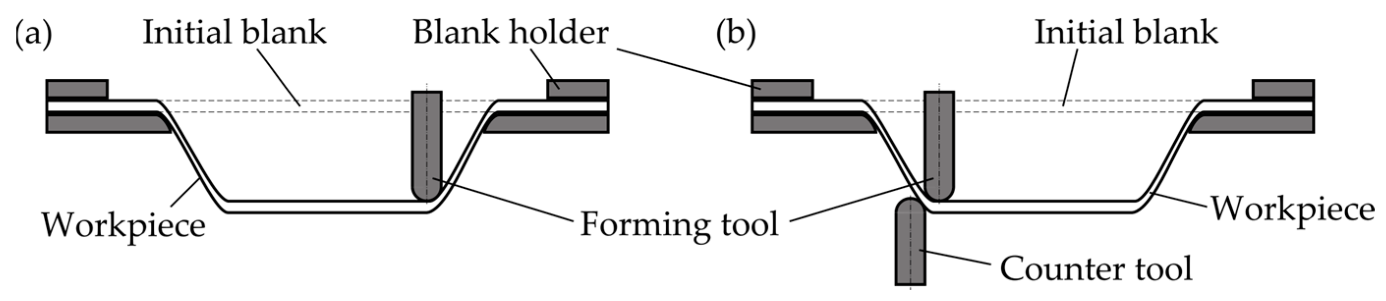
14]. ISF is an established process for dieless forming of metal sheets, in which one or two simple forming tools, usually hemispherical tool tips, are moved by CNC machines or robots along the surface of a fixedly clamped sheet, introducing strains and progressively forming the material. By changing the tool path, the process can be quickly adapted to new part shapes, enabling cost-effective production of small series. Different process variants, depicted in Figure 1, include single-point incremental forming (SPIF), with just one standard tool, and double-sided incremental forming (DSIF) using two tools, one on each side of the sheet [15,16].
An example of a flexible mold is multi-point forming, where an array of individually length-adjustable pins, covered by a smoothening diaphragm, constitutes a tool with variable geometry [17,18]. Going more into the direction of dieless forming, Miller et al. [19] used an array of individually adjustable rollers, and Strong and Hauwiller [20] used a modular press to form long endless-fiber reinforced organo sheets with varying cross-sections, heating only a certain length of the sheet for local forming. Cedeno-Campos et al. [21] demonstrated local curing of thermoset prepregs, applying pressure and heat by a small punch, without forming the material.
Over the last years, multiple approaches were made to directly apply incremental sheet-forming to fiber-reinforced plastics. Fiorotto et al. [14] investigated the forming of a woven thermoset prepreg, stating that plastic deformation was not possible and resin would be removed from the laminate by the tool. Thus, they used a vacuum bag to apply the prepreg to a metal diaphragm, separated by a nylon peel ply, in order to protect the laminate surface and maintain the deformation during SPIF. Xiao et al. [22] added a die to the setup which was placed under the clamped sheet, realizing a hybrid, or two-point, incremental forming process.
Since incremental forming of thermoplastic sheets has been successfully demonstrated [15,23], more research is concerned with ISF of fiber-reinforced thermoplastics (FRTP). Using a SPIF-like setup, Ikari et al. [24] formed short-fiber reinforced organo sheets with a round tool tip by locally heating the thermoplastic with an infrared spot heater and pressing the tool into the sheet to the target z-coordinate, in each x-y-coordinate. Defects occurred and the resulting shape accuracy needed to be improved. Also, Conte et al. [25], Torres et al. [26] and Bagheri et al. [27] found that direct application of ISF to short-FRTP is challenging, as formability decreases with higher fiber volume content, and cracks occurred at relatively small forming depths. Therefore, Conte et al. [25] and Ambrogio et al. [28] superimposed an aluminum dummy sheet on the organo sheet, which prevented direct contact of tools and FRTP and aided in more successfully forming the FRP. From below, the organo sheet was heated for formability.
Al-Obaidi et al. [29] and Emami et al. [30] introduced a second metal sheet, which was placed on the lower side of an unidirectional endless-FRTP sheet, to homogenize global hot air heating of the matrix and limit its outflow in molten state. Teflon layers were introduced between the FRTP and the upper and lower support sheets to reduce adhesion. However, due to the high tensile strength and limited strain of the reinforcement fibers, the effect of stretching underlying conventional metal SPIF is not applicable for endless-FRTP [14,19]. Thus, fiber breakage occurs when fibers cannot be sufficiently drawn in to the forming area, due to clamping or high fiber volume content [29,30,31]. To prevent this, Conte et al. [32] recently proposed to press an unidirectional long-fiber reinforced thermoplastic sheet onto a clamped metal sheet by fluidic pressure, simultaneously using the fluid as a homogenous heating source as introduced by [26]. As an FE simulation showed, the metal and organo sheets could be then simultaneously formed by SPIF [32]. After similar considerations, Al-Obaidi et al. [33], as well as Hou et al. [31], sandwiched woven FRTP between two metal and Teflon layers, however, not clamping the organo sheet, but leaving it freely movable between the support. Defects, such as wrinkles, occurred, especially with higher wall angles, as the fiber movement was not determinate and the main draping mechanisms of woven textiles were not considered.

3. Process Analysis

As it can be seen from the described state of the art, dieless forming of endless-FRP is not a trivial undertaking, as local deformation of the textile is only possible through fiber movement in adjacent regions, while already generated shapes should be maintained. Metallic support sheets can aid in this; however, under deformation mechanisms, which are very different to endless-FRP. Therefore, the aim of this research is to conceptualize and evaluate new processes for the dieless forming and production of endless-FRP. Thereby, only one or two reusable standard tools for local deformation, and possibly some low-cost auxiliary material, should be used in a setup enabling automated forming, similar to ISF. This work will focus on woven fabrics, which offer a high level of tailorable reinforcing properties and comparably good drapability [6]. However, some of the concepts deduced in the following might also be applicable for other reinforcement textile fabrics.
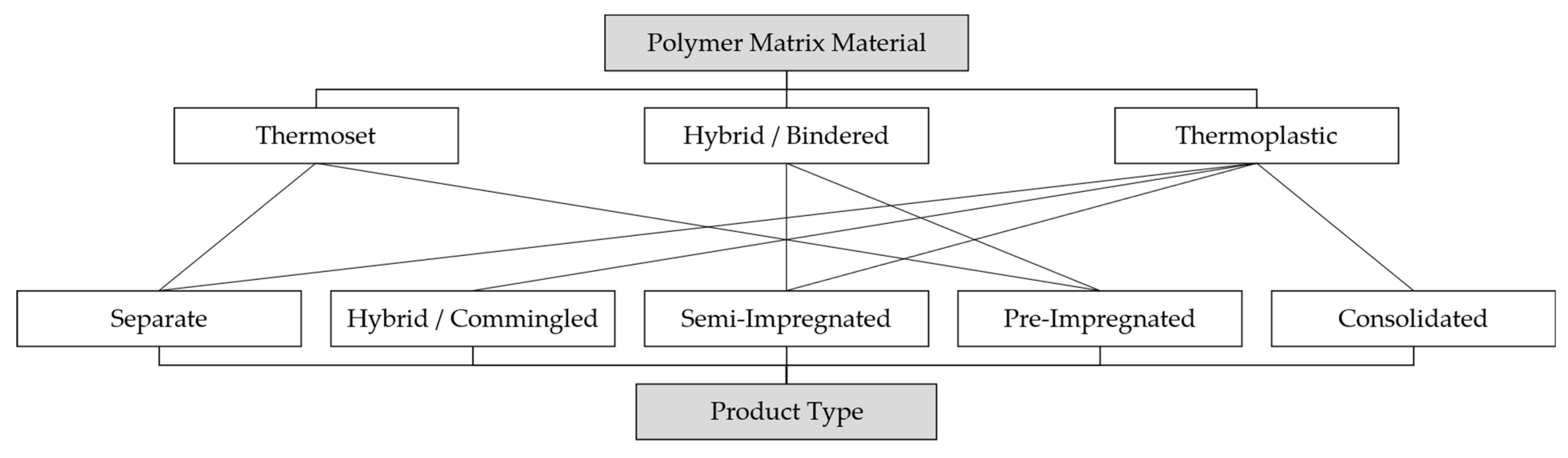
3.1. Materials

As reinforcement fiber material, research will focus on glass and carbon fibers, however, disregarding differences within the material groups at this first concept stage. Instead, we assume inextensibility and sufficient drapability of both material categories, electric conductivity of carbon fibers, and light transmissibility of glass fibers. The developed concepts may also be applicable for other fiber materials with similar properties.
Similarly, three categories of matrix materials are considered. While thermoset polymers are mostly provided as resins with comparably low viscosity, curable, for example, through initialization by heat or UV-light, thermoplastics are usually solid at room temperature, and have to be heated for processing [34]. A combination of both are hybrid matrices or bindered systems, where a thermoplastic binder is applied to the fibers, for example, in the form of polymer powder, before thermoset impregnation. In a heated state, the bindered fabric can be deformed, while, in a cooled state, the binder aids in fixating a 3D preform [34].
Different types of semi-finished products are available to combine reinforcement fibers and polymer matrices. Starting with an initially separate woven textile and matrix, full drapability of the fabric is assured. However, efforts are necessary to fully impregnate the fibers, which is especially cumbersome in the case of thermoplastic polymer matrices, due to their high viscosity [1]. This problem can be addressed by reducing the length of the flow paths necessary for full impregnation, which is targeted by hybrid weaves or woven commingled yarns [35]. Here, reinforcement and thermoplastic fibers are used as warp and weft tows, or mixed in individual yarns, respectively [36], maintaining good drapability. A very similar approach is semi-impregnation of textiles with thermoplastic matrices, for example, through powder deposition and melting [35]. However, depending on the degree of impregnation, drapability at room temperature can be very limited, requiring heating to achieve formability. This trend reaches its maximum in fully impregnated and consolidated rigid organo sheets. In contrast, fabrics pre-impregnated with thermoset resin are still well-formable, however tacky, and only processable for a limited time to prevent premature polymerization [34].
Figure 2 provides an overview of the considered matrix materials and the various mentioned product types. Links between them indicate the availability of a material and product type combination.

3.2. Draping Strategy

To form flat fabric into a three-dimensional shape, bending and shearing of the woven fibers as the main draping mechanisms need to be accomplished. Thereby, singly curved shapes only require fiber bending, while doubly curved shapes require shearing the initially rectangular warp and weft yarns as an in-plane deformation mechanism [37]. A kinematic draping simulation is a simple way to determine the final alignment of the fibers and their shear angles in a desired geometry, as well as the optimal starting point and initial fiber orientations [38]. Although classic fabric draping is essentially a “local” process of gradually laying down the FRP onto a mold, “globally” introducing shear into the fabric by pulling on its edge can be used to aid in suppressing wrinkles [39].
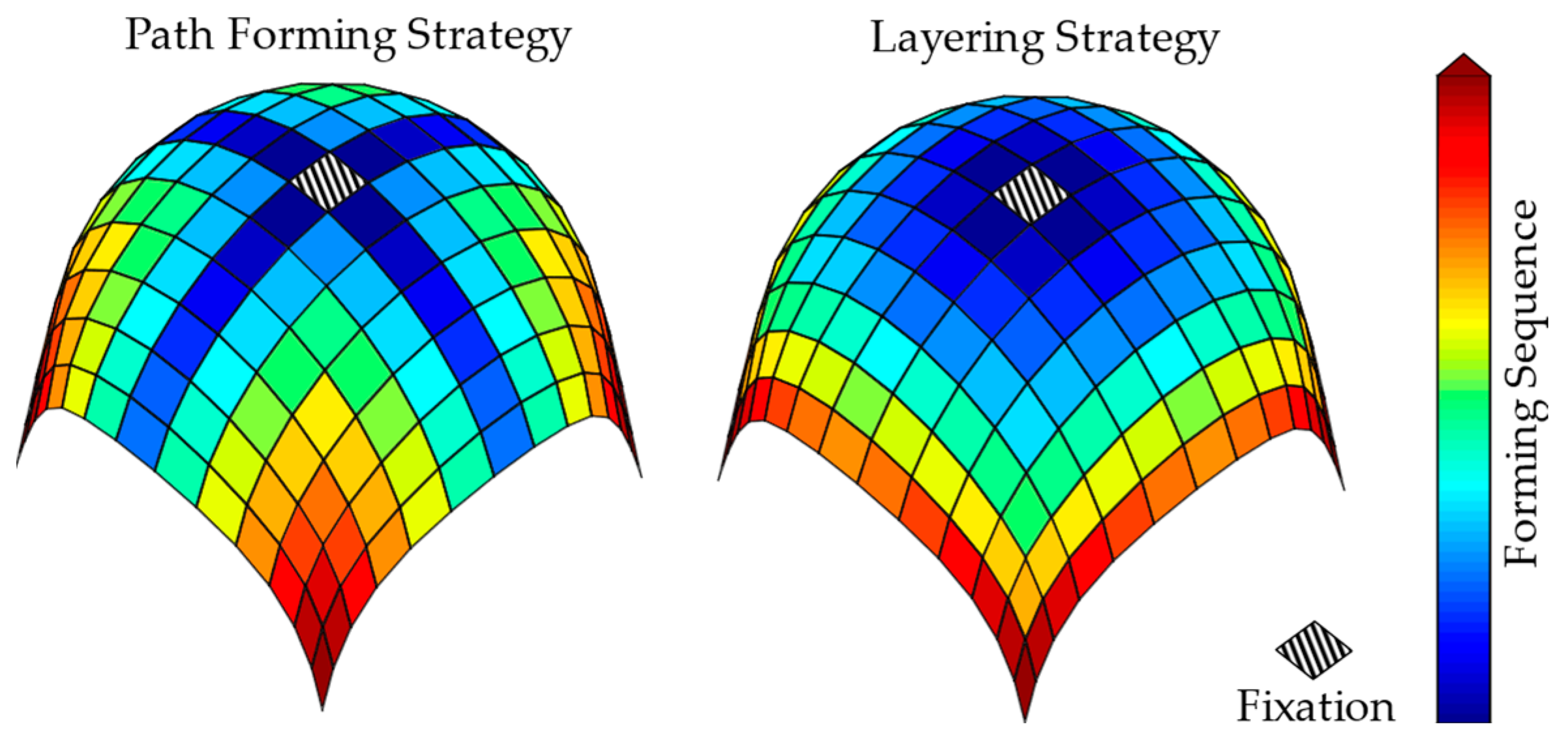
In a dieless process with as few tools as possible, a purely “local” draping approach is desirable. Thereby, the sequence of local draping operations is critical. Therefore, in [40], we developed a draping strategy for dieless forming of woven fibers, taking into account the shear distribution as primary sequencing criterion. Building upon the results of a kinematic draping simulation, areas are formed in order of ascending shear angle. The reason for this is that achieving a desired out-of-plane deformation (bending) seems considerably easier than generating a certain amount of in-plane deformation (shear). Furthermore, locally shearing a fabric will also introduce shear in surrounding areas, which is hardly reversible [40].
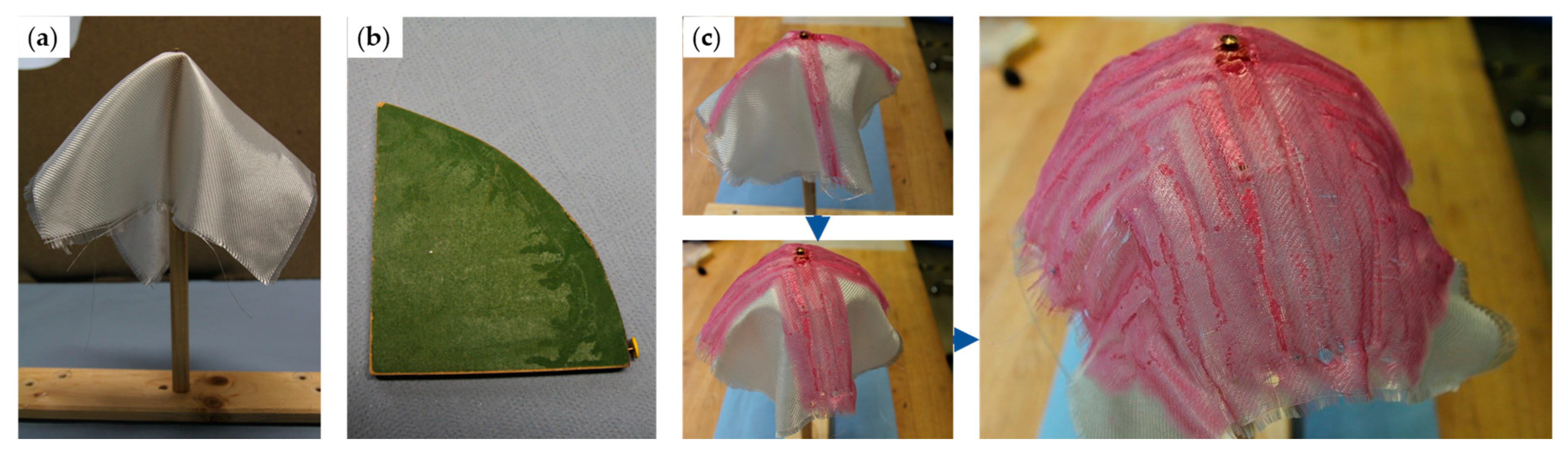
Two different principles were considered, as depicted in Figure 3. Either, forming is conducted in paths following the fiber orientations from a rigid starting point until the edge of the fabric, or the desired geometry is sliced in layers, within which the forming is sequenced in order of ascending shear [40].
In both approaches, bending the fibers is used for the introduction of shear as to eliminate the necessity of pulling on the fabric to introduce tension for in-plane deformation. Instead, as bending warp and weft yarns in the same direction will reduce the distance between their node points, compressive stresses are introduced in-plane into the area between them, which are relieved by deformation, such as shearing [40].

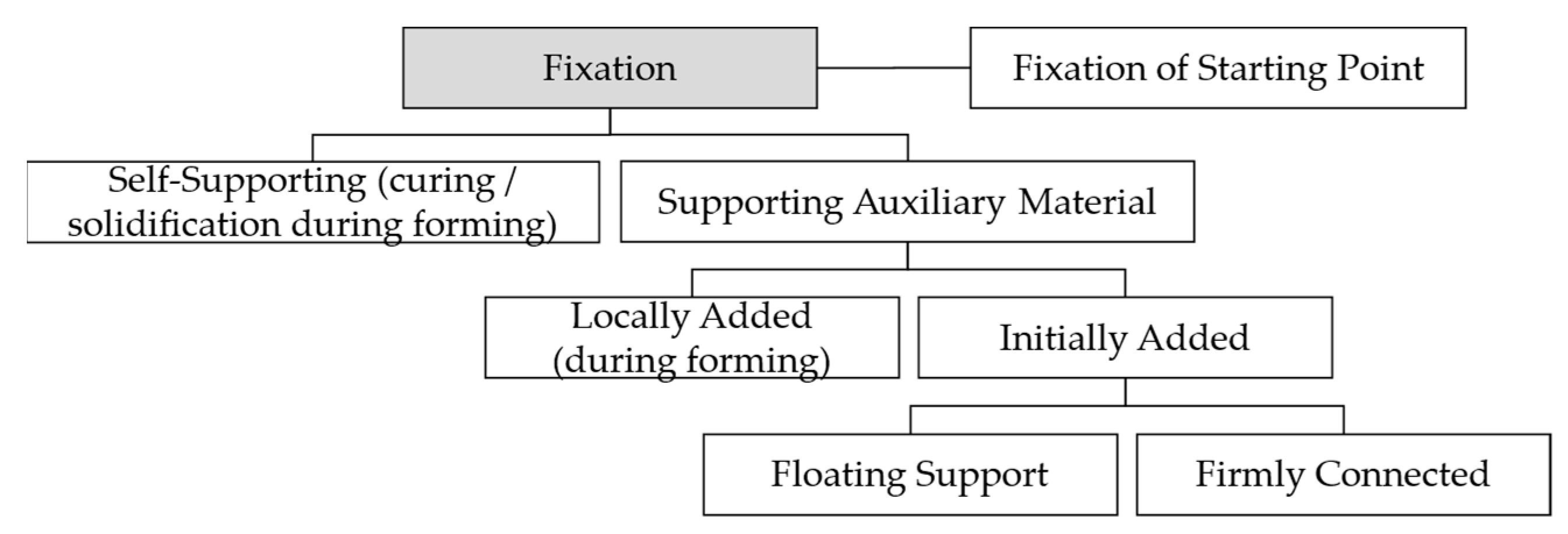
3.3. Fixation of the Fabric

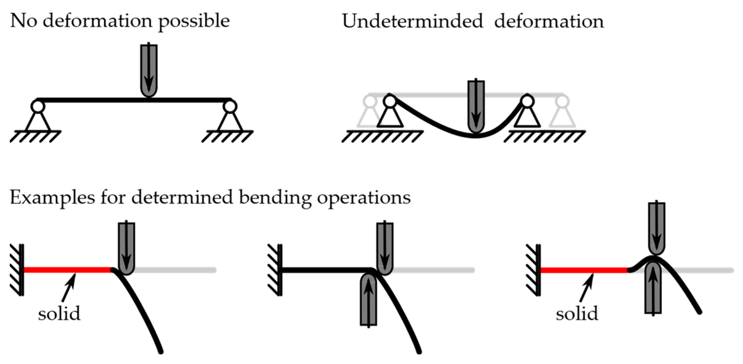
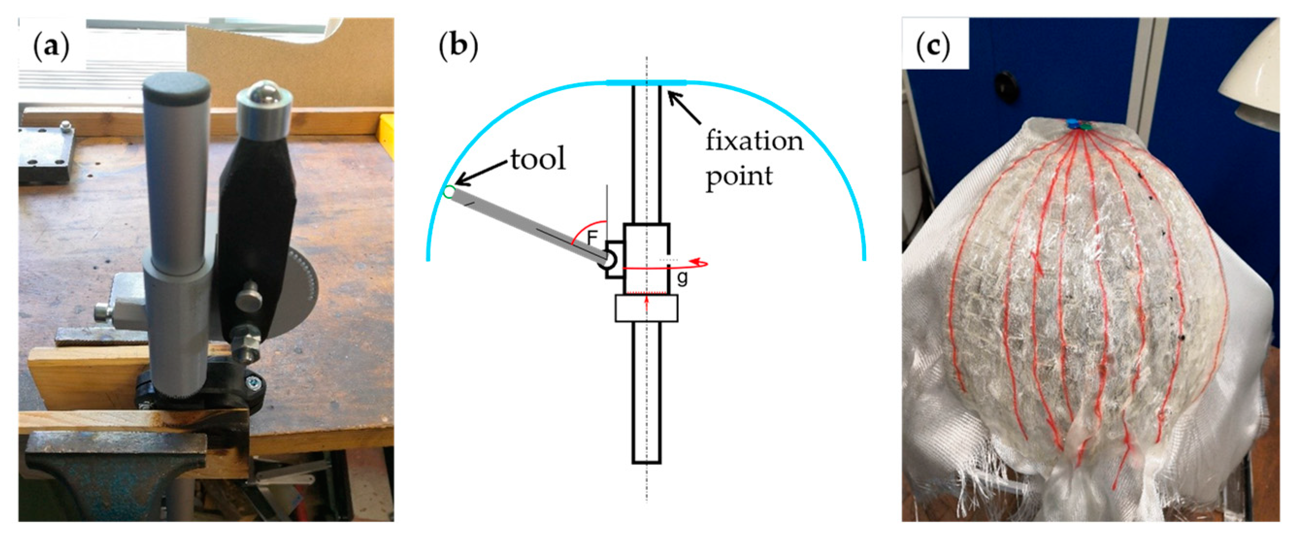
As mentioned above and depicted in Figure 4, a straight endless fiber cannot be deformed in between two fixedly clamped points, this including fixed solid or cured sections. On the other hand, using only a floating bearing of the fabric makes the draping process undetermined, as fibers could freely move in possibly undesired ways. Therefore, each bending operation, as described above, should take place between a fixed point or area of the respective tow and a free or floatingly supported edge. Thereby, the main desired deformation is introduced between the working point of the tool(s) and the fixation, while the remainder of the tow will undergo the necessary movement to enable this deformation, as visible in Figure 4. Due to the warp/weft-intersections, all crossing tows of the deforming yarn also need to be movable.
Both developed draping strategies comply with these prerequisites. Primarily, the starting point of the forming sequence, as emerged from the draping simulation, needs to be secured. For stability and realization of the clamping, e.g., through mechanical elements, the FRP must already be cured or solidified in this point. Due to the gradual approach, areas to be formed next are always adjacent to an already formed section. To maintain the shape and prevent redeformation during subsequent forming steps, a forming operation must include curing or solidification of the forming zone. Therefore, the solid processed area grows with each step, while the fixation of the starting point supports the formed material to a certain extent.
Alternatively, a supporting auxiliary material can be introduced to maintain the shape of flexible fabric, which is formed, but not yet cured or solidified. It could either be locally added in the process, or supporting the whole fabric from the outset. In that case, the auxiliary material must be able to selectively plasticly deform. Depending on the deformation behavior of this material, it can be either firmly connected to the whole fabric, or both must be able to slide on each other. In the latter case, at least the starting point of the draping needs to be firmly connected to the auxiliary material for determined draping. A feasible auxiliary material could be metal wire mesh, as it possesses the same deformation mechanisms as woven textiles, which are bending and shear [41].
The described alternatives for fixation are mapped in Figure 5.
Usage of a supporting material, or possibly additional clamping, could be especially required for highly flexible dry fabrics, in order to prevent unpredictable or undesirable draping when only fixed in the starting point. If the same happens to a pre-impregnated thermoset, it could stick onto itself, due to its tackiness. Owing to the lower flexibility of thermoplastic fibers, hybrid or commingled weaves are less likely to deform extremely undesirably when fixed. Semi-impregnated, and especially fully consolidated, thermoplastic FRPs are even better clampable at room temperature.

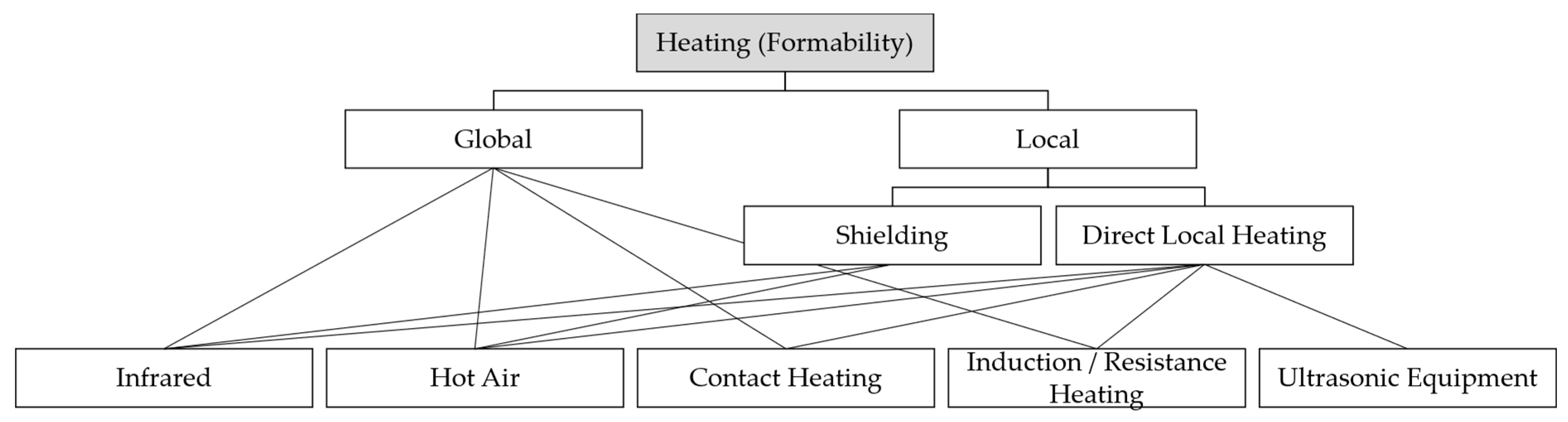
3.4. Acquiring Formability of Solid Matrix Material

A disadvantage of the solidity of many semi-impregnated, and all fully consolidated, thermoplastics is the necessity to heat them above glass-transition- or melting-temperature in order to allow deformation of the fabric. Thereby, if no support is used, already formed areas need to remain cold and solid, while others need to be hot and formable. As apparent from the draping strategy and the explanations above, the first forming operations require a major area of the sheet to be heated, while those areas are getting smaller during the process. Due to the fact that the first forming operations divide the sheet into individually drapable sections, the path-forming strategy is favorable in those cases.
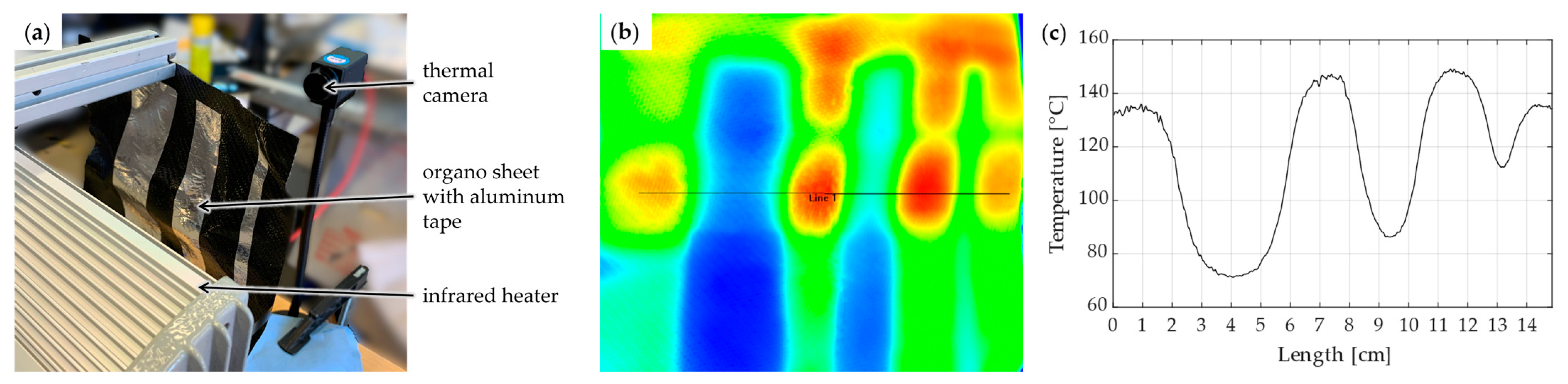
Targeted heating of a delimited area changing in size through each forming step could be realized by multiple different heat sources, including electrical heating with contacting elements or heat guns, gas torches, infrared heating and laser light sources, as well as ultrasonic elements. For electrically conductive carbon fibers, induction heating or direct resistance heating could be feasible as well. In order to localize heating of bigger heat sources, variable shielding could be used. This is especially feasible for infrared sources, as reflective material, such as aluminum adhesive film, could be applied to the areas of the sheet which should not be heated.
Figure 6 gives an overview of the described alternatives for global and local heating.

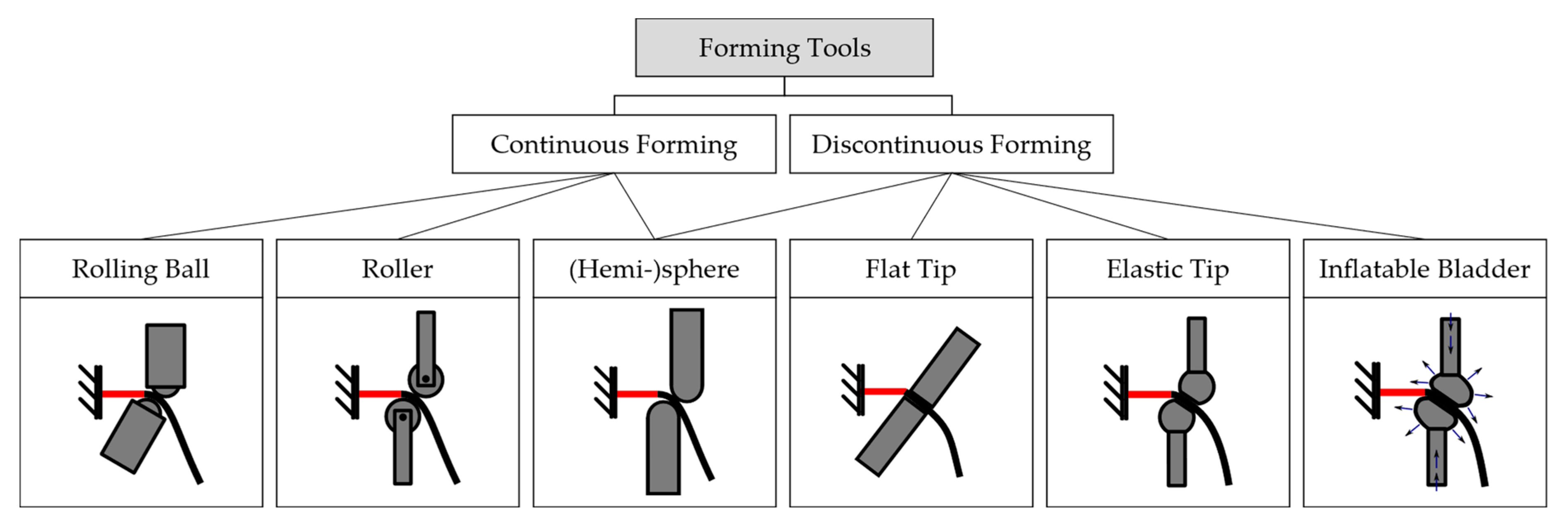
3.5. Forming Tools and Machines

Due to the flexibility of the fabric, two standard forming tools will be necessary in most cases, one on each side of the fabric. This is in order to support the textile against gravity, as well as the forming force from the other side, and to enable deformation in concave and convex directions without the need to reclamp the material. According to the forming strategy, the tools do not need to directly introduce tension into the fabric by pulling a fixed point. However, if support material with elastic-plastic deformation behavior, such as metal wire mesh, is used, the mesh needs to be bent sufficiently as to compensate for the elastic recovery.
For highest flexibility, the tools could be each guided by an industrial robot. However, cartesian machines would also be feasible if no tilting of the tool axis is required. Mounting the fabric fixture on a rotary positioner can facilitate accessibility for the tools.
The higher the degree of symmetry of the tool tips, the more advantageous it is for the accessibility and positioning. Therefore, tool tips could be hemispherical, rotating balls, rollers or similar. The radius of the tool tip defines the minimal formable edge radius of the part. Some processes, however, require the introduction of pressure into the composite for impregnation and consolidation (see below), which could also be realized by the tools. Therefore, elastic tools, flat tool tips or inflatable bladders might also be considered, in order to enlarge the pressurized area.
Depending on the tools, the forming can be continuous, for example, using rotatable tool tips, minimizing process time and friction, or discontinuous, for example, when adding one individual pressed area after another is required, moving the tools to the next forming point while not in contact with the part. Both concepts and their associated tool variants are depicted in Figure 7.

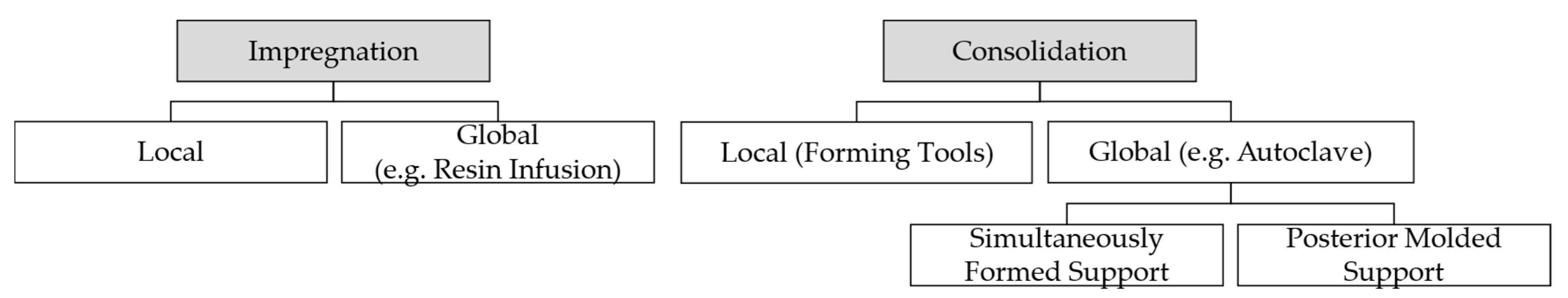
3.6. Impregnation and Consolidation

Separate, commingled and semi-impregnated materials require the (further) impregnation of the fibers with thermoset or thermoplastic matrices, meaning the wetting of all fibers. As explained above, this is especially challenging for thermoplastic polymers, which must first be heated above melting temperature, and yet have high viscosity, thus, likely deforming fibers or tows instead of fully wetting them during impregnation. The process is easier with shorter flow paths [36], so that the handling or transferring of a molten thermoplastic to a pre-heated fabric should be avoided.
During consolidation, pressure is applied on the composite to remove voids out of the matrix, set the correct fiber volume content and improve the surface quality of the part [36]. Higher matrix viscosity requires higher pressure for full impregnation and consolidation [42], which needs to be maintained for a certain time, especially in the case of thermoplastic matrices. Even pre-consolidated organo sheets benefit from the application of a certain pressure, as they tend to de-consolidate when heated above melting temperature for a specific time [43].
As explained above, the required pressing force could be generated by the handling devices and introduced into the fabric by the tools, locally consolidating the material in each forming step. This is comparable to the concept of in situ consolidation of thermoplastic matrices during automated layup processes, where heaters and compacting elements are used to locally consolidate the laid tapes [42]. Similar to acquiring formability (Section 3.4), different heat sources, such as contacting elements, infrared sources, lasers or ultrasonic heating, are feasible for impregnation and consolidation purposes. However, to produce a more homogenous part, full impregnation and consolidation using a global approach, for example, in a vacuum or autoclave setup, might be required in a separate processing step. In this case, an auxiliary material would be necessary to ensure that the formed shape of the part is maintained. This could be a simultaneously formed wire mesh, but also a negative mold that is rapidly molded from the dielessly formed component.
Figure 8 presents the described impregnation and consolidation alternatives.

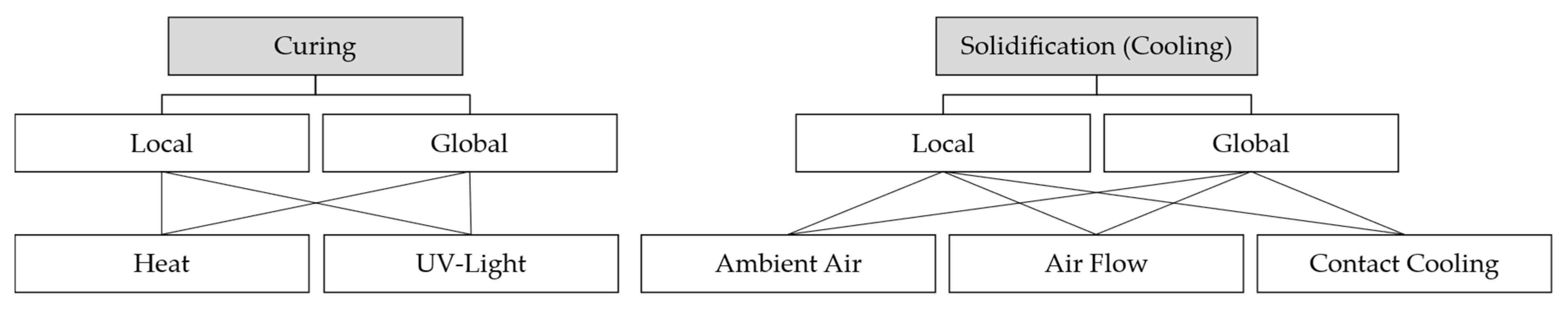
3.7. Curing or Solidification

Finally, thermoset polymers need to be cured and thermoplastics solidified to produce a solid part. Whether this process takes place locally while forming or globally in a final production step, or both, depends on the exact processing routes as discussed above.
Thermoplastic polymers solidify through cooling at ambient air or forced cooling through cold air flow or contacting elements, preferably under pressure, to maintain consolidation. Thermosets cure through chemical crosslinking, which, depending on the resin, can be initiated thermally or by UV-radiation. The latter process, called photopolymerization, is significantly faster, produces less styrene emissions and allows processing at atmospheric conditions, as well as easier resin handling [44]. Localized selective photopolymerization of pre-impregnated fabric could be enabled by a laser, while local impregnation also allows the usage of a conventional UV-light source. However, as carbon fibers block UV-light, this process would only allow glass fibers or additional thermo-curing, e.g., in a second processing step, would be necessary [44].
The variants for curing and solidification are visualized in Figure 9.

3.8. Allocation and Evaluation of the Processing Functions

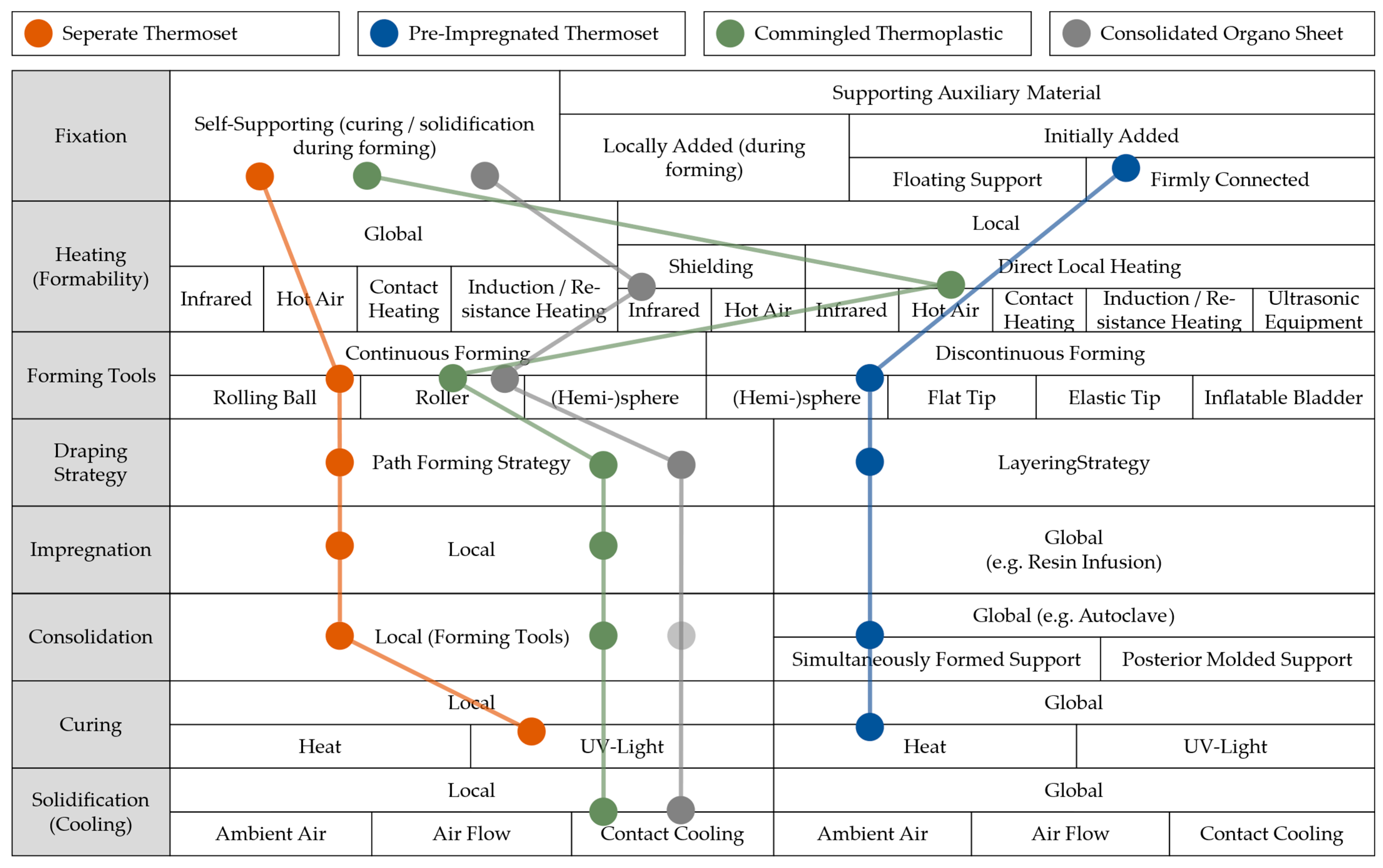
As elaborated, not all processing functions described above need to be realized for each of the different material types of Figure 2. Therefore, an allocation of processing functions to the material types is shown in Table 1. Additionally, a rating of the feasibility of performing a processing step on a material type from 1 (feasible) to 4 (hardly feasible) is introduced. Voids in the table indicate that a material type does not require a certain processing step, which corresponds to a rating of 0. The summed rating for each material type represents its unfeasibility. Consequently, the material types “dry fabric and thermoset”, “pre-impregnated thermoset”, “commingled thermoplastic” and “consolidated organo sheet” show highest feasibility and should be further considered and evaluated for dieless forming.

3.9. Process Route Conceptualization

In order to find possible processing routes for the four selected material types, the material types must be linked to the variants of the relevant process steps presented in Section 3.2, Section 3.3, Section 3.4, Section 3.5, Section 3.6 and Section 3.7. A morphological box, shown in Figure 10, is suitable for this purpose. As a multitude of different combinations seem feasible, only one processing route per material type is marked in the figure for simplicity. An example concept sketch of a setup for dieless forming of commingled thermoplastic fabric is depicted in Figure 11. Thereby, the woven fabric is clamped in the starting point on a rotatable fixation. For local impregnation, hot air heating is implemented, with a heat gun attached to the upper forming tool. Two cooled rollers, each guided by an industrial robot, are used for continuous forming according to the path-forming strategy. At the same time, the rollers consolidate and solidify the impregnated fibers, so that the processed fabric is self-supporting.

4. Practical Experiments

In the following, the four chosen processing routes are evaluated for practical feasibility in basic experiments.

4.1. Dry Fabric and Thermoset

4.1.1. Setup

Glass fiber twill weave with an areal weight of 160 g/m2 and a size of 30 × 30 cm2 was used to investigate local thermoset impregnation and UV-curing while forming a hemispherical shape. Therefore, the center of the fabric was locally impregnated and cured, before being clamped to a pole with a tack, while the remainder of the fabric was unsupported, as shown in Figure 12a.
In a first experiment, a wooden 2D quarter circle with a radius of 12 cm and a thickness of 1 cm, shown in Figure 12b, was used as a forming tool. It was coated with release agent before being manually positioned under the fabric to define a forming path according to the path-forming strategy. A brush was used to impregnate the fabric in this path with photopolymeric 3D-printing resin (PrimaCreator, Malmö, Sweden). Subsequently, a laser with a wavelength of 405 nm and a power of ~600 mW was manually guided along the path, exposing each spot of approx. 25 mm2 for 4 s to cure the resin. The tool was then moved to represent the next forming path, following the described strategy. The process was repeated until a full hemisphere was produced, as shown in Figure 12c.
In a second experiment, a rolling metal ball as a “1D” tool replaced the 2D tool in order to investigate full dieless forming in a setup representing the chosen processing route of the morphological box in Figure 10. The tool was mounted on the fixation pole, as shown in Figure 13a, and was manually movable along a hemispherical surface around the fabric fixation, illustrated in Figure 13b. Thus, the tool could be moved to the desired point, where the fabric between fixation and tool was impregnated and cured as explained above, using brush and laser, but avoiding contacting the tool with resin. Adding one formed and cured area to another, the path-forming strategy was followed, however realizing a discontinuous, instead of the desired continuous, forming approach.

4.1.2. Results

Both experiments demonstrated that the cured fabric areas were indeed sufficiently self-supporting, so that hemispheres could be generated as shown in Figure 12c and Figure 13c. However, surfaces were still tacky, so that further global UV-exposure would be required to fully cure the whole part. Overall, part quality was not satisfactory, as imprints of the tools were clearly visible in both parts. On the one hand, this is due to the inaccuracies of the manual processes. On the other hand, during local impregnation, the resin not only wetted the desired area, but was distributed somewhat further into the fabric by capillary forces, thus impregnating areas which were not supported. During subsequent UV-exposure, light conductivity of the glass fibers led to undesired curing of these areas surrounding the laser spot, including resin which was in contact with the tool, leading to adhesion.

4.2. Pre-Impregnated Thermoset

4.2.1. Setup

Plain woven stainless steel 1.4301 wire mesh with 0.56 mm wire diameter and 3.15 mm mesh size was selected as a supporting material for simultaneous deformation with woven prepreg material. However, in a first setup, dry glass fiber fabric was used to investigate feasibility of simultaneous forming. Therefore, 25 × 25 cm2 glass fiber twill weave with an areal weight of 160 g/m2 was placed on a wire mesh of the same size and affixed to it in 9 points with adhesive. The setup was then centrally clamped between two poles, as depicted in Figure 14a. During evaluation of dieless wire mesh forming in [41], we found that the layering strategy is most suitable, as lower forming force is required and (discontinuous) forming is more symmetric compared to the path-forming strategy. Therefore, dieless forming with two handheld steel tools with hemispherical tips, shown in Figure 14b, was performed according to the discontinuous layering strategy approach. With one tool on each side of the layup, the mesh was bent sufficiently as to retain the desired amount of plastic deformation of the metal wires. After forming a hemispherical shape of approx. 20 cm diameter, as presented in Figure 14c, the fabric was impregnated with thermoset resin using a brush. Again, deviating from the processing route envisioned in the morphological box in Figure 10, the same photopolymeric resin as in the previous experiments in Section 4.1.1 was used. After the layup was placed under an UV lamp for 20 min, the cured FRP could be manually separated from the wire mesh with moderate force, with the resulting part shown in Figure 14d.
In a second experiment, in order to investigate forming of an already impregnated fabric, 16 × 16 cm2 of the same woven glass fiber fabric was placed on a wire mesh of matching size and then impregnated with the same thermoset resin as before using a brush. The layup was placed in a polyethylene/polyamide vacuum bag of 160 µm thickness and evacuated to approx. −850 mbar, as to firmly connect the fiber fabric and supporting wire mesh during forming, as well as to provide for global consolidation and protect the tools from resin. To prevent perforation of the bag during forming, the edges of the wire mesh were covered with adhesive tape beforehand. The setup was then centrally clamped between two poles, as depicted in Figure 15a. After forming a hemispherical frustum of approx. 20 cm diameter using the same tools and strategy as above, presented in Figure 15b, the vacuum bag was placed under a UV lamp for 20 min. Subsequently, the bag was opened and the cured FRP separated from the wire mesh, with the resulting part shown in Figure 15c.

4.2.2. Results

The first experiment especially demonstrated the good suitability of metal wire mesh as a supporting material for dieless forming. While a wrinkle-free hemisphere was effectively produced in the first setup, forming of prepreg and wire mesh in a vacuum bag was less successful. Thereby, pure bending of the 2D layup did not pose a challenge, but the relatively thick and firm vacuum bag prevented the introduction of shear into fabric and mesh. Therefore, severe wrinkles developed, which are also evident in the final cured part in Figure 15c. As a conclusion, locally fixating fabric to wire mesh through interweaving, an adhesive, as in the first experiment, or a more suitable, stretchable vacuum setup is required to provide connection and transmission of the draping mechanisms during dieless forming. Furthermore, as visible in Figure 14d and Figure 15c, the absence of a smoothing layer results in clear imprints of the wire mesh in the cured FRPs.

4.3. Commingled Thermoplastic

4.3.1. Setup

In a setup similar to Section 4.1.1, 30 × 30 cm2 glass fiber / polypropylene commingled twill weave fabric (COMFIL, Gjern, Denmark), with an areal weight of 700 g/m2 and 60 % reinforcement weight fraction, was centrally clamped to a pole with a tack, as shown in Figure 16b. The 2D quarter circle, coated with release film, was used as a tool representing the forming path. After the tool was manually placed to support the fabric, an area of approx. 1 cm2 was heated by a hot air gun with 2 kW, set to ~500 °C, as shown in Figure 16c. After 6 s, a temperature of ~190 °C was reached, as measured by a pyrometer, and the polypropylene melted and impregnated the glass fibers. The heating was then disabled and a roller covered in release film was firmly pressed onto the fabric by hand, consolidating the material between the quarter circle tool and roller tool, depicted in Figure 16d. The roller, as well as the FRP, were cooled by an air jet to solidify the material. This way, it was proceeded moving along the forming path. The same was repeated with the other forming paths as set according to the path-forming strategy, until a hemisphere was formed.
A further experiment, in which the 2D tool was replaced by a second roller to investigate dieless forming, was conducted in a very similar setup. The fabric, of 25 × 25 cm2 size, was clamped between two poles, as shown in Figure 17a, and two handheld rollers, as depicted in Figure 17b, one on each side of the fabric, were used to form and consolidate the material by applying moderate pressure between them. As the tools were moved along the forming paths to form a hemisphere of approx. 20 cm diameter, according to the path forming strategy presented in Figure 17c, the hot air gun was used to heat the polymer and a cold air jet was used to cool the upper roller and the FRP, just as in the previous experiment.

4.3.2. Results

As evident in Figure 17c, the local impregnation, consolidation and solidification produced rigid material so that the FRP was able to support itself during the forming process. The final produced hemispheres are depicted in Figure 18a,c for the 2D and 1D tool forming, respectively. Both processes were able to achieve sufficient shear in the fabric in order to drape the hemispheres correctly. However, due to the manual procedures, a somewhat wavy surface has been created, and geometric accuracy could be improved. Based on the appearance of the surface quality, consolidation was slightly more successful when the 2D quarter circle tool was used. This could be due to the bigger area that was pressed at once, but could also be due to an increased remelting effect when manually forming the fabric with two roller tools. As can be seen by the example of an intermediate forming step during 2D tool-forming in Figure 18b, the tools initially created a relatively smooth surface in each forming path. However, when an adjacent path was processed, the just-consolidated material was partially melted again, as heating with the hot air gun was not as localized as required. This remelting without reconsolidation resulted in an inferior surface quality.

4.4. Consolidated Organo Sheet

4.4.1. Aluminum Tape Shielding

Feasibility of using aluminum adhesive tape to shield an already deformed organo sheet from infrared radiation was tested in a setup depicted in Figure 19a. A two-layered twill weave carbon fiber organo sheet (INEOS Styrolution, Frankfurt am Main, Germany), sized 25 × 25 cm2 with styrene-acrylonitrile matrix, an areal weight of 245 g/m2, 45% fiber volume content and a thickness of 0.6 mm, was partially taped with reflective aluminum adhesive tape (tesa, Hamburg, Germany) of 5, 3 and 1 cm width in three parallel stripes. The sheet was clamped in a distance of 20 cm in front of a 2 kW infrared heater, with the taped side facing the heater. Due to an initial deformation already present in the organo sheet in the form of a horizontal trough of 5 cm depth, the minimum distance to the front of the heater was approx. 15 cm. An infrared camera (FLIR A65, FLIR Systems, Wilsonville, OR, USA) was placed to view the backside of the sheet and measure the temperature distribution with an emission coefficient of 1. The infrared image, after a heating time of 60 s, is shown in Figure 19b, while Figure 19c gives a plot of the temperature distribution in the line indicated in Figure 19b, which is the line of minimal distance to the infrared heater.
As evident from Figure 19b, temperature distribution in a deformed sheet is inhomogeneous, due to the dependency of heating on the distance to the infrared source and the surface angle relative to the incoming radiation. The main finding, however, is that the aluminum tape provides a good means to localize infrared heating of an organo sheet. The temperature difference between exposed and shielded areas increases with higher width of the tape; however, even a stripe of tape with 1 cm width caters for a temperature difference of 30–40 °C. This can be sufficient to keep formed areas below glass transition or melting temperature, so that taped areas maintain their shape while others are being formed.

4.4.2. Forming Setup

In a preliminary forming setup, a four-layered twill weave carbon fiber organo sheet (INEOS Styrolution, Germany), sized 25 × 25 cm2 with styrene-acrylonitrile matrix, an areal weight of 245 g/m2, 45 % fiber volume content and a thickness of 1.2 mm, was used to investigate the forming strategy. The starting point of the forming paths was fixed to the top of a hemispherical mold of 20 cm diameter, and half the sheet was heated by a 2 kW infrared heater, as depicted in Figure 20a. The temperature was measured using a pyrometer. After reaching 180 °C, the heating was disabled and a path was formed by a handheld PTFE roller applying moderate pressure. During forming, the roller, as well as the sheet exiting the roller, were cooled using an air jet. Afterwards, the just-formed path was masked with reflective aluminum adhesive tape (tesa, Hamburg, Germany) in order to maintain the formed geometry during the next heating step. Repeating this process, a hemisphere was formed according to the path-forming strategy, as shown in Figure 20b–d.
In order to investigate dieless forming, an organo sheet of the same type, but single-layered, with a thickness of 0.3 mm and a size of 25 × 25 cm2, was centrally clamped between two poles. As presented in Figure 21a, a 2 kW infrared heater was installed on each side of the sheet, in order to heat half the FRTP to approx. 180 °C. Once the matrix was formable, heating was removed and two handheld rollers, depicted in Figure 17b, were guided along a forming path, one on each side of the sheet. During forming, the top roller, as well as the material exiting the forming zone, were cooled with an air jet. The formed path was then covered with aluminum adhesive tape on both sides, as shown in Figure 21b, so that the process could be repeated for the next path without destroying the formed shape. This way, a hemispherical frustum, of approx. 20 cm diameter and 5 cm height, shown in Figure 21b, and a hemisphere of approx. 20 cm diameter, shown in Figure 21c, were formed.

4.4.3. Forming Results

Comparing Figure 20d and Figure 21c, organo sheet-forming with a one-sided mold produced a more accurate hemisphere than manual dieless forming. While the development of wrinkles could not be avoided in either process, they were considerably fewer and smaller when a mold was used. Thereby, the rather high sheet thickness of four layers, in combination with one-sided heating, resulted in lower drapability. Due to the inhomogeneous temperature distribution in an already deformed sheet, as discussed in Section 4.1.1, deformation behavior can be different within the heated area, resulting in the formation of wrinkles.
In dieless forming, drapability was increased by reducing the sheet thickness to one layer and using double-sided heating. However, the problems associated with inhomogeneous temperature distribution remained. In combination with the inaccuracies of manual processing, correct shape reproduction was hindered in both dieless trials.
The main finding of the experiments was that formed paths shielded by aluminum tape indeed remained rigid and provided stability to the part during forming. In addition, the air jet assistance was successful in rapidly and locally cooling the formed path. This way, the path-forming strategy could be followed and a certain amount of shear introduced to form hemispherical shapes.

5. Discussion and Outlook

A potential way to lower costs, save time and decrease the effort required for producing prototypes, single parts and small batches of fiber-reinforced plastics is to realize dieless forming with basic standard tools controlled by handling devices, such as industrial robots. With the aim of advancing research in this field, a systematic functional analysis was conducted to find and evaluate processing methods for different material and product type combinations. Options for fixation, acquiring formability, forming, impregnation, consolidation, curing and solidification were discussed for eight different categories of woven FRP semi-finished products, including dry fabric to be impregnated with thermoset matrix, fabric pre-impregnated with thermoset, woven commingled thermoplastic and reinforcement fiber yarns, as well as consolidated thermoplastic organo sheets. Those four product types were rated most feasible for dieless forming through theoretic considerations and thus further elaborated by finding possible processing routes in a morphological box. Although many different process combinations are possible and worth investigating, focus was laid on:
  • local forming, impregnation and photopolymerization of thermoset resin;
  • dieless forming of thermoset prepreg, together with metal wire mesh support material and subsequent global curing;
  • local forming, impregnation, consolidation and solidification of thermoplastic commingled yarn fabric;
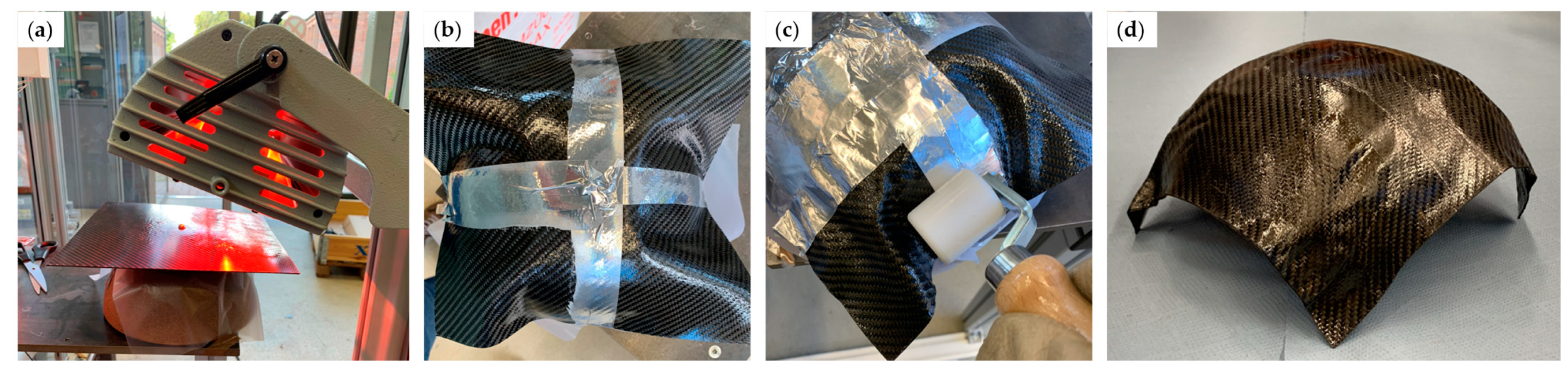
  • targeted infrared heating through aluminum tape shielding, local forming and solidification of organo sheets.
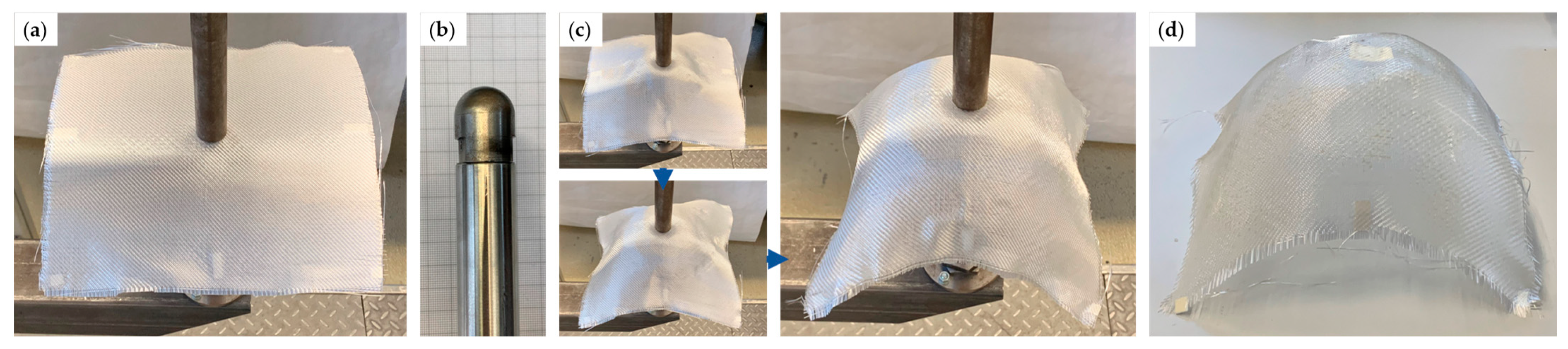
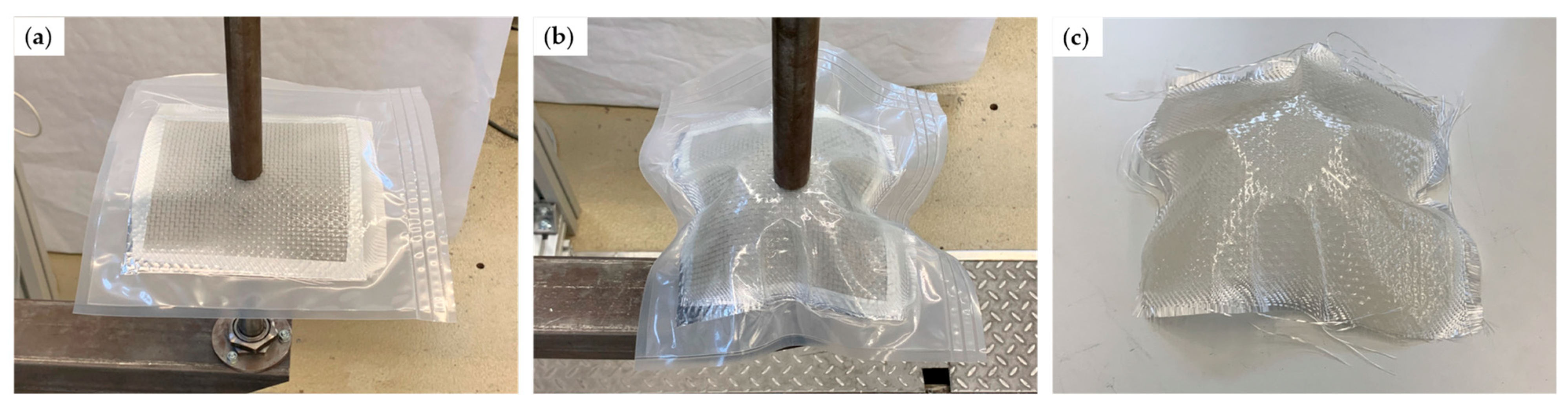
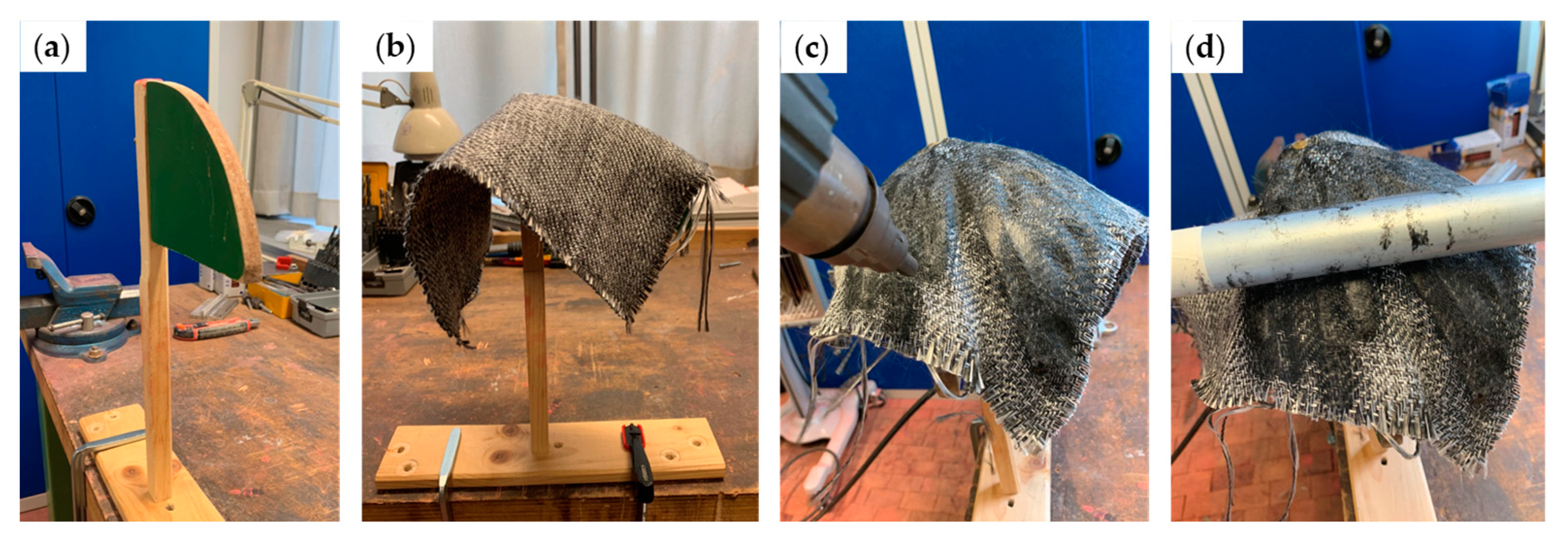
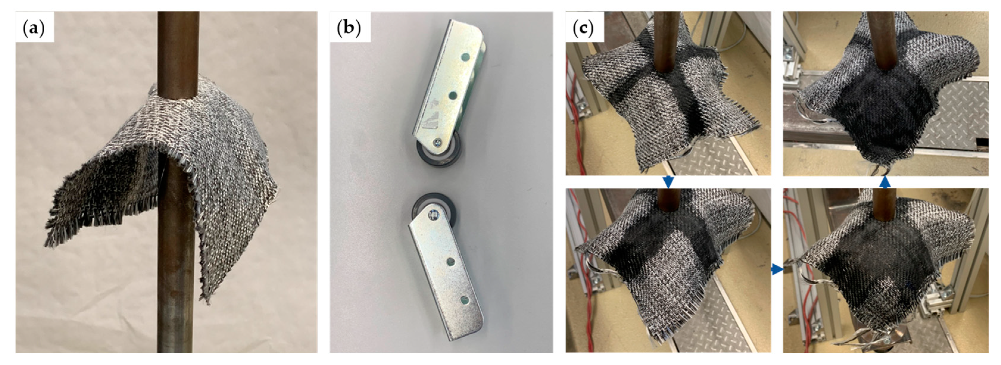
These processing routes were investigated in basic forming experiments using first 2D or 3D tools, before increasing complexity and reverting to manually guided “1D” tools for dieless forming, including rolling balls, rollers and hemispherical tool tips. Although each experiment was repeated only once and all tests were carried out by hand, strictly following the developed draping strategies, the desired qualitative results were generated. These were to prove the general functionality of the envisioned processes and to gain insight into general material behaviors, important processing parameters and requirements for further development.
The main challenge of local forming is the maintaining of already formed shapes while allowing drapability of remaining areas. Therefore, one of the key findings of the experiments is that local thermoset curing (1), metal wire mesh support (2), local thermoplastic impregnation and solidification (3), as well as aluminum tape shielding (4) were able to provide sufficient stability to formed areas and thus met this requirement. However, clear differences in overall process capabilities could be observed:
Although laser-based UV-radiation provides a good means of rapid local curing, the high-viscosity resin wetted unwanted areas of the fabric, which were then cured, due to light conductivity of the used glass fibers. Thereby, undefined geometries were captured and tools in contact with this respective resin adhered to the surface, all in all deteriorating shape accuracy and part quality. Furthermore, danger of the laser radiation and toxicity of the resin requires high safety measures, and photopolymerization is not suitable for carbon FRPs.
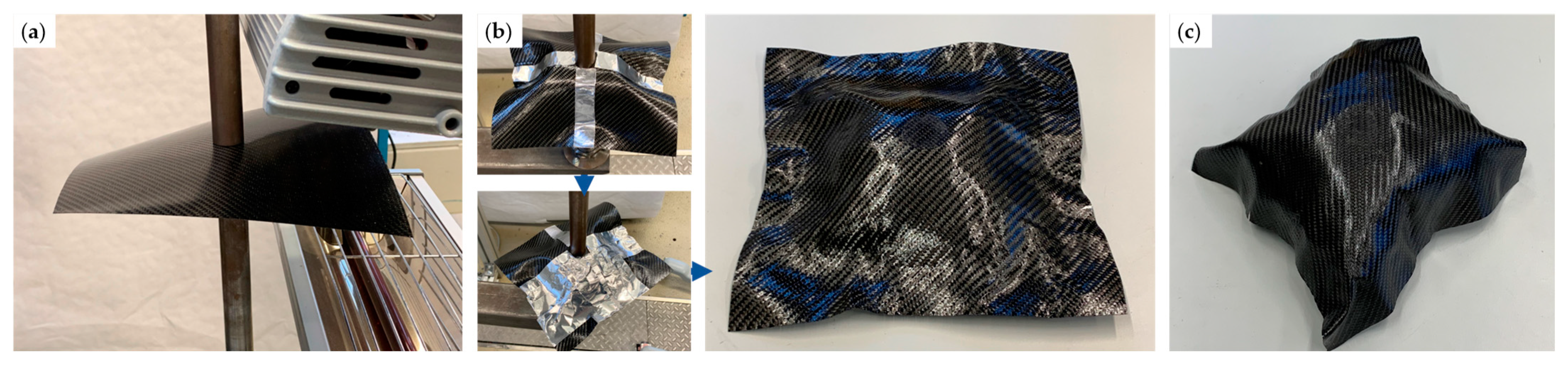
Metal wire mesh is a well-suitable support material as it possesses the same draping mechanisms as woven fibers, but can be plasticly deformed. However, to transfer this deformation to the fiber fabric, a temporary bond between the two materials needs to be established. While later soluble adhesive seems to be most feasible according to the experimental results, a flexible and stretchable vacuum bag enclosing the layup could ensure sufficient contact pressure and simultaneously aid in consolidation. Just like the vacuum bag, a smoothing sheet preventing imprints of the wire mesh on the final part needs to be able to shear together with the fibers and wires. Another option would be to functionally and structurally integrate metal wires and FRP, similar to the composite in [46], or FRP with lightning protection in aerospace applications [47].
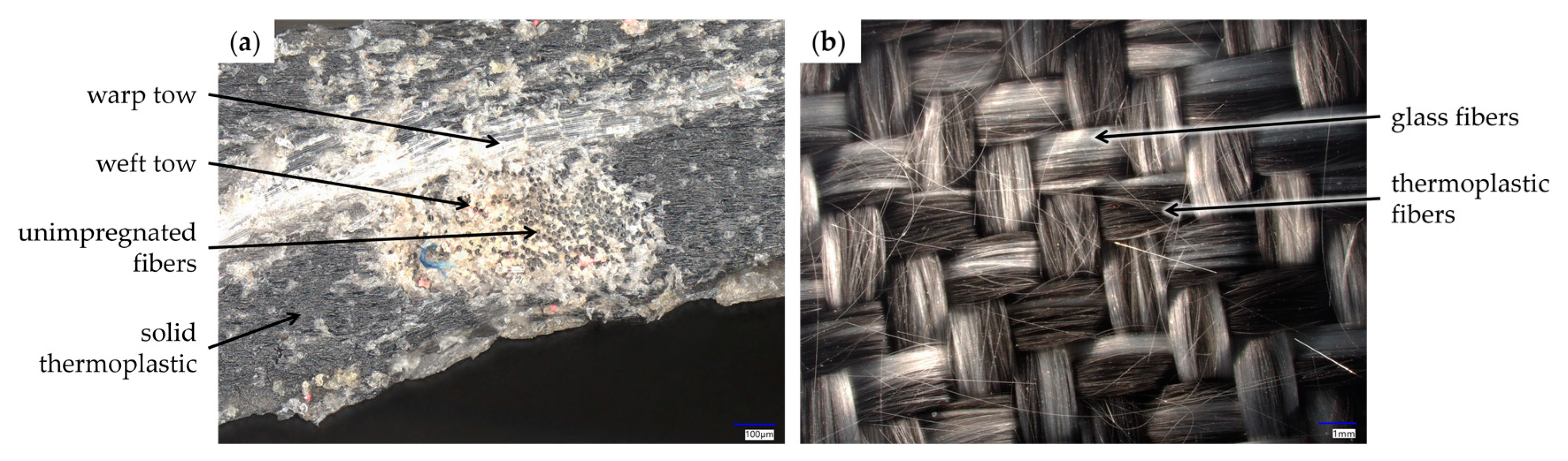
Commingled thermoplastic-forming benefits from good drapability of the woven fibers, while local impregnation and consolidation proved challenging. On the one hand, heating for impregnation must be more localized than achievable with the setup used, while on the other hand, the pressed area might be too small, and pressing duration too short, to achieve a sufficient degree of impregnation and consolidation in a reasonable process time. Although not the focus of this work, initial investigations of internal component quality were conducted, cutting a pressed area and examining the cross section under a video microscope (Keyence, Osaka, Japan). As shown in Figure 22a, individual glass fiber tows are still visible, whose inner fibers are not impregnated with thermoplastic. However, as a microscope image of the untreated surface of the commingled yarn fabric in Figure 22b shows, the degree of intermingling of individual fibers is already quite low in the initial state, with rather individual glass fiber and thermoplastic yarns alongside each other. Still, further investigations on different heating and tooling options and materials, as well as process windows for local impregnation and consolidation, are necessary to determine whether further global impregnation and consolidation might be required as a post-processing step.
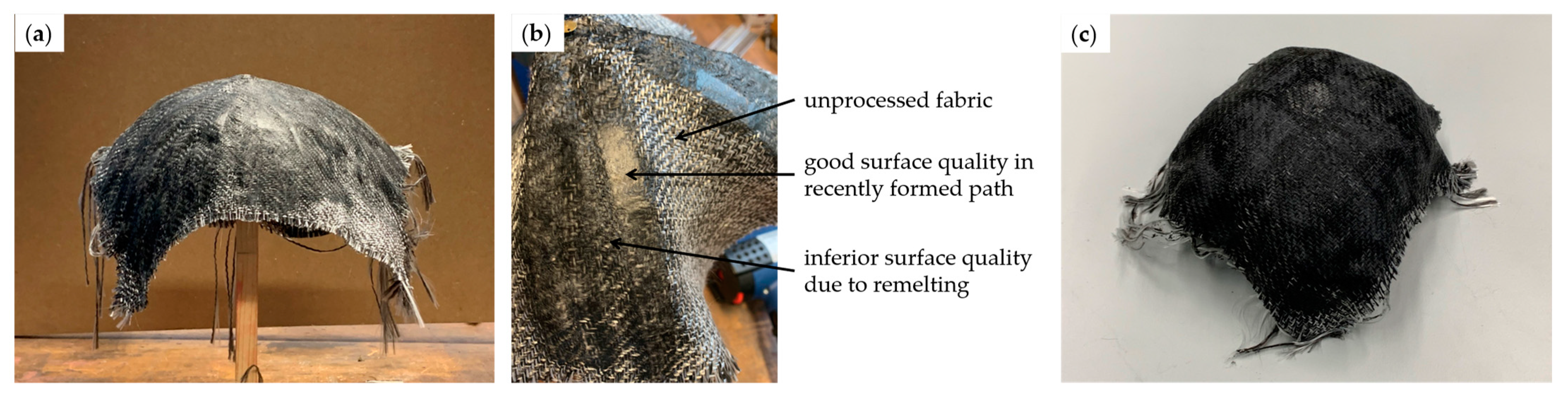
Finally, consolidated thermoplastic organo sheets provide high stability in clamped and cold areas, and are advantageous regarding final part quality when carefully formed and not de-consolidated. To avoid multiple repeated heating, as conducted in the experiments, which can have negative effects on material properties, direct application of the shielding aluminum tape by the forming tool rollers would be beneficial. Additionally, infrared heating needs to be improved to allow uniform local heating not only of a flat sheet, but also of areas which already have been deformed. It then has to be investigated if drapability of the heated areas is sufficient for a successful application of the path-forming strategy, which was not yet the case in the conducted trials.
All in all, commingled thermoplastic forming, as well as metal wire mesh-supported forming, proved to be the overall most feasible options of dieless FRP production, best uniting stability of formed areas and drapability of to-be-deformed areas. A combination of both approaches seams feasible as well, as local impregnation and solidification of commingled fabric during wire mesh-supported forming would again increase the stability of formed areas. Similarly, the wire mesh would allow global impregnation, consolidation and solidification, for example, in a vacuum setup, after forming. As presented in [41], metal mesh support can be used for organo sheet-forming as well, with possibilities to realize electrical resistance heating through the wires.
Building upon this fundamental study, further research is necessary on the deformation behavior of the different material combinations, including the development of simulation capabilities, in order to automatically generate appropriate forming paths and the determination of forming limits. These are influenced, not only by the tool geometries, limiting the minimum radius of part features, but also by the plastic deformation limit of eventual support material and the shearability of the woven fibers using the developed draping strategy. However, geometric forming limits introduced by the mold itself, such as problems with undercuts or undesired adhesion of fabric to the mold, could be eliminated in a dieless process. Regarding the technical implementation, further studies on forming tools and heating options can be conducted. Last, but not least, systematic and quantitative investigations on achievable part qualities are necessary. These include microscopic investigations, as touched upon above, to determine internal part qualities, such as the degree of impregnation, porosity, crystallinity and fiber volume content, as well as studies on mechanical properties and shape accuracies. To enable these assessments, technical implementations of the processes with automated handling devices, providing repeatable quality, need to be realized.

Author Contributions

Conceptualization, J.-E.R., R.G. and T.S.; methodology, J.-E.R.; formal analysis, J.-E.R. and R.G.; investigation, J.-E.R.; writing—original draft preparation, J.-E.R.; writing—review and editing, R.G. and T.S.; visualization, J.-E.R. and R.G.; supervision, T.S.; project administration, T.S.; funding acquisition, T.S. All authors have read and agreed to the published version of the manuscript.

Funding

This research was funded by the German Federal Ministry for Economic Affairs and Climate Action under the Program LuFo VI-1 iFish, grant number 20Q1917C.

Data Availability Statement

Not applicable.

Conflicts of Interest

The authors declare no conflict of interest. The funders had no role in the design of the study; in the collection, analyses, or interpretation of data; in the writing of the manuscript; or in the decision to publish the results.

References

  1. Ehrenstein, G. Faserverbund-Kunststoffe; Hanser Verlag: Munich, Germany, 2006. [Google Scholar]
  2. Clyne, T.W.; Hull, D. An Introduction to Composite Materials; Cambridge University Press: Cambridge, UK, 2012; ISBN 9780521381901. [Google Scholar]
  3. Mallick, P. Fiber-Reinforced Composites: Materials, Manufacturing and Design; CRC Press: Boca Raton, FL, USA, 2008. [Google Scholar]
  4. May, D. Integrierte Produktentwicklung mit Faser-Kunststoff-Verbunden; Springer: Berlin, Germany, 2020; ISBN 978-3-662-60285-0. [Google Scholar]
  5. Chawla, K.K. Composite Materials: Science and Engineering; Springer: Berlin, Germany, 2012. [Google Scholar]
  6. Flemming, M.; Ziegmann, G.; Roth, S. Faserverbundbauweisen: Fertigungsverfahren Mit duroplastischer Matrix; Springer: Berlin, Germany, 1996. [Google Scholar]
  7. Zindani, D.; Kumar, K. An insight into additive manufacturing of fiber reinforced polymer composite. Int. J. Lightweight Mater. Manuf. 2019, 2, 267–278. [Google Scholar] [CrossRef]
  8. Bannister, M. Challenges for composites into the next millennium—A reinforcement perspective. Compos. A Appl. Sci. Manuf. 2001, 32, 901–910. [Google Scholar] [CrossRef]
  9. Rosochowski, A.; Matuszak, A. Rapid tooling: The state of the art. J. Mater. Process. Technol. 2000, 106, 191–198. [Google Scholar] [CrossRef]
  10. Poodts, E.; Minak, G. Application of rapid tooling for the production of moulds suitable for autoclave forming of CFRP. Rapid Prototyp. J. 2013, 19, 327–336. [Google Scholar] [CrossRef]
  11. Rajkumar, V.; Nahaad, V.; Felix, R. Design and Robotic Fabrication of 3D Printed Moulds for Composites. In Proceedings of the 29th Annual International Solid Freeform Fabrication Symposium—An Additive Manufacturing Conference, Austin, TX, USA, 13–15 August 2018. [Google Scholar]
  12. Sudbury, T.Z.; Springfield, R.; Kunc, V.; Duty, C. An assessment of additive manufactured molds for hand-laid fiber reinforced composites. Int. J. Adv. Manuf. Technol. 2017, 90, 1659–1664. [Google Scholar] [CrossRef]
  13. Afonso, D.; Alves de Sousa, R.; Torcato, R.; Pires, L. Incremental Forming as a Rapid Tooling Process; Springer International Publishing: Cham, Switzerland, 2019; ISBN 978-3-030-15359-5. [Google Scholar]
  14. Fiorotto, M.; Sorgente, M.; Lucchetta, G. Preliminary studies on single point incremental forming for composite materials. Int. J. Mater. Form. 2010, 3, 951–954. [Google Scholar] [CrossRef]
  15. Trzepieciński, T. Recent Developments and Trends in Sheet Metal Forming. Metals 2020, 10, 779. [Google Scholar] [CrossRef]
  16. Ben Said, L. The incremental sheet forming; technology, modeling and formability: A brief review. Inst. Mech. Eng. Part E J. Process Mech. Eng. 2022, 236, 2729–2755. [Google Scholar] [CrossRef]
  17. Kaufman, S.G.; Spletzer, B.L.; Guess, T.L. Freeform fabrication of polymer-matrix composite structures. In Proceedings of the International Conference on Robotics and Automation, Albuquerque, NM, USA, 25–25 April 1997; pp. 317–322. [Google Scholar]
  18. Walczyk, D.F.; Hosford, J.F.; Papazian, J.M. Using Reconfigurable Tooling and Surface Heating for Incremental Forming of Composite Aircraft Parts. J. Manuf. Sci. Eng. 2003, 125, 333–343. [Google Scholar] [CrossRef]
  19. Miller, A.K.; Gur, M.; Peled, A.; Payne, A.; Menzel, E. Die-Less Forming of Thermoplastic- Matrix, Continuous-Fiber Composites. J. Compos. Mater. 1990, 24, 346–381. [Google Scholar] [CrossRef]
  20. Brent Strong, A.; Hauwiller, P.B. Incremental Forming of Large Thermoplastic Composites. J. Thermoplast. Compos. Mater. 1989, 2, 122–132. [Google Scholar] [CrossRef]
  21. Cedeno-Campos, V.M.; Jaramillo, P.A.; Fernyhough, C.M.; Fairclough, J.P.A. Towards mould free composites manufacturing of thermoset prepregs. Incremental curing with localised pressure-heat (ICULPH). Procedia CIRP 2019, 85, 237–242. [Google Scholar] [CrossRef]
  22. Xiao, X.; Kim, J.-J.; Oh, S.-H.; Kim, Y.-S. Study on the incremental sheet forming of CFRP sheet. Compos. A Appl. Sci. Manuf. 2021, 141, 106209. [Google Scholar] [CrossRef]
  23. Zhu, H.; Ou, H.; Popov, A. Incremental sheet forming of thermoplastics: A review. Int. J. Adv. Manuf. Technol. 2020, 111, 565–587. [Google Scholar] [CrossRef]
  24. Ikari, T.; Tanaka, H.; Asakawa, N. Development of a Novel Shell Shaping Method with CFRTP: Forming Experiment Using Localized Heating in Processing Point. MSF 2016, 874, 40–45. [Google Scholar] [CrossRef]
  25. Conte, R.; Ambrogio, G.; Pulice, D.; Gagliardi, F.; Filice, L. Incremental Sheet Forming of a Composite Made of Thermoplastic Matrix and Glass-Fiber Reinforcement. Procedia Eng. 2017, 207, 819–824. [Google Scholar] [CrossRef]
  26. Torres, S.; Ortega, R.; Acosta, P.; Calderón, E. Hot Incremental Forming of Biocomposites Developed from Linen Fibres and a Thermoplastic Matrix. SV-JME 2021, 67, 123–132. [Google Scholar] [CrossRef]
  27. Bagheri, S.; Kami, A.; Shakouri, M. Single point incremental forming of polyamide/30 wt% short glass fiber composite. J. Thermoplast. Compos. Mater. 2022, 0, 1–14. [Google Scholar] [CrossRef]
  28. Ambrogio, G.; Conte, R.; Gagliardi, F.; de Napoli, L.; Filice, L.; Russo, P. A new approach for forming polymeric composite structures. Compos. Struct. 2018, 204, 445–453. [Google Scholar] [CrossRef]
  29. Al-Obaidi, A.; Graf, A.; Kräusel, V.; Trautmann, M. Heat supported single point incremental forming of hybrid laminates for orthopedic applications. Procedia Manuf. 2019, 29, 21–27. [Google Scholar] [CrossRef]
  30. Emami, R.; Mirnia, M.J.; Elyasi, M.; Zolfaghari, A. An experimental investigation into single point incremental forming of glass fiber-reinforced polyamide sheet with different fiber orientations and volume fractions at elevated temperatures. J. Thermoplast. Compos. Mater. 2022, 0, 1–25. [Google Scholar] [CrossRef]
  31. Hou, C.; Su, X.; Peng, X.; Wu, X.; Yang, D. Thermal-Assisted Single Point Incremental Forming of Jute Fabric Reinforced Poly(lactic acid) Biocomposites. Fibers Polym. 2020, 21, 2373–2379. [Google Scholar] [CrossRef]
  32. Conte, R.; Serratore, G.; Ambrogio, G.; Gagliardi, F. Numerical analyses of long fiber–reinforced polymeric sheets processed by Single Point Incremental Forming. Int. J. Adv. Manuf. Technol. 2022, 123, 1203–1214. [Google Scholar] [CrossRef]
  33. Al-Obaidi, A.; Kunke, A.; Kräusel, V. Hot single-point incremental forming of glass-fiber-reinforced polymer (PA6GF47) supported by hot air. J. Manuf. Process. 2019, 43, 17–25. [Google Scholar] [CrossRef]
  34. Neitzel, M.; Mitschang, P.; Breuer, U. Handbuch Verbundwerkstoffe: Werkstoffe, Verarbeitung, Anwendung, 2th, aktualisierte und erweiterte Auflage; Hanser: München, Germany, 2014; ISBN 9783446436978. [Google Scholar]
  35. Köhler, T.; Röding, T.; Gries, T.; Seide, G. An Overview of Impregnation Methods for Carbon Fibre Reinforced Thermoplastics. KEM 2017, 742, 473–481. [Google Scholar] [CrossRef] [Green Version]
  36. Alagirusamy, R.; Fangueiro, R.; Ogale, V.; Padaki, N. Hybrid Yarns and Textile Preforming for Thermoplastic Composites. Text. Prog. 2006, 38, 1–71. [Google Scholar] [CrossRef]
  37. Elkington, M.P.; Sarkytbayev, A.; Ward, C. Automated composite draping: A review. In Proceedings of the SAMPE 2017, Seattle, WA, USA, 22–25 May 2017. [Google Scholar]
  38. Pickett, A.K.; Creech, G.; de Luca, P. Simplified and advanced simulation methods for prediction of fabric draping. Rev. Europ. Élém. Finis 2005, 14, 677–691. [Google Scholar] [CrossRef]
  39. Elkington, M.P.; Ward, C.; Chatzimichali, A.; Bloom, L.D.; Potter, K. Understanding the Lamination Process. In Proceedings of the 19th International Conference on Composite Materials, Montreal, QC, Canada, 28 July–2 August 2013. [Google Scholar]
  40. Rath, J.-E.; Schwieger, L.-S.; Schüppstuhl, T. Robotic Die-Less Forming Strategy for Fiber-Reinforced Plastic Composites Production. Procedia CIRP 2022, 107, 1281–1286. [Google Scholar] [CrossRef]
  41. Rath, J.-E.; Schüppstuhl, T. Die-less forming of fiber-reinforced thermoplastic sheets and metal wire mesh. In Sheet Metal 2023, Proceedings of the 20th International Conference on Sheet Metal, Erlangen-Nürnberg, Germany, 2–5 April 2023; Merklein, M., Hagenah, H., Duflou, J.R., Fratini, L., Martins, P., Meschut, G., Micari, F., Eds.; Materials Research Forum LLC: Millersville, PA, USA, 2023; pp. 37–44. [Google Scholar] [CrossRef]
  42. Martin, I.; Del Saenz Castillo, D.; Fernandez, A.; Güemes, A. Advanced Thermoplastic Composite Manufacturing by In-Situ Consolidation: A Review. J. Compos. Sci. 2020, 4, 149. [Google Scholar] [CrossRef]
  43. Ye, L.; Chen, Z.-R.; Lu, M.; Hou, M. De-consolidation and re-consolidation in CF/PPS thermoplastic matrix composites. Compos. A Appl. Sci. Manuf. 2005, 36, 915–922. [Google Scholar] [CrossRef]
  44. Endruweit, A.; Johnson, M.S.; Long, A.C. Curing of composite components by ultraviolet radiation: A review. Polym. Compos. 2006, 27, 119–128. [Google Scholar] [CrossRef]
  45. Rath, J.-E.; Graupner, R.; Schüppstuhl, T. Die-Less Forming of Fiber-Reinforced Plastic Composites. In Flexible Automation and Intelligent Manufacturing: The Human-Data-Technology Nexus; Kim, K.-Y., Monplaisir, L., Rickli, J., Eds.; Springer International Publishing: Cham, Switzerland, 2023; pp. 3–14. ISBN 978-3-031-18325-6. [Google Scholar]
  46. Hasselbruch, H.; von Hehl, A.; Zoch, H.-W. Properties and failure behavior of hybrid wire mesh/carbon fiber reinforced thermoplastic composites under quasi-static tensile load. Mater. Des. 2015, 66, 429–436. [Google Scholar] [CrossRef]
  47. Karch, C.; Metzner, C. Lightning protection of carbon fibre reinforced—overview. In Proceedings of the 33rd International Conference on Lightning Protection (ICLP), Estoril, Portugal, 25–30 September 2016; pp. 1–8, ISBN 978-1-5090-5843-3. [Google Scholar]
Figure 1. (a) Single-point (SPIF) and (b) double-sided incremental forming (DSIF) principles.
Machines 11 00365 g001
Figure 2. Considered polymer matrix materials and types of semi-finished products, as well as their availability on the market as indicated by the links.
Machines 11 00365 g002
Figure 3. Draping strategies with sequence indication for dieless forming of a hemisphere, visualized on a distorted grid of pin-jointed cells, resulting from a kinematic draping simulation.
Machines 11 00365 g003
Figure 4. Above: illustration of the problems associated with fixed clamping on both sides or floating support; Below: examples for determined bending operations with one or two forming tools.
Machines 11 00365 g004
Figure 5. Possible process alternatives for fixation of the fabric.
Machines 11 00365 g005
Figure 6. Possible process alternatives for heating of thermoplastic polymers for acquiring formability of the matrix.
Machines 11 00365 g006
Figure 7. Forming tool variants and concept sketches.
Machines 11 00365 g007
Figure 8. Possible process alternatives for impregnation and consolidation.
Machines 11 00365 g008
Figure 9. Possible process alternatives for curing and solidification.
Machines 11 00365 g009
Figure 10. Morphological box with possible processing routes for the most feasible material types.
Machines 11 00365 g010
Figure 11. Concept sketch for robotic dieless forming of thermoplastic co-weave [45].
Machines 11 00365 g011
Figure 12. (a) Glass fiber twill weave fabric fixed on a pole; (b) Handheld wooden 2D quarter circle tool; (c) Forming sequence and result of thermoset photopolymerization using a 2D-tool [45].
Machines 11 00365 g012
Figure 13. (a) Rolling metal ball tool mounted on fixation pole; (b) Working principle of the metal ball tool setup; (c) Result of thermoset photopolymerization using a metal ball tool [45].
Machines 11 00365 g013
Figure 14. (a) Glass fiber fabric supported by metal wire mesh, centrally clamped between two poles; (b) Hemispherical tool tip used for dieless forming; (c) Forming sequence according to layering strategy and formed hemisphere; (d) Final glass FRP after curing and removal from wire mesh.
Machines 11 00365 g014
Figure 15. (a) Impregnated glass fiber fabric supported by metal wire mesh, enclosed in a vacuum bag and centrally clamped between two poles; (b) Material in vacuum bag after forming operations; (c) Formed glass FRP after curing.
Machines 11 00365 g015
Figure 16. (a) 2D quarter circle tool attached to pole; (b) Commingled yarn weave affixed to pole; (c) Heating of the fabric with a hot air gun; (d) Roller tool used for forming and consolidation [45].
Machines 11 00365 g016
Figure 17. (a) Commingled yarn weave clamped between two poles; (b) Roller tools used for dieless forming and consolidation; (c) Forming sequence of dieless commingled thermoplastic forming.
Machines 11 00365 g017
Figure 18. (a) Generated hemisphere from commingled thermoplastic weave using a 2D quarter circle and a roller tool; (b) Surface quality in an intermediate forming step; (c) Generated hemisphere using two roller tools.
Machines 11 00365 g018
Figure 19. (a) Organo sheet with aluminum adhesive tape placed between an infrared heater and an infrared camera; (b) Infrared image of the heated organo sheet; (c) Temperature distribution along the line indicated in (b).
Machines 11 00365 g019
Figure 20. (a) Organo sheet centrally fixed to a hemispherical mold and heated by an infrared heater; (b) The first four formed paths covered with aluminum adhesive tape for shielding from subsequent heating; (c) Forming with a handheld PTFE roller; (d) Resulting formed hemisphere.
Machines 11 00365 g020
Figure 21. (a) Organo sheet centrally clamped between two poles and heated by infrared heaters; (b) Forming sequence and result of dielessly forming a hemispherical frustum; (c) Resulting dielessly formed hemisphere.
Machines 11 00365 g021
Figure 22. (a) Microscope image of cross section cut in locally hot-pressed thermoplastic commingled yarn fabric; (b) Microscope image of untreated surface of commingled yarn fabric.
Machines 11 00365 g022
Table 1. Matching material types and processing functions, rating match feasibility from 1 (feasible) to 4 (hardly feasible).
Material TypeFixationFormabilityFormingImpregnationConsolidationCuring/SolidificationTotal Unfeasibility
Dry fabric and thermoset3 21219
Pre-impregnated thermoset4 3 2211
Semi-impregnated bindered22213313
Pre-impregnated bindered223 3313
Dry fabric and thermoplastic3 244115
Commingled thermoplastic2 12319
Semi-impregnated thermoplastic22233113
Consolidated organo sheet133 1210
Disclaimer/Publisher’s Note: The statements, opinions and data contained in all publications are solely those of the individual author(s) and contributor(s) and not of MDPI and/or the editor(s). MDPI and/or the editor(s) disclaim responsibility for any injury to people or property resulting from any ideas, methods, instructions or products referred to in the content.

