1. Introduction
Over the past 30 years, the permanent magnet synchronous motor (PMSM) has gradually become the most popular main drive machine for electric vehicles. It has been a hot issue how to maximize efficiency and torque capacity in the full torque-speed operating range. As an early static current planning method, the look-up table (LUT) method [
1] based on offline experiments has been widely used in engineering fields for its ability to implement torque tracking without extensive online computing tasks. However, the LUT methods have not made the most of the information from expensive offline experimental data. Considering that the temperature change of the permanent magnet causes the change of electromagnetic torque, the accuracy of the offline mapping results is affected. The multiple temperature LUTs method based on online flux observations has been widely explored for its parameter-temperature sensitivity [
2,
3,
4], but the additional experimental cost is difficult to avoid.
Subsequently, a number of algorithms based on the fundamental wave parameter model or high-frequency signal model have been proposed [
5], on the torque-current mapping issues of PMSM drive systems. In the constant torque region of PMSM’s external characteristic plane, the current operating points are not limited by the inverter’s max output voltage. The MTPA method [
6,
7] has become a popular mapping method since it was proposed by S. Morimoto based on the principle of minimum electromagnetic torque to stator current ratio. It is difficult to deal with the saturation characteristics and temperature-sensitive characteristics for this kind of method based on nominal parameters and the steady-state equation. Therefore, improved MTPA methods by the use of multi-parameter online identification are proposed [
8,
9,
10,
11]. However, the identification models usually ignore the high-order current residual terms of the parameters, which significantly limits the robustness. In order to deal with the under-rank problem, some parameters are usually set to be nominal values [
12,
13], which makes it difficult to achieve reasonable accuracy. T. Sun et al. have conducted a comprehensive study on the virtual signal injection method [
14,
15,
16]. This method uses the PMSM steady-state voltage equation and injected high-frequency current signals to reconstruct the electromagnetic torque response under high-frequency signal excitation, and problems caused by the ripple of torque and speed are also avoided. However, this kind of method cannot be directly applied to the flux-weakening region optimization and the modeling error is correlated with the current amplitude, so it is not suitable for application at high speed or large current. In the flux-weakening region, to extend the speed range and drive torque capacity of PMSM, a segmented optimization strategy was proposed [
17,
18], which mainly focuses on the constant current and MTPV modes. The problem of operating point stability in the static optimization method of the deep flux-weakening region has been widely studied [
19]. The common method is to introduce a flux-weakening current feedback to form an outer voltage loop to enhance the robustness of the current loop [
20]. Moreover, the voltage angle flux-weakening method based on a fuzzy controller has been proposed in literature [
21], which improves the disturbance resistance of the current loop during deep fluxweakening.
The current trajectory optimization methods mentioned above are all based on white-box mechanism models. These methods establish a parametric explicit model of the internal physical mechanism of PMSM drive systems, which enables direct analytical solutions or derivative optimization algorithms for intuitive analysis and optimization. However, with the high saturation of motor parameters and parameters affected by temperature, the complexity of the mechanism model increases greatly. In contrast, the black-box optimization algorithm obtains the model information directly from the input and output data without considering the internal mechanism which is receiving more and more attention. In the initial stage, a black-box optimization scheme based on the response surface model was proposed. Its advantage is that derivative optimization methods such as Newton’s method [
22] and Levenberg–Marquardt’s method [
23] are solved efficiently. However, in the case of highly saturated motor parameters, modeling errors in low-order models usually lead to poor optimization accuracy or even nonconvergence [
24]. A brief summary of existing methods is presented in
Table 1.
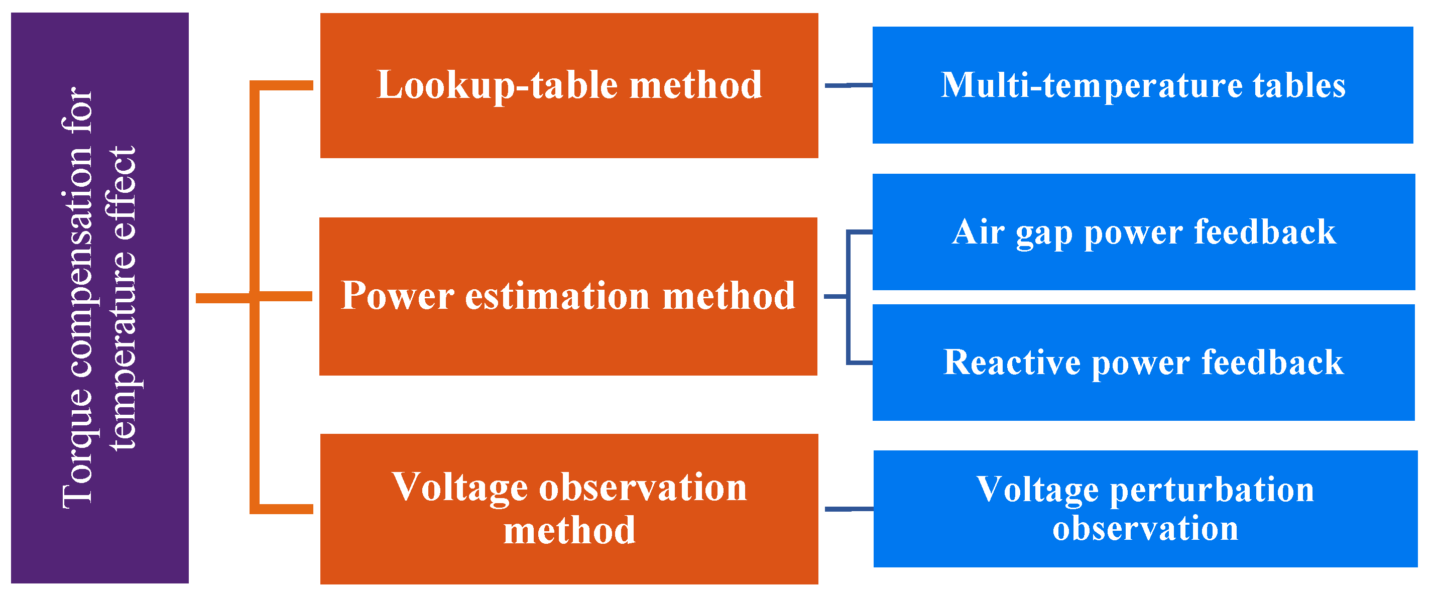
In addition, as shown in
Figure 1, it is resummarized according to literature [
25]. With the aim of studying the influence of permanent magnet temperature change on the electromagnetic torque, the multiple temperature table lookup method [
2,
4], power estimation [
26,
27] and voltage disturbance observation [
28] have been proposed. However, these research mainly focus on torque accuracy and do not include torque–current optimization after torque compensation.
In summary, due to the parameter saturation characteristics and temperature-sensitive characteristics of PMSM, it is difficult for most existing optimization mapping methods to consider both the optimization of machine efficiency in the whole operating range and the static torque following the performance under the change of permanent magnet flux. In this paper, a comprehensive torque–current optimization method based on offline optimization and online compensation is proposed. In offline optimization, a data-driven model and anti-degradation Nelder–Mead Simplex(NMS) optimization algorithm are used. In online optimization, the variation of permanent magnet flux is considered and a multi-temperature model is used to realize static torque compensation. The method can not only reduce the computational load of the microprocessor, but also effectively compensate for the deviation of the torque and the optimal current angle caused by the change of the motor parameters with the temperature.
2. Basic Principle of Current–Torque Mapping in Whole Operating Range
To simplify the analysis, the following assumptions are made for the permanent magnet synchronous motor: ① The saturation of the magnetic circuit, the hysteresis, the eddy current and the skin effect of the conductor are ignored, and the partial voltage of the stator resistance is not considered; ② The motor current is a symmetrical three-phase sinusoidal current, ignoring the higher harmonics of the magnetic field; ③ The influence of temperature on the parameters is not considered. The voltage equation and electromagnetic torque expressions of the salient pole permanent magnet synchronous motor in the d-q rotational coordinate system are shown in Equation (1) and (2).
where:
ud,
uq—d-q axis voltage;
id,
iq—d-q axis current;
Ld,
Lq—d-q axis inductance;
ψf—permanent magnet chain amplitude;
ωe—motor synchronous angular velocity;
Te—motor electromagnetic torque; and
p—motor pole pair numbers.
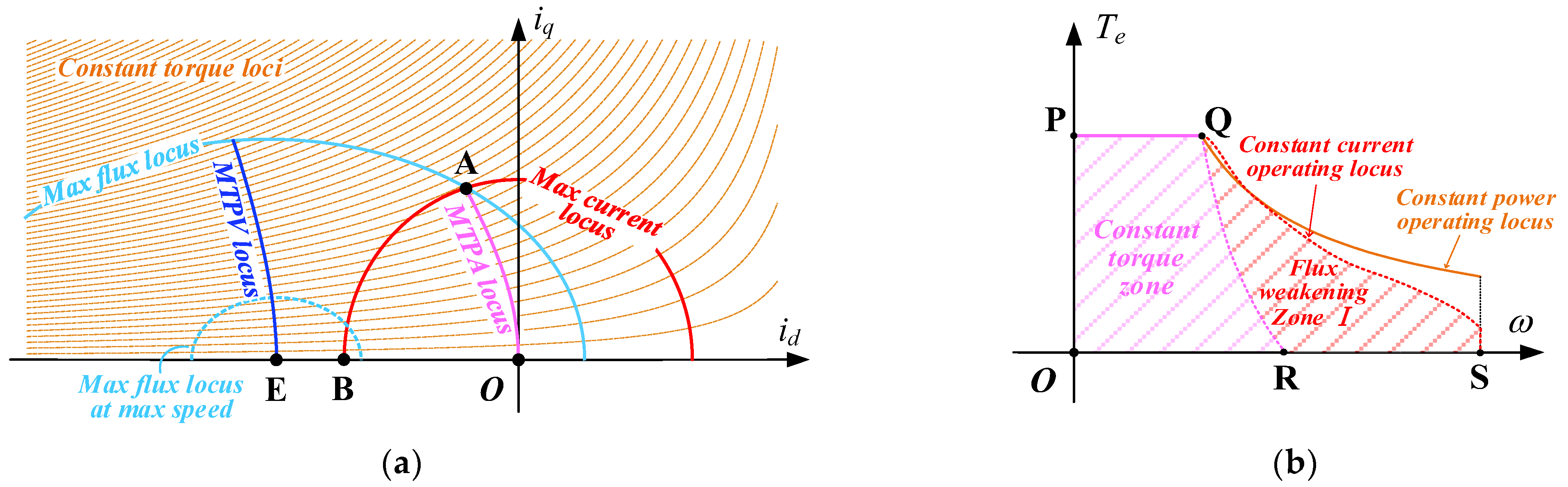
The goal of the current–torque mapping optimization is to maximize PMSM efficiency and torque capacity in the feasible range. Taking the electromotion mode of the PMSM drive system as an example, the optimal mapping of the whole operating range can be divided into two cases (
Figure 2 and
Figure 3) depending on whether the amplitude of the PMSM short-circuit current
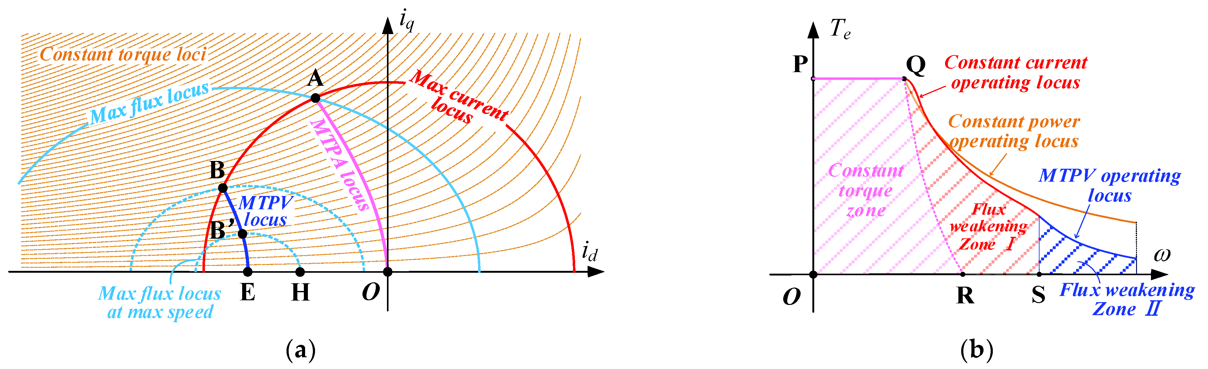
is within the maximum allowable current of the driver. Depending on whether the maximum voltage limit of the PMSM drive system is reached, the torque-speed operating zone is naturally divided into the constant-torque zone and flux-weakening zone. In
Figure 3b, the difference between flux-weakening zone I and II is whether the maximum torque point is mapped to the maximum current curve or the MTPV locus, respectively.
For the optimal efficiency problem, the unified expression with minimum copper loss as the optimization objective is shown in Equation (3). The constraint conditions of the voltage source inverter are shown in Equations (3b) and (3c). The maximum phase current amplitude of the motor driver is
ismax, and the bus voltage is
. Equation (3d) is the equality constraint of the electromagnetic torque realization, and
Tcmd is the target torque.
When the drive system is running in the constant torque zone, the current operating point in the OA section of the MTPA curve is not limited by the maximum current or voltage of the inverter. The torque–current optimization problem based on the MTPA strategy is composed of the objective function shown in Equation (3a) and the constraints shown in Equation (3d) [
29]. The Lagrange multiplier method is used to obtain the optimal current value, as shown in Equation (4).
When the motor speed increases and A on the MTPA curve is outsidethe range of maximum flux limitation, the voltage constraint condition of the current plane affects the external characteristics of the torque. The maximum torque point in the weak flux region in
Figure 2a may be on the maximum current circle, or, as shown in
Figure 3a, part of the weak flux region II may be on the MTPV curve. The difference between the two cases is whether the ideal short-circuit current operating point (
) of PMSM is outside or inside the current circle. The d-q current point optimization problem for maximizing the external characteristics of the torque is shown in Equations (5a)–(5c).
As shown in
Figure 3b, according to different key constraints, there are certain conditions in the optimization of the maximum output torque, such as optimal trajectory of constant maximum torque, maximum current and MTPV. The optimal current value on the MTPV curve is shown in Equations (6) and (7).
3. Non-Ideal Factors Affecting Optimal Current Distribution
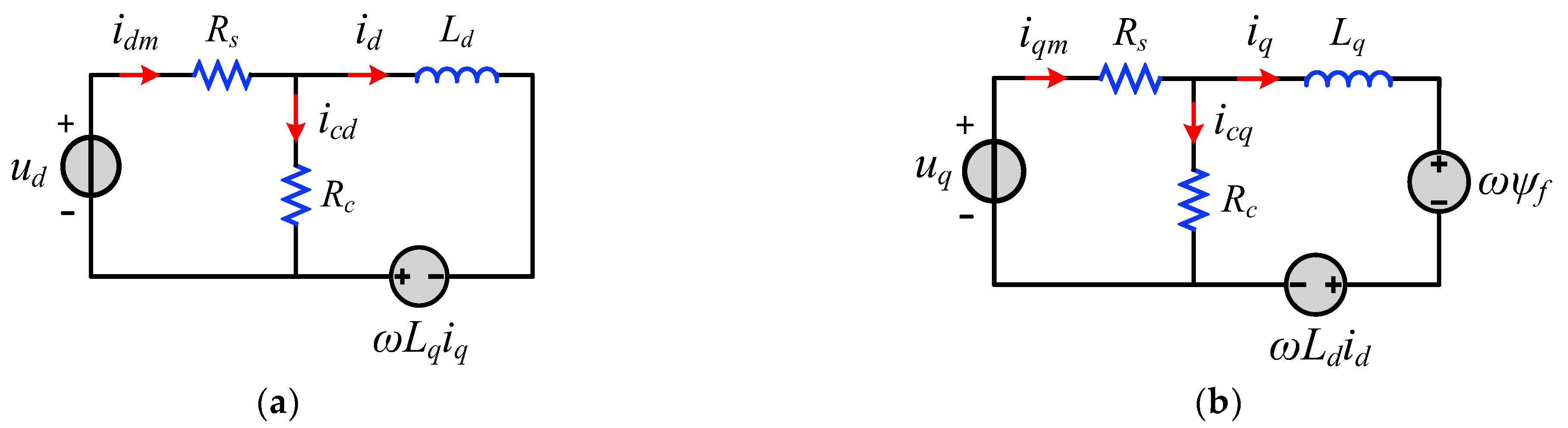
The neglected ferromagnetic loss of the simplified PMSM model in Equations (1) and (2) is usually represented by the model with an equivalent ferromagnetic loss resistance in
Figure 4. The PMSM voltage equation considering the stator ferromagnetic loss is obtained by ignoring the stator copper loss resistance
Rs as shown in Equations (8) and (9). Where,
Rc is the equivalent ferromagnetic loss resistance,
idm and
iqm are the equivalent dry circuit current at the motor port,
icd and
icq are the branch current on the equivalent ferromagnetic loss resistance, and
id and
iq are current values on the counter electromotive force branch.
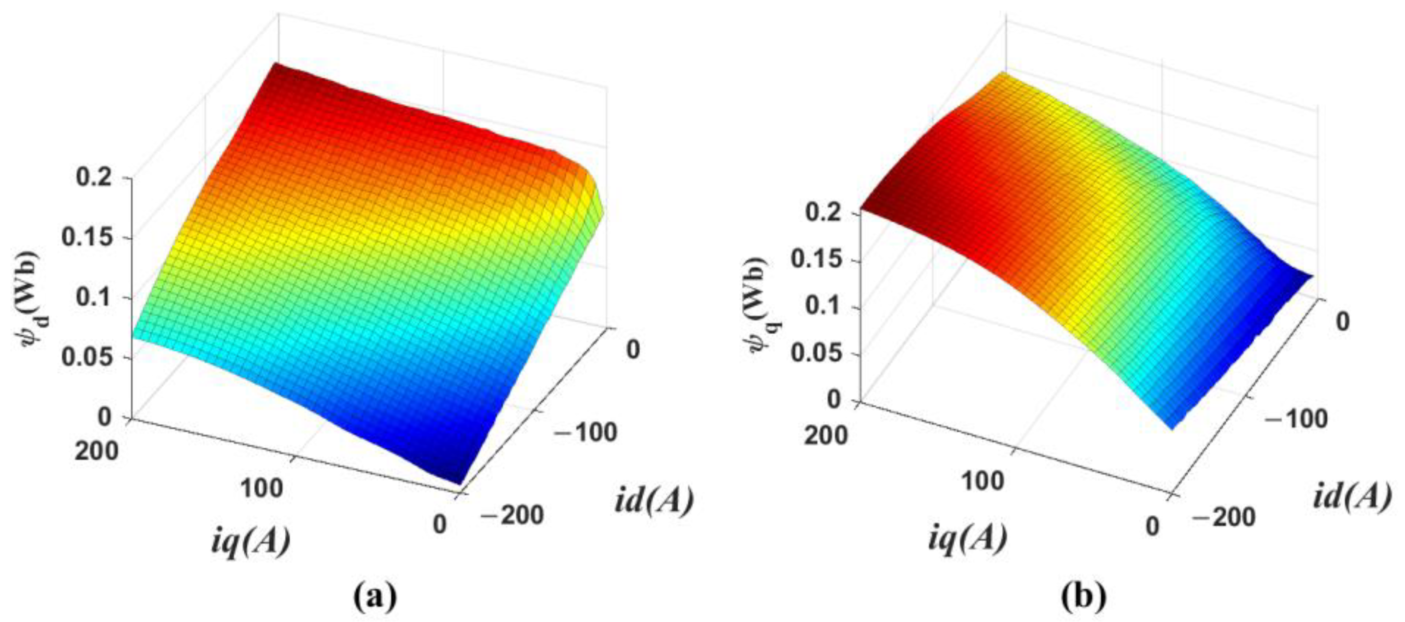
When the equivalent ferromagnetic loss resistance is considered, the complexity of electromagnetic torque becomes much higher, and the optimization results are related to the motor speed, so it is difficult to obtain precise optimization results as in Equations (4) and (6) by analytical methods. In addition, considering the magnetic circuit saturation of PMSM, it is more difficult to analyze the optimal current angle than the standard MTPA method. As shown in
Figure 5, it is the finite element simulation result of the parameters of the experimental prototype which change with the d-q axis current.
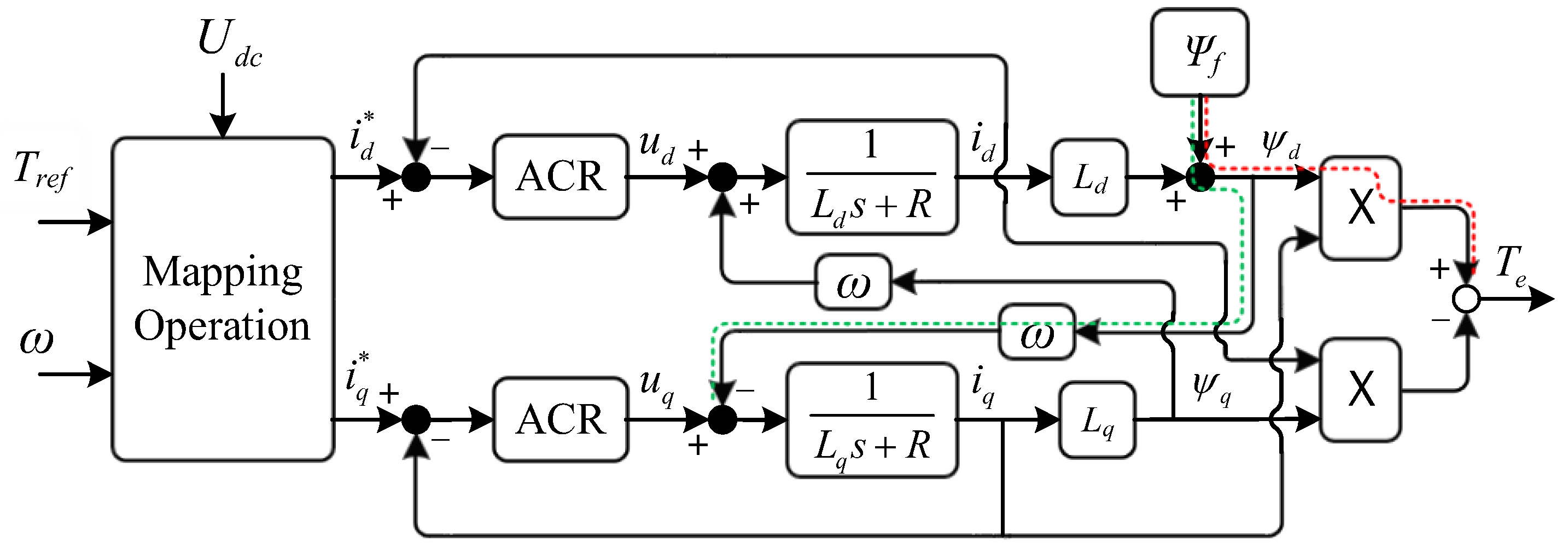
Moveover, the magnetic chain in the d-q coordinate system also changes in time with the temperature of the magnetic steel [
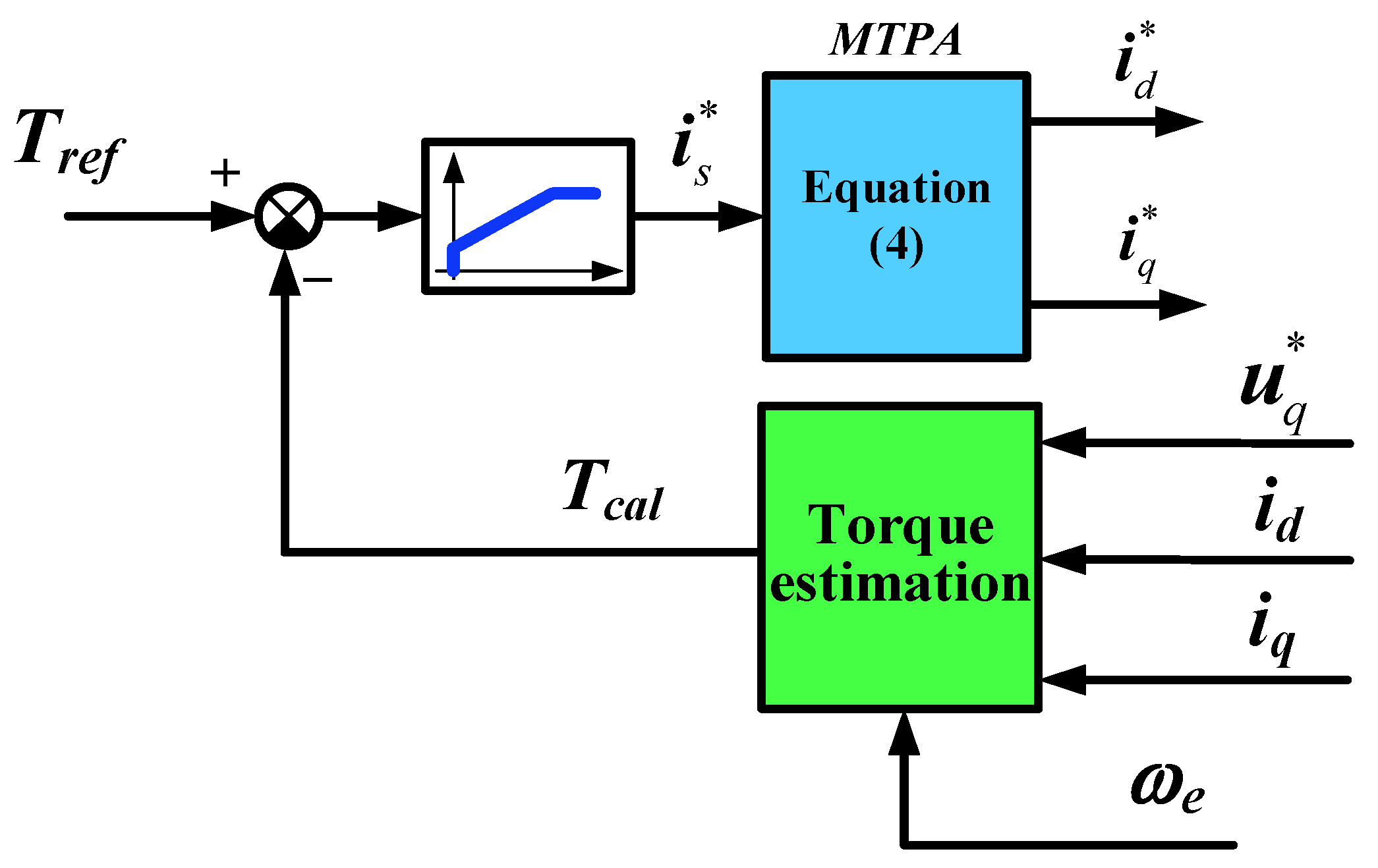
25]. The permanent magnet flux decreases with the increase of the rotor temperature. In the PMSM torque control system, as shown in
Figure 6, the decrease of the permanent magnet flux directly affects the permanent magnet flux through the path signed by the red dashed line and this change also reflects in the q axis voltage through the path signed by the green dashed line. Therefore, it is a very effective method to achieve torque compensation by observation of voltage or flux [
29].
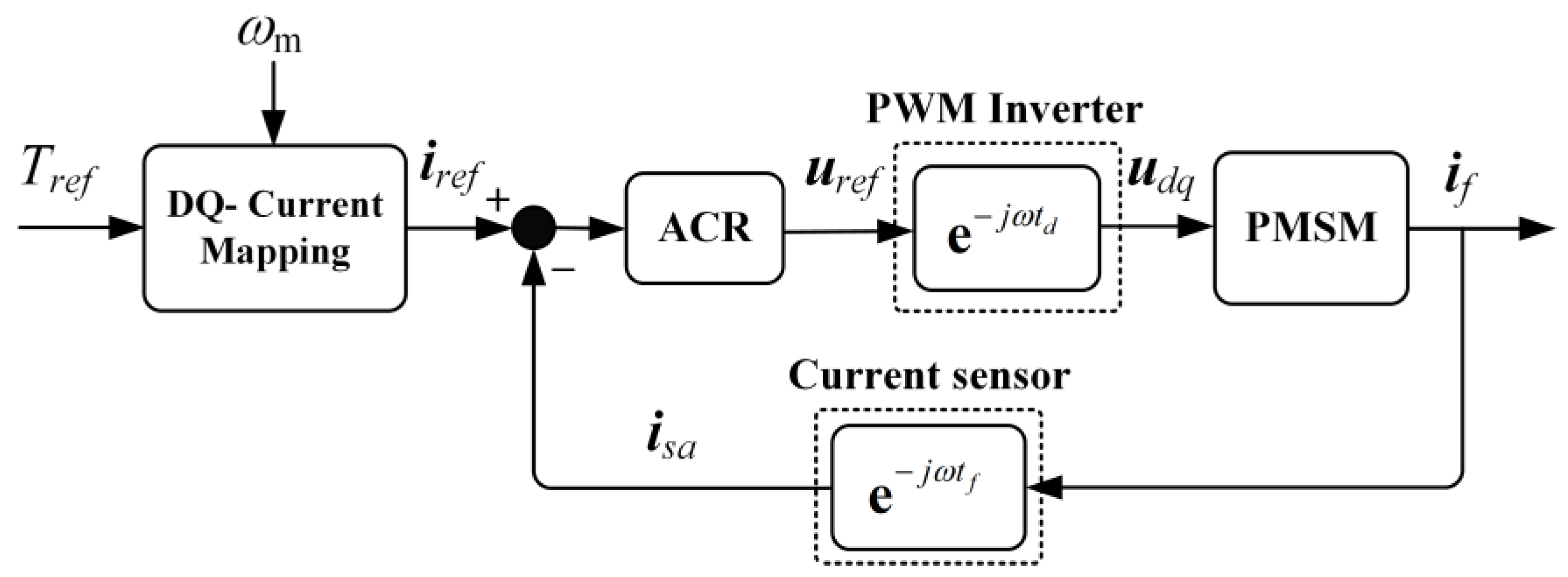
In summary, the analytical analysis of the efficient operation of PMSM is extremely complicated due to the parameter characteristics of saturation and variation with temperature. As shown in
Figure 7, in common PMSM control systems, there is usually a current sampling delay
tf and PWM wave delay
td. With the effect of closed-loop current control, the result current vector
isa equals tothe current instruction vector
iref, the relationship between the current and voltage vectors is shown in Equation (10).
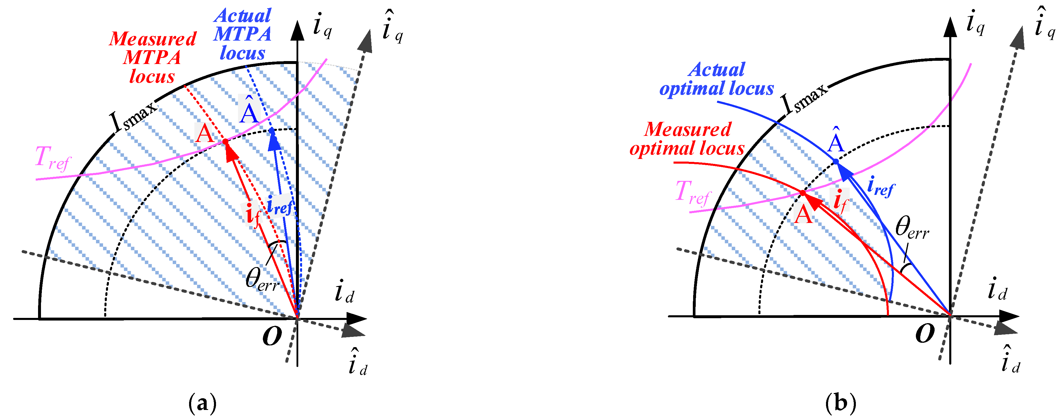
As shown in
Figure 8a, the current vector
isa moves from the position OA to OÂ in the constant torque region due to the current sampling delay, so that the desired optimal angle is partially moved to the first quadrant of the current plane. The situation of the flux-weakening region is shown in
Figure 8b. The angular deviation may cause the actual current operating point to be outside the flux limit curve, resulting in insufficient actual voltage margin and current loop instability. This also increases the complexity of the model.
A simple and easy to implement phase compensation method is shown in Equation (11) [
30], which directly compensates for the angular deviation of the sampling link by approximating the sampling channel as the phase-frequency response of the first-order inertial link.
4. Proposed Torque–Current Optimization Mapping Method
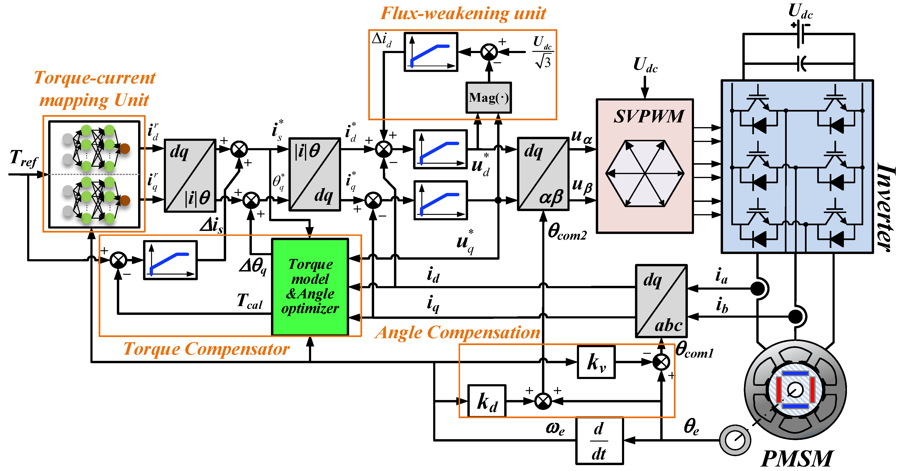
In order to deal with the highly complex model and optimization problems caused by motor saturation and time-varying parameters, a torque–current optimization method based on a data-driven model was proposed. As shown in
Figure 9, The torque–current mapping unit is a forward neural network (FNN) obtained by offline optimization data training, which ensures the optimal steady-state torque accuracy and copper loss of PMSM in the whole operating range at room temperature. The permanent magnet time-varying torque compensator synchronously compensates torque and current angle according to the multi-temperature offline model. The flux-weakening unit ensures that the current loop does not get out of control during the dynamic control process.
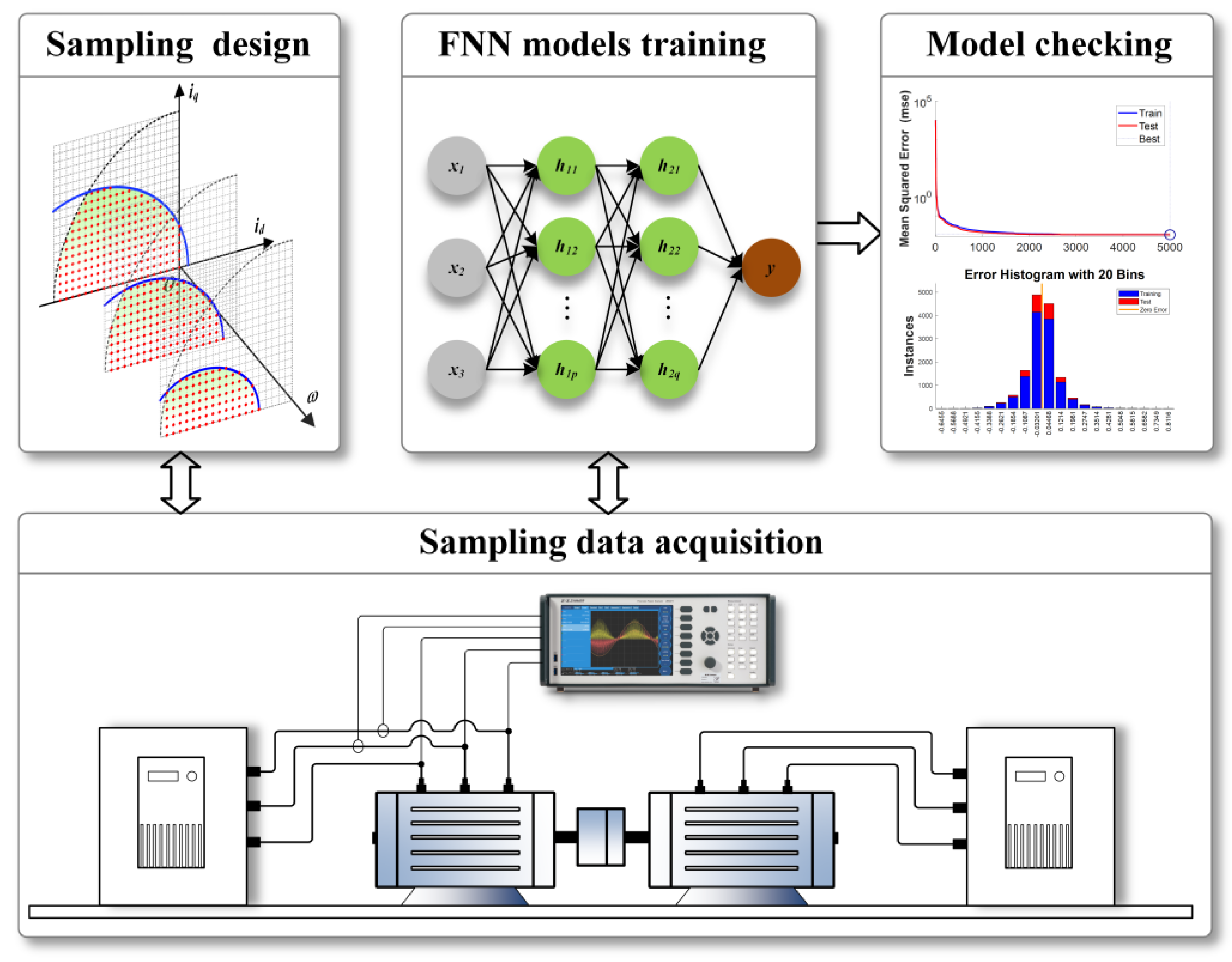
The overall block diagram of the offline optimization method based on the NMS method is shown in
Figure 10. First, the boundary limit flux of the steady-state current operating zone was explored by offline experiments at multiple speeds, and then the upper computer software was used to automatically obtain and record the limit flux boundary in the feasible current zone, avoiding the complicated and inefficient manual screening. The stationary test points constitute the sample space. Offline-trained FNN models are used for estimating torque and flux amplitude, and their inputs are the measured d-q axes current and speed.
The black-box optimization problem of specific construction is shown in Equation (12), where M is a sufficiently large positive number and
is the maximum allowable flux amplitude. Two offline models
and
provide constraint information about the torque and flux, respectively. However, since the black-box model, efficient optimization algorithms such as Newton’s method and conjugate gradient method cannot directly solve this type of problem. The solution goes back to the basic direct search method.
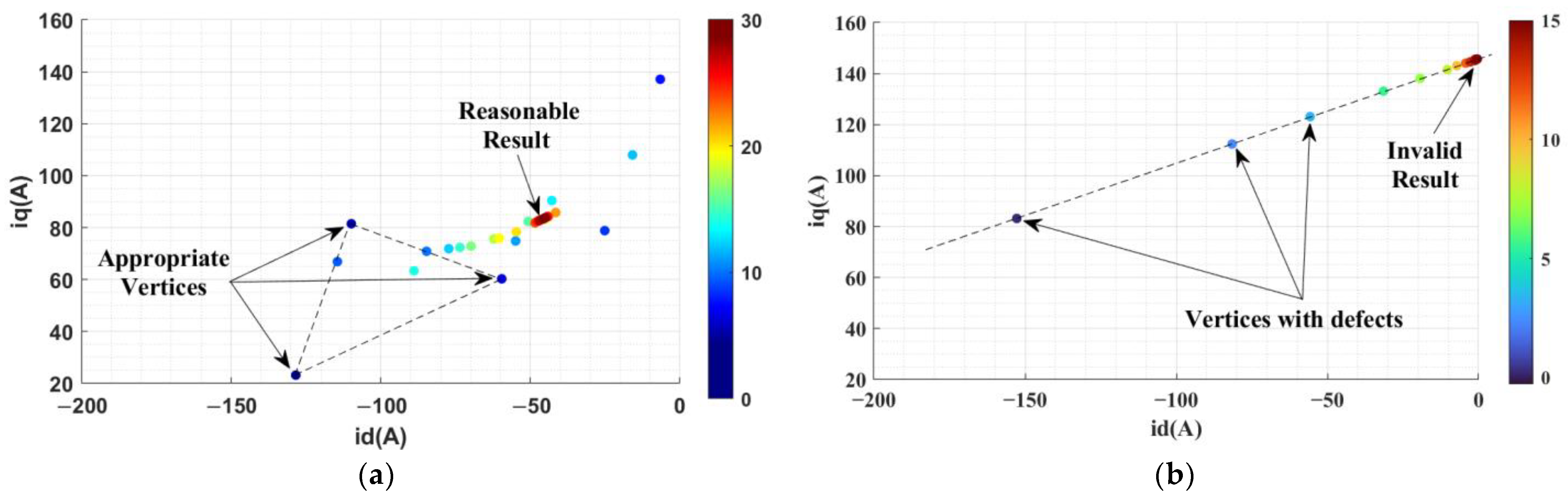
According to the requirements of the main drive motor torque control of electric vehicles, it is necessary to complete a multi-objective optimization for each target torque instruction in a limited time (usually no more than 2 ms) to obtain the target current instruction. In this paper, a direct search based on the NMS method is applied. The core idea is to use n + 1 initial points to form a polyhedron in an n-dimensional space, use the worst endpoint and the centroid of the remaining vertices to form a pseudo-gradient direction, and finally obtain a new endpoint to replace the worst vertex through a one-dimensional search. The idea is simple and easy to implement. The main problem of the traditional NMS method is that there is no constraint on the polyhedron vertices in the optimization process. As shown in
Figure 11, when the linearity between vertices reaches a certain degree, the directional search capability is lost and fail to convergence to the global optimum.
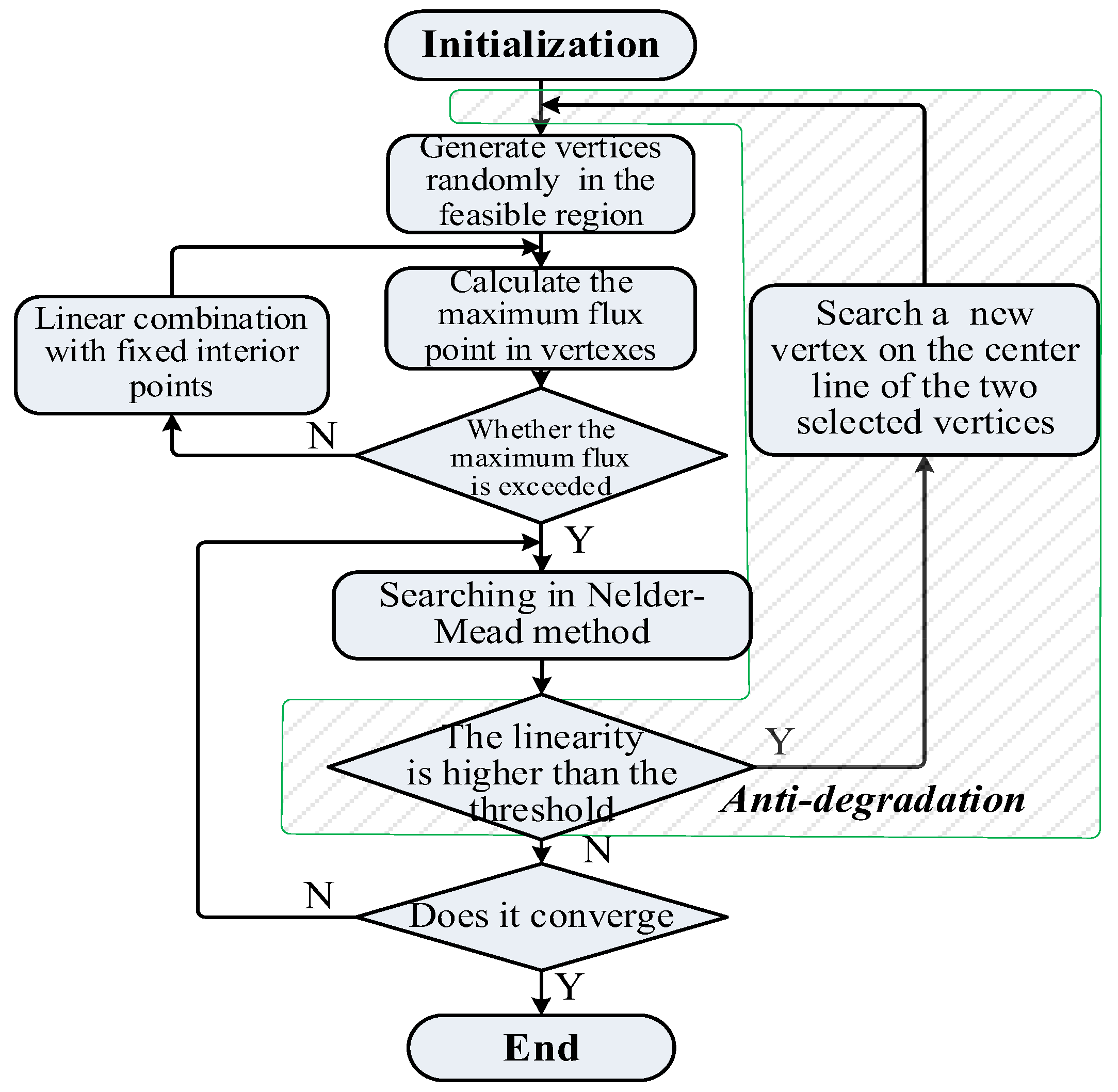
To solve the vertex degradation problem of the NMS method, an improved method is proposed, the specific procedure of which is shown in
Figure 12. The linearity between three points is used to determine if the vertex is degraded. Once degraded, the worst vertex is discarded and replaced by a new feasible point which is searched on the centerline of the other vertices.
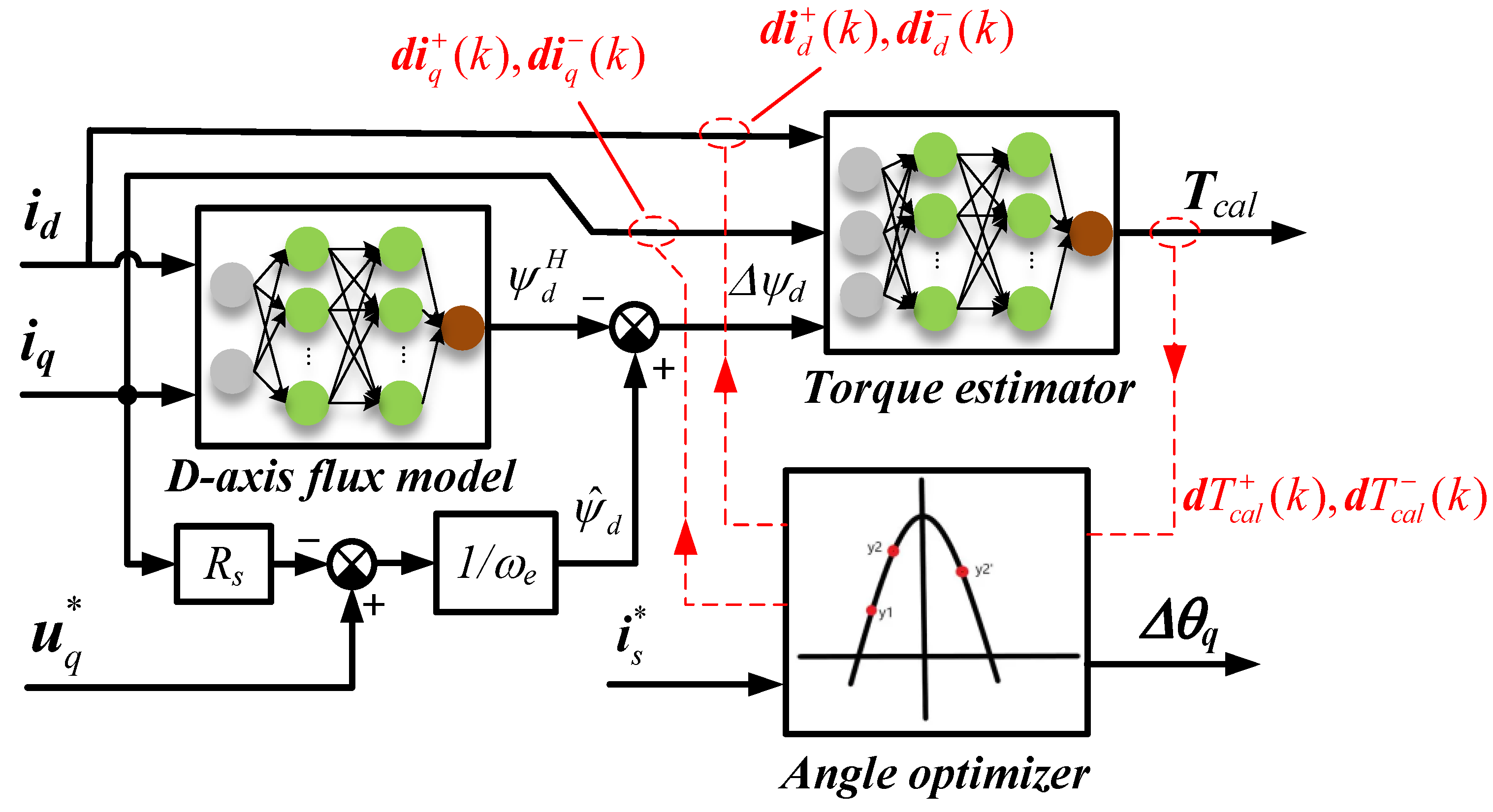
Torque estimation and angle optimization units are shown in
Figure 13. The optimal method for the current angle uses an online estimate d d-axis flux
, then minus its output to the highest ambient temperature for d-axis flux
, to obtain the temperature caused by d-axis flux deviation
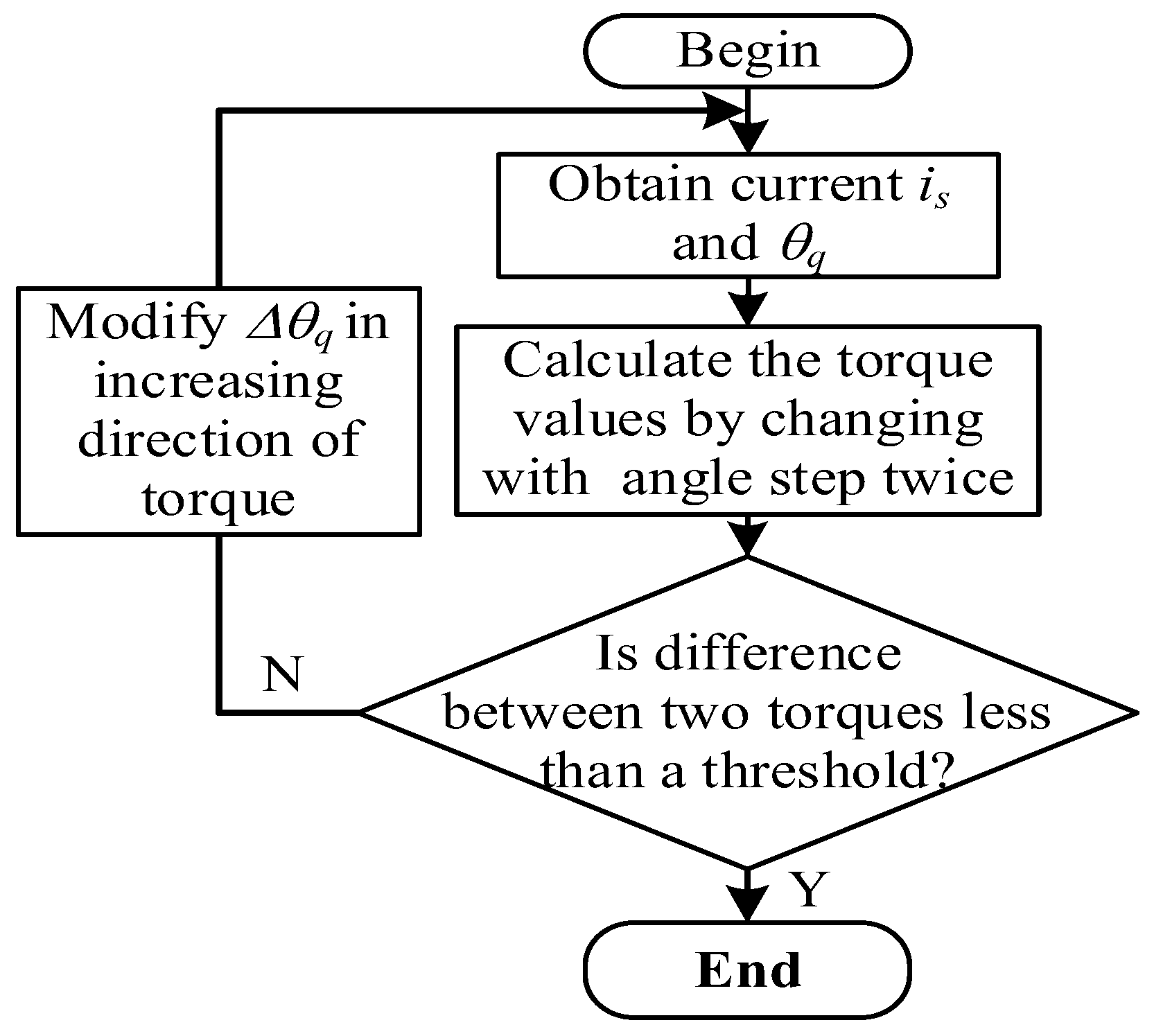
. The torque estimator with a wide temperature range can be obtained by using the flux deviation and d-q axis current offline experiments at different temperatures. When the searching unit works for optimal current angle, a torque model is used to calculate the two torque estimates that increase/decrease the current angle of the current vector in the same step, and the relationship between the two is compared to determine whether the applied current angle is optimal. The procedure is shown in
Figure 14. The obtained d-axis flux error
includes the temperature-induced torque error, and achieves that the flux input to the torque estimator is independent of the optimal current angle, and the online optimization is simplified significantly. In addition, the actual motor temperature changes very slowly, so the iteration frequency of the torque compensation unit is very low, which does not require the excessive computational effort.
5. Experimental Verification
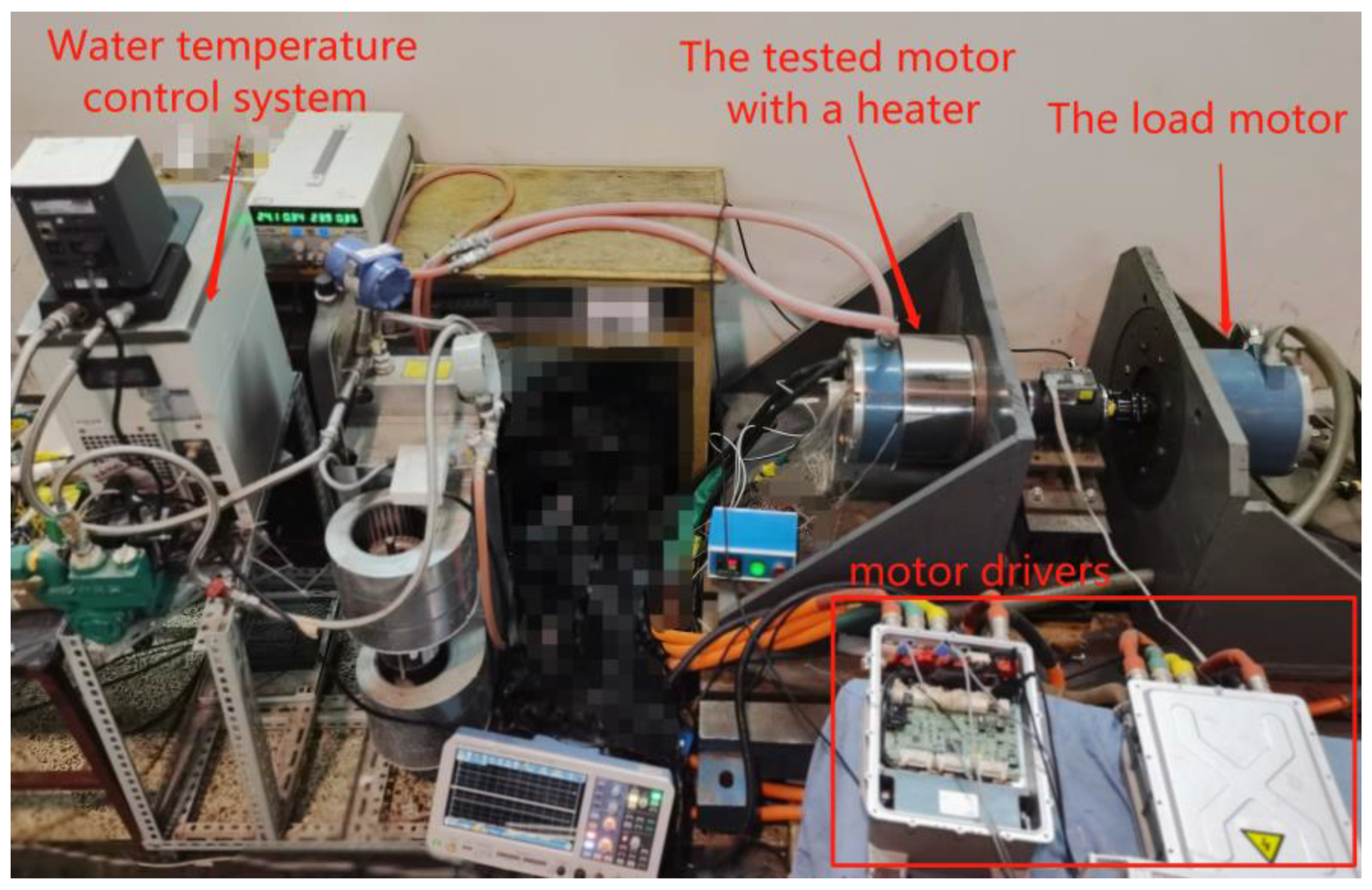
To verify the torque-following accuracy of the proposed scheme, the torque and current angle compensation performance of the method with temperature changes is analyzed. The analysis was performed on a 10kW PMSM test bench. The field experimental environment is shown in
Figure 15. The basic parameters of the prototype are shown in
Table 2. The accuracy of the torque sensor is ±0.5N·m.
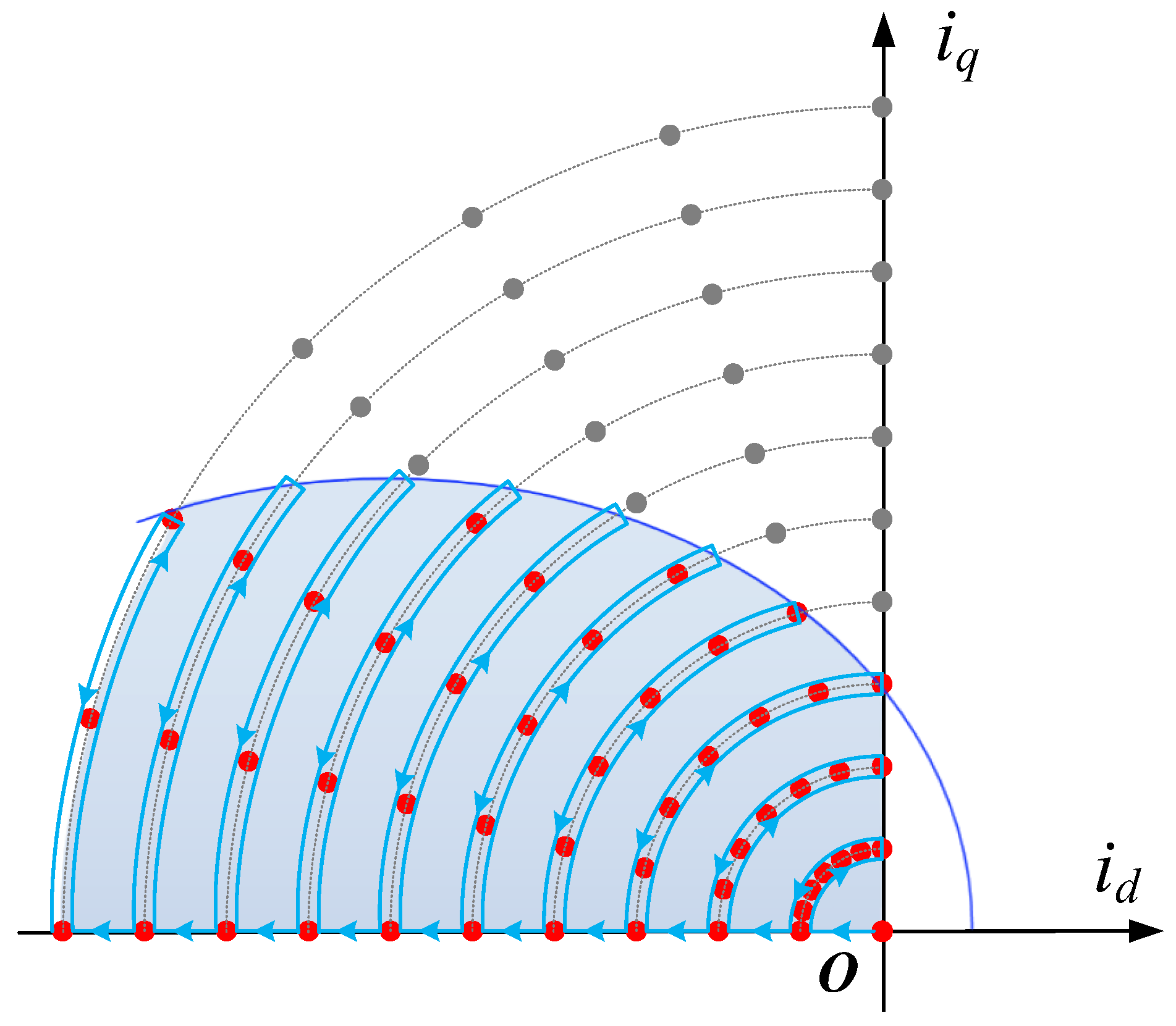
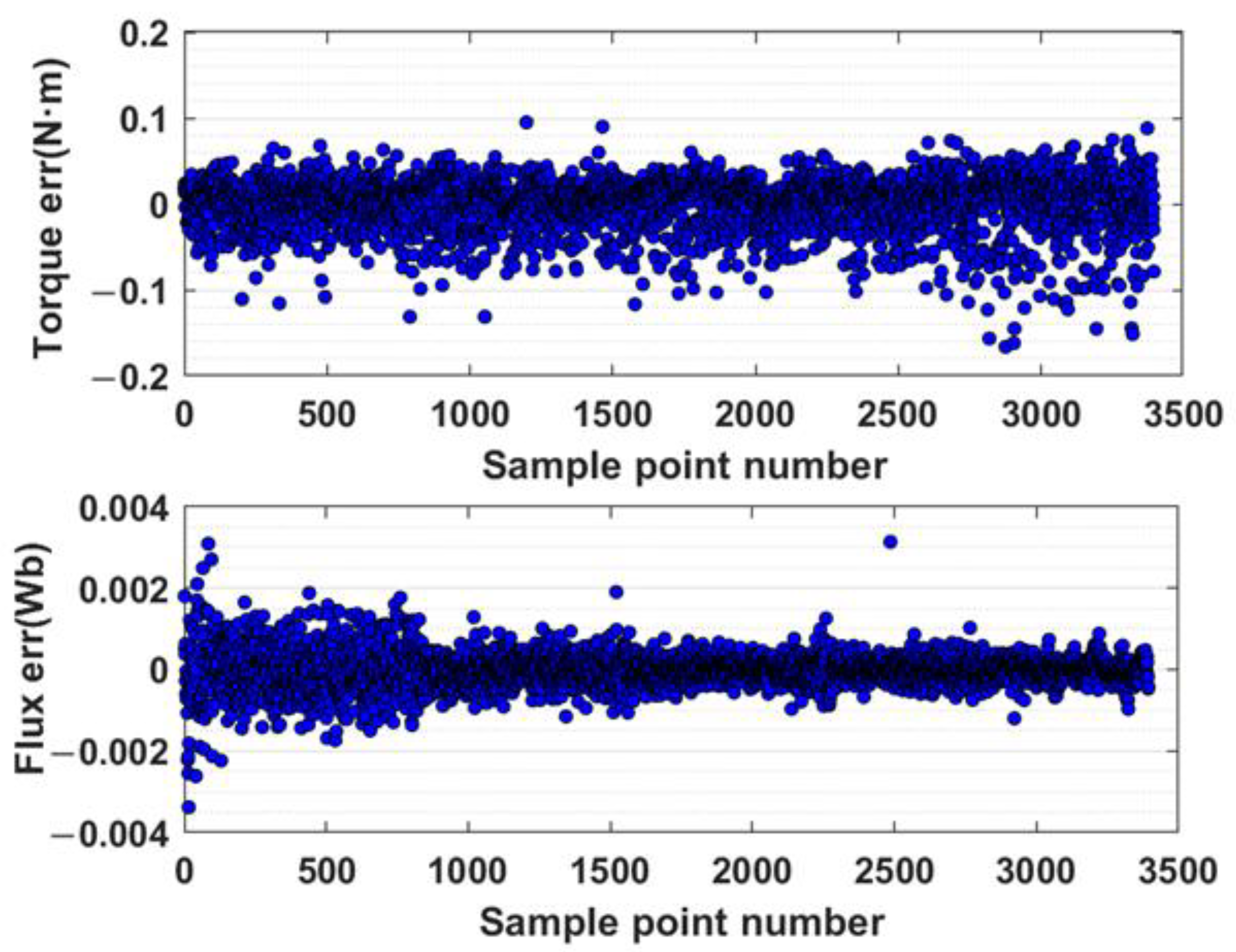
In the offline model acquisition stage shown in
Figure 10, stationary current operating points at several speeds at room temperature were first obtained as samples for building the FNN model of torque, current, and flux. The trajectory of the current points during the experiment is shown in
Figure 16, and the error results of the torque model and flux linkage are shown in
Figure 17. The maximum designed torque of the measured motor is 120 N·m, indicating that the modeling errors of the torque and flux are about 0.1% and 3%.
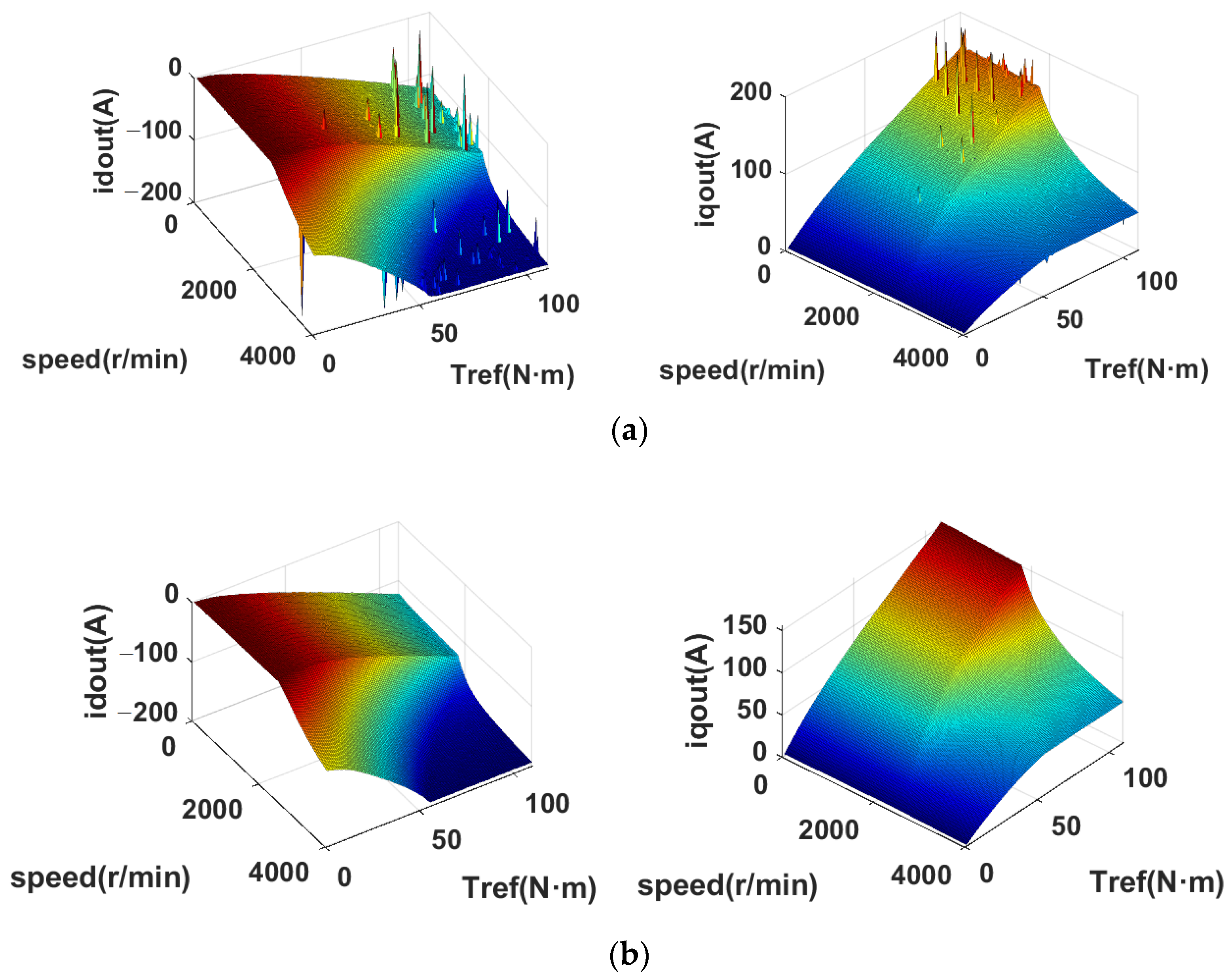
The cost function was constructed according to Formula (12), and the improved NMS method as shown in
Figure 12 was used to obtain the current mapping results of each operating point in the external characteristic area of the motor. The improved NMS method is compared with the basic method, and the results are shown in
Figure 18, indicating that the risk of optimization failure is greatly reduced after the improvement.
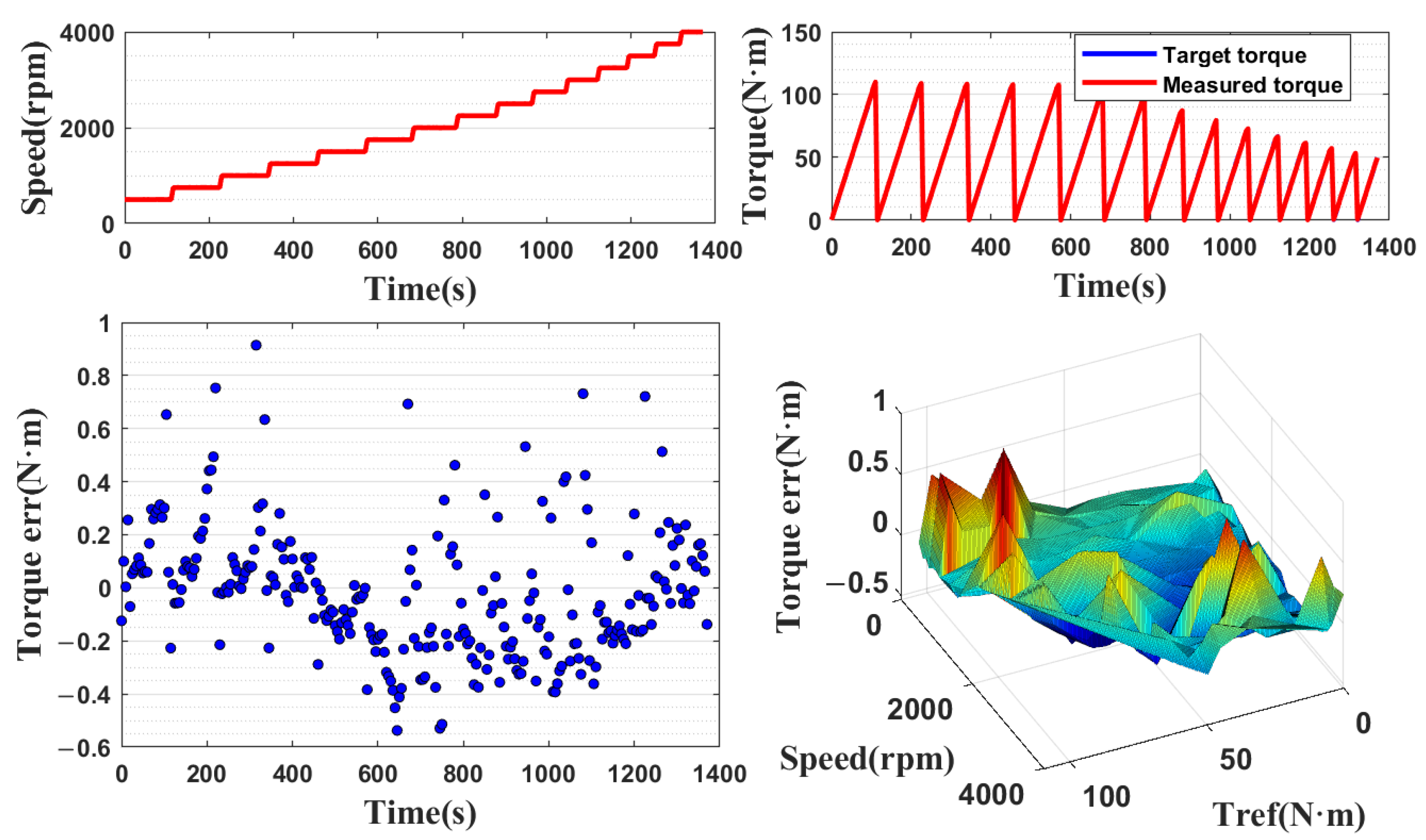
The offline optimization results are used to train the torque–current mapping unit throughout the whole operating range. When the motor temperature is room temperature, the static torque accuracy verification experiment of the open-loop control system is is performed separately. The experimental results are shown in
Figure 19. The actual relative error of control using the torque mapping unit alone is within 1% at room temperature.
To obtain the wide temperature torque model shown in
Figure 13, the motor was stabilized at five different temperature values of 2000rpm by a heater, and the operating data for several temperature were obtained by the same experimental method as shown in
Figure 16. The error of trained torque model for a wide temperature is shown in
Figure 20.
In order to independently verify the optimization accuracy of the torque compensator, the torque–current mapping unit in
Figure 9 was first removed. As shown in
Figure 21, the angle optimization unit in
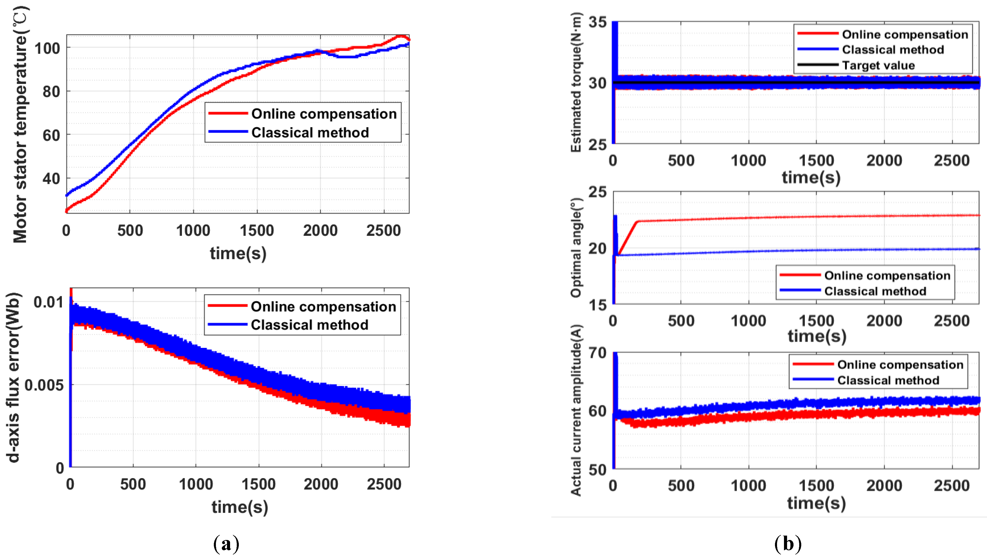
Figure 15 is replaced with the formula MTPA method based on nominal parameters. Under the condition that the motor runs stably at 2000rpm and the torque command is 30N·m, the measured motor is heated by a heating device, and the experimental results before and after replacement are compared.
The experimental results in
Figure 22a show that the d-axis flux of the two groups gradually decreases by about 7% as the stator temperature increases. As shown in
Figure 22b, the current amplitude of the online optimization strategy is smaller, i.e., the copper loss is lower, while the torque follows the specified value. The difference of current amplitude between the two strategies is about 2.2 A, and the difference in copper loss is about 6%.
6. Conclusions
Since the existing torque–current mapping method cannot consider the influence of time-varying permanent magnet flux and parameter saturation simultaneously, this paper conducts an exploratory research on the solution using a black-box model for offline optimization in combination with online optimization. The main conclusions are as follows:
(1) For the offline optimization problem of the black-box model, the traditional NMS method has the fatal flaw of vertex degradation. The anti-degradation strategy proposed in this paper significantly reduces the probability of algorithm failure, under the condition that the computation quantity is slightly increased.
(2) The experiment comfirms that the offline optimization strategy has a better steady-state accuracy performance in the whole operating range. With the change of motor temperature, the proposed online torque compensation strategy can accurately compensate the torque deviation by changing d-axis flux and synchronously modifying the optimal current angle.
In the proposed method, the acquisition of multi-temperature experimental data inevitably increases the experimental cost, and it still needs to be explored how to achieve a reasonable compensation effect by using the fewest experiments. When the computational power of embedded processors is gradually increaed, one direction of this research is to develop a high-performance torque observer through the torque model and online voltage deviation compensation, and to use similar literature [
23,
24] and the method of online calculation, which has the potential to realize online optimization in real-time.


