1. Introduction
In recent years, the rapid development of wireless energy transmission technology and its gradual application in various electrical devices have greatly contributed to improving the charging modes of electrical devices. While wireless power technology has made significant contributions to the way electrical equipment is charged, it also faces the challenges of coupling and high power [
1]. As typical WPT applications, AUVs are increasingly used in ocean research and seabed exploration for science and industry [
2]. Despite significant advances in underwater robotics, their range, speed, scope, and payload are still limited by the type and capacity of on-board energy storage devices [
3]. Therefore, charging infrastructure is certainly important for underwater robots.
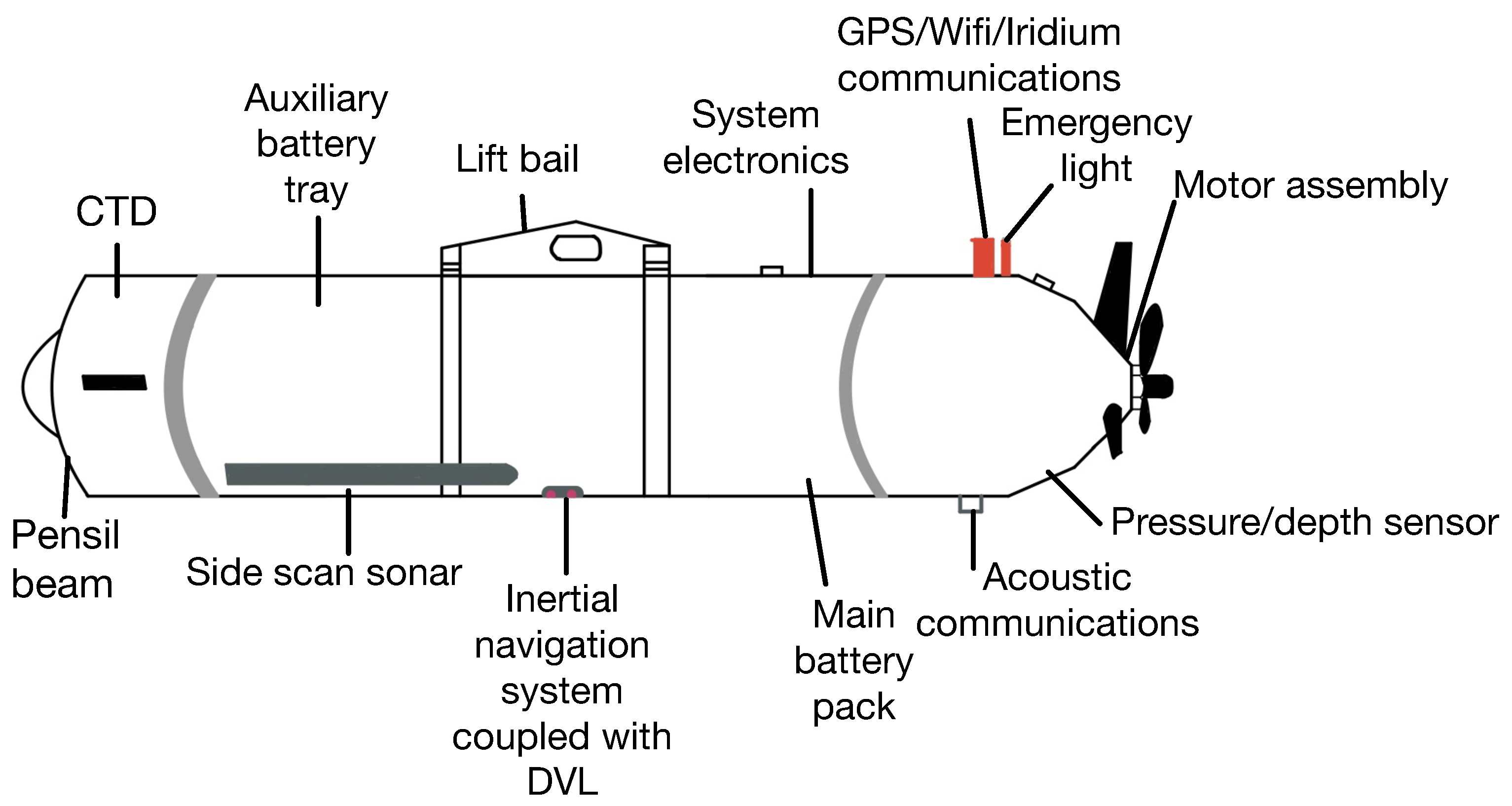
AUVs play an important role as a maritime force for exploring landscapes, salvaging shipwrecks, laying underwater cables, collecting underwater information [
4,
5], and protecting the privacy of ocean locations [
6], with the advantages of autonomous control and increased flexibility and freedom in maritime operations [
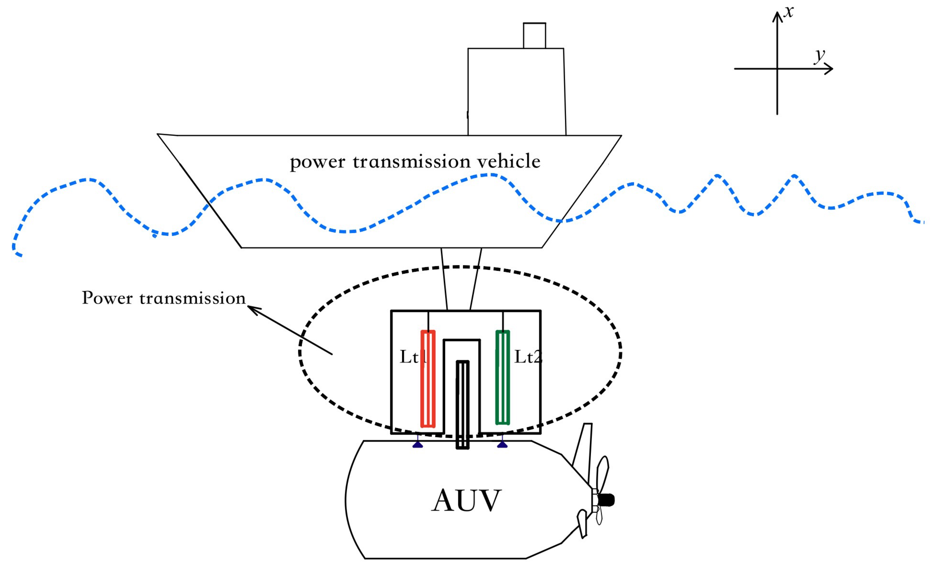
7], As shown in the example of the underwater robot in the
Figure 1. With the development of collision-avoidance navigation systems [
8] and AUV path tracking control [
9], the operation radius of AUVs has raised higher requirements. Successful underwater charging can increase underwater operation time and improve work efficiency. However, this process also faces problems such as corrosion caused by water intake and a cumbersome underwater charging process [
10]. A noncontact charging system transmits electrical energy in a contactless way through electromagnetic coupling between coils. The two sides of the circuit package alone, can play an isolation role. No contact reduces the risk of friction. These advantages make it an ideal charging method for AUVs.
The power transmission of AUVs [
11] mostly adopts a high-power limited charging system. However, there are problems with underwater wireless power supply systems. First, the transmitting power and the efficiency are not enough to drive an underwater robot. Second, when the distance between the two coils increases, the coil radius needs to increase. Finally, the power transmission is unstable because of the complex environment. Various solutions have been proposed for the stability of wireless charging [
12]. The docking system developed by the Woods Hole Oceanographic Institution in Woods Hole, Massachusetts, USA, uses a deep-sea mooring supported by a surface buoy for an Odyssey class underwater robot [
13]. The docking structure, electrical system, batteries, and data cables are supported by the mooring equipment. The underwater robot clamped by the slide frame is guided by a V-shaped latch before the power transfer starts. The docking station structure implemented in the REMUS Docking Station is popular among many researchers [
14]. It allows the creation of a protected garage near the underwater robot. The hardware of the underwater robot does not have to be modified. Marine Bird is an experimental AUV for underwater docking based on the concept named Base Landing [
15]. As the AUV approaches the base, the AUV is locked by hooks. Then, the lock connector is put down to complete the docking process. The battery of the underwater vehicle is charged by induction coupling. However, the system is heavy and expensive because of the use of motors.
An underwater glider can be recharged by another AUV [
16]. It was developed by researchers at Michigan Technological University, Michigan, USA, by Roughie. The glider wings act as guides, allowing the two vehicles to lean together. After a successful capture, the glider uses switchable magnets to strengthen the coupling before the power transfer begins. In addition, additional mechanical structures are needed to stabilize the core gap. However, this makes the structure of the system more complex.
Current research on wireless energy transmission technology has mainly focused on implementation, mainly through the electromagnetic induction type [
17], magnetically coupled resonance type, and ultrasonics type, among which magnetically coupled resonance WPT technology, which can achieve medium-range power transmission, is favored by many scholars [
18]. The magnetically coupled resonance WPT technology can achieve medium-range power transmission. However, in the complex environment of practical applications, this can lead to lateral or longitudinal displacement of the coil between the transmitter and the receiver, which diminishes output power and efficiency. This is the greatest difficulty to be addressed in wireless power transfer technology [
19]. By introducing the concept of parity-time (PT) symmetry in quantum physics, some scholars have solved the above problem of the WPT technique with good results [
20]. The total gain rate of the transmitter circuit is equal to the total loss rate of the receiver circuit, and the intrinsic resonant frequency of the transmitting circuit and the intrinsic resonant frequency of the receiving circuit are the same in the PT symmetry condition of a system. When the WPT is in the point symmetry region, the efficiency and output power of the system are independent of the coupling coefficient.
In Ref. [
21] was proposed a PT symmetry WPT system with a velocity compensation structure. An ordinary PT symmetric WPT system requires the same topology between the transmitter and the receiver, but this PT symmetric WPT system with a velocity compensation structure is asymmetric. However, the hamiltonian quantity (visible measurements from quantum mechanics) of the system is constant. Thus, it can be considered as PT symmetric. The condition for implementing the PT symmetry-based WPT system is that the transmitter and receiver circuits have the same topology and inherent resonant frequency. However, the change in operating frequency due to the change in transmission distance is only one of the characteristics of PT symmetry-based WPT systems. The above PT symmetry-based WPT system is highly robust in the PT symmetry region. However, when the system operates in the PT broken region, the change in the coupling coefficient of the system leads to a large change in the output power and efficiency of the system. It is difficult to achieve the efficient and fast transmission of electrical energy for wireless power transfer underwater. Therefore, ensuring operation in the PT symmetry range is the motivation for the work in this paper.
At present, most scholars have conducted experimental validation in the laboratory state. Li et al. [
22] investigated the influence of high pressure and axial misalignment on the electromagnetic coupler operation in the deep-sea environment. A 400-W prototype inductive coupler was constructed using a pot core. Wang et al. [
23] designed a wireless loosely coupled system for a man-pack AUV of the 50-kg class using a PM-core magnetic coupler. The designed coupler transfers 500 W of power at an efficiency of 88% when the gap distance varies from 6 to 10 mm. To adjust an electromagnetic coupler to AUVs structure, a new arc core structure is proposed in [
24]. The arc electromagnetic coupler is a modified EE core with the primary and the secondary housed on the base station and the AUV. The electromagnetic coupler made of Mn–Zn ferrite material was integrated into the shell structure of AUV made of plexiglass. The designed prototype has achieved an efficiency of 82% at the 5-mm gap for an operating frequency of 100 kHz.
The DTC-WPT system proposed in this paper has three advantages: firstly, it can resist the reduction of inductance and coupling coefficient caused by bias, and this design is less prone to misalignment than the design with flat end, which keeps the power transmission better in the strong coupling region; secondly, they are more robust and practical structures that can resist the effect of water flow while reducing eddy current losses. Finally, the circuit topology of the dual transmitter coils allows for twice the power transfer at the same input voltage level. In this paper, 39 W of transmitted power was achieved at an input voltage of 18 V, with an efficiency of 91.5%.
The main contribution of this paper is to model and analyze the DTC-WPT system based on PT symmetry. The magnetic field of a single transmitting coil magnetic coupler and the magnetic field of a dual transmitting coil magnetic coupler are compared in
Section 2. The electrical characteristics of a dual transmitting coil (DTC) WPT system are analyzed in
Section 3. A detailed description of the proposed DTC WPT system structure is given in
Section 4. In addition, an experimental verification is provided in
Section 5. It describes the power distribution between loads for different coupling cases. Finally, conclusions are offered in
Section 5.
2. Analysis of the Proposed Magnetic Coupler Structure
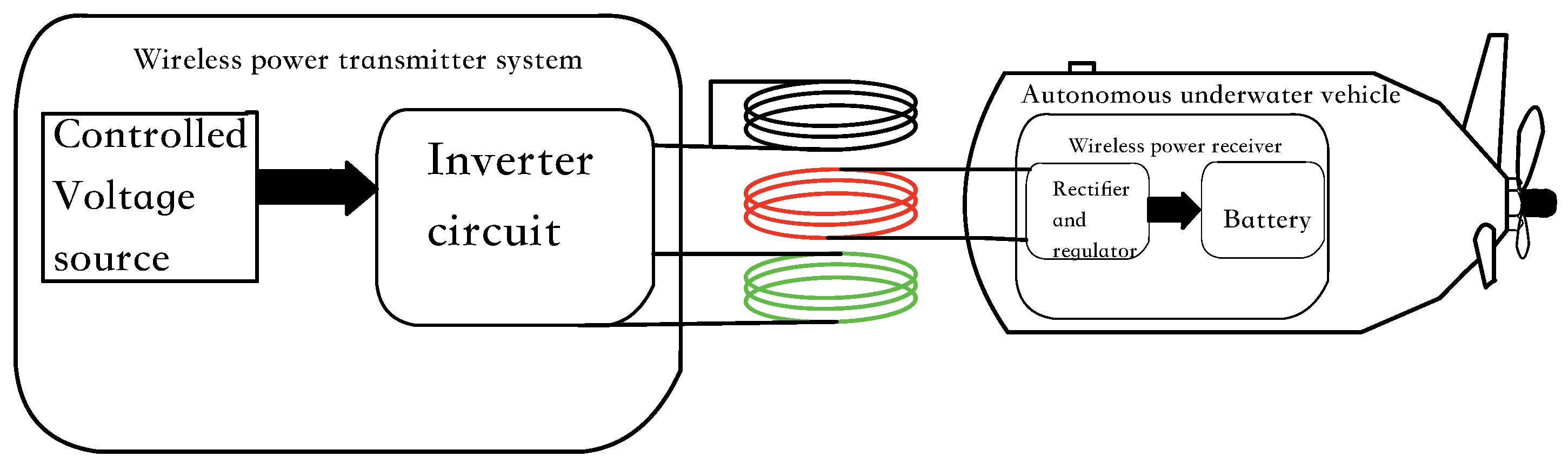
The schematic diagram of the proposed system in this paper is shown in
Figure 2.
Typically, single-coil coupling is mostly used in WPT systems to transfer energy. A single coil produces a magnetic field that diverges from the center of the coil. However, a pair of single pole coils with the same current direction will directly create a uniform magnetic field along one axis.
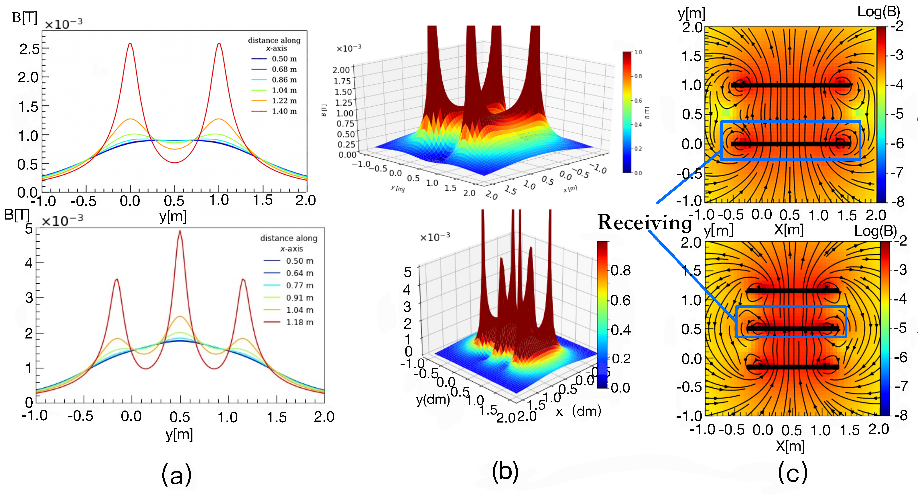
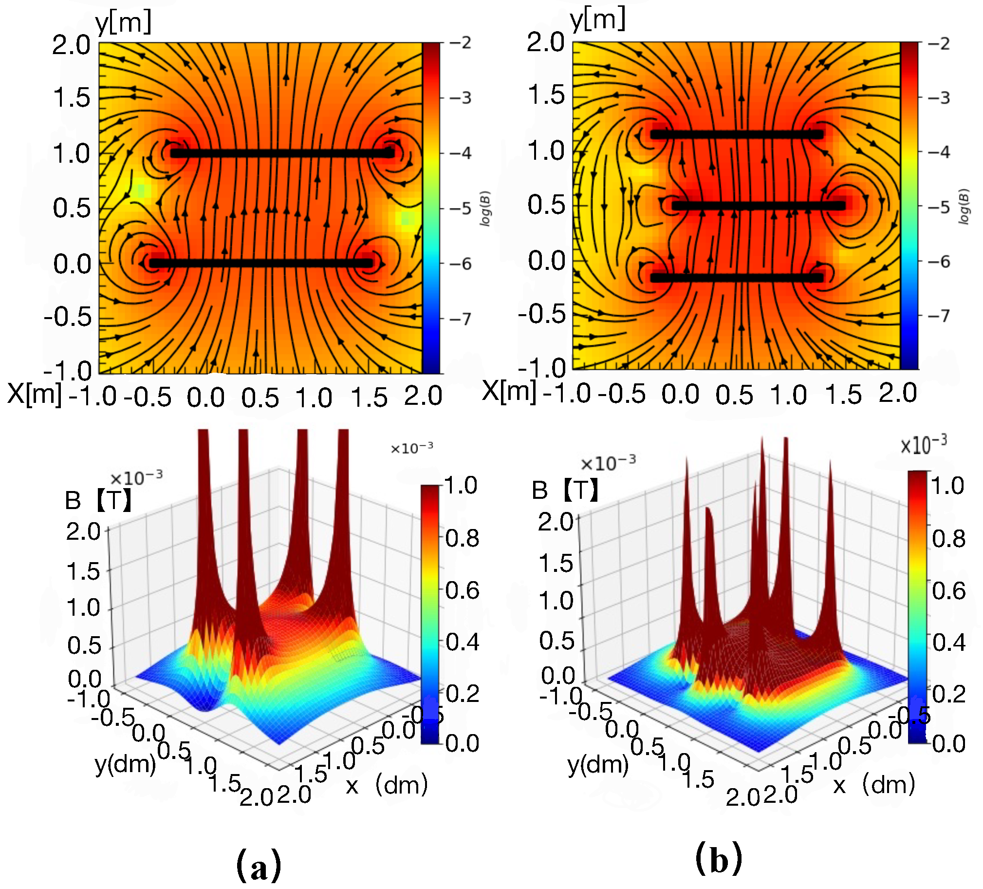
Figure 3a,b compare the magnetic field strengths of DTCWPT and conventional WPT on the receiving side, and in
Figure 3c it can be observed that the magnetic induction lines passing through the receiving coil in DTCWPT are more uniform and dense.
To realize a WPT system with higher efficiency and stronger robustness, a new WPT structure is proposed. It places the receiving coil in a double transmitting coil. The receiving coil is placed in a strongly coupled region with uniform and concentrated magnetic induction lines, effectively improving the robustness of the PT symmetric WPT [
25]. The magnetic fields generated by the Helmholtz and Maxwell coils at various points in space are investigated using a hybrid approach combining superposition principles and analytical results. The magnetic fields of the three Maxwell coils at various points in space are simulated and analyzed by evaluating the magnetic fields at any point in the coil arrangement space. This is based on iterating the magnetic fields generated by a finite number of current carrying wires several time without using advanced calculus, resulting in the simulation results shown in
Figure 3. It can be observed that the total magnetic flux B is superimposed on the two magnetic fields at the middle coil position. The magnetic induction lines are very dense at the middle receiving coil position. They are perpendicular to the coil.
The negative resistance part of the system is implemented by a feedback system and a full bridge inverter, the details of which are described in
Section 3. Two hypotheses are proposed based on the above analysis. In addition, separate parametric mathematical models describing circuit theory are developed.
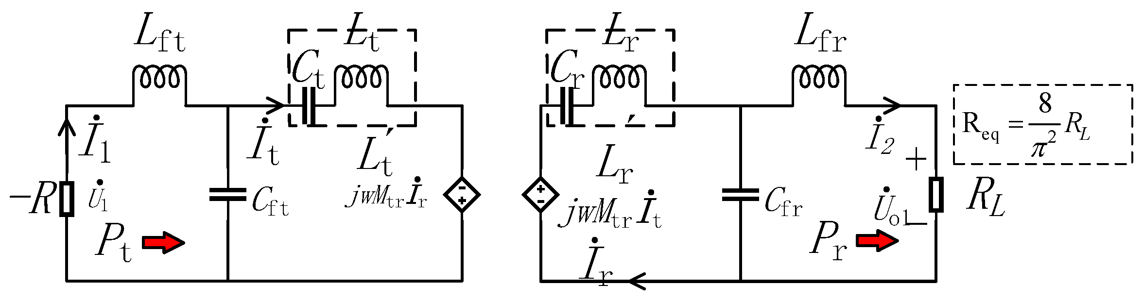
2.1. Case1 Single-Transmission Loop Wireless Energy Transmission
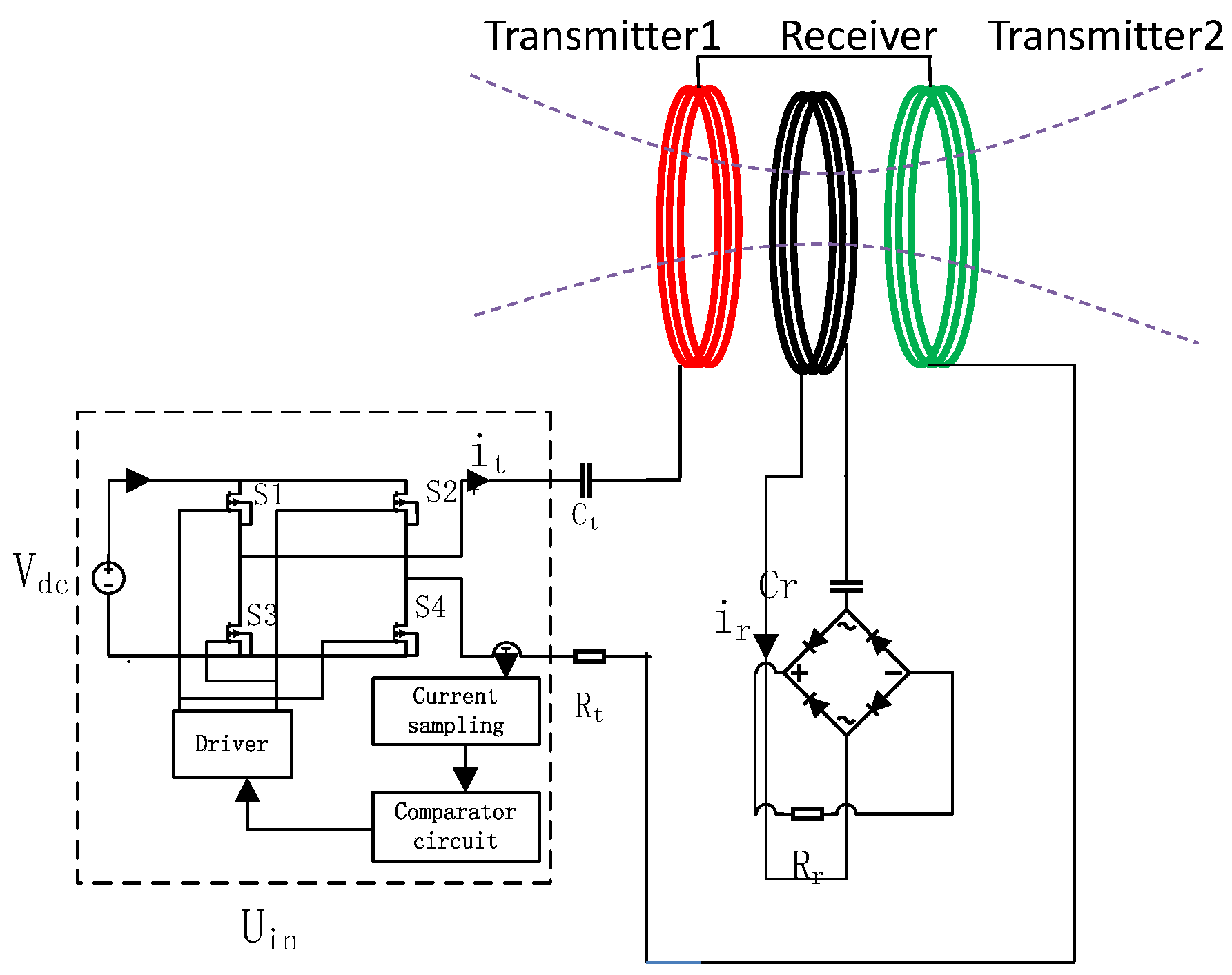
In
Figure 4, Transmitter 1 and Transmitter 2 are the transmitting coils of the two loops, and the Receiver indicates the receiving coil.
and
denote the equivalent series resistance, which for simplicity is considered constant and represents the conduction loss of the coil, power semiconductor, etc.
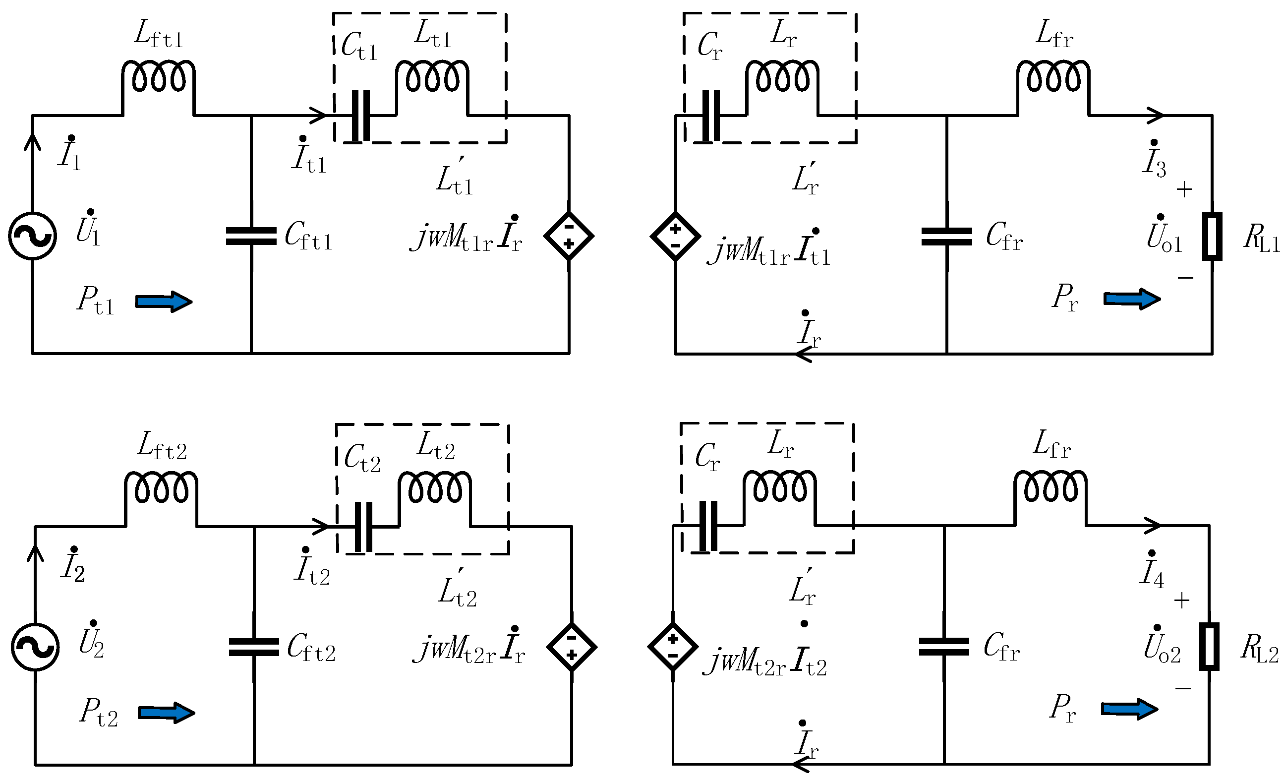
2.2. Case2 Dual Transmission Coil Wireless Power Transfer (DTCWPT)
In
Figure 5 Transmitter 1 and Transmitter 2 represent the transmitter inductances
and
.
and
represent the transmitter loop capacitances, and
is the capacitance of the receiver loop.
,
, and
represent the equivalent series resistance, which is considered constant for simplicity, and represent the conduction loss of the coil, power semiconductor, etc.
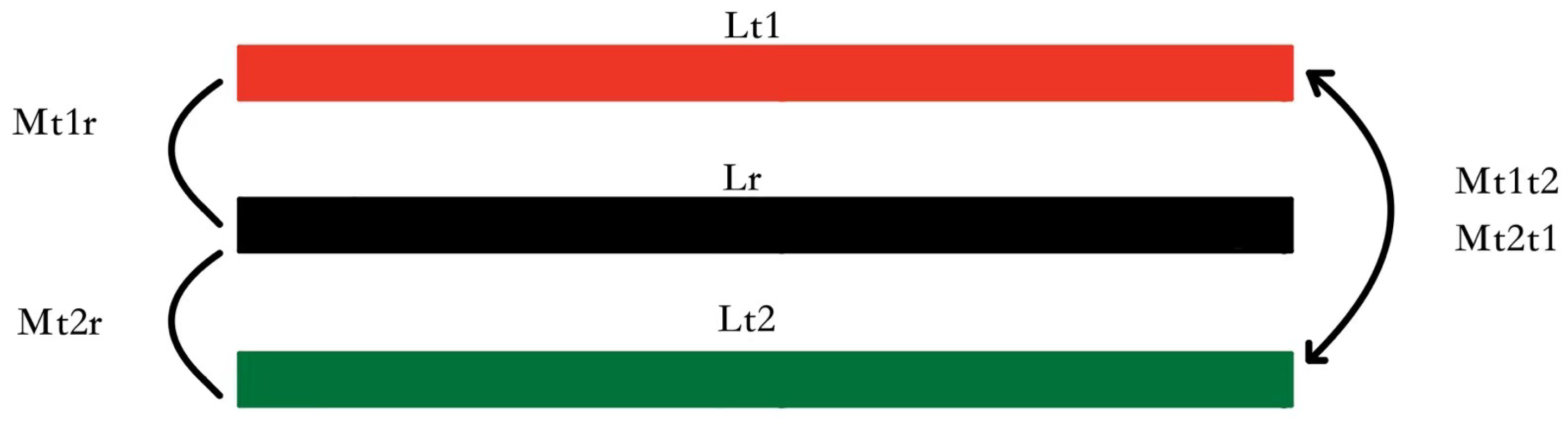
A schematic of the coupling between the three coils is shown in
Figure 6, where
denotes the mutual inductance between transmitter 1 and the receiving coil,
denotes the mutual inductance between transmitter 2 and the receiving coil, and
and
denote the mutual inductance between the two transmitter coils. On the transmitting side, the flux excited by
crosses coil
, and the amount of this flux can be expressed as
. The flux excited by
crosses coil
and the amount of this flux can be expressed as
. “S” is the area of the monopole coil, “B” represents the flux density, and since the area of the three coils is the same, it is uniformly expressed as S.
can be expressed as Equation (
1) [
26]:
The mutual inductance
between coils
and
is essentially the magnetic flux
generated by the current
in coil
, which induces energy in coil
, as shown in Equation (
2).
Figure 3 shows that the magnetic flux B of the proposed structure at the receiver coil position under equal excitation is significantly larger than that of the conventional wireless charging structure, which gives the structure a higher coupling coefficient and has a positive impact on the power and stability of the WPT system.
The structure is controlled by two controllable DC sources that can offset the mutual inductance between coils
and
and the respective self-inductance generated by [
26], which shows that the coil in the semiclosed core structure can effectively suppress magnetic leakage, reduce electromagnetic radiation, and improve the transmission efficiency in the system, as well as provide the system with good water resistance. Therefore, this structure is designed as a semiclosed system, and the conceptual diagram is shown in
Figure 7.
In practice, there are two types of misalignment in DTCWPT systems, x-misalignment (up and down) and y-misalignment (left and right), according to [
26], as shown in
Figure 3. For the proposed wireless charging system, it is difficult and inconvenient to adjust the misalignment in the x-direction. Meanwhile, reducing the y-directional misalignment by a semi-closed design is much easier to adjust. Therefore, with the semi-closed device design, the y-axis misalignment can be ignored and we choose the x-axis misalignment for analysis. The magnetic field of the coil structure can be obtained with the help of the finite element simulation, and the simulation results for a misalignment of 2 cm are shown in
Figure 8.
Figure 8a shows a schematic diagram of the magnetic field of the conventional wireless energy transmission structure, and
Figure 8b shows the proposed wireless energy transmission structure, and it can be observed from the figure that after the misalignment of the transmitting coil and the receiving coil occurs, the magnetic field at the receiver coil position of the proposed dual transmit coil structure is significantly better than that of the single transmit coil, which is consistent with the theoretical analysis.
The magnetic field of the coil structure can be obtained with the help of finite element simulation, and the simulation results are shown in
Figure 8, from which it can be observed that the received energy decreases with the increase in the misalignment distance, and the proposed dual-transmitting coil structure corresponds to a receiving coil with a significantly better magnetic field than the single-transmitting coil, which is in good agreement with the theoretical analysis.
4. System Construction
According to the theoretical analysis in
Section 3, the PT symmetry-based WPT system will get constant output power and constant transfer efficiency in the strongly coupled region. Based on this theory, a 39 W scaled-down AUV wireless energy transmission system is designed. In fact, with a reasonable design, the PT-based nonlinear wireless charging platform can charge commercial AUVs of 1 kW or more [
30]. The AUV power supply structure is not considered in the demonstration charging structure, and for the actual AUV, a DC/DC converter is needed to provide the ideal output voltage and current to meet the AUV charging requirements.
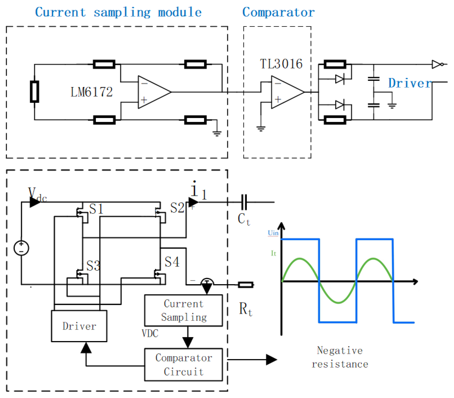
4.1. Negative Resistance Design
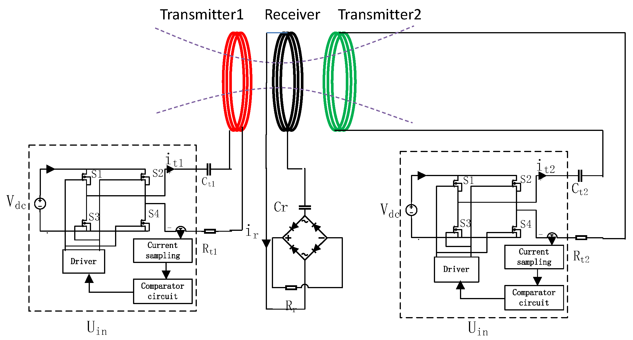
Figure 11 shows the control circuit diagram of the proposed system. In the experimental prototype, the H-bridge module can be used as a DC to AC inverter driver, and the power tubes are selected as MOSFET with a maximum dissipation of 64 W. MOSFET can operate in high frequencies with low power consumption and low switching losses, and the four complementary drivers are controlled by signals from the feedback loop, further improving the overall efficiency of the system. The control circuit is completely isolated from the signal input circuit by a high-speed optocoupler. The detailed control circuit of the negative resistance module is shown in
Figure 11. The design uses a differential amplifier implemented in the LM6172 to amplify the current sensing signal. The compensator, amplifier, overzero comparator, and H-bridge module are cascaded to generate the drive signal for the full-bridge inverter. The two transmitting loops are controlled separately by two control loops. When both control loops send a trigger signal at the same time, the same phase wireless transmission starts at the same time after the trigger signal is received at both ends, and the phase control is implemented through the MSP430 microcontroller. (TI, USA)
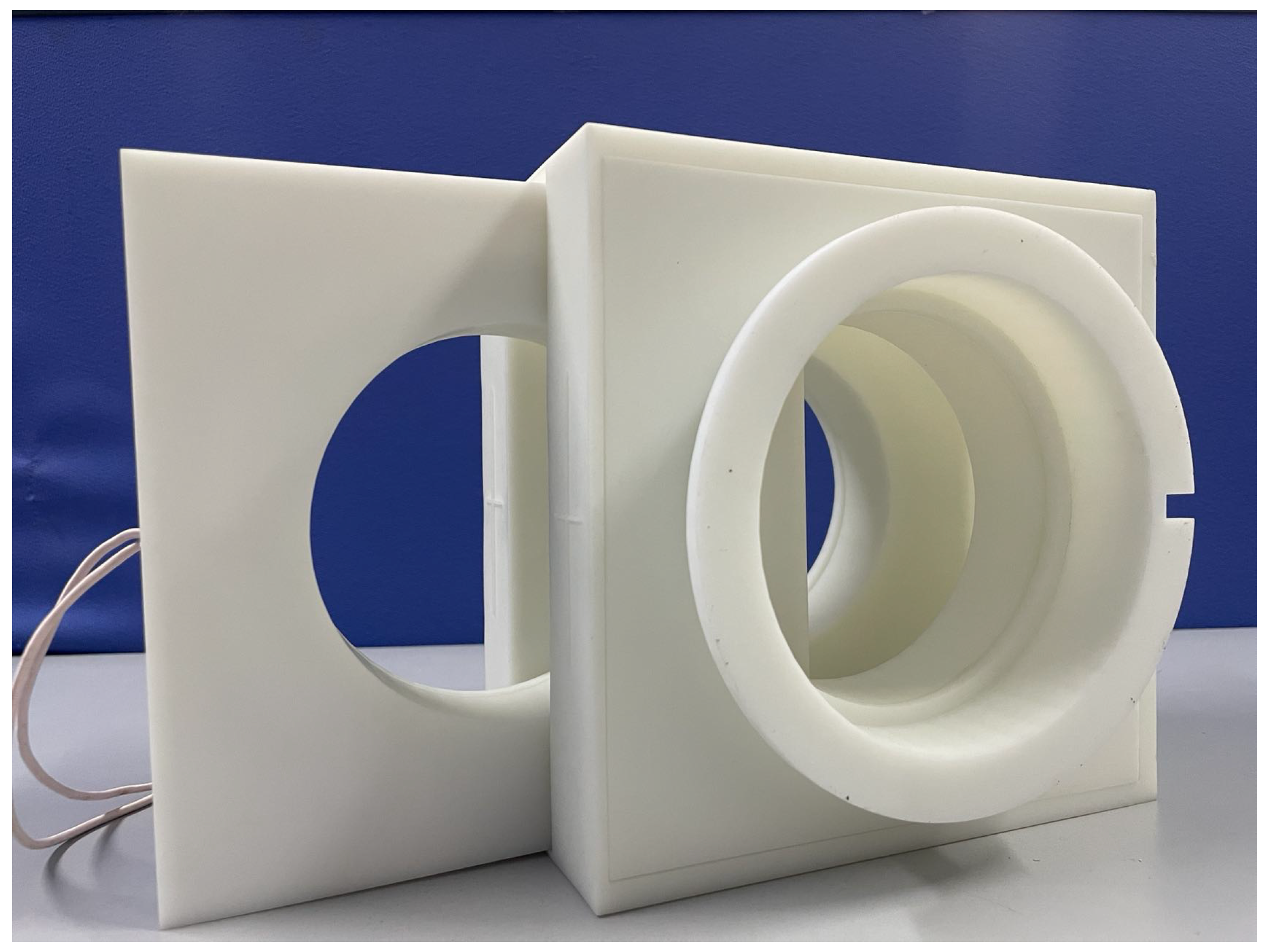
4.2. Coupled Structure Design
Electrical and physical factors need to be considered when designing the transmitting coils (T1 and T2 coils) and the receiving coils (R coils). The dimensions of the demonstration charging housing structure are 20 × 20 × 20 cm, the housing structure is shown in
Figure 12, and the inductor coils are selected from the Lietz wire (0.05 mm diameter, 1000 strands) wound magnetic core inductor and empty core inductor. In addition, the system proposed in [
31] that adds an additional inductor to the receiving circuit can extend the transmission distance, but, at the same time, the efficiency of the system is compromised. In this paper, the transmitting coil is split into two places, which is beneficial for increasing the power while ensuring the efficiency.
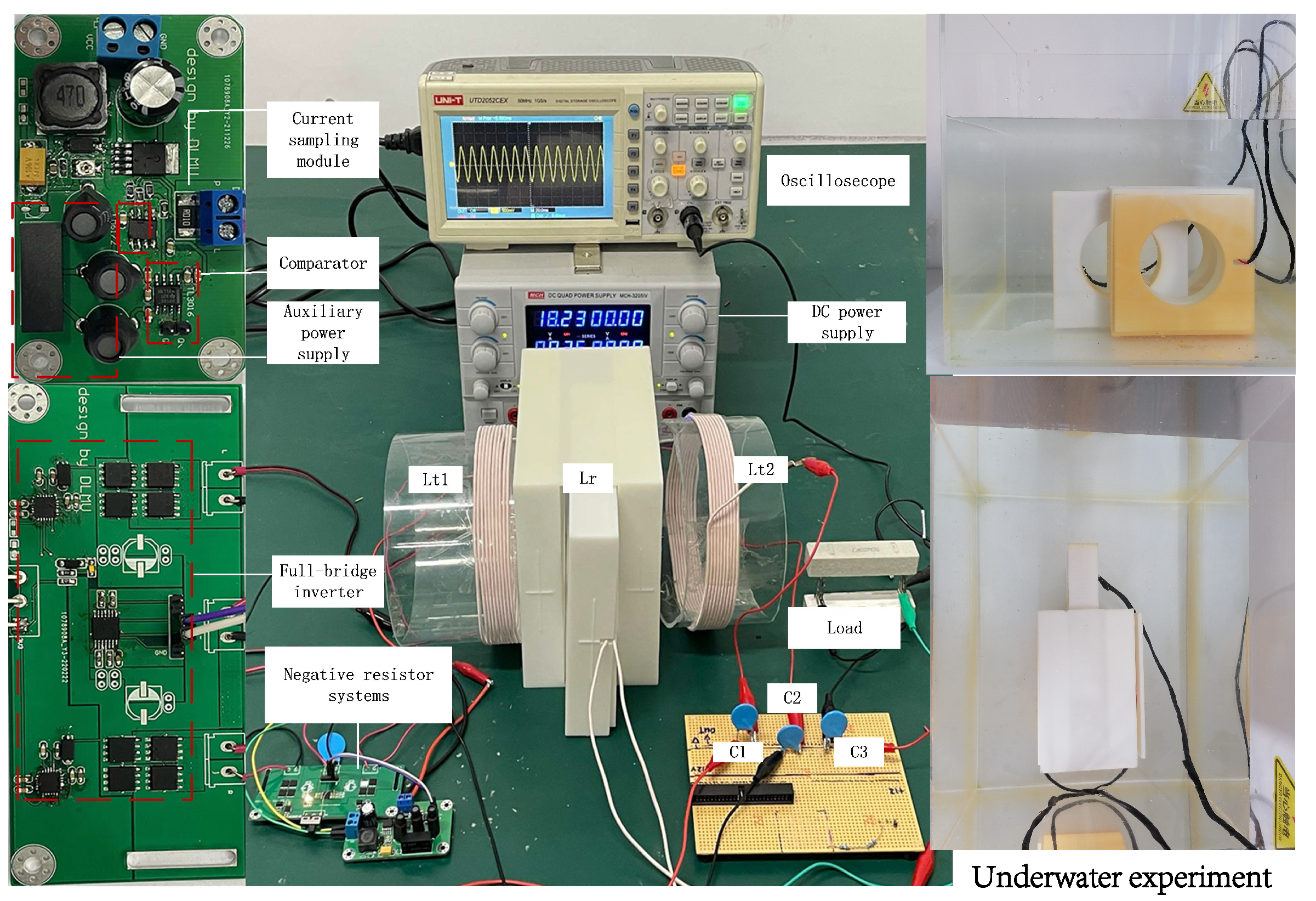
The experimental prototype built in the laboratory is shown in
Figure 13. The coupling conditions of the experiments are not fixed and are carried out under different coupling conditions. The proposed device is statically positioned on the platform to obtain accurate experimental results. The
coil is fixed, while the
coil can be adjusted laterally in the x direction, as shown in
Figure 13. Two cases are set up in the experimental part to verify the effectiveness of the proposed method. A single transmission loop structure, a double transmission loop structure and conventional radio energy transmission are proposed. However, the coupling coefficients of coils with different inductance values at the same distance are not equal. For the sake of fairness, the coil inductance values of Case 1 and Case 2 are set to the same value. Among them, Case 1 represents the case of a single transmission circuit, and Case 2 represents the case of dual transmission circuits.
4.3. Case 1 Experiments with Conventional PT-Symmetric Systems
The experimental prototype is shown in
Figure 13. The DC power supply provides the DC input voltage to the system. The compensation capacitor is a multilayer ceramic capacitor. The structure of both transmitting and receiving coils is a spatially spiral structure made of wound Lietz wires (0.05 mm diameter; 1000 strands). First, experiments with a single-loop structure were performed on the described system. The specific experimental parameters are listed in
Table 1. The inductance values of the transmit and receive coils were 56
H, the coil radius was 120 mm, and the number of turns was 10. The capacitance values of the compensation capacitors on the transmit and receive circuits were 10 nF. The natural resonant frequencies of the transmit and receive loops were set to 212 kHz, and the operating frequency of the system automatically tracked the equation
according to the variation in the coupling coefficient.
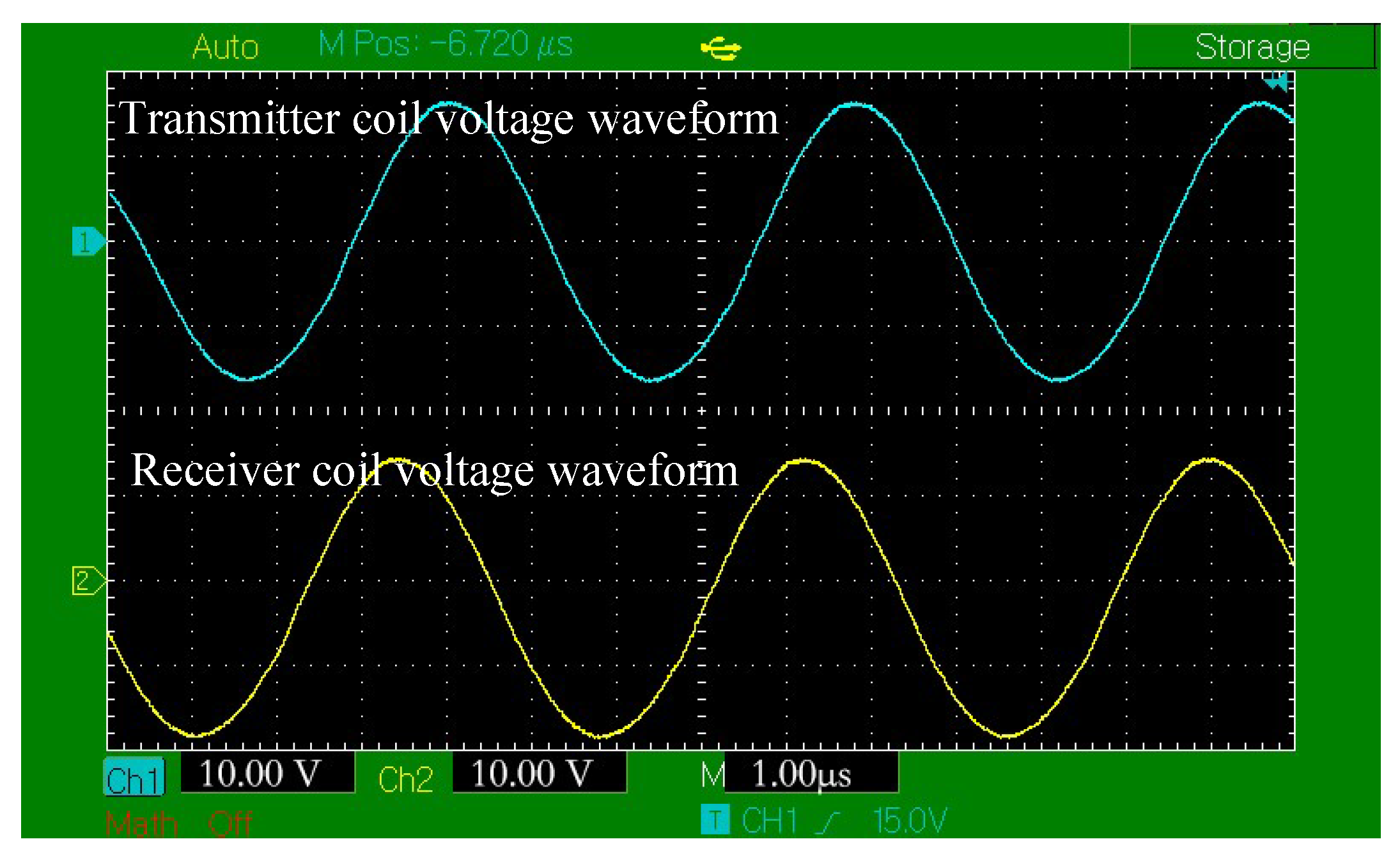
Figure 14 shows the voltage waveforms on the transmitting coil and load in Case 1 when the coil center axis is misaligned by less than 1 cm, from which it can be observed that the transmitting coil voltage and the receiving coil voltage can achieve stable transmission.
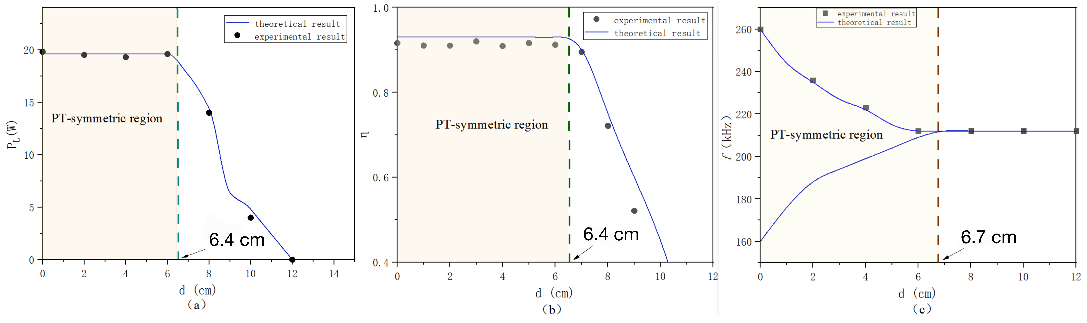
Figure 15 depicts the transmission performance and transmission distance curves of Case 1.
Figure 15a shows the curve of output power and coil misalignment degree. It can be observed that in the misalignment less than 6.4 cm, power can be transmitted stably, and the transmission power can reach 20 W.
Figure 15b shows that 6.4 cm offers a relatively stable transmission efficiency. Beyond the strong coupling range, power and efficiency show obvious changes. The experimental results are consistent with the theory. The system described in the single-loop structure is similar to the improvement strategy of the conventional transmission system, and the strength of the coupling field of the two coils is enhanced, which improves the transmission performance.
The system described in the single-loop structure is similar to an improved strategy for conventional transmission systems, with enhanced strength of the coupling field of the two coils allowing for an improvement in transmission performance.
4.4. Case 2: Dual Transmission Coil Wireless Power Transfer (DTCWPT)
As with the experiments with the single-launch loop system, the double launch loop system used the same equipment to conduct the experiments. The specific experimental parameters are listed in
Table 2.
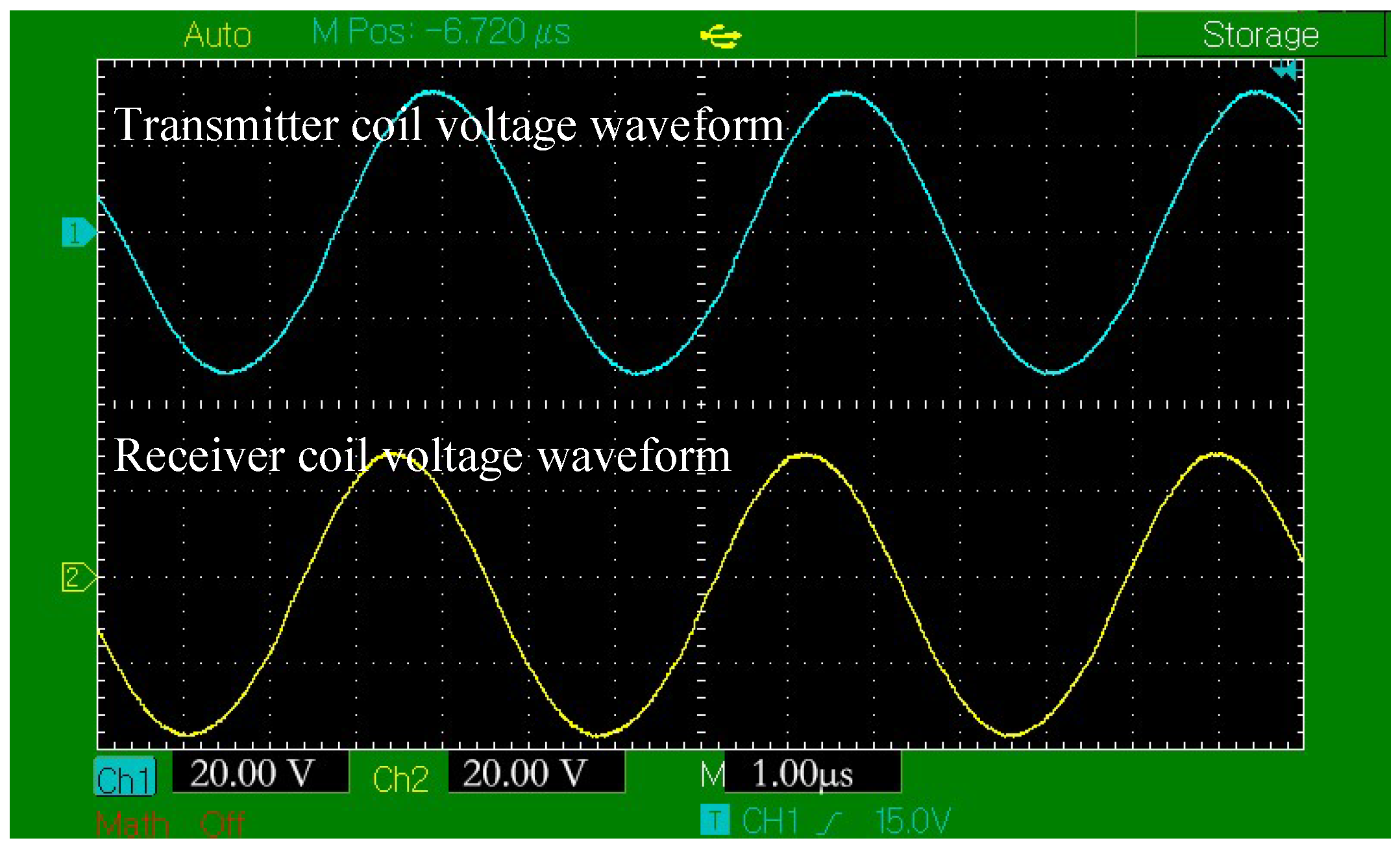
To compare the efficiency of the system at the same output power, the input voltage was set to 18 V. The semiclosed structure reduces the effect of lateral misalignment to a large extent. The output waveform of the system operating in the strongly coupled region with only the longitudinal misalignment considered is shown in
Figure 16, which shows that the voltage transmission between the transmitter and the receiver in the strongly coupled region is in accordance with the theory.
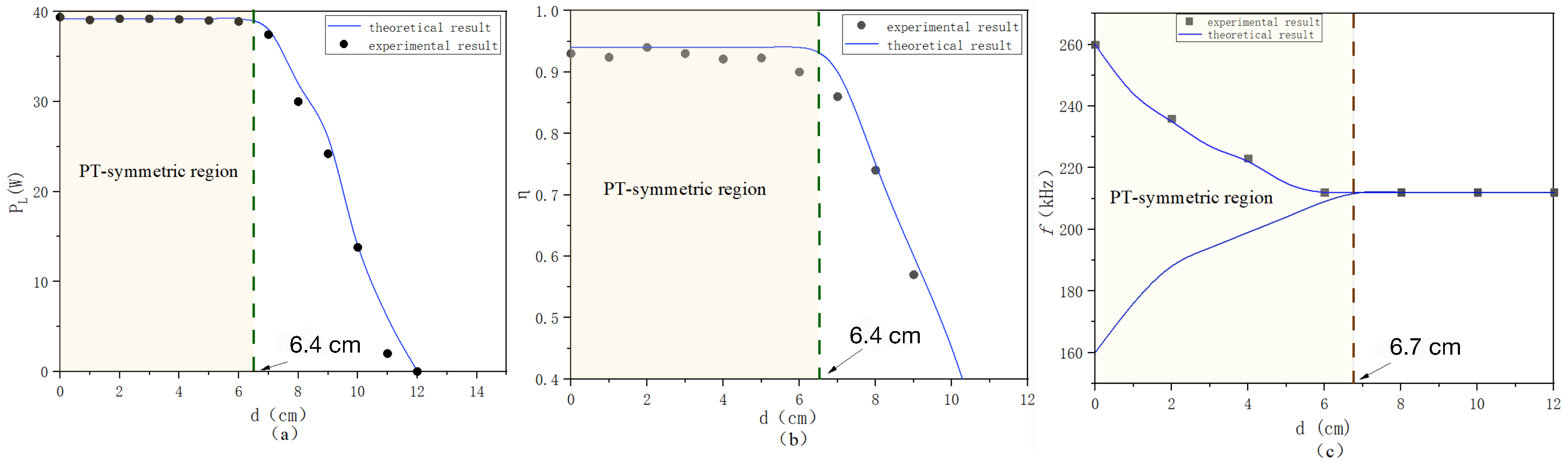
Figure 17a shows that the output power can achieve stable transmission in the strongly coupled region before the misalignment of approximately 8.1 cm, and has about twice the transmission power compared with that of Case 1, reaching 39 W.
Figure 17b gives the variation of the efficiency in the misalignment experiment, and a stable transmission efficiency can be achieved in the strongly coupled region;
Figure 17c shows the adaptive frequency of the system with the change of the coupling situation and regulation, and the experimental results are consistent with the theory.
4.5. Application Shielded Enclosures
Considering the design based on the underwater environment, where seawater generates eddy current losses at high frequencies and is not easy to analyze, we design a housing structure by applying shielding materials so that there are very few line of magnetic induction that can affect the surrounding metal objects.
In order to provide a low impedance path for the magnetic flux, the appropriate reduction in the number of turns of the coil makes the resistance drop significantly within a certain range, while the size of the inductance meets the requirements for wireless power transfer (the more turns, the higher the resistance). We can use thick shielding materials that can absorb large amounts of flux (they have high flux saturation points) to prevent the material behind the RX coil from heating up and improving the transmission efficiency. The design also shields the high-frequency strong electromagnetic interference generated during transmission from harming underwater electromagnetically equipment and the human body. Having electromagnetic shielding and electromagnetic stealth features in the military field can also greatly improve safety.
4.6. Loss Analysis
In the WPT system, the transmission efficiency of the system is a major indicator of concern. Parasitic resistances in the transmitter, receiver, and resonant components absorb energy and reduce efficiency. In addition, there are losses in the inverter and rectifier. To reduce power losses in the transmitter and receiver and to achieve low- temperature characteristics, Lietz wires are used to build the coil because of its low parasitic resistance. In addition, the filter inductor uses Lietz wires and a ferrite core. In addition, the parasitic resistance of the capacitor also needs to be as small as possible. An LCR meter is used to measure the parasitic resistance and filter inductance of the transmitter and receiver. The input power of the inverter can be calculated by obtaining the input voltage and current of the inverter through DC power source 2. The input power of the inverter minus the output power of the inverter is the energy consumed by the inverter, that is, the loss generated by the inverter.
In addition, the coil losses and inductance losses are derived from the same measurement method. The system performs loss measurements at a pure resistive light loads.
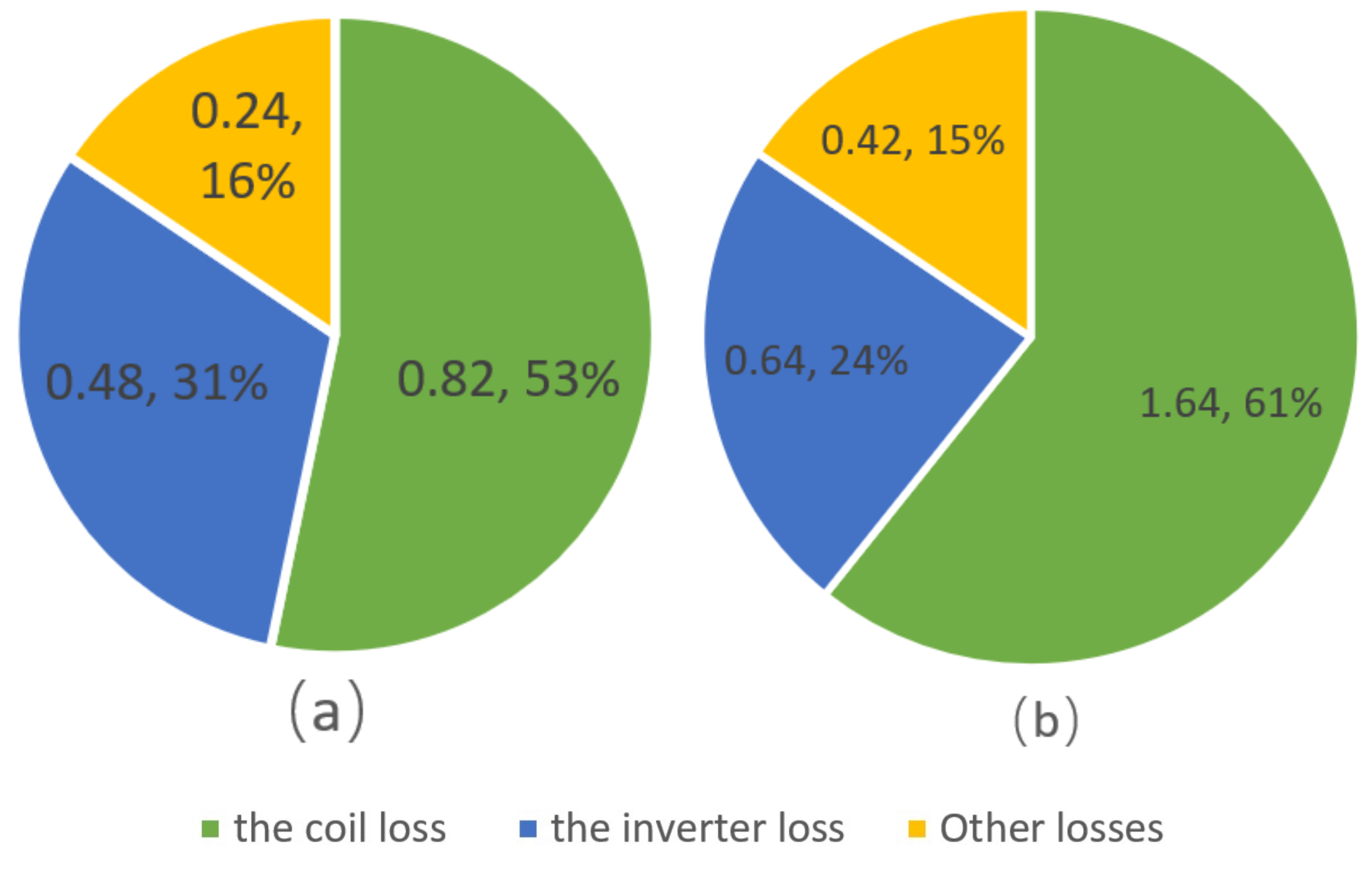
Figure 18 shows the power loss of the WPT system under different conditions.
Figure 18a shows that in Case 1, the coil loss and inverter loss are the main power losses of the system. The system efficiency is 91.6% and the total system loss is 1.54 W. The coil loss is 0.82 W, accounting for 53% of the total loss, and the inverter loss is 0.48 W, accounting for 31% of the total loss.
Figure 18b shows that in case 2, the system efficiency is 91.5%, the total system loss is 3.31 W, the coil loss is 1.98 W, accounting for 60% of the total loss, and the inverter loss is 0.91 W, accounting for 27% of the total loss. In addition, this paper implements negative resistance through a full-bridge inverter. Similar to conventional power inverters, the losses in the negative resistance are mainly MOSFET losses. In other words, the losses of the negative resistance are losses from the inverter, and the negative resistance itself does not generate additional losses.
4.7. Application Value Analysis
For a conventional WPT system, it can be observed from (10) that the total power of the system is related to the mutual inductance M, the filter inductance
, the voltages
and
, and the operating frequency
of the system. From (19), it can be observed that the total power of the proposed DTCWPT system is related to the mutual inductances
and
, the filter inductance
, the voltages
and
, and the system operating frequency
. It is not difficult to observe that when the load is
, the operating frequency
, input voltage
, filter inductance
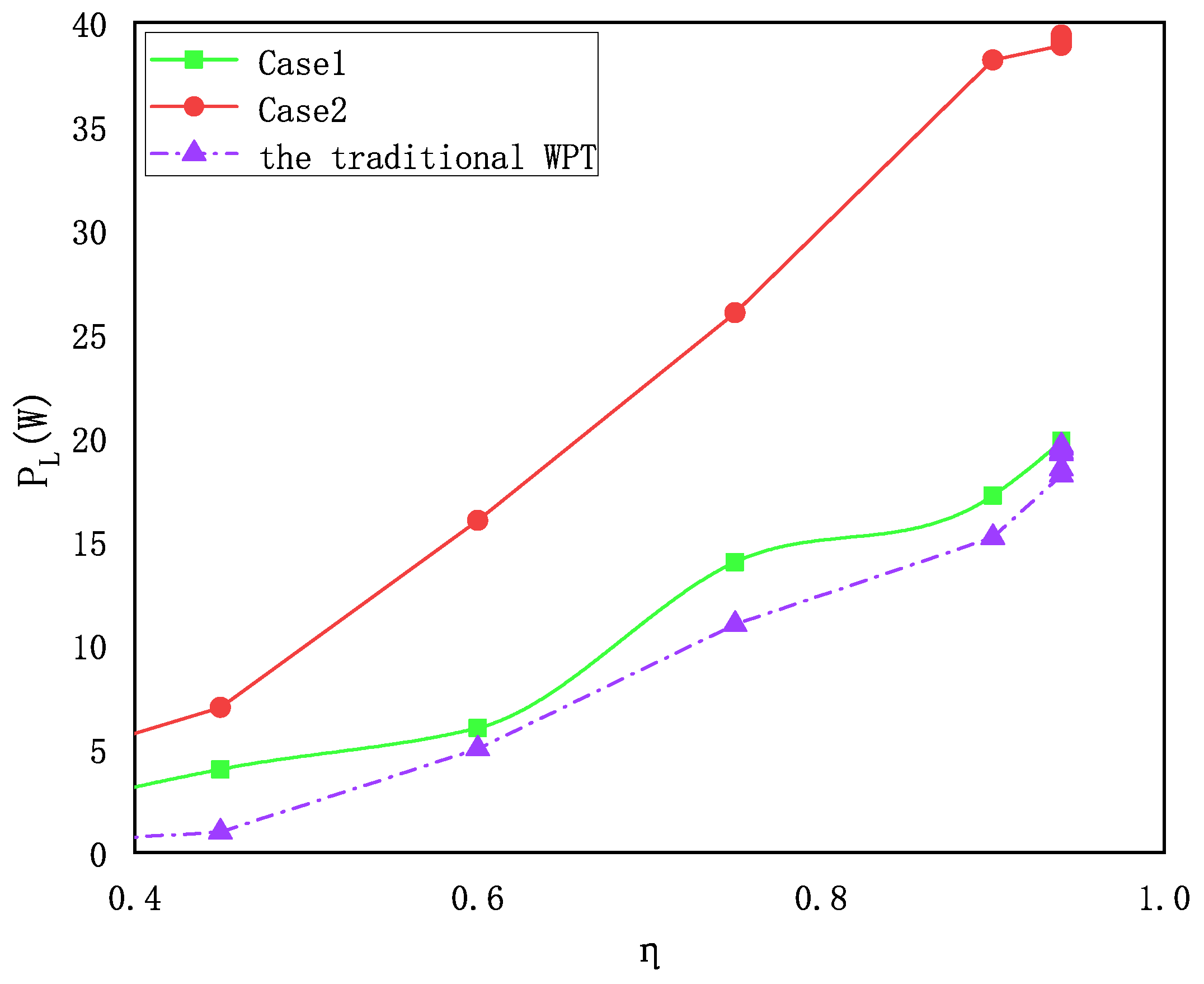
and mutual inductance of the proposed DTCWPT system are all the same as those of the conventional WPT system. The output power of DTCWPT is twice the output power of conventional WPT. Through the above experiments, the feasibility of the theory is verified. A comparison of the power and efficiency of the conventional infinite electrical energy transmission system with the proposed single-loop and double-loop structures is shown in
Figure 19, and the comparison reveals that the mentioned double-loop wireless energy transmission has significant advantages in terms of power and efficiency.
Table 3 shows the comparison between the experimental results and the results of the existing studies, which shows that the system efficiency has reached a high level, especially the DTC-WPT structure proposed in this paper, which can achieve double the output power of the input voltage level and has a great advantage in specific applications. The proposed semi-enclosed structure of the coil, which is encapsulated in a semi-enclosed structure, reduces the magnetic leakage by adding aluminum plate material to the housing, and has great advantages in the special underwater environment.
In practical applications, due to the complex underwater environment, a receiver is generally built at the stern of a ship, or the charging part is taken to be freely placed by a waterproof cable, and the coils are strongly coupled using existing magnet array adsorption or mechanical arms. This structure adopts a hollow multicoil structure, and achieves scenarios with higher mutual inductance requirements by adding a magnetic core in the center of the coil.


