Article

Thermal Model and Thermal Analysis of the Dual Drive Sliding Feed System

1
School of Mechanical Engineering, Shandong University, Jinan 250061, China
2
Key Laboratory of High Efficiency and Clean Mechanical Manufacture of Ministry of Education, Shandong University, Jinan 250061, China
*
Author to whom correspondence should be addressed.
Machines 2023, 11(12), 1084; https://doi.org/10.3390/machines11121084
Submission received: 13 November 2023 / Revised: 8 December 2023 / Accepted: 11 December 2023 / Published: 13 December 2023
(This article belongs to the Topic Designs and Drive Control of Electromechanical Machines)

Abstract

:
The dual drive sliding feed system can obtain a uniform and stable resolution at extremely low speeds and significantly reduce the system’s nonlinear friction. However, the numerous thermal sources within the system and the multipoint sliding contact during transmission result in a significant temperature rise, leading to considerable thermal deformation and errors. Moreover, the responsive mechanism of the thermal characteristics needs to be clarified. Therefore, firstly, a frictional torque model of the engagement of the screw and nut is established, and the heat generation, heat transfer, and thermal contact resistance (TCR) are solved. Then, based on the solution, a finite element thermal simulation model of the dual drive sliding feed system is established, and experiments are performed for validation. The results show that the error in temperature at the measuring point is less than 2.1 °C, and the axial thermal elongation of the screw is less than 6.2 µm. Finally, the thermal characteristics of the feeding system under various operating conditions are analyzed. The results show that the established thermal simulated model can effectively describe the dynamic thermal characteristics of the dual drive sliding feed system during operation. The effects of the rotational speed and ambient temperature on the dynamic thermal characteristics of the dual drive sliding feed system are investigated separately. The temperature increase in each part of the screw during the operation is characterized.

1. Introduction

Due to the rising demand for diversity and quality products in recent years, many high-end parts now need their surface form and precision to reach the micron or even nano-scale levels. As an important part of the machining process, the feed system’s positional accuracy directly affects the part’s final forming accuracy. However, a large amount of heat will be generated during the operation of the feed system [1,2]. Numerous studies have shown that thermal errors are difficult to control in machining due to their nonlinear and random characteristics. Thermal errors have become the most important factor affecting positioning errors [3,4]. Studying the thermal characteristics of a feed system under complex working conditions is essential for improving the forming accuracy.
Most existing feed systems use mechanical feed mechanisms; however, they are difficult to use in ultra-precision machining due to their disadvantages: mechanical clearance, friction and wear, and crawling. Therefore, Feng et al. proposed a dual drive feed system [5], which utilizes two motors rotating at approximately equal speeds in the same direction at high speeds. The worktable may get an exact micro-feed by the difference between the two speeds. The system can also adjust the worktable’s speed from extremely low to very high by switching the two motors from opposite to reverse spin. The system becomes a traditional ball screw drive system when just the screw motor is powered. This type of drive significantly reduces the impact of nonlinear friction on the feed system [6]. However, because the actuator employed in the existing dual drive feed system is a ball screw pair, when the system enters nano-scale control, the unevenness of the ball and the multibody dynamic coupling characteristics have a significant impact on motion control at very low speeds, which leads to difficulties in achieving accurate and uniform displacement under nano-scale conditions. Therefore, based on previous research [7], this paper presents a novel dual drive sliding feed system that replaces the ball screw in the conventional dual drive feed system with a low-cost sliding screw pair, aiming to achieve uniform and stable displacement resolution under extremely low-speed conditions. However, due to the addition of the nut motor and the nut bearing and the multipoint contact inside the sliding screw pair, more frictional heat will be generated during operation. Therefore, the thermal field of the dual drive sliding feed system is extremely complex for obtaining accurate and uniform feed displacement and improving the forming accuracy. Clearly, it is necessary to establish a thermal estimation model of the dual drive sliding feed system and analyze the thermal characteristics of the system.
Due to its high frictional resistance and severe wear, the standard sliding screw feed system has been restricted in its application for ultra-precision machining. Therefore, studies on the frictional properties and heat generation mechanism of sliding screws are rare. However, research on planetary roller screws, ball screws, rolling bearings, and other related transmission parts is highly developed [8,9]. Zhao et al. [10] analyzed the relationship between the friction coefficient and torque balance equation of angular contact bearing between a rolling body and a raceway. They clarified the change law of the friction coefficient under changes in external factors. Helmig et al. [11] realized the dynamic calculation of the heat transfer coefficient during bearing operation using infrared thermal imaging. Ba et al. [12] established a friction model of the ball screw feed system and designed a corresponding feed-forward compensation controller. Min et al. [13] established a finite element model of a ball screw feed system and analyzed the temperature characteristics of the system during operation. Ma et al. [14] established the motion model of a planetary roller screw, analyzed the relative motion speed of the internal contact interface, and solved the distribution of the friction forces inside it. Du et al. [15] established a finite element model of a planetary roller screw and analyzed the temperature characteristics of the system at different times and positions by considering the moving heat source during operation.
In conclusion, although research on the friction characteristics, heat generation mechanism, and thermal field characteristics of rolling ball screws and other transmission components has reached a high level of maturity, the working mode of the dual drive sliding feed system still differs significantly from that of traditional transmission components. A thermal model for a dual drive sliding feed system based on existing calculation methods cannot be established. Moreover, there is no existing research on the thermal characteristics analysis of the dual drive sliding feed system. This paper establishes a thermal model of the feed system by analyzing the friction at the engagement of the screw and nut. The influence of feed speed and ambient temperature on the dynamic thermal field characteristics of the dual drive sliding feed system are explored. The framework of this paper is organized as follows. In Section 2, the thermal boundary conditions of the dual drive sliding feed system, including the heat generation, the thermal contact resistance (TCR) between components and the convective heat transfer coefficient (CHTC) are solved separately. On this basis, a finite element simulation model of the dual drive sliding feed system is established in Section 3 to analyze the thermal characteristics of the dual drive sliding feed system. The accuracy of the established thermal estimation model in terms of temperature rise characteristics and axial deformation is also verified through experiments in Section 4. Conclusions are provided in Section 5.

2. Friction Torque Modeling of the Sliding Screw

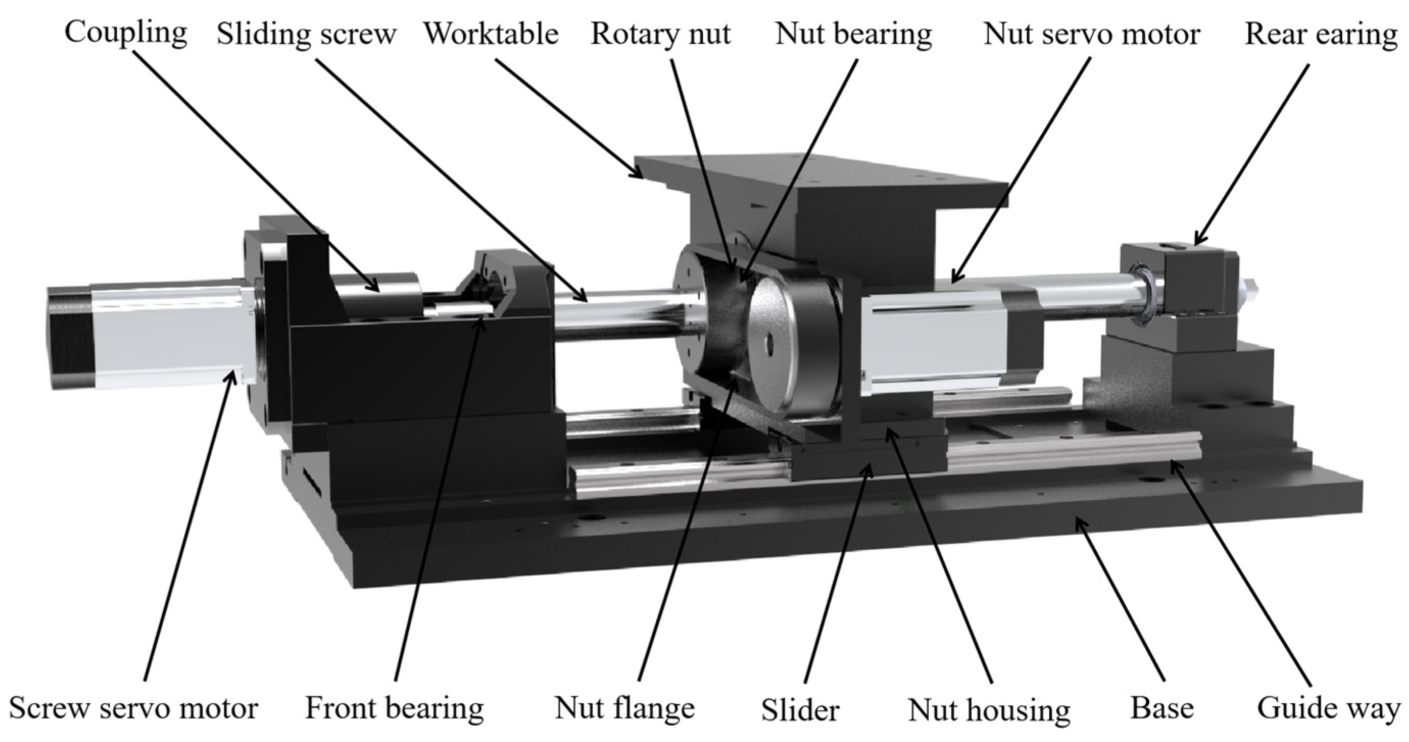
2.1. Dual Drive Sliding Feed System

The dual drive sliding feed system is illustrated in Figure 1. The main difference between this system and the traditional feed system is the addition of a motor to drive the nut. During operation, the screw and the nut rotate simultaneously, and the worktable obtains displacement through the velocity difference between the two. The distinction between the dual drive sliding feed system and the existing dual drive feed system lies in the replacement of the ball screw with a sliding screw.
The friction between components is the source of heat generation within the dual drive sliding feed system, and the friction torque is an important parameter for measuring the friction effect. Therefore, the thermal estimation model of the dual drive sliding feed system is accurately established, and the internal heat generation mechanism of the system is explored. Modeling and analyzing the frictional torque of the sliding screw are necessary. The frictional torque of a dual drive sliding feed system is affected by many factors, such as lubrication, material, and usage environment. The main reason for the frictional torque is the sliding frictional resistance that is generated by the threaded tooth contact when the relative rotation of the screw and nut occurs. Sliding friction comes from the differential sliding, elastic hysteresis, and lubrication viscosity between the screw and nut raceways. Therefore, the total friction torque of the sliding screw M T can be expressed as:
M T = ( M d + M f + M l )
where M d is the friction torque caused by differential sliding, M f is the friction torque caused by elastic hysteresis, and M l is the friction torque caused by the lubrication viscosity.
In the following, the details of each friction torque will be provided in Section 2.2, Section 2.3 and Section 2.4, respectively.

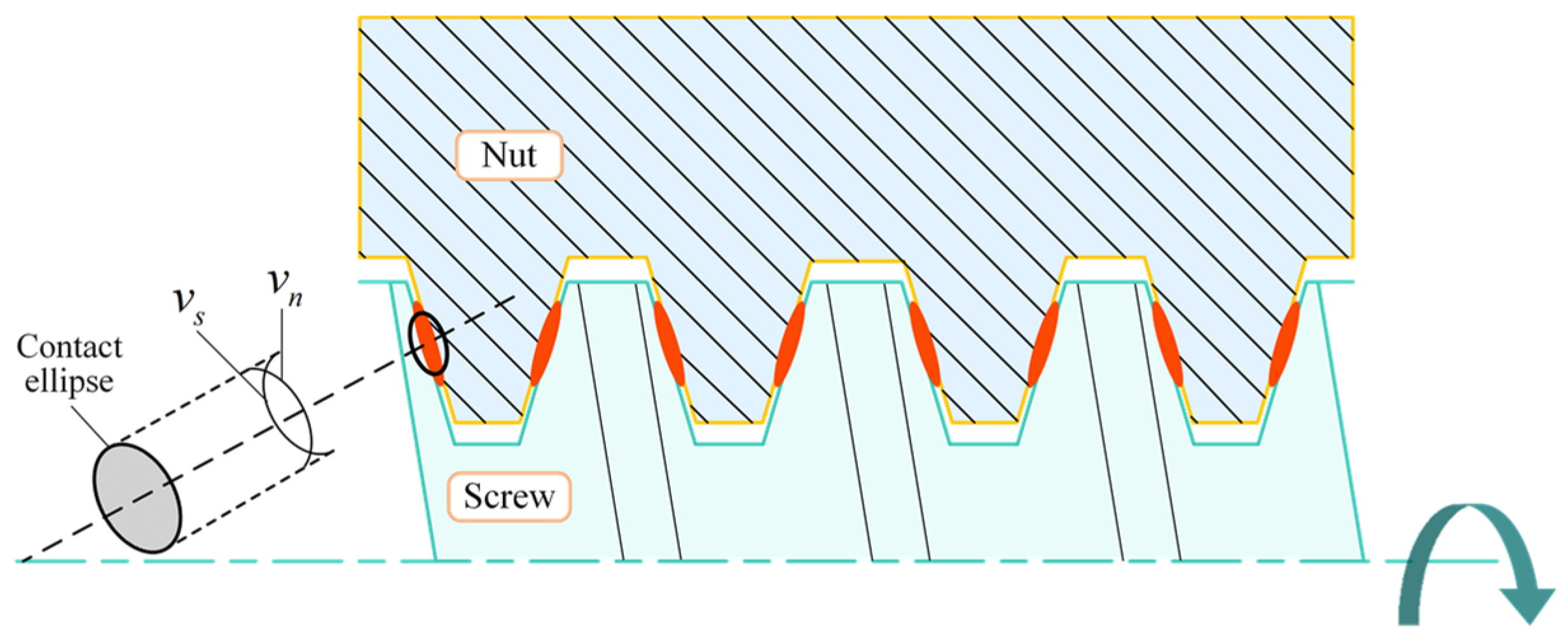
2.2. Friction Torque Caused by Differential Sliding

The contact part of the screw and nut is obtained as the dual drive sliding feed system is not rigid. According to the Hertz contact law, the contact surface of the screw and nut will produce a small contact area under the normal driving force, and its shape is an ellipse, as shown in Figure 2. The red area in the figure indicates the contact area between the screw and the nut, and the circumferential speed of the screw surface v s is proportional to the distance to its axis. Similarly, the circumferential speed of the nut surface v n is proportional to the distance to its axis. Pure rolling occurs only on two lines in the contact area. Therefore, relative sliding in opposite directions, called differential sliding, occurs at the remaining positions. The frictional moment caused by differential sliding is due to the local shear stress in the contact area. Therefore, the differential sliding friction torque M d can be expressed as [16]:
M d = τ z d A = μ P z d A
where z is the distance between the pure rolling line in the contact area and the local shear stress location, mm, μ is the differential sliding friction coefficient, P is the normal pressure in the contact area, MPa, and A is the area of contact, mm2.
Essentially, the actuator of the dual drive sliding feed system is similar to the driving mechanism of the planetary roller screw. Therefore, the differential sliding friction torque of the dual drive sliding screw pair is modeled and analyzed utilizing the friction torque modeling method of the planetary roller screw [17]. Taking the j contact area of the screw and nut as an example, the differential sliding friction of the contact area is integrated, and the differential sliding friction moment of the j contact area M d j can be obtained as follows:
M d j = 0.1 μ Q j a 2 2 R ( 1 1 ( X 2 X 4 ) d X 2 X 1 X 2 ( X 2 X 4 ) d X )
where Q j is the normal load of the j contact area, N, a is the semi-major axis of the contact ellipse, mm, R is the radius of the effective ball for Hertzian deformation (mm), and X 1 and X 2 are dimensionless parameters specified as:
X = x a X 1 = a 1 a X 2 = a 2 a
where a 1 and a 2 are the distances between the centerline of the contact ellipse and the pure rolling line on both sides (mm).
Due to the direction of the differential sliding friction torque being along the long axis of the contact ellipse, there exists an angle between it and the centerline of the screw. Consequently, in the process of engagement between the screw and the nut, the resulting differential sliding friction torque can be expressed as:
M d = j = 1 σ M d j cos α
where σ is the number of engaged thread teeth.

2.3. Frictional Moment Caused by Elastic Hysteresis

During the meshing and transmission process of double-drive sliding screw pairs, elastic deformation occurs at some positions on the thread teeth. Consequently, the strain lags behind the stress during loading and unloading, resulting in unbalanced elastic contact forces on both sides of the meshing surface. This imbalance leads to resistive torque during operation, referred to as frictional torque caused by elastic hysteresis. According to the Hertz contact law, the work done by the compressive stress when moving forward one unit distance is:
W = 3 b B P 32
where b is the short axis of the contact ellipse (mm), B is the effective axial distance of the engaging contact between balls B = 2 R (mm).
During the rotation of the screw and the nut, the system loses energy due to the elastic hysteresis phenomenon. Therefore, the friction torque can be expressed as:
M e = η W
where η is the energy loss coefficient.
Since the rotation of the dual drive sliding screw is driven through the threaded teeth, the frictional moment caused by elastic hysteresis occurs between all the engaged threaded teeth. The total elastic hysteresis frictional moment is evenly distributed among the engaged parts and can therefore be expressed as [18]:
M f = i = 1 σ 3 32 η B γ 3 E 2 ρ 3 P i 4 3
where γ is the dimensionless coefficient of the semi-short axis of the contact ellipse, E is the Young’s modulus, MPa, and ρ is the sum of the curvatures on the contact side.

2.4. Friction Torque Caused by Lubrication Viscosity

To enhance the transmission efficiency and minimize friction, lubricating grease must be injected at the meshing point of the screw and nut. Therefore, when the screw and the nut are driven by differential rotation, the system needs to overcome the friction caused by the shearing effect of the grease. Concerning the rolling bearing calculation method, the frictional characteristics at the engagement are analyzed by the elastic dynamics lubrication effect. The resistance caused by the viscosity of the lubrication F l can be solved as follows [19]:
F l = 2.86 E f t R x 2 k 0.348 G 0.022 U 0.66 W 0.47
where f t is the thermal influence coefficient, R x is the equivalent radius of curvature of the contact ellipse in the semi-major axis direction (mm), k is the equivalent radius of curvature ratio, G is the dimensionless material coefficient, U is the dimensionless velocity coefficient, W is the dimensionless load coefficient, and E is the equivalent modulus of elasticity of the screw and nut (Mpa), and can be expressed as:
E = ( 1 μ I 2 E I + 1 μ Π 2 E II ) 1
where μ I and μ Π are the Poisson’s ratios of the screw and nut, respectively, E I and E Π are the Young’s modulus of the screw and nut, respectively (Mpa).
The j contact area between the screw and the nut is taken as an example. The frictional moment caused by the lubricating viscosity of the j contact area can be obtained as:
M l j = F l j R s
where R s is the nominal radius of the screw (mm). Therefore, the friction torque caused by the lubrication viscosity is as follows:
M l = j = 1 σ M l j

3. Thermal Boundary Conditions of the Dual Drive Sliding Feed System

In the case of the feed system, a significant basis when performing a simulation of thermal characteristics is to establish accurate thermal boundary conditions. The heat transfer coefficient includes heat generation, the TCR between components, and the convective heat transfer coefficient. Existing studies have revealed that the thermal error of a feed system is influenced by external and internal heat sources. External heat sources mainly include space temperature and previous environmental memory. It is difficult to carry out a quantitative analysis. Precision machining processes mostly occur in a constant temperature and humidity environment, so such heat sources are not considered in this paper. The internal heat sources mainly include motors, bearings, screw nut, and guideways. To accurately establish the thermal behavior model of the system, it is necessary to clarify the heat generation and heat transfer mechanism. The heat generation and heat transfer mechanism of the dual drive sliding feed system are shown in Figure 3.

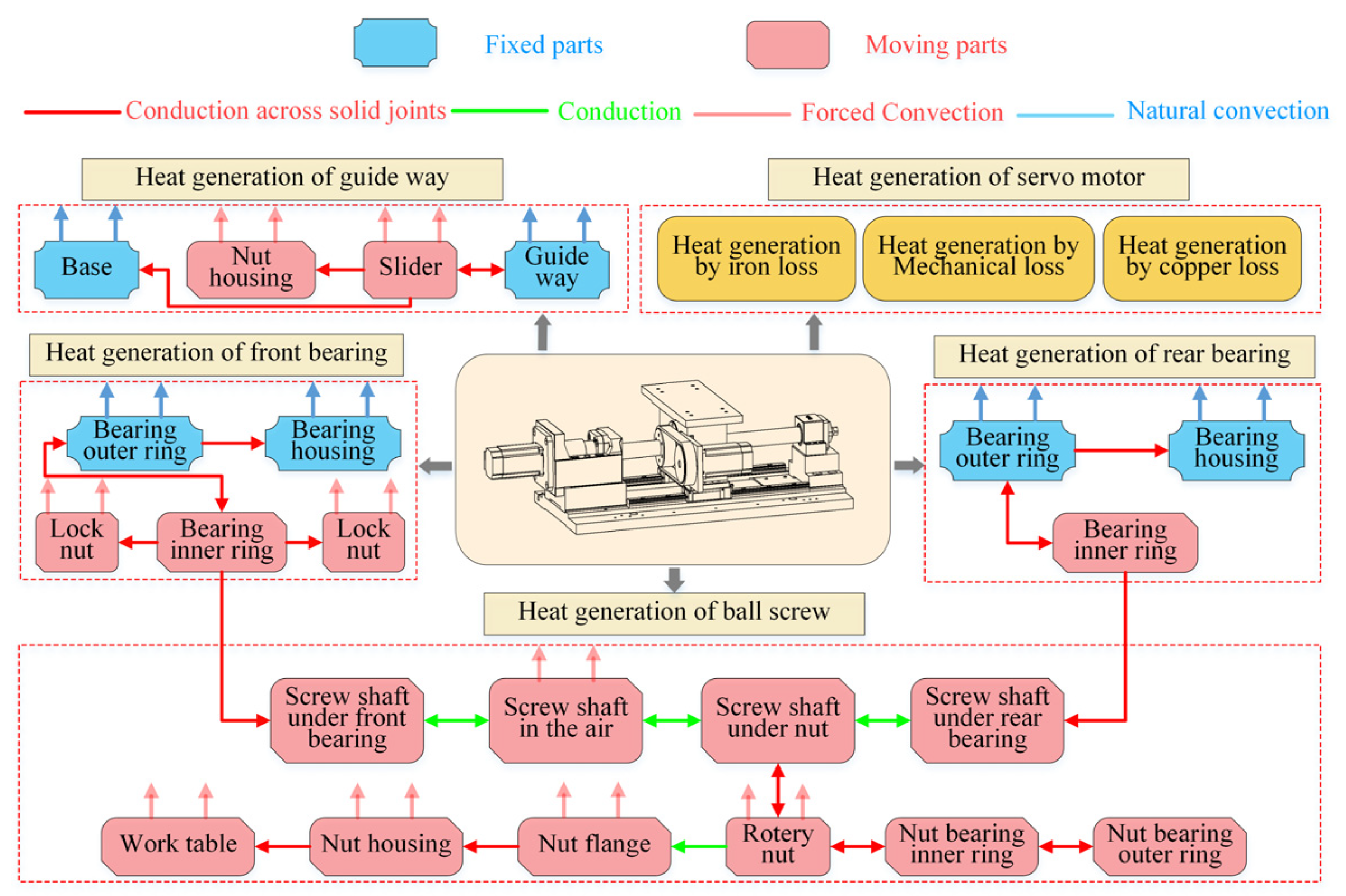
3.1. Analysis of Heat Generation

The dual drive feed system has 4 major heat sources: (1) heat generation of the guideways, (2) heat generation of the servo motors, (3) heat generation of the bearings, and (4) heat generation of the sliding screw. The sliders move continuously on the guideways; the friction caused by the rotating motion of the ball between the sliders and guideways is the main reason for the heat generation of the guideway. The heat generated by the guideways H g can be expressed as:
H g = λ f g F g v g
where f g is the friction coefficient of the guideways, F g is the vertical load carried by the guideways, N; and v g is the moving speed of the sliders relative to the guideways (m/s).
The dual drive sliding feed system has two servo motors, which drive the screw shaft and the nut. The motor heat generation can be calculated by [20]:
H m = M m n m 9550 ( 1 δ )
where M m is the output torque of the motor (N.mm), n m is the rotation speed of the motor (rpm), and δ is the mechanical efficiency of the motor.
When bearing as a rotating part, friction is the main source of heat. The heat generation of bearings can be calculated by [21]:
H b = 1.047 × 10 4 n b ( M s + M v )
where n b is the rotation speed of the bearing (rpm), M s is the load friction torque caused by the elastic lag of the material and the local differential friction, (N·mm), and M v is the viscous friction torque generated by the bearing and the lubricant (N·mm). The load friction torque can be calculated by:
M s = f 1 p 1 d b
where f 1 is the coefficient related to the type and load of the bearing, p 1 is the preload of the bearing (N), and d b is the mean diameter of the bearing (mm).
For the front bearing and nut bearing [22]:
f 1 a = 10 3 ( P 0 / C 0 ) 0 . 33
p 1 a = 1 . 4 F a 0.1 F r
where P 0 , C 0 , F a , and F r are the equivalent static load (N), the rated static load (N), axial load (N), and a radial load of the bearing (N), respectively.
For the rear bearing:
f 1 b = 9 × 10 4 ( P 0 / C 0 ) 0 . 55
p 1 b = 3 F a 0.1 F r
The viscous friction torque generated by the bearing and the lubricant can be calculated by [21]:
M v = 10 7 f 0 ( v 0 n b ) 2 / 3 d b .     v 0 n b 2000
M v = 160 × f 0 d b 3 .     v 0 n b < 2000
where f 0 is the coefficient related to the bearing type and lubrication, and v 0 is the kinematic viscosity of the lubricant inside the bearing. In this study, Equation (21) is used for the calculation.
The friction of the dual drive sliding screw is the cause of its heat generation, which is related to the total friction torque and the speed of the sliding screw. The heat generation can be expressed as [8]:
H T = M T n T 9550
where n T is the relative speed of the screw and the nut (rpm).

3.2. Analysis of Heat Transfer

The heat transfer process of the dual drive sliding feed system can be divided into two types. One is the natural convective heat transfer between the fixed surface and the surrounding air. The other is the forced convective heat transfer due to the relative motion of the parts and the air. The CHTCs of both can be expressed as [23]:
h = N u λ L s
where N u is the Nusselt number, λ is the fluid thermal conductivity (W/m·K), and L s is the component feature size (mm).
Natural convection heat transfer occurs on the surfaces of fixed components such as the bearing housing and base. The Nusselt number N u n can be calculated by:
N u n = C ( G r P r ) ε
where C and are the constants determined by the shape of the heat source and fluid conditions, G r is the Grashof number, P r is the Prandtl number, and ε is the qualitative temperature. G r can be calculated by:
G r = g β L s 3 ( T s T a ) v a 2
where g is the acceleration of gravity (m/s2), β is the volume expansion coefficient of air, T s is the surface temperature of the part (°C), T a is the ambient temperature (°C), and v a is the kinematic viscosity of the air (mm2/s).
Forced convection heat transfer occurs on the surface of the moving components, mainly including the screw shaft, worktable, nut servo motor, and other parts. The screw shaft rotates and has a spiral groove on its surface, and its Nusselt number can be calculated as:
N u s = 0.133 R e 2 / 3 P r 1 / 3
where R e is the Reynolds number. For the top and lateral surfaces of the remaining parts, the Nusselt constant N u p can be calculated by:
N u p = 0.332 R e 1 / 2 P r 1 / 3
For the front surface perpendicular to the direction of motion, the Nusselt constant N u v can be calculated by:
N u v = 0.228 R e 0.731 P r 1 / 3
The motion of the worktable of the dual drive sliding feed system is the combined motion of the screw motor and the nut motor. To analyze the thermal field characteristics of the dual drive sliding feed system, the heat generation and key heat transfer coefficients of each part of the system were calculated based on Equations (13)–(29) at an ambient temperature of 20 °C for a synthesis speed of 0.18 m/min, as shown in Table 1 and Table 2.

3.3. TCRs between Rough Contact Surfaces

The surface of the internal joint of the feed system is particularly rough at the micro level due to the processing level constraint, resulting in the so-called rough joint. When heat flows through a rough joint, it differs from heat conduction in a solid, which is hampered, and a portion of the heat is lost. The temperature will drop on both contact surfaces. Therefore, to improve the simulation accuracy of the thermal model of the dual drive sliding feed system, it is necessary to accurately describe the TCR between the rough contact surfaces inside the system. According to the previous analysis of the TCR solution by this group, the TCRs of some key bond surfaces of the dual drive sliding feed system are shown in Table 3.

4. Establishment and Verification of the Thermal Model for Dual Drive Sliding Feed System

To accurately describe the thermal characteristics of the dual drive sliding feed system and compensate for the thermal error generated by the system, it is necessary to establish a simulation model of the thermal characteristics of the feed system. The finite element method is used to simulate the system, and an experiment is carried out to verify the comparative analysis.

4.1. Finite Element Simulation Model of Dual Drive Sliding Feed System

A finite element simulation model of the dual drive feed system was created based on the TCR, heat generation, and heat transfer coefficient calculated above to analyze the thermal characteristics of the dual drive sliding feed system. To increase the solving efficiency, the following appropriate simplifications and assumptions were made:
(1)
The chamfers and some tiny parts inside the system were ignored;
(2)
The screw shaft ignores the grooves on its surface and treats it as a cylinder;
(3)
The parameters of heat generation and CHTCs obtained from the previous calculation do not vary with the movement or temperature rise of the components.
The hexahedral and tetrahedral meshes were used to mesh the model once it was imported into ANSYS. The heat sources, such as the screw and bearing, were coarsely meshed to reduce simulation error. The mesh created 152,924 nodes and 282,832 elements. The dual drive sliding feed system was subjected to the same thermal boundary conditions and material attributes as in the preceding section. Table 4 shows the material qualities of several of the system’s essential components.

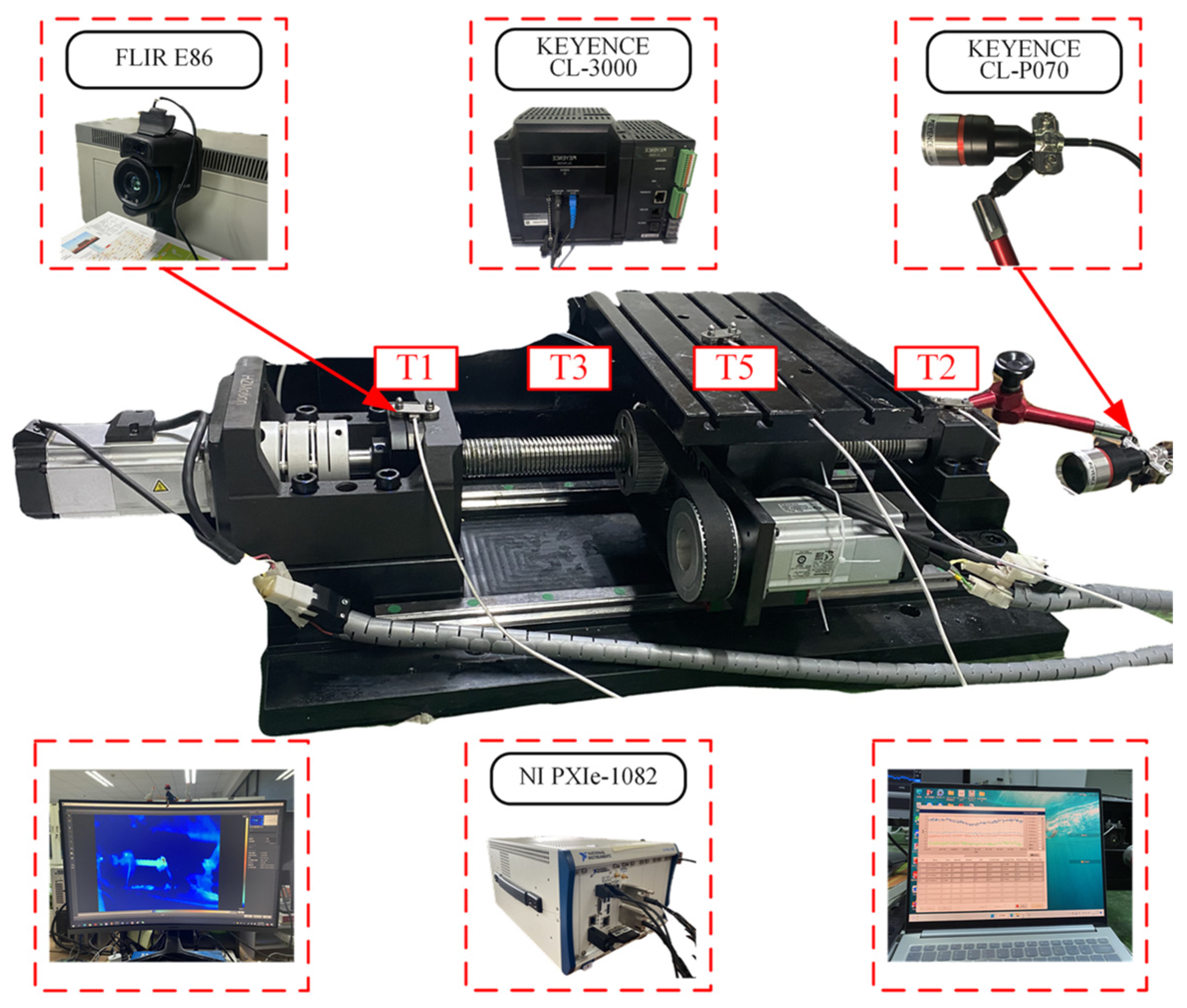
4.2. Experimental Verification Device and Scheme

To verify the accuracy of the solution of the simulation model, an experimental study on the temperature rise and deformation of the dual drive sliding feed system is necessary. Figure 4 depicts the experimental device. Concerning current studies, the temperature measurement locations that have a substantial impact on the total thermal field of the feed system were chosen [22,23,24]. The temperatures of the front bearing (T1), the rear bearing (T2), the nut flange (T3), the screw shaft (T4), the worktable (T5), the environment (T6), and the axial elongation of the screw shaft (D) were measured separately. The temperature data were acquired at T1-T3, T5, and T6 by five temperature sensors (PT100, KAIPUSEN, Xinghua, China) with a resolution of 0.1 °C. The NI PXIe-1082 was used to acquire and process the temperature data. The temperature at T4 was measured by a thermal infrared imager (E86, FLIR, Oregon, United States) with a resolution of 0.1 °C. Axial elongation (D) was measured using the laser displacement sensor (CL-3000, KEYENCE, Osaka, Japan). When the temperature rise reached 95% of the maximum temperature rise and the stable fluctuation of the value of the multiple temperature measurement points was less than 0.5 °C. The system can be considered to have reached thermal equilibrium. To minimize the influence of experimental errors on the analysis results, the values of each temperature measurement point were taken as the result of this experiment when the system reached thermal equilibrium.
To clarify the thermal characteristics of the dual drive sliding feed system, the operating conditions shown in Table 5 are used for exploratory tests. The thermal characteristics of the dual drive sliding feed system at different operating speeds and different ambient temperatures are analyzed separately. Since the working temperature of the machine tool is generally 15–25 °C, the working conditions in this paper are set the ambient temperature to 15, 20, and 25 °C.

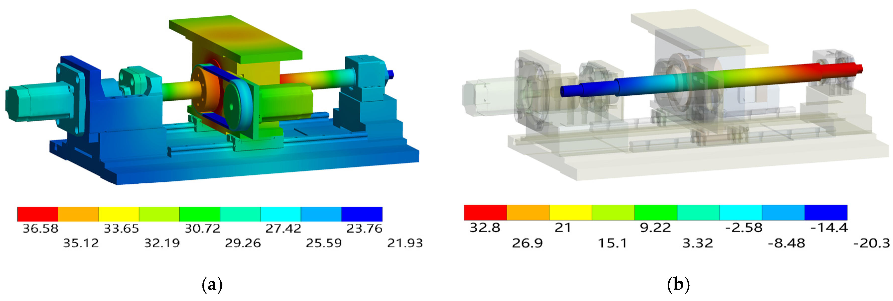
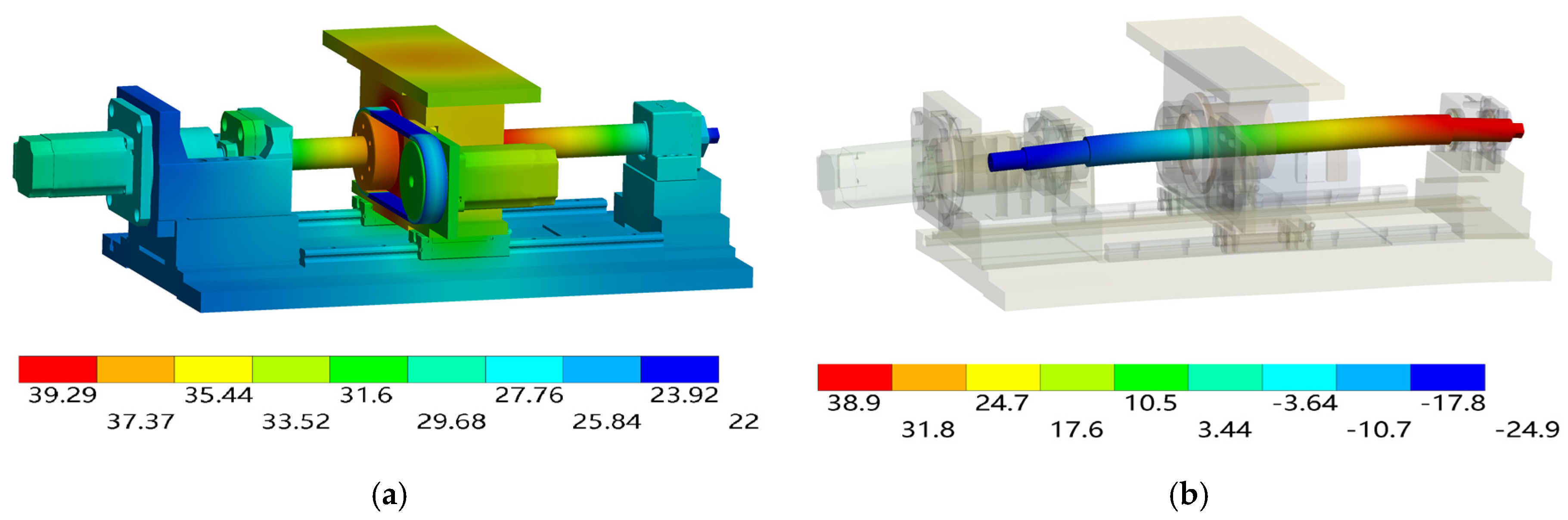
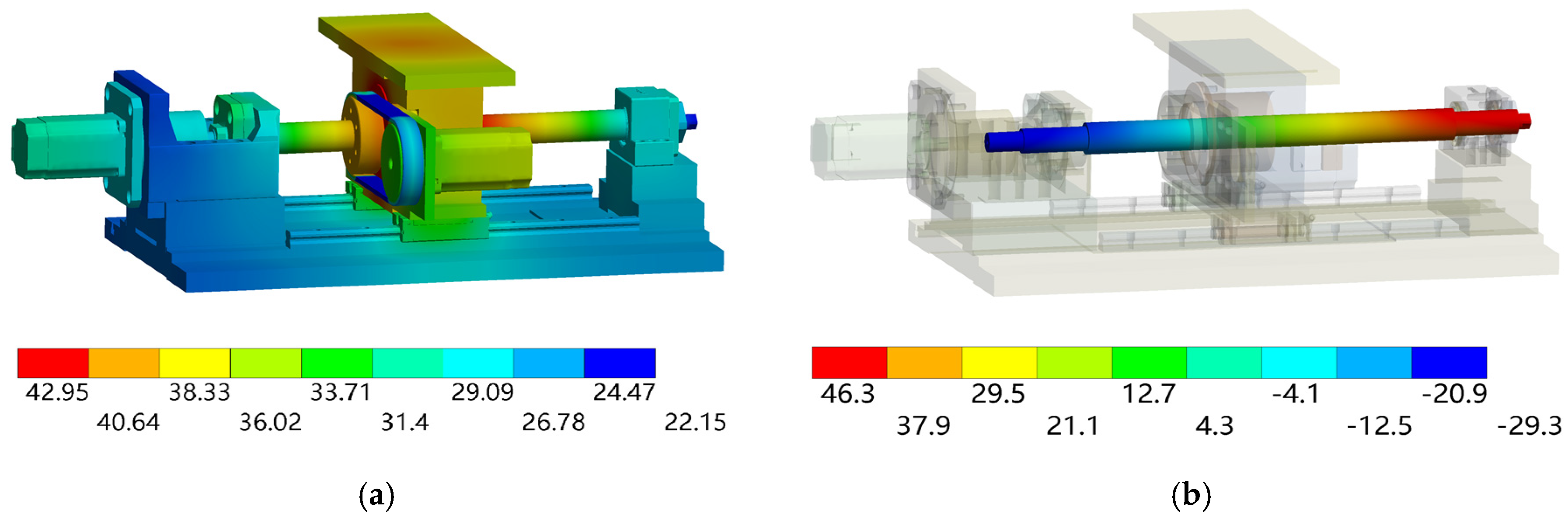
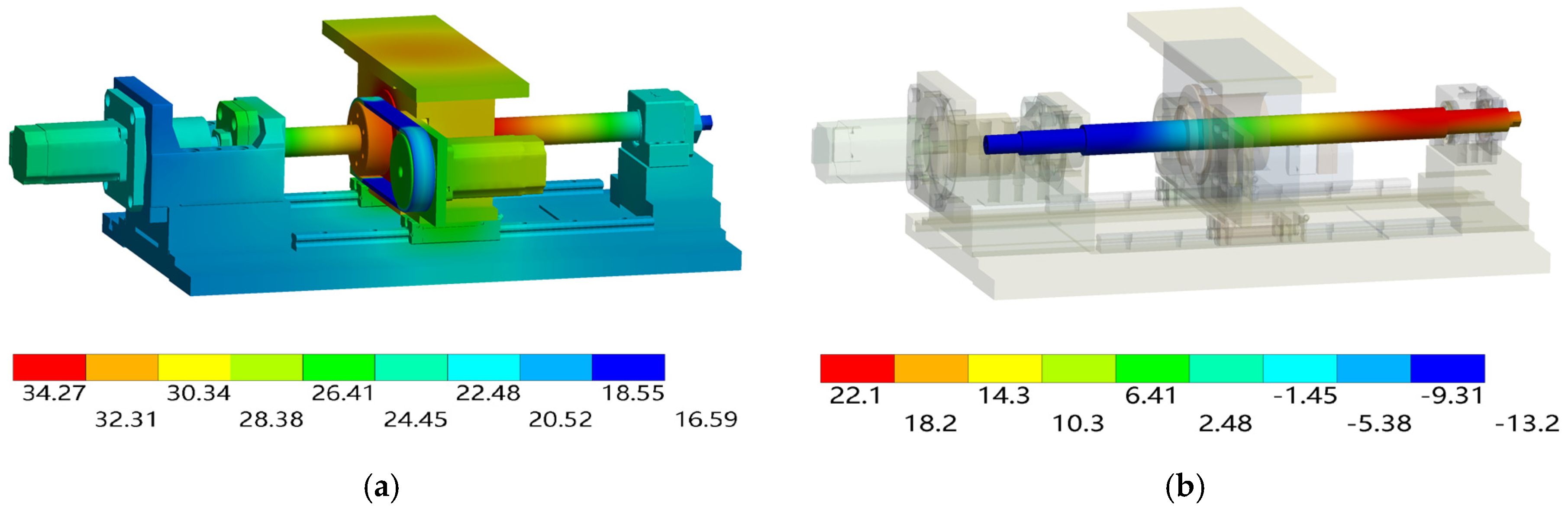
4.3. Comparison of the Simulation and Experimental Results

In the simulation platform, the nut was defined to reciprocate relative to the screw, and the worktable was moved periodically throughout the entire stroke. The transient thermal analysis end time was set to 10,800 s. The corresponding simulation parameters were set according to the five operating conditions in Table 6. The temperature field and the axial deformation of the screw after the stabilization of the dual drive sliding feed system are shown in Figure 5, Figure 6, Figure 7, Figure 8 and Figure 9.
The solved thermal field distribution shows that the dual drive sliding feed system generates heat through the friction of the contact area, which leads to thermal deformation and thermal error. Among them, the sliding friction at the engagement of the nut and screw produces the most heat and is also affected by the heat generated by the nut bearing. Moreover, because the bearing is inside the nut housing, convective heat transfer with the surrounding air does not occur. This results in heat accumulation and local high temperatures. Therefore, the highest temperature occurs at the nut. The lowest temperature appears at the synchronous belt, which is due to the material of the synchronous belt being rubber and its low heat transfer rate. The synchronous belt experiences forced convective heat transfer with the surrounding air during operation, resulting in a lower temperature than that of the other components.
From the solved axial deformation of the screw, it can be seen that the screw generates thermal elongation in the axial direction under the action of a temperature load. The deformation of the screw is affected by multiple thermal loads, such as the nut, front bearing, and rear bearing. Thermal deformation occurs in both the forward and reverse directions of the screw axis. The axial deformation at the connection between the screw shaft and the front bearing is small. The axial deformation at the connection between the screw shaft and the rear bearing is the largest. The reason is that the rear bearing is supporting and cannot limit the axial displacement of the screw at all. Given the numerous internal heat sources and the substantial heat generation of the sliding screw in the dual drive sliding feed system, the axial deformation of the system under identical operating conditions is greater than that of the conventional feed system [6].
The minimum and maximum temperatures of the thermal field of the entire dual drive sliding feed system increased with increasing rotational speed. The thermal elongation at the rear bearing also increased. Moreover, Figure 8 and Figure 9 show that the thermal field distribution, as well as the axial elongation, significantly changes after the ambient temperature changes. Therefore, the dynamic thermal characteristics of the dual drive sliding feed system are analyzed. The transient thermal field and axial elongation of the screw are analyzed for the dual drive sliding feed system. According to the preliminary experiment, the temperature increased rapidly during the initial period. Therefore, every 120 s was taken as a measurement cycle before 600 s, and every 600 s was taken as a measurement cycle after 600 s. All rotating axes operated at specified speeds during the experiment, and the worktable moved periodically throughout its entire stroke. The comparative analysis results are shown in Figure 10, the temperature deviation after the system reaches the thermal equilibrium state is shown in Table 6, and the axial thermal elongation deviation is shown in Table 7.
As shown in Figure 10, along with the increase in the system running time, the temperature of each part, as well as the axial thermal elongation, will increase. Moreover, the temperature difference at T3 is large relative to the other temperature measurement points. The reason is that T3 is the result of the superposition of two major heat sources, and the sliding screw produces more heat. As shown from the experimental and simulated comparison data for each temperature measurement point in Figure 10, the values measured in the experiment are lower than the simulation values. The reason is that the temperature sensor is attached to the component surface. There is a large thermal contact resistance, which affects the accuracy of the temperature measurements. In contrast, the deviation in the temperature measured at T4 is smaller because the temperature at T4 was measured by an infrared thermometer. There was no thermal contact resistance between the sensor and the component. In addition, this experiment used air conditioning for temperature control. Moreover, the experimental environment space is small, and the airflow was disrupted during the experiment. As a result, the accuracy of temperature collection was compromised, causing fluctuations in the experimental temperature measurement data. Comparing the characteristics of the temperature rise for each operating condition in Figure 10. It can be seen that the location with a higher temperature at the end has a faster temperature rise at the beginning due to its higher heat generation. However, the temperature rise at T5 was slower than at T3 and T4. The reason was that the T5 was not a heat source, and temperature rise could only be realized through heat transfer between components. Therefore, the temperature at T5 was also easily affected by the environment and other heat sources. So, the error between the experiment and simulation was more significant.
A comparison of Figure 10a–c reveals that the temperature increase rate at each temperature measurement point increases with increasing rotational speed. The temperature at which thermal equilibrium was reached also increased, and the thermal equilibrium time gradually decreased. The system reached a thermal equilibrium state at 120, 100, and 90 min. The heat generation and heat transfer of the system reached a dynamic equilibrium state. However, the increase in each part is different. Because the temperature at the engagement point between the screw and the nut was the highest, the temperature increase in the surrounding parts was greater. The temperature increase in the regions away from the meshing was low, as shown in T1 and T2 in the figure.
Comparing Figure 10b,d,e, it can be seen that the influence of ambient temperature on the temperature characteristics of the feed system was significant. When the ambient temperature was high, the heat generated by the system was more difficult to dissipate, resulting in a faster temperature rise. On the contrary, when the ambient temperature was low, the system can more easily dissipate heat, resulting in a slower rate of temperature rise. The ambient temperature will affect the time for the feed system to reach thermal equilibrium. At an ambient temperature of 25 °C, the dual drive sliding feed system reached thermal equilibrium at 110 min. At an ambient temperature of 15 °C, the dual drive sliding feed system reached thermal equilibrium at 70 min. It can be seen that at a higher ambient temperature, the feed system needs longer to achieve thermal equilibrium due to the difficulty of heat dissipation. The feed system can achieve heat equilibrium with the environment at a lower ambient temperature more quickly.
Comparing Figure 10c,e,f, the temperature field of condition III was similar to that of condition V when the thermal equilibrium state is reached. However, due to the difference in ambient temperature, the final axial thermal elongation of the screw was 29 µm. This once again shows that the ambient temperature has an essential influence on the thermal elongation of the feed system. Therefore, the feed system’s regular operation and precision stability must be ensured. Not only can the internal heat generation be controlled, but the ambient temperature should also be controlled within the appropriate range.
Table 6 and Table 7 show the key temperature measurement points of the dual drive sliding feed system. The deviation in the temperature simulation of the thermal model was less than 2.1 °C, and the error in the axial elongation of the screw was less than 6.2 µm, which proves the effectiveness of the built thermal simulation model. It is shown that the developed thermal simulation model can more accurately describe the thermal characteristics of the dual drive sliding feed system. The error in the axial thermal elongation of the screw will be slightly greater than the error at each temperature measurement point. The reason is that the axial elongation of the screw is the result of the combined action of all the heat sources in the feed system and the environmental conditions. The deviation results at several key temperature measurement points do not fully represent the final axial deformation deviation of the screw. Therefore, a more accurate simulation solution model was established, laying the foundation for thermal error modeling. The key temperature measurement points of the dual drive feed system should be further optimized, and the thermal boundary conditions of the system should be optimized.
Thermal simulation can obtain more operational process data than experiments can, thus providing insight into the thermal characteristics of the feed system. Operation condition I is taken as an example based on the transient thermal analysis of the feed system. The temperature field of the screw shaft with respect to time and position changes is determined. This is shown in Figure 11.
As shown in Figure 11, over time, all the parts of the screw have different degrees of temperature rise. The temperature in the middle of the screw is the highest, and the temperature at both ends is the lowest. The axial variation along the screw is from low to high and back again. The temperature at both ends is approximately symmetrical relative to the middle. The conventional screw axial temperature distribution is the opposite of the dual drive sliding feed system. The axial temperature distribution of the conventional screw is low in the middle and high at both ends [25]. The reason for this difference is that the dual drive sliding feed system utilizes a sliding screw, which results in greater heat generation. In addition, a bearing is added inside the nut, and the nut motor affects the distribution of the temperature field during operation. Therefore, the temperature rise of the screw should be controlled, and the axial deformation should be reduced. Subsequently, the structure of the dual drive sliding feed system should be further optimized to improve the temperature field distribution.

5. Conclusions

To accurately depict the thermal field characteristics of a dual drive sliding feed system under complex heat source effects and to elucidate the response mechanism of temperature rise and thermal deformation. In this study, the dynamic thermal characteristics of the system are explored by establishing a thermal simulation model and verifying the analysis with the experimental results. Based on the results and analysis, the following conclusions can be drawn:
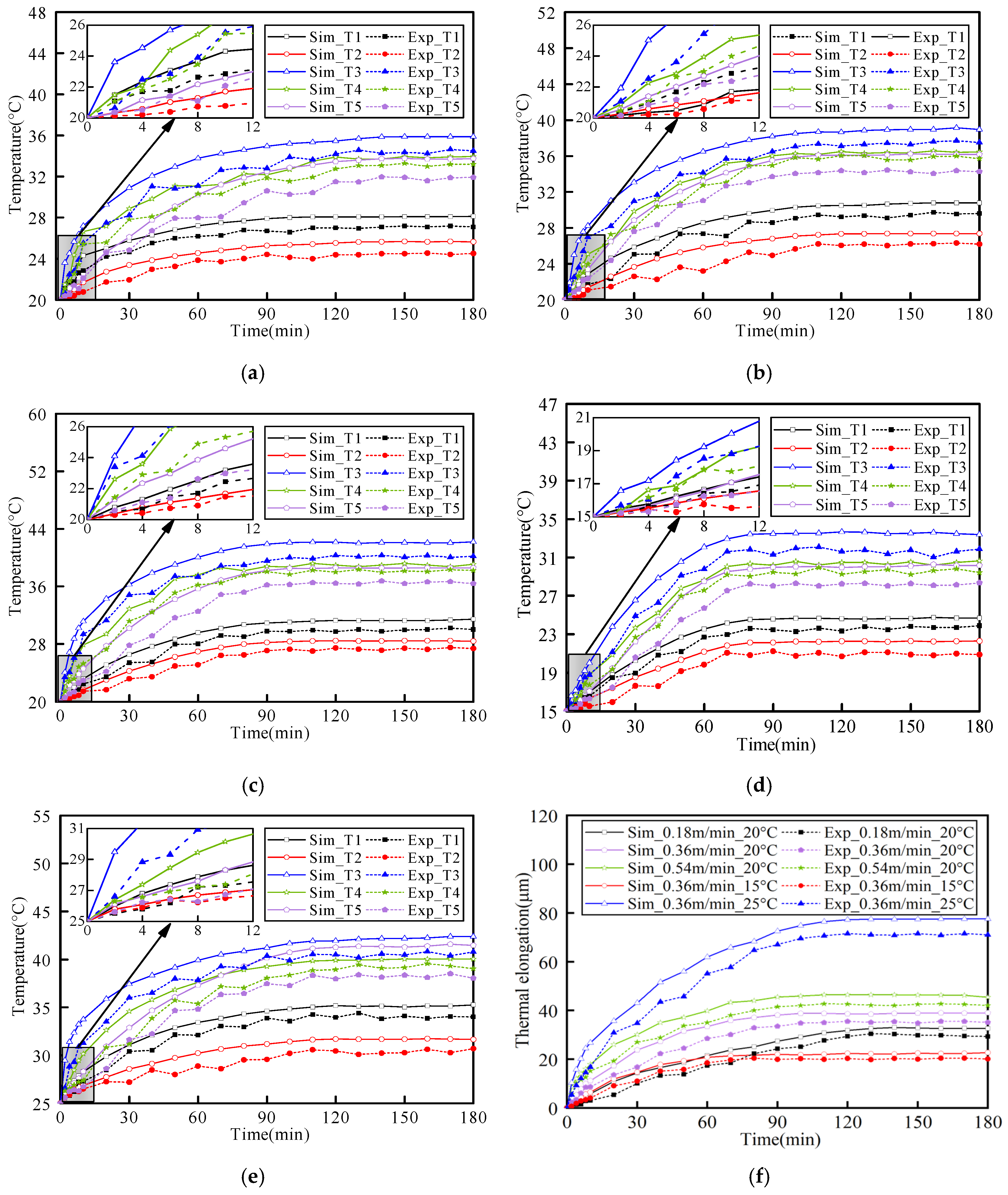
  • The established thermal simulation model can effectively describe the dynamic thermal characteristics of the dual drive sliding feed system. By comparing the temperature rise and thermal elongation under simulation and experimental conditions, it can be concluded that the temperature rise deviation under five operating conditions is less than 2.1 °C, and the error in the axial thermal deformation of the screw is less than 6.2 µm. The established thermal characteristic simulation model can effectively describe the thermal dynamic response characteristics of the dual drive sliding feed system during operation.
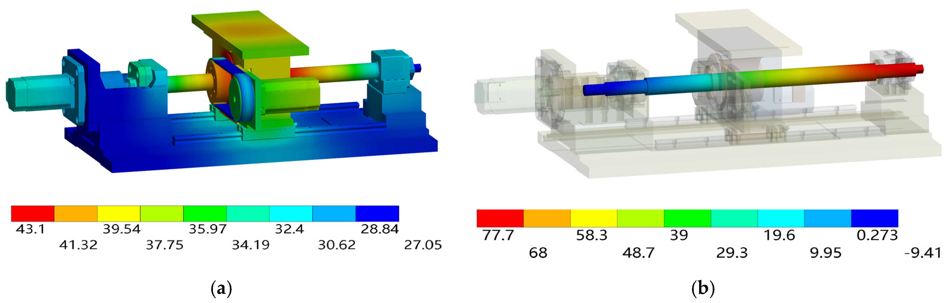
  • The thermal field distribution and axial deformation of the dual drive sliding feed system differ from those of conventional feed systems. Due to the difficulty of heat dissipation and the combined effect of the screw and nut bearings, the main heat distribution region of the dual drive feed system is at the nut. Given the numerous heat sources in the system and the significant temperature increase in the sliding screw, the axial deformation of the screw in the dual drive sliding feed system is greater than that in the conventional feed system under the same operating conditions.
  • The thermal characteristics of a dual drive sliding system are significantly influenced by both rotational speed and ambient temperature. An increase in rotational speed results in a faster rate of temperature rise and a shorter time to reach thermal equilibrium. Conversely, higher ambient temperatures lead to a quicker temperature rise and a longer time to achieve thermal equilibrium. The ambient temperature also has a significant impact on the axial deformation of the screw. Even when the temperature field is similar, substantial differences in the axial thermal elongation of the screw can occur due to varying ambient temperatures.
This study investigates the temperature and deformation field distributions of a dual drive sliding system under various operating conditions and describes the dynamic thermal characteristics of the system. This research provides a foundation for temperature rise and deformation control and guidance for structural optimization and installing cooling systems. This work also lays the foundation for developing data-driven models to realize dynamic thermal error compensation. However, due to the use of empirical formulas in establishing thermal models, there are deviations in the simulation results. Future work should consider optimizing the system’s thermal boundary conditions to further improve the thermal model’s accuracy.

Author Contributions

H.L. (Hui Li): investigation, software, writing—original draft. H.L. (Haiyang Liu): conceptualization, data curation, formal analysis, writing—review and editing, supervision. X.F.: funding acquisition, writing—review and editing. Y.L.: methodology. M.Y.: validation. A.W.: validation. All authors have read and agreed to the published version of the manuscript.

Funding

This work was supported by the Shandong Provincial Natural Science Foundation (grant number ZR2019MEE003).

Data Availability Statement

Data supporting this study are included within the article.

Conflicts of Interest

The authors declare that they have no known competing financial interest or personal relationships that could have appeared to influence the work reported in this paper.

References

  1. Li, Z.-J.; Tan, Z.; Chen, Y.; Lu, Z.-C.; Fan, Y.-C. Thermal error prediction of ball screw feed system based on inverse heat transfer analysis. Int. J. Adv. Manuf. Technol. 2022, 122, 2607–2624. [Google Scholar] [CrossRef]
  2. Li, Y.; Wei, W.; Su, D.; Wu, W.; Zhang, J.; Zhao, W. Thermal characteristic analysis of ball screw feed drive system based on finite difference method considering the moving heat source. Int. J. Adv. Manuf. Technol. 2020, 106, 4533–4545. [Google Scholar] [CrossRef]
  3. Lei, M.; Yang, J.; Wang, S.; Zhao, L.; Xia, P.; Jiang, G.; Mei, X. Semi-supervised modeling and compensation for the thermal error of precision feed axes. Int. J. Adv. Manuf. Technol. 2019, 104, 4629–4640. [Google Scholar] [CrossRef]
  4. Liu, J.; Ma, C.; Wang, S.; Wang, S.; Yang, B.; Shi, H. Thermal boundary condition optimization of ball screw feed drive system based on response surface analysis. Mech. Syst. Signal Process. 2019, 121, 471–495. [Google Scholar] [CrossRef]
  5. Du, F.; Zhang, M.; Wang, Z.; Chen, Y.; Feng, X.; Li, P. Identification and compensation of friction for a novel two-axis differential micro-feed system. Mech. Syst. Signal Process. 2018, 106, 453–465. [Google Scholar] [CrossRef]
  6. Yang, H.; Xing, R.; Du, F. Thermal error modelling for a high-precision feed system in varying conditions based on an improved Elman network. Int. J. Adv. Manuf. Technol. 2020, 106, 279–288. [Google Scholar] [CrossRef]
  7. Lu, Z.; Feng, X.; Su, Z.; Liu, Y.; Yao, M. Friction Parameters Dynamic Change and Compensation for a Novel Dual-Drive Micro-Feeding System. Actuators 2022, 11, 236. [Google Scholar] [CrossRef]
  8. Xu, Z.Z.; Liu, X.J.; Kim, H.K.; Shin, J.H.; Lyu, S.K. Thermal error forecast and performance evaluation for an air-cooling ball screw system. Int. J. Mach. Tools Manuf. 2011, 51, 605–611. [Google Scholar] [CrossRef]
  9. Qiao, G.; Liu, G.; Ma, S.; Wang, Y.; Li, P.; Lim, T.C. Thermal characteristics analysis and experimental study of the planetary roller screw mechanism. Appl. Therm. Eng. 2019, 149, 1345–1358. [Google Scholar] [CrossRef]
  10. Zhao, C.J.; Yu, X.K.; Huang, Q.K.; Ge, S.D.; Gao, X. Analysis on the load characteristics and coefficient of friction of angular contact ball bearing at high speed. Tribol. Int. 2015, 87, 50–56. [Google Scholar] [CrossRef]
  11. Helmig, T.; Kneer, R. A novel transient infrared-thermography based experimental method for the inverse estimation of heat transfer coefficients in rotating bearings. Int. J. Therm. Sci. 2021, 167, 107000. [Google Scholar] [CrossRef]
  12. Bui, B.D.; Uchiyama, N.; Simba, K.R. Contouring control for three-axis machine tools based on nonlinear friction compensation for lead screws. Int. J. Mach. Tools Manuf. 2016, 108, 95–105. [Google Scholar] [CrossRef]
  13. Min, X.; Jiang, S. A thermal model of a ball screw feed drive system for a machine tool. Proc. Inst. Mech. Eng. Part C J. Mech. Eng. Sci. 2011, 225, 186–193. [Google Scholar] [CrossRef]
  14. Ma, S.; Wu, L.; Liu, G.; Fu, X. Local contact characteristics of threaded surfaces in a planetary roller screw mechanism. J. Struct. Mech. 2020, 48, 1–26. [Google Scholar] [CrossRef]
  15. Du, C.; Liu, G.; Qiao, G.; Ma, S.; Cai, W. Transient thermal analysis of standard planetary roller screw mechanism based on finite element method. Adv. Mech. Eng. 2018, 10, 1687814018812305. [Google Scholar] [CrossRef]
  16. Houpert, L. Numerical and analytical calculation in ball bearings. Proc. Congr. Roulements Toulouse Toulouse 1999, 5–7, 1–15. [Google Scholar]
  17. Qiao, G.; Liu, G.; Ma, S.; Shi, Z.; Wang, Y.; Lim, T.C. An improved thermal estimation model of the inverted planetary roller screw mechanism. Proc. Inst. Mech. Eng. Part C J. Mech. Eng. Sci. 2018, 232, 4430–4446. [Google Scholar] [CrossRef]
  18. Yang, J.J. Effect of Preload on Axial Deformation and Friction of Planetary Roller Screw. J. Mech. Transm. 2011, 35, 16–22. [Google Scholar]
  19. Olaru, D.; Puiu, G.C.; Balan, L.C.; Puiu, V. A New Model to Estimate Friction Torque in a Ball Screw System. Prod. Eng. Eco-Des. Technol. Green Energy 2005, 333–346. Available online: https://link.springer.com/chapter/10.1007/1-4020-2933-0_20 (accessed on 12 November 2023).
  20. Kim, J.-J.; Jeong, Y.H.; Cho, D.-W. Thermal behavior of a machine tool equipped with linear motors. Int. J. Mach. Tools Manuf. 2004, 44, 749–758. [Google Scholar] [CrossRef]
  21. Su, D.; Li, Y.; Zhao, W.; Zhang, H. Transient thermal error modeling of a ball screw feed system. Int. J. Adv. Manuf. Technol. 2023, 124, 2095–2107. [Google Scholar] [CrossRef]
  22. Li, D.; Feng, P.; Zhang, J.; Wu, Z.; Yu, D. Method for modifying convective heat transfer coefficients used in the thermal simulation of a feed drive system based on the response surface methodology. Numer. Heat Transf. Part A Appl. 2015, 69, 51–66. [Google Scholar] [CrossRef]
  23. Oyanguren, A.; Larraaga, J.; Ulacia, I. Thermo-mechanical modelling of ball screw preload force variation in different working conditions. Int. J. Adv. Manuf. Technol. 2018, 97, 723–739. [Google Scholar] [CrossRef]
  24. Mao, X.; Mao, K.; Wang, F.; Yan, B.; Lei, S. A convective heat transfer coefficient algorithm for thermal analysis of machine tools considering a temperature change. Int. J. Adv. Manuf. Technol. 2018, 99, 1877–1889. [Google Scholar] [CrossRef]
  25. Wu, H.; Guan, Q.; Xi, C.; Zuo, D. Construction of dynamic temperature field model of ball screw based on superposition of positive and negative temperature fields. Numer. Heat Transf. Part A Appl. Int. J. Comput. Methodol. 2023, 83, 343–360. [Google Scholar] [CrossRef]
Figure 1. Structure of the dual drive sliding feed system.
Machines 11 01084 g001
Figure 2. Schematic of differential sliding of dual drive sliding feed system.
Machines 11 01084 g002
Figure 3. Heat generation and heat transfer mechanism.
Machines 11 01084 g003
Figure 4. Temperature rise and deformation experimental device.
Machines 11 01084 g004
Figure 5. Temperature field and axial deformation under the operating condition I. (a) Temperature field distribution. (b) Axial deformation distribution of the screw shaft.
Machines 11 01084 g005
Figure 6. Temperature field and axial deformation under the operating condition II. (a) Temperature field distribution. (b) Axial deformation distribution of the screw shaft.
Machines 11 01084 g006
Figure 7. Temperature field and axial deformation under the operating condition III. (a) Temperature field distribution. (b) Axial deformation distribution of the screw shaft.
Machines 11 01084 g007
Figure 8. Temperature field and axial deformation under the operating condition IV. (a) Temperature field distribution. (b) Axial deformation distribution of the screw shaft.
Machines 11 01084 g008
Figure 9. Temperature field and axial deformation under the operating condition V. (a) Temperature field distribution. (b) Axial deformation distribution of the screw shaft.
Machines 11 01084 g009
Figure 10. Comparative analysis results. (a) Temperature field under operating condition I. (b) Temperature field under operating condition II. (c) Temperature field under operating condition III. (d) Temperature field under operating condition IV. (e) Temperature field under operating condition V. (f) Axial thermal elongation under the screw.
Machines 11 01084 g010
Figure 11. The overall temperature rise of the screw.
Machines 11 01084 g011
Table 1. Partial heat production of the dual drive sliding feed system.
Speed
of Synthesis (m/Min)
Speed of Screw (Rpm)Speed of Nut
(Rpm)
Heat Production (W)
GuidewaysScrew Servo MotorNut Servo MotorFront BearingNut BearingRear Bearing
0.183963600.391.871.704.955.314.36
Table 2. Partial CHTCS of the dual drive sliding feed system.
Speed
of Synthesis (m/Min)
Speed of Screw (Rpm)Speed of Nut
(Rpm)
CHTCS (W/m2·K)
Screw PairScrew ShaftNut Servo MotorNut HousingSliderWorktable
0.183963609.1756.315.5231.2614.5316.23
Table 3. The TCRs of the dual drive sliding feed system at key joints.
Joint ComponentTCR (m2·K/W)
Bearing outer ring-bearing housing1.25 × 10−3
Bearing inner ring-screw shaft1.48 × 10−4
Nut-screw1.65 × 10−4
Guideway-slider6.89 × 10−4
Nut servo motor-nut3.68 × 10−3
Table 4. Material properties of the dual drive sliding feed system.
Application ComponentsMaterialDensity (kg/m3)Modulus of Elasticity (GPa)Poisson’s RatioLinear Expansion Coefficient (10−5/K)Thermal Conductivity (W/m·K)Specific Heat Capacity (J/kg·K)
NutCopper alloy84001100.341.7115387
Screw/bearingGCr1578002000.281.248729
Base/bearing housingQ345B78502060.31.246460
Guideways/slider40Cr78502000.31.1351477
Table 5. Operating conditions of the experiments.
Operating ConditionSpeed of Synthesis (m/Min)Speed of Screw (Rpm)Speed of Nut (Rpm)Ambient Temperature (°C)
I0.1839636020
II0.361116108020
III0.542214216020
IV0.361116108015
V0.361116108025
Table 6. Comparison of the measured and simulated temperatures.
Operation ConditionMeasured PositionSimulated Value (°C)Measured Value (°C)Deviation (°C)
IT128.127.11.0
T225.724.51.2
T335.934.51.4
T433.933.20.7
T533.731.91.8
IIT130.829.61.2
T227.426.21.2
T338.537.11.4
T436.435.80.6
T536.234.22.0
IIIT131.130.11.0
T228.327.31.0
T342.140.12.0
T439.238.21.0
T538.736.62.1
IVT124.723.61.1
T221.920.91.0
T333.431.81.6
T430.229.50.7
T530.028.51.5
VT134.533.21.3
T231.730.51.2
T342.440.81.6
T439.938.81.1
T540.037.92.1
Table 7. Comparison of the measured and simulated elongations.
Operation ConditionSimulated Value (µm)Measured Value (µm)Deviation (µm)
I32.829.92.9
II38.935.53.4
III46.342.53.8
IV22.120.31.8
V77.771.56.2
Disclaimer/Publisher’s Note: The statements, opinions and data contained in all publications are solely those of the individual author(s) and contributor(s) and not of MDPI and/or the editor(s). MDPI and/or the editor(s) disclaim responsibility for any injury to people or property resulting from any ideas, methods, instructions or products referred to in the content.

