1. Introduction
A constant challenge in the development of robotic systems is achieving high-precision motion. The accuracy of a robotic system can be classified in two ways: absolute and repeated positioning precision. The former refers to the deviation of the actual position from a given reference point, while the latter refers to the ability of the robot to conduct the same trajectory repeatedly [
1]. High-precision robotic manipulation achieving submillimetre precision is required for specialized assembly or complex positioning tasks, having multiple applications in automotive and aerospace assembly, electronics’ production, and surgical interventions [
2,
3].
Examples of such applications include the following: (1) Specialized surgical procedures such as foetal surgery, otology, laryngology, and reconstructive plastic surgery, all requiring high-precision manipulation in the range of 50 to 400 µm [
4]. (2) In semiconductor manufacturing, the requirement of robotic systems with motion precision levels in the range of ~5 µm is crucial, particularly when handling fragile components such as silicon wafers, minuscule components’ insertion, microchip testing/validation, and packaging. (3) In a similar way, the alignment of micron-sized optical trains forming part of optical inks used in the telecommunication industry, including connecting optics such as multimode optical fibres, have proved to be a challenging task. Robotic systems can provide an accurate positioning of components such as optical fibres or optical elements usually having dimensions in the range of tens of microns. The above examples highlight the need for the design and evaluation of specialized robots to tackle the changes present in high-precision applications [
5].
Parallel manipulators such as delta robots provide the advantages of combining high-precision, high-stiffness, high-speed, low-moving inertia, and superior precision compared with serial manipulators [
6,
7]. These have been mostly used for applications in high-speed machining and packing industries requiring a consistent level of precision. However, there are many difficulties encountered during the dimensional design of parallel manipulators including modelling parameters, kinematic chains, and actuators’ control. The design of parallel manipulators can be a difficult task, mainly because there are multiple relationships between the design parameters and the required performance in terms of workspace, motion precision, payload capacity, and speed, which are by no means intuitive [
8]. Thus, integrated approaches for the optimal dimension design, simulation, and fabrication of parallel manipulators that consider the challenges posed by high-precision applications still need to be investigated.
State-of-the-art research in this direction shows that there is still a limited number of robotic systems targeting high-precision motion. Examples include the design and fabrication of a laminated delta robot with prismatic actuation. This design combines 3D manufacturing techniques with a novel flexure design [
9], achieving precisions down to 100 μm and a 100 g payload. Although this robot demonstrated the scalability of the delta robot design providing submillimetre resolution, its payload capacity limits the range of applications it can be used in. An improved design based on delta geometry was proposed by [
10]. The team developed a micro-delta robot, called “milliDelta”, which provides a motion resolution of ~5 micrometres. It is driven by three independently controlled piezoelectric bending actuators working at speeds of ~0.45 m/s and can handle payloads of up to 1.31 g. Similarly, in [
11], a miniature parallel robot with integrated gripping for high-throughput micromanipulation is proposed. The MiGriBot was designed to achieve high-throughput micromanipulation. Due to its configurable platform and soft joints, it exhibits flexible characteristics, and its resolution for pick-and-place operations was further enhanced to provide a motion resolution of ~1 micron. Similar to the laminated delta robot, and the milliDelta, the MiGriBot has a reduced payload capacity in the range of a few grams, which also limits its application to grasping procedures such as pick-and-place tasks including microelectronics’ handling.
On the other hand, the development of robotic systems designed for microsurgery offering high precision and control of surgical tools has emerged as one of the key components in future surgical interventions. However, several engineering challenges still need to be overcome in the areas of mechatronics, sensing, control, and surgeon–robot interfaces before microsurgical robots can achieve their full potential in operating rooms.
Robotic systems developed for microsurgical applications in research laboratories include the MUSA robot [
12], which is based on a novel master–slave platform with a parallelogram design and four bar linkages providing seven degrees of freedom. This robot was tested in surgical applications such as microvascular anastomosis and lymphedema surgery. Recently, the MUSA robot was tested in human clinical trials for breast cancer treatment [
13]. Similarly, the MMI-Symani robotic system [
14], consisting of two serial robotic arms and miniaturized wristed single-use instruments, was designed for open microsurgery. Although not yet commercially available, it has been tested in clinical settings for reconstructive microsurgery. Both systems provide motion resolutions down to ~70 µm and tremor filtration [
15], and they provide a magnification of the surgical area, allowing simplified implementations in the operating room to perform microsurgical procedures. Both robots are based on serial-link geometries. This, however, possesses the challenge of cumulative backlash errors which are often compensated for using pre-loaded differential gears, impacting the robot’s complexity which is often associated with price [
16]. Finally, an origami-inspired miniature manipulator was developed for teleoperation surgery [
17]. The Mini-RCM (remote centre of motion) robot has a structure with a remote fixed point and a payload capacity of approximately 2.7 g, attaining a motion resolution of ~26.4 μm. This robot was tested in a teleoperated simulated micro-cannulation procedure.
Given these examples, it is clear that in most of the state-of-the-art robotic systems, the designs implement a variety of geometries and fabrication methods to increase their motion resolution at the cost of increasing their complexity.
In this paper we present ROMI, a unique and versatile parallel robotic system based on a linear delta geometry. Our design follows a similar design approach to that outlined in reference [
8]. The design methodology considers three parameters determining the robot’s dimensions and geometry including workspace, motion resolution, and payload. These are evaluated through extensive simulations and then tailored through the development of the device meeting the requirements for high-precision applications in industry and healthcare. We present original results when studying the precision of our parallel robot system (ROMI) which has been designed specifically to achieve precision accuracies of <5 μm. Proof-of-concept evaluations are performed experimentally using the developed prototype in three main application areas requiring high-precision accuracies including microsurgery, semiconductor testing, and optical device alignment.
This paper is organized as follows: In
Section 2, the robot design and methodology are described in five stages including the robot’s mechatronic design, dynamic robot performance and motion resolution simulations, workspace evaluation, load capacity, and robot construction. In
Section 3, results of the proof-of-concept demonstrations are presented considering three scenarios requiring high-precision motion including microsurgery and industrial applications, such as semiconductor wafer testing and photonic device alignment. In
Section 4 and
Section 5, the discussion and conclusions are presented.
2. Materials and Methods
Compared with a serial robot geometry, a parallel robot is a closed-loop mechanism providing the advantages of high speed, stiffness and precision and low motion inertia.
However, delta robot architectures can lead to smaller manipulation workspaces compared to serial robots. This is mainly due to the additional constraints imposed by the closed kinematic chains [
8]. Traditional “rotary” delta robots are based on three upper/lower pairs of rotatory arms, allowing these to reach motion resolutions in the range of 20–300 μm [
17,
18]. However, with the use of linear actuators, motion resolutions below 20 μm can be achieved together with improved workspaces. Thus, we present a linear delta robot geometry yielding motion accuracies below 5 μm [
6].
The design of the high-precision linear delta robot proposed in this paper comprises three linear actuators, three pairs of parallel legs, and twelve spherical joints providing high stability, low motion inertia, and high motion precision.
In this section, the robot design methodology is described covering five stages including mechatronic design, dynamic performance and motion resolution simulations, workspace evaluation, load capacity assessment, and robot construction.
2.1. Mechartonic Robot Design and Geometrical Structure
In this section, geometric and algebraic methods are used for defining the robot’s theoretical motion resolution, workspace, and dimensions.
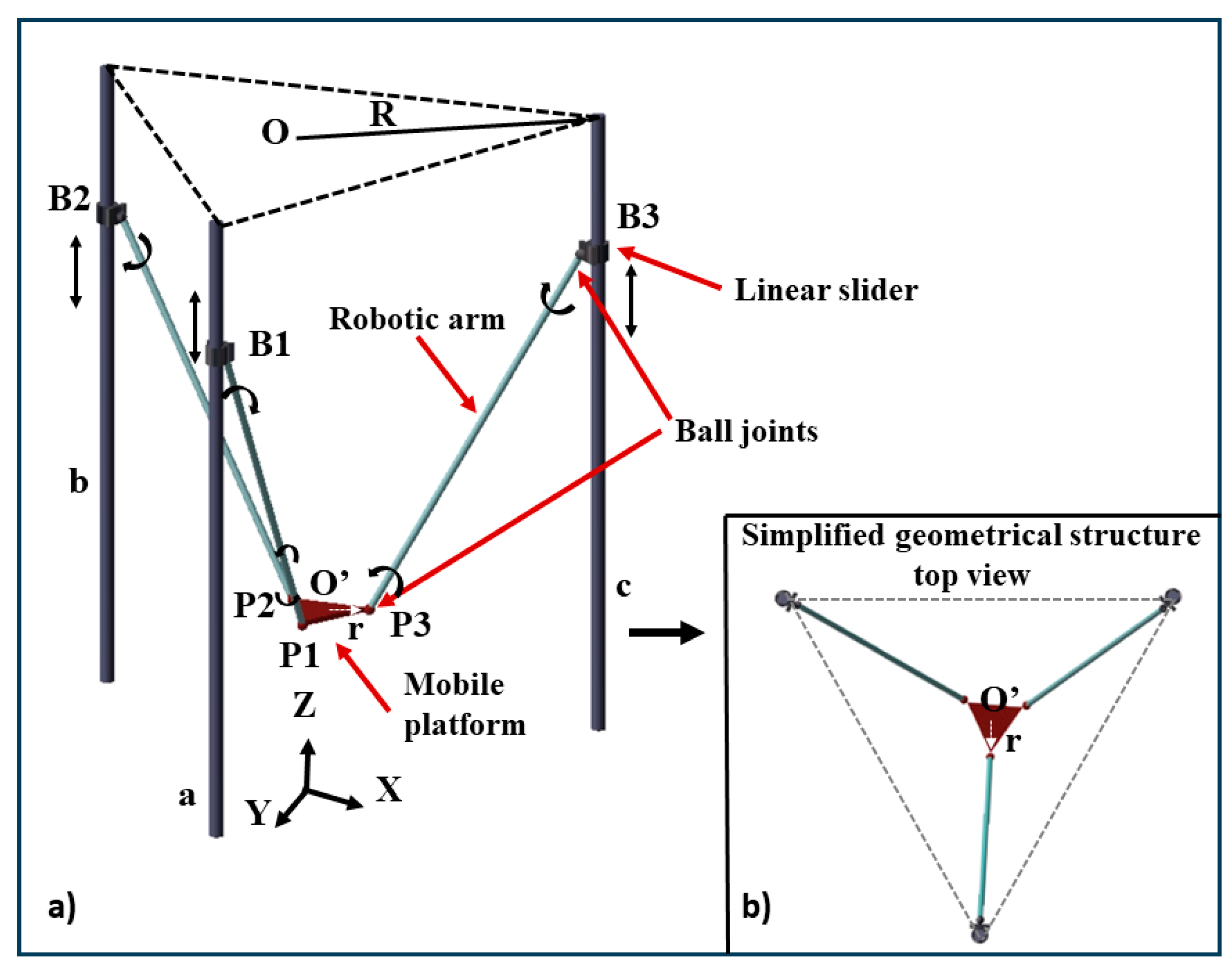
The simplified geometrical model of the linear delta robot design is shown in
Figure 1.
In this design, the ball joints are fixed to the linear sliders (B1, B2, and B3) and the end-effector (P1, P2, and P3). The point in the centre of the mass of the base plane O is (0, 0, 0), the coordinate of the end-effector O’ (
x,
y,
z), and the displacement of the linear sliders are z1, z2, and z3, respectively. This means that the coordinates of the linear sliders B1, B2, and B3 are (0, √3/2, z1), (−√3/2, z2), (√3/2, 0, z3), respectively. The geometrical relationship between the arm length
L, the radius of the base platform
R, and the moving platform radius are obtained using Equations (1)–(4).
Equation (1) shows the spatial relationship between the robotic rods and the centre of the mobile platform using vector arithmetic to express the rod length L.
Equations (2)–(4) are related by the robotic rod length L which is obtained by end-effector coordinates (x, y, z), r, R, and the vertical motion of the 3 linear sliders z1, z2, and z3, respectively. Through mathematical simplifications, the equations of x, y, z or z1, z2, and z3 can be obtained. Please note that Equations (2)–(4) have two possible solutions representing the elbow up/down operation of the end effector. The operation of our robot is limited to the bottom area of the platform (elbow-down operation).
The mathematical equations to express the coordinates of the end-effector were obtained using Equations (5)–(7):
where
Note that the variables A, B, C, and D are the dynamic parameters including the displacement of the linear sliders, the radius of the base platform, and the radius of the end-effector platform (see Abbreviations for the formula symbols and abbreviations). To determine the robot dimensions, the vertical motion limits of the sliders on the lead screws and the real-time coordinates of the end-effector were used.
2.2. Dynamic Robot Performance and Motion Resolution
Using Equations (1)–(8) while defining the motion limits of B1, B2, and B3, the motion state of the end-effector O’ was represented dynamically through simulations. The robot design and the kinematics’ modelling were simulated using MATLAB 2020 (Math Works, Natick, Massachusetts, USA) and CATIA V5-6R2018 (Dassault Systems, Vélizy-Villacoublay, France).
Following the geometric solution of the forward kinematics, our simulation results show that the motion resolution considering the final arm length and the base platform radius (L = 250 mm, R = 235 mm, and r = 20 mm) ranges between 0.24–0.625μm.
Thus, the minimum single-step motion resolution of a single motor is 0.625 μm considering micro-stepping of 1/8.
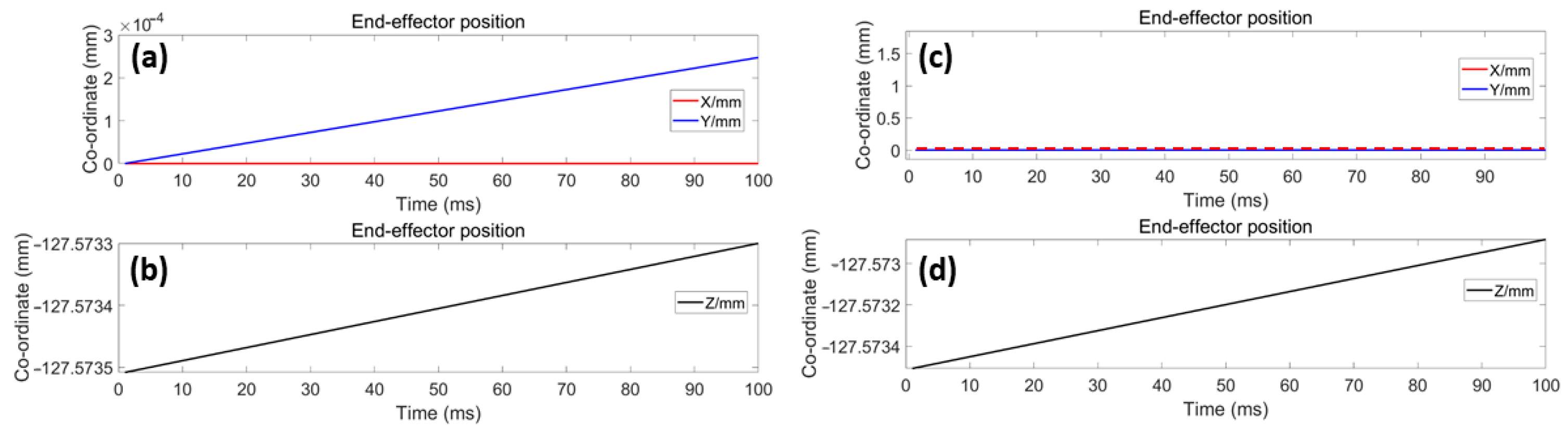
Figure 2 presents an example trace resulting from the simulations outlining the displacement of the end-effector in the X, Y, and Z axes.
Figure 2a shows the displacement of the X and Y axes’ coordinates over time, showing a simulated resolution of 0.24 μm/step when a single actuator is used.
Figure 2b shows the Z axis coordinate displacement over time.
Figure 2c shows the X and Y axes’ motion when the end-effector performs a single vertical movement using the three actuators.
Figure 2d shows the coordinates’ change over time for a Z axis movement reaching a simulated resolution of 0.625 μm/step. From these results, it can be observed that the maximum achieved motion resolution, considering the final dimension parameters, are ~ 0.625 μm under the normal operation of the robot, i.e., when the three actuators are moved simultaneously to displace the end-effector.
2.3. Evaluation of Workspace
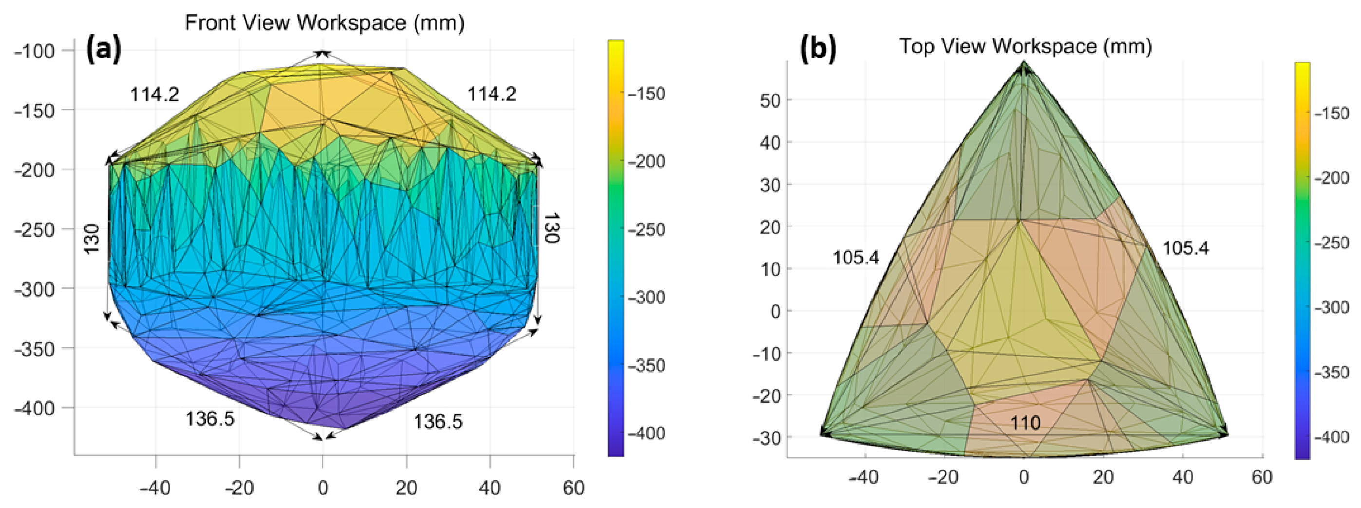
To assess the robot’s workspace considering the obtained dimensions (L, R, and r), all the simulated trajectory points of the end-effector O’ were traced.
Figure 3 shows the front and top view of the simulated workspace having a pyramid-like structure with dimensions of ~114.2 mm × 114.2 mm × 110 mm and 130 mm in depth.
The forward kinematic simulation shows that the end-effector resolution of the linear delta robot can reach a maximum of 0.36 μm/pulse considering 1/8 micro-stepping and 1.75 μm/pulse considering 1/2 micro-stepping. By integrating both the workspace and motion resolution, it can be concluded that using the design parameters obtained (R = 250 mm, L = 235 mm, and r = 20 mm), it is possible to reach the required precision for microsurgical applications dealing with structures having dimensions between 300 to 800 μm [
19,
20].
The inverse kinematic (IK) simulation was used to determine the accuracy of the stepper actuators and to guarantee, through simulations, that the system configuration will achieve the sub-millimetre-level performance required for high-precision applications. The IK expressions are represented in a similar fashion to forward kinematics. Here, the positions B1, B2, and B3 were expressed as the positions of the end-effector (
x,
y,
z). Following the linear delta robot geometrical construction shown in
Figure 1, the coordinates of the linear sliders on the XOY plane were considered to be fixed. Then, the change of the coordinates is reflected in the displacement of the Z axis coordinates relative to the initial position (z1, z2, and z3). The real-time Z axis coordinates of B1, B2, and B3 can be obtained through Equations (9)–(11):
Note that Equations (9)–(11) show the vertical motion of the linear sliders z1, z2, and z3 expressed by the parameters L, R, and r, which are affected by the end-effector’s position (x, y, z) (see Abbreviations for the formula symbols and abbreviations). The notation ± corresponds to the robotic motion’s direction where a positive sign indicates an elbow-down motion of the end-effector’s position.
2.4. Evaluation of the Robot’s Load Capacity
To validate the load capacity of the proposed robotic system, the torque was calculated using the inverse kinematic model developed based on Equations (9)–(11). Equation (12) is used to express the dynamic performance of the robot. The terms in such an equation represent the three indices used for describing the dynamics of the linear delta robot presented in this work. These are M(i), which is the mass matrix, with M representing the load, and V(i), which is the force matrix related to the velocity matrix as described by the velocity model of the ball joints and the inertia matrix of the linear sliders. Finally, G(i) is the potential energy term resulting from the partial derivative of the system’s potential energy with respect to the joint position, which is determined by the load m and the joint’s position.
where
T(
i) represents the torque calculated at motor i.
V is the velocity vector of the end-effector in the X, Y, and Z axes’ direction, and
Vp is the velocity vector of the 3 ball joints (B1, B2, and B3) on the linear sliders.
m is the total weight of the end-effector, considering the assessed load.
J is the Jacobian matrix which is used to define the relationship between the velocity vector of the end-effector and velocity of the joints.
P represents the velocity transfer model consisting of
m, Jacobian, and the inverse of the Jacobian matrix. In our simulation, we defined and inputted the value of the end-effector velocity vector, allowing us to obtain
Vp.
w(
i) represents the angular velocities of the robotic arms connected with the three ball joints (B1, B2, and B3) to the linear sliders obtained from the linear velocity on the robotic arms, which are impacted by the arm length parameters. By defining the value of the load, the torque capacity among the three joints on the linear sliders can be obtained. To calculate the torques, the velocity vector V of the joints and the Jacobian matrix J need to be defined. Equation (13) shows the solution of the Jacobian matrix considering the partial derivative of the end-effector coordinates with respect to dimensional parameters and robotic arm angles [
21], relating the joint velocities to end-effector velocities with both being dependent on the geometric parameters of the robot (see Abbreviations for the formula symbols and abbreviations).
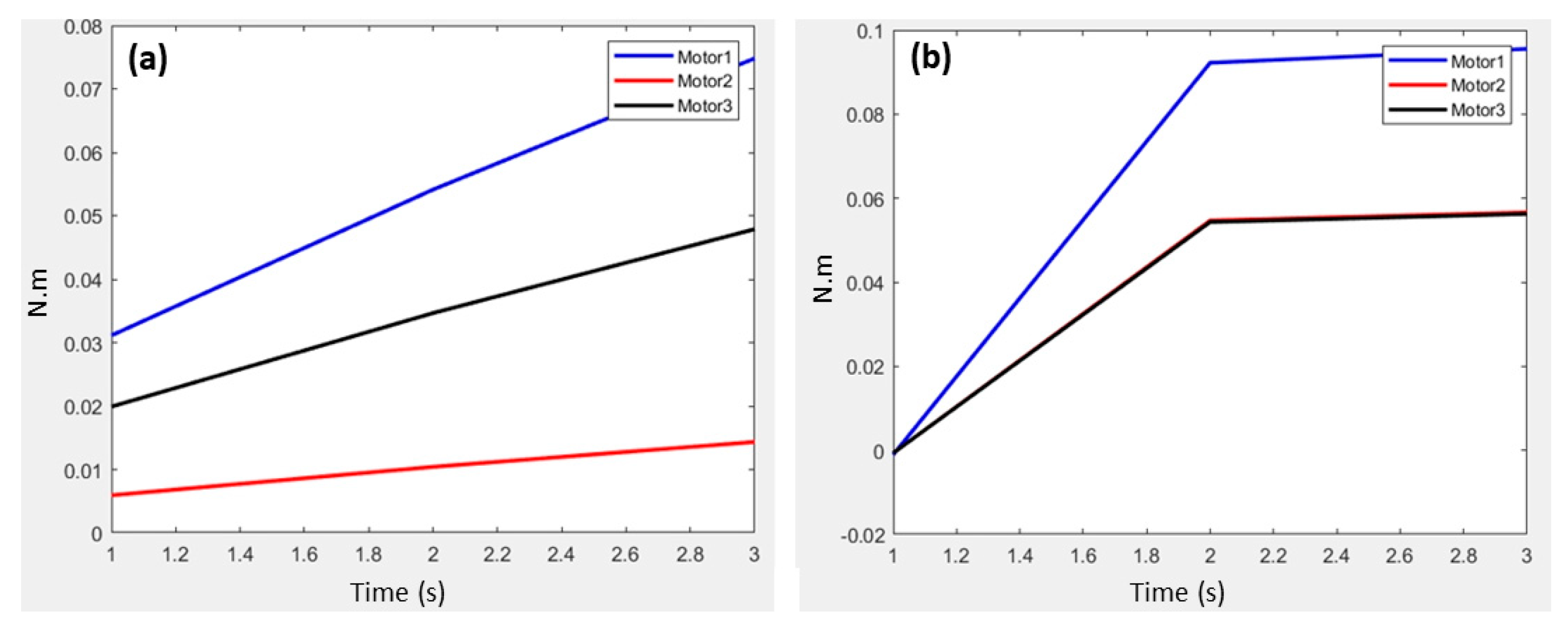
The maximum load of the system can be estimated by considering the torque of a single actuator’s maximum torque specification. As shown in
Figure 4, when the load in each joint is under 2 kg and the end-effector follows a helical trajectory in the XOY plane, the required torque to move such a mass is 0.094 N.m, being less than the actuator-specified torque of 0.12 N.m. Therefore, considering that the three actuators are linked to the end-effector, it can be concluded that this system is capable of handling loads of ~2 kg.
2.5. Robot Construction
The results obtained from the mathematical formulations and kinematic simulations, as presented in the previous sections, were employed to build the robotic system. The description of the full mechatronic design of the linear delta robot considers four building blocks: the linear drive sub-system, the rod–joints assembly, the end-effector, and the control system [
22].
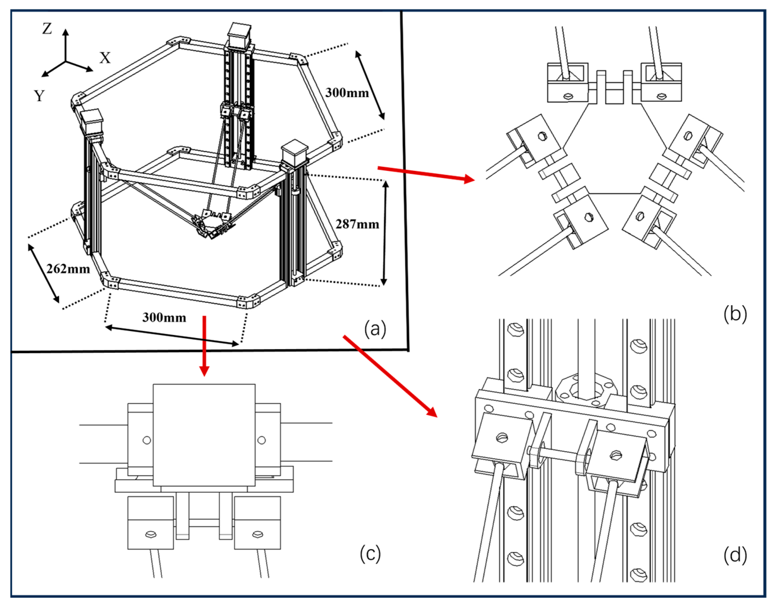
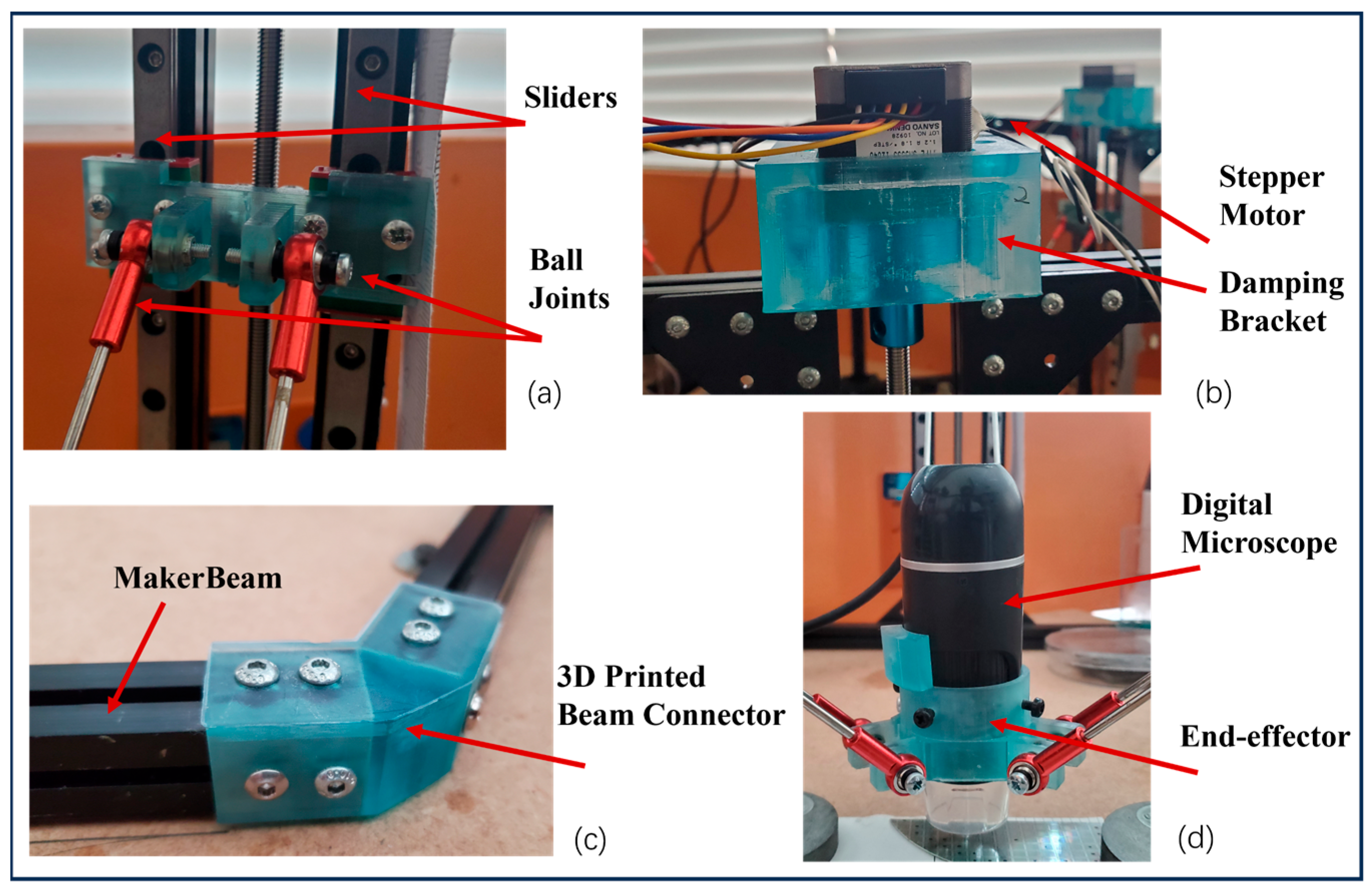
Figure 5 outlines the mechatronic design drawings showing (a) the main assembly and the detailed view of (b) the end-effector, which is connected to the drive system via a pair of parallel rods using 2 ball joints in each side, allowing for rotational movements in the X, Y, and Z axes, (c) the linear drive, composed of the stepper actuators that are fixed on the top of the robot platform having its shaft coupled to the leadscrews, and (d) the rod–joints assembly, connecting the linear guides’ slider to each pair of parallel rods.
The hardware construction was based on extruded aluminium beams (MakerBeam B.V., Utrecht, The Netherland), injection moulded brackets, and sealed chrome steel bearings, which are all commercially available. The robot was assembled through the connection of the extruded aluminium beams using in-house 3D-printed beam connectors and T-Slot nuts. The angular position between the connection of the beams is ensured through the 3D-printed beam connectors’ design, considering a triangular insert with the required angle (see
Figure 6c). The drive system uses three 35 mm SH3533-12U40 unipolar stepper motors (Sanyo Denki, Tokyo, Japan) and three BSD-02.V motor drivers (RTA Pavia, Marcignago, Italy). The stepper motors are connected to the lead screws using generic shaft couplers. The bottom of the lead screw is fixed to the platform using pillow blocks with bore ball bearings (Motion Co., Guilford, UK). Considering the dimensions of the linear guides, the shaft couplers and the pillow blocks result in a slider motion range along the linear guide of ~287 mm.
Each pair of sliders is connected through a 3D-printed block to the lead screws’ brass nuts and the 300 mm linear guides (see
Figure 6a). This assembly is then used to drive the motion of the robotic arms connected to the end-effector via the ball joints, as depicted in
Figure 6d.
The control subsystem was developed using a myRIO 1900 FPGA (National Instruments, Austin, TX, USA) which was programmed using the NI LabVIEW 2019 software.
Figure 6 shows the details of the robot assembly, outlining (a) the rod–joint assembly, (b) the linear drive sub-system, (c) the beam connector with angular stops to ensure the assembly has the angles required between the coupled beams, and (d) the end-effector, provisioned with a digital microscope.
3. Results
In this section, proof-of-concept experiments that assess the performance of the developed high-precision delta robot are presented. Three experimental scenarios were designed to mimic the tasks performed in the fields of microsurgery, electronics, and photonics, all requiring precision levels in the micrometre range.
For the evaluation of the precision and kinematic performance of the robotic system, a digital microscope based on a five-elements objective lens with an equivalent focal length of 15.8 mm (Celestron LLC, Torrance, CA, USA, HHDMP-44308) was used. For the digital microscope, magnification is adjusted through a tube slider by changing the lens distance between the 5 MP camera and the object. The motion resolution tests resulted in precisions of 1.32 ± 0.02 μm for the Z axis and 3.37 ± 0.17 μm for the X and Y axes [
6].
3.1. Microsurgical Resection Test
Operations involving cellular-level precision are essential to various microsurgical procedures, particularly in the field of dermatology and plastic surgery [
16,
19]. Considering the versatility of the developed system, we present an experimental demonstration to evaluate the accuracy of the robot’s operation using a histological section of a fixed mammalian stratified squamous epithelium sample (Phillip Harris, Cheshire, UK, A12579).
The robot trajectory was programmed to simulate a resection procedure where a lesioned region within the tissue is identified and removed.
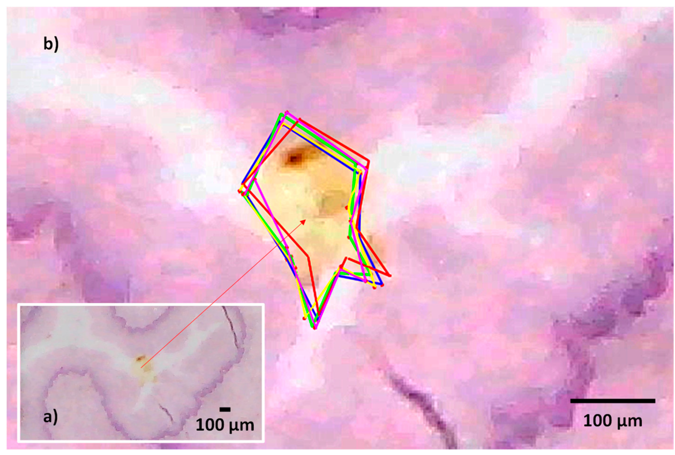
For this purpose, the squamous epithelium sample was visualized with our digital microscope. The sample was analysed to find an incursion (i.e., the lesion) which we aimed to delineate mimicking the resection procedure. The geometry of the incursion was used to set the corresponding motor commands using our custom-made LabVIEW 2019 (National Instruments, Austin, TX, USA) interface. A video of the trajectory was recorded for analysis purposes. The trajectory was repeated five times and displayed in the image.
Figure 7 shows the magnified view provided by the digital microscope of the histological section containing the incursion. Colour coding is used to allow for the identification of each trajectory, as presented in
Figure 7b.
Image analysis was performed using the image J software V 1.54f (Bethesda, MD, USA) to quantify the trajectory errors.
Table 1 shows the results obtained from performing a complex trajectory delimitating the borders of the incursion embedded in the histology sample. It can be observed that when the end-effector moves along a straight trajectory, the resolution was 2.91 ± 0.21 μm, falling within the range of the measured system resolution considering single steps [
6]. However, as expected, angular changes in the trajectory affect producing variations on the obtained resolution. This is observed while executing the trajectory multiple times. The average trajectory errors relate the motion resolution to the relative distance between the actual trajectory of the end-effector and the sample’s perimeter, resulting in an average error of 7.54 ± 1.83 μm, corresponding to a maximum error of 4.7%. This can be further eliminated by fine-tuning the trajectory planning and adding compensation to the control algorithm. Nonetheless, the mutual differences between the five trajectories demonstrate the reliability and repeatability of the robot when performing repetitive tasks.
3.2. High-Precision Tests for Probing a Silicon Wafer
Microchip manufacturing relies on multiple processes based on semiconductors’ material deposition, etching, metallization, etc., to add the different substrates forming the transistors, voltage, and ground planes within a silicon wafer [
23]. This implies that once the fabrication process is finished, hundreds of microchips contained in the wafer are ready for testing. The reduced dimensions require employing test probes with micrometric dimensions to identify the usable microchips while discarding the faulty ones.
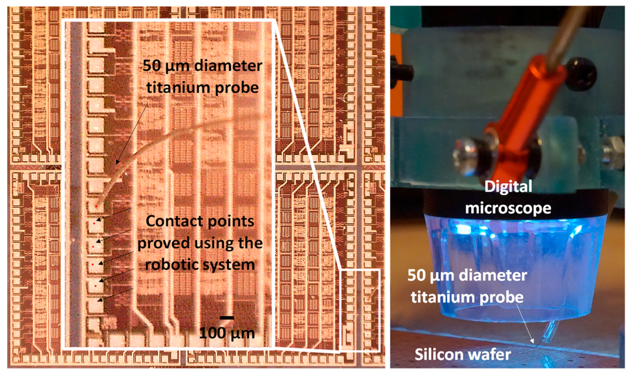
To validate the potential of the ROMI robotic system in the field of microelectronic testing, we developed a custom-made end-effector having both the digital microscopy system and a 50 μm titanium test probe (Goodfellow, Cambridge, UK TI00-WR-000100). The objective of the experiment consisted of defining a trajectory to locate the probe at six ground plane pads of a generic silicon wafer to simulate the probing tasks carried out to identify usable microchips. The experimental evaluation of the robot consisted of describing a linear motion along the direction of the contact pads, stopping at each identified position. The process was repeated five times. A second test was carried out with additional loads of 50 g, 100 g, and 200 g added to the end-effector for mimicking the use of different probes with different weight characteristics.
Figure 8 shows a close-up of the custom-made end-effector provisioned with the digital microscope and the designed titanium probe. The contact points made by the robot are indicated with red dots and black arrows in
Figure 8.
Table 2 shows the results obtained from performing a linear trajectory while making contact with the titanium probe onto the ground plane pads of a microchip contained in a silicon wafer, considering (a) no extra load and (b) the addition of the additional loads to the end-effector. During the experiments, it was observed that when setting the system to work without any additional load, the resolution achieved by the robot was 3.61 ± 0.29 μm/step, being consistent with the experimental robot resolution.
During motion, the end-effector undergoes acceleration, deceleration, and angular changes, impacting its stiffness and, therefore, its precision. This is particularly important whenever the robotic system is operated with different load conditions. In this test, we aimed to assess whether the motion resolution is preserved, confirming that enough torque is delivered by the motor drivers throughout a given end-effector trajectory. This was tested by adding loads of 50 g, 100 g, and 200 g, while performing the same trajectory. The results obtained present variations in the range of hundreds of nanometres when considering single-step motion and compared with the case where no additional load was added to the end-effector. The results are shown in
Table 2.
3.3. Photonic Components’ Alignment Test
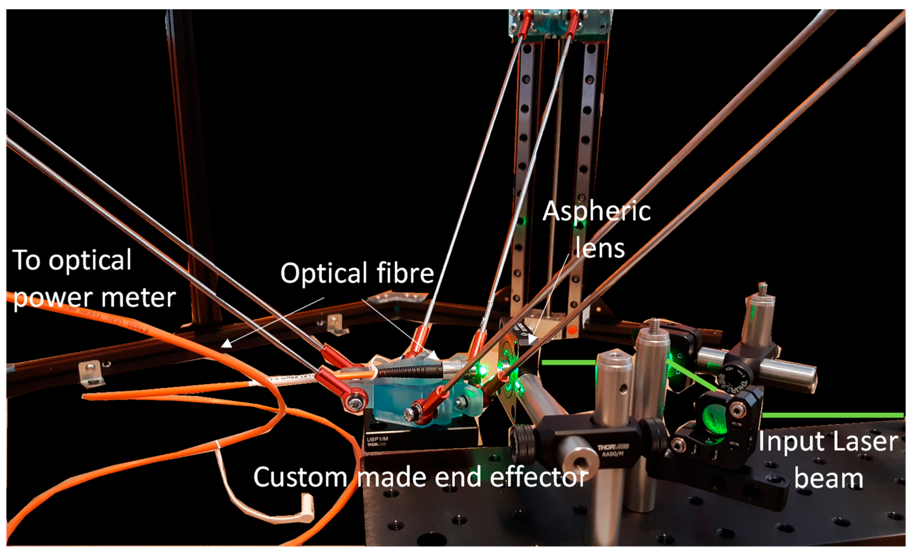
For the photonic components’ alignment test, the robotic system should be capable of achieving the required precision, taking into account the optical components’ dimensional characteristics. The objective of this experiment was to assess its applicability in a scenario where the emission of a laser beam is coupled into an optical fibre. For this purpose, we selected a Ø50 µm, 0.22 NA, Low OH, FC/PC-FC/PC Fibre Patch Cable (Thorlabs, Newton, NJ, USA).
The green emission of a FYLA Iceblink laser (Paterna, Valencia, Spain), selected via an excitation filter (532/18 nm single bandpass filter), was launched towards an aspheric lens with a focal length of 11 mm (Thorlabs, Newton, NJ, USA, C397TMD). This was carried out by using a pair of silver-coated mirrors (Thorlabs, Newton, NJ, USA, PF05-03-P01) mounted in kinematic mounts (Thorlabs, Newton, NJ, USA, MK05/M) to ensure the beam was aligned parallel to the optical bench.
A custom-made end-effector, holding the multimode fibre was designed and 3D-printed to couple the focused laser beam into the optical fibre core. An optical power meter (Thorlabs, Newton, NJ, USA, S405C) was used to obtain initial optical power readings. Upon having a reading at the optical fibre output, initially in the microwatts range, the robotic end-effector was moved iteratively in the X, Y, and Z directions, employing the robots’ single step resolution to maximize the coupling of light. The coupling efficiency calculations were carried out by performing the ratio between the laser output and the coupled light output power coming through the other end of the fibre.
Figure 9 shows the optical system layout used to launch a laser beam towards an aspheric lens. Using the robotic system, a coupling efficiency of 65% was achieved. Although further optimization can be carried out, the coupling efficiency obtained is considered to be enough for the purpose of this proof-of-concept test. This experiment provides evidence of the potential use of our robotic system for high-precision optical tasks’ development, such as multimode optical fibre alignment.
4. Discussion
In this paper, the design process, simulation, and testing of a new high-precision delta robot are described.
We have presented three experimental scenarios outlining the inherent advantages of the designed delta robot when compared to state-of-the-art developments [
9,
10,
14,
15,
17,
24,
25]. These include a simple design capable of achieving high-precision motion resolutions of <5 μm and payloads meeting the weight requirement of industrial and medical applications.
A key point to mention is that the robot, in its current development stage, operates in an open-loop configuration. As expected, this affects the obtained results in the presented experiments, adding repeatable offsets. Upon analysis, these offset errors appeared to be repeatable; therefore, these were reduced by adding a compensation parameter which is included in the custom-made control software performing the trajectory execution.
In the trajectory test, assessing the robot’s accuracy using the stratified squamous epithelium sample resulted in average trajectory errors ranging from 2% to 4.7%, relative to the overall dimensions of the sample. These results are expected given the robots current open-loop operation; nonetheless, the robot was able to achieve a repeatable trajectory within the perimeter of the incursion, demonstrating consistent repeatability when performing complex trajectory tasks. This was achieved by performing systematic compensation in the opposite angle and trajectory direction. An important aspect to be considered is that when performing resection tasks, surgeons require leaving a margin to ensure the complete removal of the lesion. The differences found within trajectories can be considered suitable for microsurgical applications, since the robot already operates below the dimensions of structures manipulated during such interventions with dimensions in the range of 300 to 800 μm.
The second experiment focused on simulating the task of testing microchips within a silicon wafer which exhibited a resolution of 3.61 ± 0.29 μm without any additional load. With increasing loads, the system demonstrated a consistent performance, having an average variation of 470 nm, which may be attributed to the experimental error. Slight trajectory variations can be attributed to the fact that the robotic end-effector is accelerated and decelerated at each contact point, suffering from the characteristic vibrations present in stepper motor technology. This validates the initial considerations made in our simulation and when selecting the robot actuators to manage loads up to 2 kg. These results provide evidence of the robot’s potential for high-precision micromanipulation tasks using end-effectors with different load conditions in electronic applications.
Finally, in the optical fibre-alignment test, the robotic system was assessed for its applicability in coupling the light of a laser beam into a multimode optical fibre. The developed robot was able to successfully position the core of the optical fibre to meet the focused laser beam, achieving a coupling efficiency of 65%. In this experiment, it was crucial to implement the control commands leading the X, Y, and Z trajectories, as any deviation of these would have an impact on the fibre-alignment time and the obtained results.
Table 3 summarizes the representative research of high-precision robots, including key performance parameters such as accuracy, mechanism type, features, and applications. It can be seen that the geometry, based on parallel robots, provides an improved resolution when comparing these with serial robots. Although these robot designs can be used for micro-manipulation tasks, their reduced payload capability and workspace limit its applications in real-world precision tasks.
Table 3 also compares the proposed system with commercial devices originally developed for industrial applications such as ABB’s IRB 360 FlexPicker [
24] and Adept Quattro s650HS [
25], both of which provide sub-millimetre position accuracies at the expense of these being complex and highly priced [
24,
25]. The key advantages of ROMI are that it combines a simple and cost-effective design based on the shelf components delivering an average precision motion of 3.30 ± 0.3 μm while being able to handle payloads of up to 2 kg, both of which are required for real-world applications, such as those presented in this paper.
5. Conclusions
In this paper the design, simulation, and testing of ROMI, a high-precision delta robot, was presented. The robot design was focused on developing a system for high-precision applications. It considers the drawbacks of state-of-the-art robot implementations, addressing the needs for eliminating the complexity of other high-precision robot implementations, as well as achieving a workspace with dimensions in the range of hundreds of millimetres, a target motion precision of <5 μm, and load capabilities of up to 2 kg, all of which are required for high-precision industrial and medical tasks. The obtained simulation results allowed us to validate the proposed design for its construction and testing. An evaluation of the system was carried out through the development of proof-of-concept tests mimicking tasks developed in the areas of microsurgery, semiconductor inspection, and photonic elements’ alignment. Throughout the tests, the versatility of the robot was demonstrated, showing that our system can achieve an average resolution of ~3.30 ± 0.3 μm, even with varying load conditions. As expected, given that the robot operates in an open-loop configuration, in all the experiments, the motion trajectories had repeatable offsets, which were compensated for through the control software.
The application of our design for healthcare applications was demonstrated by mimicking the task of lesion excisions during microsurgery, showing its capabilities to delineate the perimeter of micron-sized incursions in a histological sample. The path described by the robot with that of the actual sample region of interest were used to determine the error obtained, which resulted in an average value of 7.54 ± 1.83 μm, corresponding to a maximum error of 4.7%, relative to the overall dimensions of the specimen. This, however, does not impact the execution of a microsurgical task, given that resections require leaving a margin between the damaged and healthy structures for ensuring the complete removal of these. Probing a silicon wafer is carried out through expensive and complex robotic systems. In this paper, the results provide evidence that our robotic system can be used to manipulate test probes with a sufficient resolution to target the contact pads (with dimensions in the range of 100 μm) of a microchip contained in a silicon wafer. Similarly, the device was customized for testing its suitability to develop high-precision photonic tasks. The optical coupling of a laser beam was carried out into a multimode fiber having a core diameter of 50 μm. By displacing the robotic end-effector in the X, Y, and Z directions iteratively and by employing the robots’ single-step resolution, a coupling efficiency of 65% was achieved. These results demonstrate the potential application of the design methodology presented in this paper to develop robotic systems for high-precision tasks in industrial and healthcare settings.
Future work will be focused on implementing a closed-loop operation considering optical encoders or a visual serving approach to further reduce the errors present when operating the robot. We will also explore the effect of the geometric errors resulting from the robot’s manufacturing, considering its tolerances [
1,
8]. This will contribute to achieving higher stability and motion precision when the robot is used for high-precision tasks.


