Article

5G on the Farm: Evaluating Wireless Network Capabilities and Needs for Agricultural Robotics

1
Lincoln Institute for Agri-Food Technology, University of Lincoln, Lincoln LN6 7TS, UK
2
Global Smart Transformation Ltd., Inverurie AB51 0BT, UK
*
Author to whom correspondence should be addressed.
Machines 2023, 11(12), 1064; https://doi.org/10.3390/machines11121064
Submission received: 26 October 2023 / Revised: 20 November 2023 / Accepted: 24 November 2023 / Published: 30 November 2023
(This article belongs to the Special Issue New Trends in Robotics, Automation and Mechatronics)

Abstract

:
Global food security is a critical issue today, strained by a wide range of factors including global warming, carbon emissions, sociopolitical and economic challenges, traditional workforce decline and population growth. Technical innovations that address food security, like agricultural robotics, are gaining traction in industry settings, moving from controlled labs and experimental test facilities to real-world environments. Such technologies require sufficient network infrastructure to support in-field operations; thus, there is increased urgency to establish reliable, high-speed wireless communication networking solutions that enable deployment of autonomous agri-robots. The work presented here includes two contributions at the intersection of network infrastructure and in-field agricultural robotics. First, the physical performance of a private 5G-SA system in an agri-robotics application is evaluated and in-field experimental results are presented. These results are compared (using the same experimental setup) against public 4G and private WiFi6 (a newly emerging wireless communication standard). Second, a simulated experiment was performed to assess the “real-time” operational delay in critical tasks that may require quick turnaround between in-field robot and off-board processing. The results demonstrate that public 4G cannot be used in the agricultural domain for applications that require high throughput and reliable communication; that private 5G-SA greatly outperforms public 4G in all performance metrics (as expected); and that private WiFi6, though limited in range, is a fast and very reliable alternative in specific settings. While a single wireless solution does not currently exist for the agricultural domain, multiple technologies can be combined in a hybrid solution that meets the communications requirements.

1. Introduction

The agricultural domain is currently experiencing increased focus on emerging technologies and robotic applications, largely due to concerns about food security and response to climate change. One of the primary motivators for sustainable farming is population growth [1]: current agricultural practises are not sustainable and are not viable for upscaling to secure food for the predicted 10.2 billion people by 2050 [2]. As a result, the intersection of agricultural robotics (or agri-robotics) and supporting technologies, like telecommunications, has garnered international attention from governments and industries alike [3,4,5,6,7]. The work presented here explores the intersection of network infrastructure and in-field agricultural robotics, investigating practical factors that impact our ability to enable state-of-the-art telecommunications networks in farm settings.
First, to motivate our work, we highlight some of the sociopolitical and environmental factors that are having negative impact on global food security and inspiring the recent boom in agricultural robotics. One example where sociopolitical events have stressed the food supply chain is the current war between Russia and Ukraine. These two countries are estimated to account for 30% of the global wheat supply [8,9]. Another example is Brexit, where the UK leaving the EU single market has led to fewer seasonal workers entering the UK, traditionally from Eastern Europe, to support the harvesting of fruits and vegetables [10]. Further, the COVID-19 pandemic laid bare the impact of labour shortages on agricultural productivity in multiple countries [11,12].
Examples of environmental effects on agriculture go both ways: climate change negatively impacts growing conditions and some farming practices negatively impact natural resources. Climate change causes unpredictable weather patterns (e.g., rainfall, heatwaves, average temperatures), which contributes to increased prevalence of weeds, infestations of pests and soil erosion, all of which can stress and damage crops [1,13,14]. And, certain agricultural practices can damage the environment, such as heavy farm vehicles causing soil compaction [15,16] or livestock accounting for a significant percentage of greenhouse gas (GHG) emissions [17].
Precision agriculture [18,19] encompasses a broad spectrum of intelligent technologies that allow growers to make decisions at the level of an individual plant, or group of contiguous plants, rather than an entire field. This means that resources, such as fertilisers and water, as well as herbicides and pesticides, can be targeted to specific plants or planted regions, rather than applying across an entire field, which can be wasteful when only a portion of the field requires that treatment, as well as unnecessarily expensive and potentially damaging to the environment. Intelligent sensors, either mounted in static locations around fields or on mobile devices such as ground-based or aerial (UAV) robots, can feed precise location-specific information about plant growth (e.g., size, colour, shape) and the environment (e.g., temperature, moisture, humidity) to farmers, who can use those data to inform their timetables concerning when (or not) to spray, when to harvest, etc. In addition, specialised actuators can also be mounted on robots to allow the location-specific information to feed real-time decision making and trigger actuation such as spraying, mechanical weeding or harvesting, performed by robots in the field.
From the intelligent robotics perspective, these types of tasks require a number of capabilities: (a) precise location of sensed information; (b) precise location for actuation; (c) path planning for ground-based robots to minimise soil compaction and energy usage or flight planning for aerial robots to minimise energy usage; and (d) accurate analysis of sensed data. The joint desire for highly accurate position information and the ability to transmit sensor data from fields to farmers (or automated decision support systems) highlights the need for communications networks that can deliver both of these capabilities reliably and robustly, and leads us to consider fifth-generation, or 5G, solutions.
Fifth-generation telecommunications is anticipated to provide three key technical advantages over existing fourth-generation capabilities [20]: enhanced mobile broadband (eMBB) at high bandwidth, ultra-reliable low-latency (URLLC) and massive machine-type communications (mMTC) at low bandwidth and high scale to enable Internet-of-Things (IoT) and similar capabilities [21]. Taken together, eMBB and URLLC promise better performance for applications such as accurate and timely positioning and faster sensor data transmission. However, 5G is not available everywhere, and public installations, especially in rural communities where populations are sparse (i.e., the paying customer base is small), are not a high priority in many countries. Thus, we are concerned with understanding the specific practical advantages of private 5G within an agriculture application domain.
In the work presented here, we explore three wireless network technologies and evaluate their performance in an in-field agri-robotics environment. There is one common requirement for all agricultural robots: the need for a reliable, high-throughput and low-latency network connection between robots and operations control. This could be for image recognition on the edge (edge compute), firmware updates, data offload, model training or manual remote assistance. As such, we have chosen to investigate three technologies that can support such intensive operations:
  • 5G has many desirable traits that can be leveraged by farmers that employ such technology, for example, high throughput, low latency and robust communications. Fifth-generation telecommunications can deal with the demands of real-time, in-field image recognition tasks. If farmers were to own their own private 5G, they could also have the opportunity to lease their wireless network capacity when their demand is low or they have unused bandwidth.
  • WiFi6 is soon to become one of the new wireless network standards that will be widely used in appropriate settings (e.g., indoor locations, such as offices and greenhouses). It has impressively high throughput, low latency and more advanced reliability and quality-of-service features than today’s WiFi standard, i.e., WiFi5. The range of WiFi6 is smaller than that of 4G or 5G; hence, a number of mesh solutions have been proposed.
  • 4G is currently available in over 85% of locations worldwide and is anticipated to cover 98% of the globe by 2028 [22]. Fourth-generation telecommunications can theoretically support high throughput and is known to be reliable, but not known to support low latency.
In the work presented here, more emphasis is placed on private 5G and WiFi6, as these are new and emerging communication networks, whereas we consider public 4G as our baseline. A definite advantage of a private system (over public provision) is that the network operator has control over system parameters, albeit within the constraints of their (usually government-regulated) operating license.
Here, we describe and present the results for two separate experiments that we have conducted: a physical experiment to demonstrate capabilities and a simulated experiment to demonstrate requirements. The physical experiment tests the application of two-way communication between an in-field robot streaming real-time video to a remote server, which performs detection of crops and weeds from the received video. The received video stream is converted to a stream of images that are passed on to an AI-driven detection system. The wireless network results for throughput and latency are compared. The simulated experiment uses the average latency results from the physical experiment to compare “real-time” operational performance.
The remainder of this paper is comprised of a literature review (Section 2), exploring current research and state of the art; a description of our methodology and testing environment (Section 3), discussing the three wireless networks and locations where our experiments were conducted; presentation of our physical experiment (Section 4), analysing capabilities through network throughput and latency metrics; discussion of our simulated experiment (Section 5), investigating the requirements for “real-time” operation and control; and finally, a conclusion (Section 6).

2. Related Work

Agricultural environments hold many challenges for wireless networks, as they are unstructured and have natural obstacles that cannot be penetrated by most forms of telecommunications. Alternatively, laying wired infrastructure around farms is even more challenging and expensive [23]. Because of the shear sizes and remote locations of farms, it is unrealistic to dig trenches or erect overhead structures and permanently place wiring or optical cables to provide communication across fields. Such infrastructure could be damaged by normal farm use: farmers are prone to dig up land occasionally, which might damage underground cables, and heavy farm vehicles can cause soil compaction, especially in wet conditions, as much as 25–50 cm deep, which can move or harm underground cables. Fibre optic cables are usually placed 15–20 cm underground and can be laid much deeper, but with a significant increase in cost. Instead, smaller 5G cells can be used to deliver high-speed and reliable wireless communication to rural areas [7]. Currently, the cost of 5G carrier and user equipment remains prohibitively high for private purchase, and such an expanse of public 5G is yet to arrive in rural areas.
From all the challenges that come with wired infrastructure, it is no wonder that the literature in communication and networking for agriculture is mainly focused on wireless networks, Internet-of-Things (IoT) and low-cost and low-power sensors [24,25,26]. The research looks at either multiple sensors on a single device (system-on-chip), performing a specific function, or cloud/fog computing for data collection [27,28,29]. WiFi [27] and Hybrid WiFi/Zigbee [29] communication infrastructures have been investigated, but are limited in functionality and device support, as well as number of communicating devices. Little consideration is given to a more practical and permanent communication infrastructure supporting a wide range of devices, functionalities and robot operations in agricultural environments. However, 5G has the potential to support not only a large number of connected devices, but also a wide range of different devices [6]. Moreover, considering the growth and popularity of 3G and 4G as use cases, the number of devices that support 5G will continue to grow as the technology matures, bringing cheaper and lower-power devices to the market. The lack of such research has been noted with the emergence of 5G [7,30].
The literature in robotics for agriculture shows that the right research questions are being investigated; however, progress is much slower than expected. A divide can be seen between emerging robot applications in other domains such as warehouse robotics and self-driving autonomous vehicles, which employ state-of-the-art research in planning, navigation, environment interaction and machine vision. Comparatively, application of these methodologies in agri-robotics is progressing more slowly, largely due to the more variable and challenging environmental conditions for deployment. High-end industrial tractors with RTK-GPS (real-time kinematic positioning GPS) with basic autopilot and mission planner software features [31] are one example of agri-robotics research that has been demonstrated in the field [32]. Other examples of agri-robotics research making gains include the use of image detection and machine learning in the field [33,34], novel fleet-management and navigation in robot teams [35], and learning from demonstration to scale autonomous navigation [36]. These activities motivate the need for superior telecommunications infrastructure and innovation in rural environments.
Tang et al. [7] present use cases and similar research to draw a hypothetical argument for the use of 5G in agriculture and review outcomes based on expectations. But no actual results are shown of 5G-SA (stand alone) in an agricultural application, which is the contribution we present here. To the best of our knowledge, no research exists in the agricultural domain that evaluates and discusses the practical performance of 5G and compares general wireless technology in a rural environment with detailed performance metrics obtained with robots in the field. Here, we present practical results from a physical experiment performed in two different fields, detailed in Section 4, to demonstrate the physical capabilities of (private) 5G in a messy, real-world setting. In addition, we present simulated results, described in Section 5, to demonstrate the performance requirements for wireless communications in an agri-robotic task environment.

3. Experiment Design

This section describes the underpinning agri-robotics use case that serves as the basis for the experiments presented here (Section 3.1), the image detection methodology we implemented for weed identification (Section 3.2), the locations where experiments were conducted (Section 3.3), the apparatus deployed (Section 3.4), the wireless network systems evaluated (Section 3.5), and finally, how tunnelling was used to support two-way 5G communication (Section 3.6).

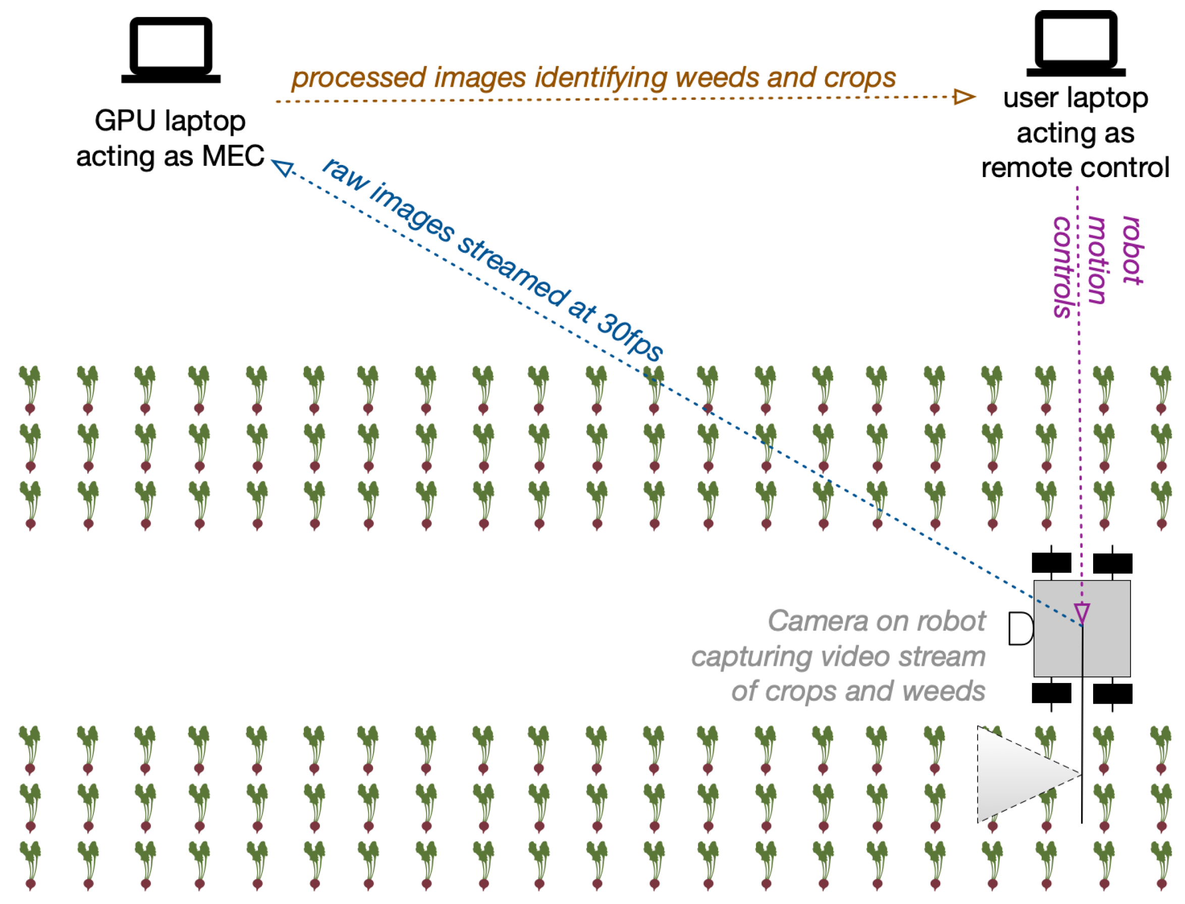
3.1. Agri-Robotics Use Case

The agri-robotics use case we employ for the experiments presented here aims to develop a sprayer robot that can autonomously drive in a farm field performing real-time weed detection and spot spraying [37]. This includes streaming real-time video captured by the robot in the field to an off-board processor for weed detection, followed by transmitting weed locations back to the robot for guiding spraying actuation. The experimental results and discussion in Section 4 evaluate the performance of three different wireless network technologies in performing this task, to demonstrate the capabilities possible with private 5G in comparison with other technologies available. This basic setup can also be used for a range of other applications—not only spot spraying for weeds, but also for spraying pesticides and fungicides, as well as spot irrigation and selective harvesting.
The conceptual setup of our experimental system is shown in Figure 1. Wireless communication was established between a remote-controlled robot driving in a field, streaming video to a laptop with a dedicated GPU acting as a pseudo mobile edge computer (MEC) (see Section 3.4), which in turn performed image analysis in real time and displayed the results on a screen. For collecting our experimental data—where only generic navigation was important and actual spraying did not take place—the remote-controlled robot was a small mobile platform (Leo Rover [38]), outfitted with a small footprint laptop (running Ubuntu Linxu) and a RealSense depth camera [39] The visualisation was adopted for experimental purposes—in a real spraying operation, position information to guide spraying actuation would be sent back to the robot. Sample detection results are shown in Figure 2. The MEC/GPU laptop was placed at a fixed location, depending on the type of wireless network being tested, as described in Section 3.5.

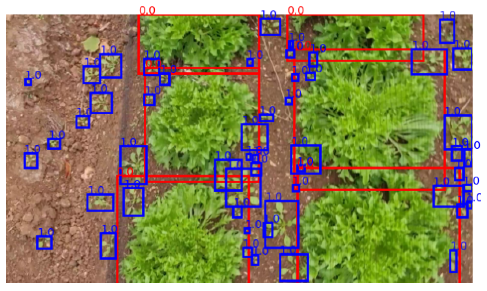
3.2. Image Detection

In related work [37], we developed a Machine Learning (ML) model designed to meet specific image resolution, processing speed and detection accuracy requirements:
  • To detect weeds accurately using this model, images must be in focus and with a resolution of at least 640 × 360 pixels ( width × height ). The ML model benefits from higher resolution images as more detail is retained.
  • To achieve “real-time” performance, the image-processing pipeline (including image capture and object detection) must be capable of running faster than a video stream of 30 frames per second (FPS) or higher (i.e., ≤ 33.3 ms per frame). This is to enable video footage to run uninterrupted at 30FPS with overhead for missed frames.
  • To provide practical utility for the spot-spraying task at hand, the model needs to achieve >80% accuracy in crop vs. weed detection.
In this work [37], seven different ML models were compared and, of those, Yolov5m [40] achieved the best results, with an accuracy of over 87% and image inference at a rate of ~69FPS.
For the experiments described here, Yolov5m was set up on the MEC and the robot streamed video images of the field at 30FPS to the MEC/GPU laptop. The MEC/GPU laptop then analysed the incoming video stream, performed image inference using the learned model, created bounding boxes outlining the crops and weeds in each image, and finally transmitted a live video feed with the detected weeds and crops to the user laptop. Figure 2 illustrates sample results running this model on images of lettuce and surrounding weeds in the field.

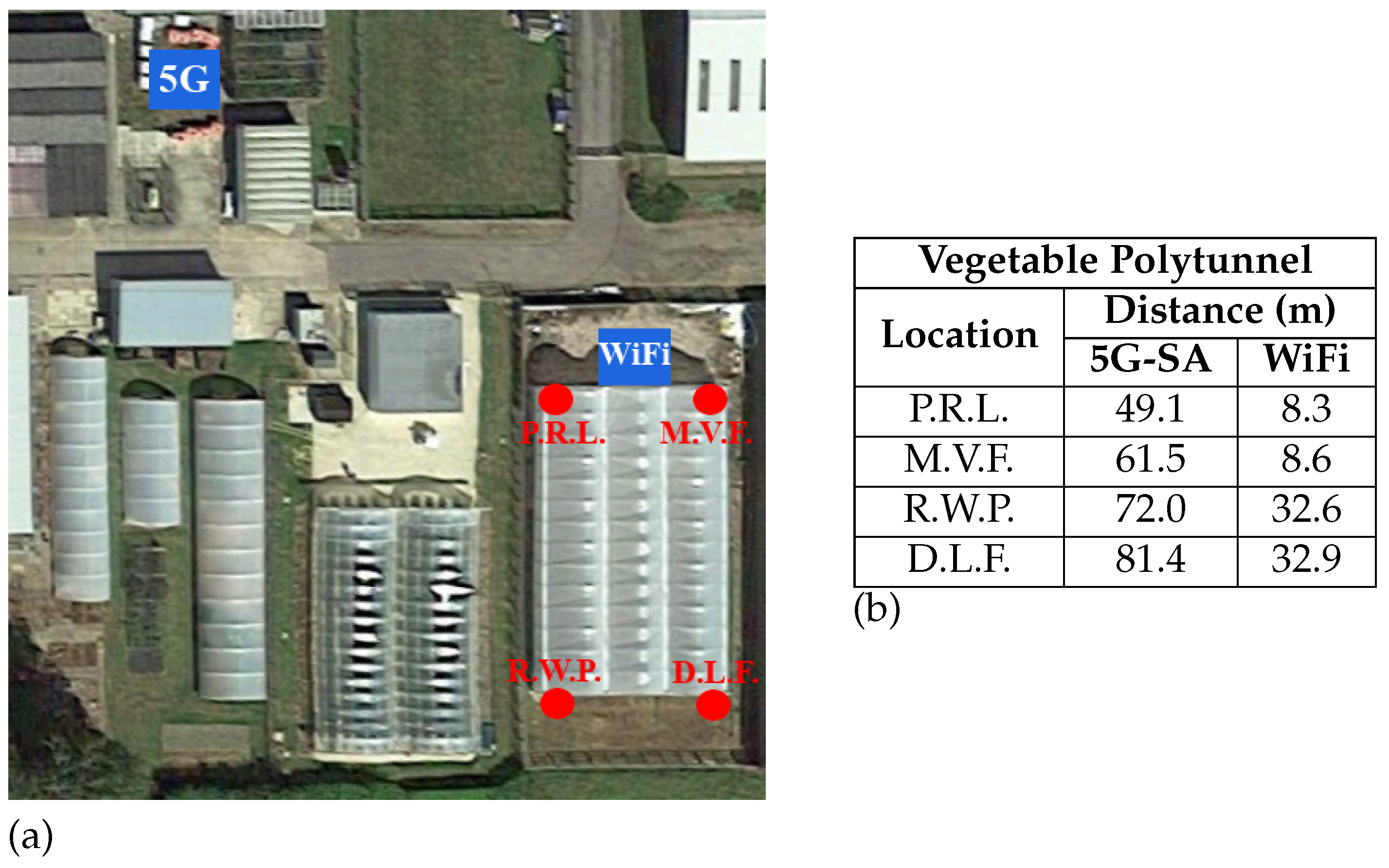
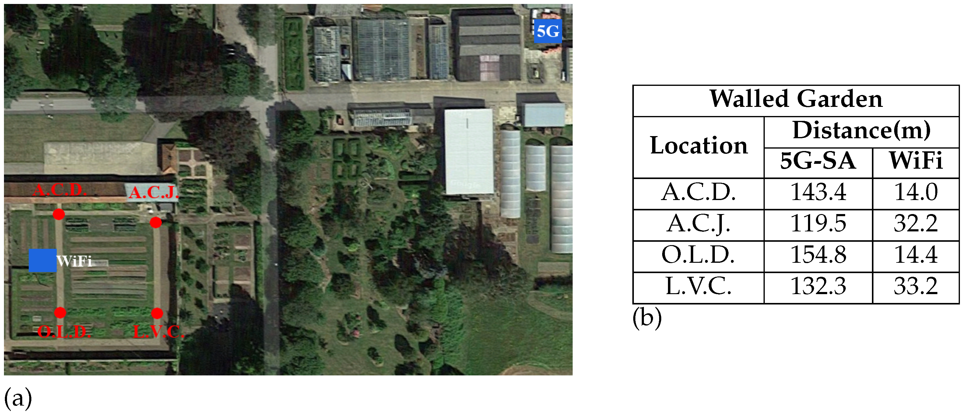
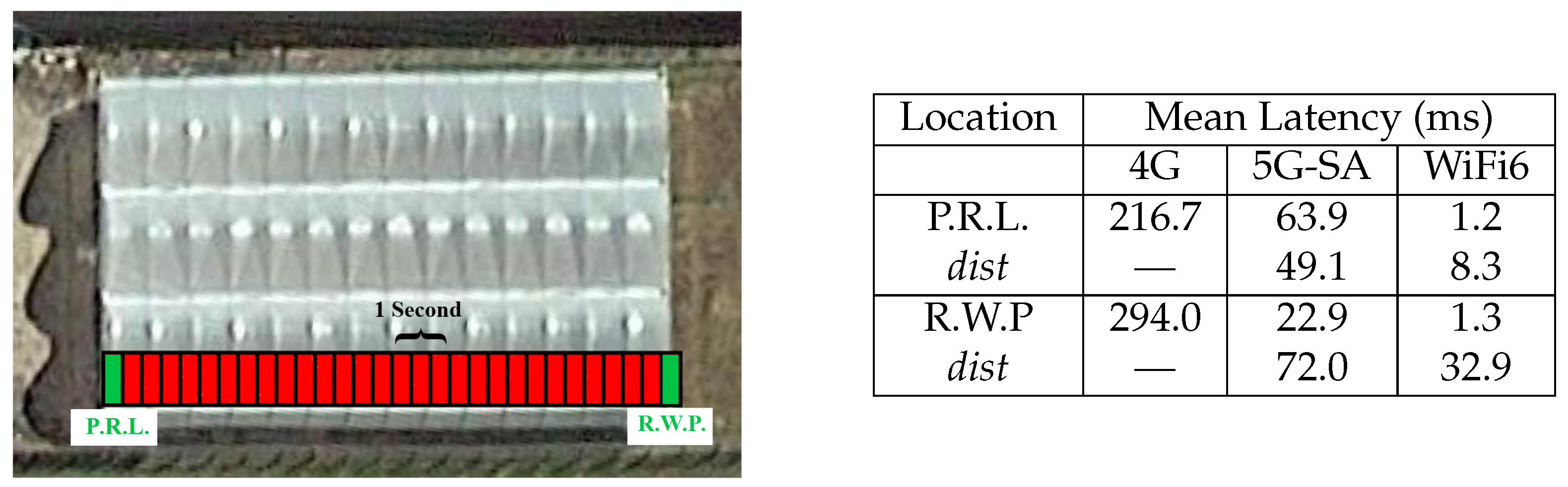
3.3. Experiment Locations

For the results presented here, experiments were conducted in two fields, which we refer to as the Vegetable Polytunnel and the Walled Garden. Our private 5G network has a geographical advantage in the Vegetable Polytunnel compared to the Walled Garden. The Vegetable Polytunnel area has VLoS (visual line-of-sight) with few obstacles blocking the signal and data collection points are at approximate distances of 46 and 80 m to the antenna, the closest and furthest points measured, respectively. In contrast, the Walled Garden is important in testing the limitations of the 5G network because it contains regions with NVLoS (no visual line-of-sight), which are either lightly or heavily obscured by a high tree line and a brick wall surrounding the field. Data collection points in the Walled Garden are at approximate distances of 122 and 154 m, the closest and furthest points measured, respectively. The two areas used for experiments are illustrated in Figure 3 and Figure 4, in Section 4. The areas of operation and exact distances between data collection points, i.e., from network access point (location of MEC/GPU laptop) to in-field robot, are given in Section 4.

3.4. Apparatus

The setup of each of the three communications networks compared in this paper are detailed here. Our 5G system is a stand-alone (SA) network, using the emerging New Radio (NR) sub-6 GHz band N77, which is privately owned by our research facility, making it easier to conduct controlled experiments and with fewer restrictions than a public network. We are able to adjust certain system parameters, within the constraints of our license agreement, in order to support different types of experimentation. WiFi, and by extension WiFi6, can be set up as either a private or public network, as it is not currently (in many countries) controlled by a regulatory body that requires a license to operate. In the experiments reported here, WiFi6 with the 802.11 ax standard was deployed and set up as a private network. The 4G network in these experiments is commonly used: a commercial, publicly available telecommunications system, with no parameters controlled by end users. The wireless networks’ configuration details and common parameters are discussed further in Section 3.5.
Our 5G-SA system currently does not employ a permanent mobile edge compute (MEC) node, which is typically a powerful server-grade system that is used to perform fast computation on the “edge” (i.e., in the local environment) as opposed to sending data off to the “cloud”. In our setup, the server-grade MEC functionality is approximated by a temporary solution, a powerful GPU-driven laptop, which we refer to as our pseudo-MEC, or the MEC/GPU laptop.
All experiments were conducted using two laptops that have identical hardware and adequate compute power. The laptops are deemed to have “adequate” processing power if they have a dedicated GPU with at least 4 GB or more of graphics RAM. Each laptop is an ASUS TUF Dash F15 [41], with i7 11370H @4.8GHz (4 core, 8 thread) CPU, RTX 3060 GPU with 6 GB GDDR6 and 8 GB DDR4 RAM. One laptop was used as the remote server, denoted as the pseudo-MEC, and the other acted as a mobile client integrated on a remote-controlled robot in the field.

3.5. Wireless Networks

The network equipment, including the two laptops used for communication experiments, had different setups depending on the type of network being tested. We tried to keep the setups as similar as possible so that our comparisons of experimental results are valid. This section describes our three different network setups and configurations.

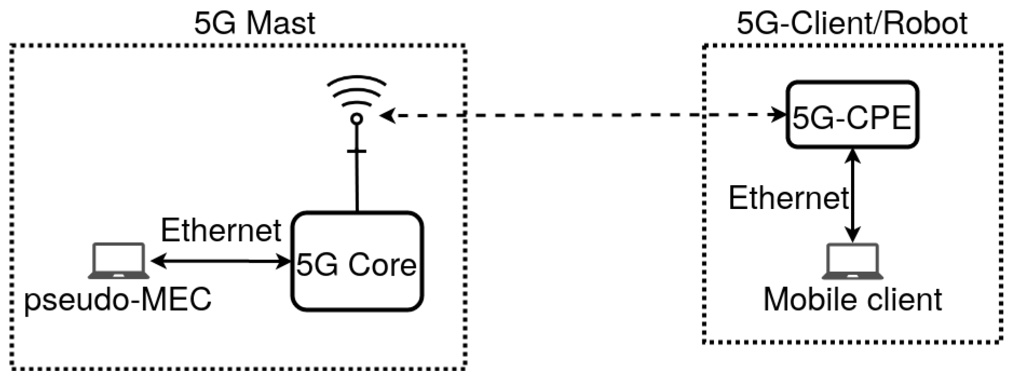
3.5.1. 5G-SA Network

A connection diagram is illustrated in Figure 5. The pseudo-MEC, for the 5G-SA network experiments is directly attached via Ethernet cable (cat6) to the receiving private 5G-SA mast. Moreover, all Ethernet wired cable connections use cat6 cabling, unless otherwise specified. The robot (i.e., mobile client) is connected via an external 5G CPE (Customer-Premises Equipment) device, by Ethernet cable, to allow it to communicate with the 5G-SA network. The 5G-CPE is a router using a pre-configured 5G SIM card, provided by BT [42] and Nokia [43] and configured especially for our private network.
The 5G-SA network (N77) configuration is listed in Table 1, specifying relevant network and system and relevant parameters. There are certain configuration limitations and the metrics listed in the table illustrate what our system is capable of achieving at the time of writing this paper. For example, currently the Time Division Duplex (TDD) and carrier bandwidth are fixed and subject (in the UK) to Ofcom [44] licensing limitations. Download (DL) and upload (UL) speeds are used typically to denote throughput rates or refer to modulation.

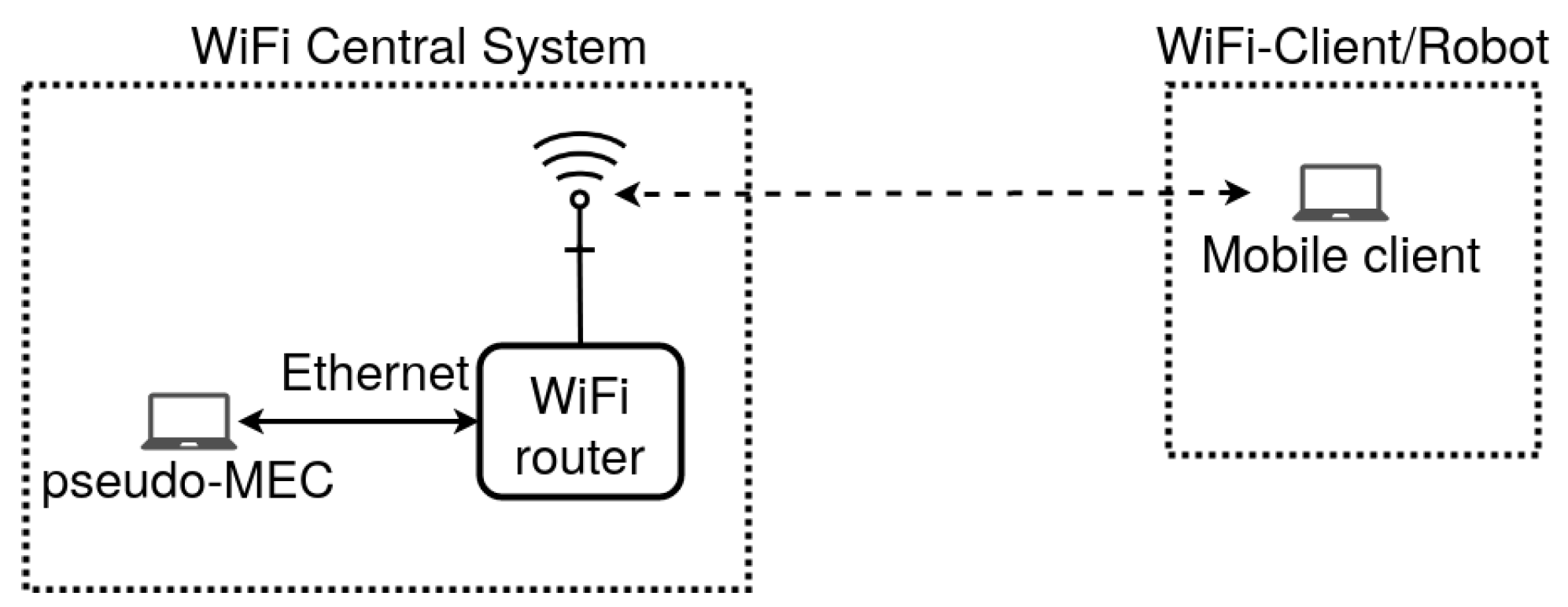
3.5.2. WiFi6 Network

A connection diagram is illustrated in Figure 6. The pseudo-MEC (MEC/GPU laptop) for the WiFi6 network experiments is connected via Ethernet cable (cat6) to a WiFi6 enabled router. The robot’s on-board processor (i.e., the mobile client) has an internal WiFi6 network card that allows it to communicate with the WiFi6 enabled router.
The WiFi6 configuration, specifying relevant network and system parameters, are listed in Table 2. Further details on the specific WiFi6 router used can be found on the manufacturer’s web site [45]. It should be noted that TDD is not a feature of WiFi communication networks and QoS (Quality of Service) groups are disabled (unassigned). For the ideal case (highest throughput and lowest latency), the QoS feature is left disabled.

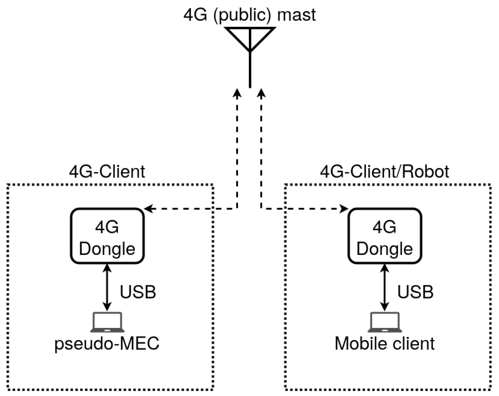
3.5.3. Fourth-Generation Network

Because we used a public 4G network, the MEC/GPU laptop could not be directly connected to a receiving 4G mast. Instead, “mobile client” analogy for the MEC/GPU and robot laptops for the 4G experiments are replaced by client-to-client functionality (see Section 3.6), illustrated in Figure 7. Both mobile clients used for our 4G network experiments connect to the network via external USB dongle devices. The external device used for 4G networking is the D-Link DWM-222 dongle [46].
The 4G configuration, specifying network and system parameters, are estimated in Table 3. The D-Link DWM-222 supports any UK commercial SIM card network carrier and connects to any device via USB2.0 connection. The maximum data rate of USB2.0 is 480 Mbps, which is enough to test the maximum theoretical speed of 4G communication, which is 300 Mbps DL and 150 Mbps UL. However, actual 4G commercial download and upload speed is approximately 6% (18.4 Mbps) and 10% (14.7 Mbps) of the theoretical maximums (achieved by EE [47], respectively. The UL/DL data are aggregated from over 210,000 mobile phones across the UK [48].
To demonstrate the maximum real-world 4G speed achieved in VLoS and within approximately 10 m of a 4G mast, measurements were taken in London (UK) using Ookla [50], which is a speed test application that downloads and uploads a short burst of data to measure throughput; results were 100 Mbps DL and 20 Mbps UL. In a normal usage scenario, it is extremely unlikely to achieve such 4G speeds, as this would require a user to be in close proximity, in VLoS and able to predict low network traffic load for a particular public 4G mast, and additionally to know if the access point for the service they want to use is spatially close (fewer hops between network nodes to reach the server) and that it employs state-of-the-art network capabilities.
Table 3 lists all the known parameters for the 4G network. It should be noted that the actual TDD ratio is unknown and usually dynamic depending on the 4G network carrier. However, the maximum theoretical speeds and real-world practical speeds are well known and documented for 4G; these are given in Table 3.

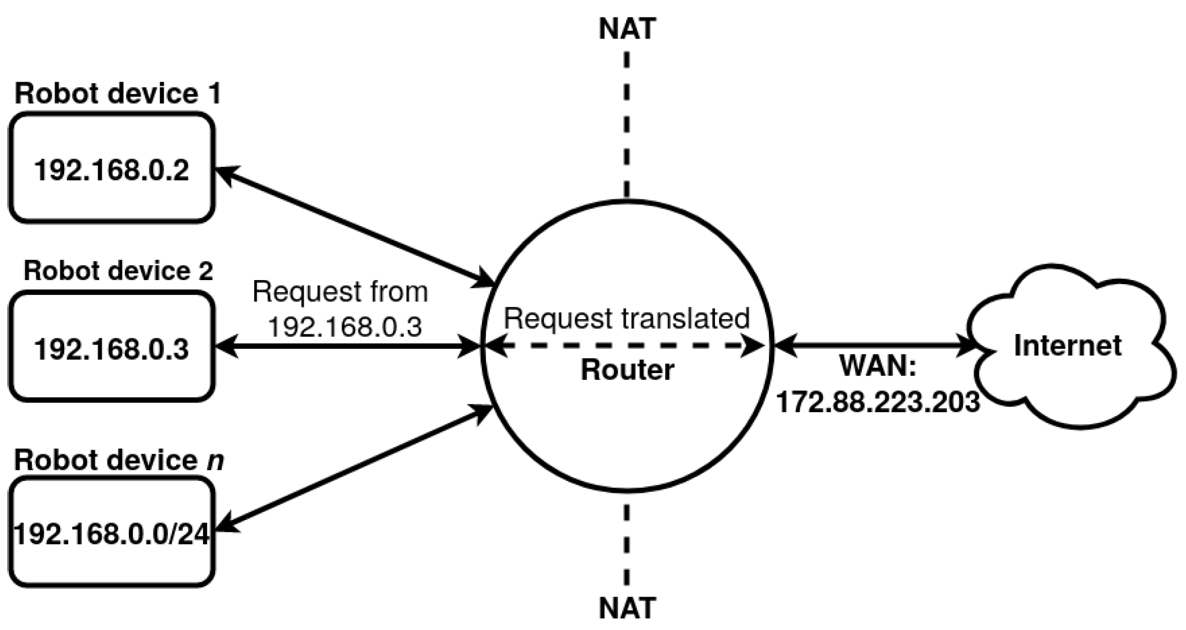
3.6. Tunnelling in Wireless Communications

Tunnelling is a network protocol that allows for the secure transmission of private data over a public (or private) network. It is a way of giving users of a public network access to network resources that they would not otherwise be able to reach [51]. In some rare instances, tunnelling is used to enable unsupported network protocols and to bypass firewalls. The nature of our private 5G network and public 4G network experiments required us to use tunnelling for this purpose. Our current 5G network setup uses a network address translation (NAT) layer, which hides any connected devices’ IP for better security. For research use cases and experimentation, the NAT layer presents an issue as it makes direct communication between connected devices impossible. The way of circumnavigating the issue is by creating a private tunnel connection between directly communicating devices, which is what has been carried out for the experiments described in Section 4. In the future, NAT forwarding will be enabled as a feature for the private 5G network to allow for direct communication without the need for tunnelling. However, for public 4G network experiments, removing the NAT layer is not an option, as it is controlled by the network carrier, and security is a very important and concerning issue on public networks. Thus, it will always be necessary to bypass the security measures put on public networks and to enable certain network protocols to run between the pseudo-MEC (server; MEC/GPU laptop) and the robot (client; on-board processor).
The public 4G network results presented in Section 4 and Section 5 are used to demonstrate the best possible communication performance achieved with current commercial technology available in rural areas; many farmers currently contend with sub-standard network performance, depending on the location of farm fields and what type of mobile network is available. Fourth-generation telecommunications is used as the “benchmark to beat” for 5G, while WiFi6, although restrictive in its use case in agriculture, is used to show how close 5G gets to a state-of-the-art wireless local area network (WLAN). A simplified network diagram in Figure 8 shows how NAT works for the 4G and 5G networks.
Unlike mobile networks, e.g., 3G, 4G, 5G, etc., WiFi, and by extension WiFi6, routers do not need to hide wireless local devices’ IP addresses. The functionality of NAT is usually required only when a device is connected to the internet (online), which is not always required by farmers. If a WiFi-enabled network is required to upload data to the cloud or to an online server, this can be carried out without introducing NAT to the local wireless area network. However, introducing an online component to WLANs can cause bottlenecks to occur due to low-throughput capabilities of a specific Internet service provider (ISP) or geographical area.
To achieve bidirectional communication for 4G and 5G, a peer-to-peer tunnelling network service was created using WireGuard [52]. Network tunnelling can increase delay if the network path taken between communicating devices is not direct, i.e., requests have to be made to the virtual private network (VPN) or tunnelling service; in addition, communication paths can take unknown hops to reach a destination. However, the tunnelling network for the private 5G network is made up of only two end-point laptops, which means that there is minimal delay in the system. For example, Donenfeld [52] performed tests using ideal conditions (two end-point devices connected with an Ethernet cable), and WireGuard achieved the lowest ping time against all other tested applications, with a latency of ~0.403 ms. A WireGuard experiment over the air cannot be conducted accurately enough as dynamic environment conditions are hard to measure precisely and are highly variable. However, from the latency results shown in Section 4.2, any delay introduced by WireGuard is considered insignificant.
To allow for two devices to directly communicate over a public network, a different type of WireGuard service is required, i.e., server–client tunnelling network. For example, the public 4G network experiments were configured using a WireGuard server–client tunnelling network to bypass the ISP gateway (anonymity) that comes with standard public wireless communications. However, this means that there is an increase in WireGuard delay path routing, and it is more complex to calculate true Round-Trip Time (RTT) latency.

4. Physical Experiments: Network Throughput and Latency

Wireless network experiments were conducted in four corners of two test environments: the Vegetable Polytunnel and the Walled Garden, mentioned in Section 3.3. In total, experiments were conducted in eight geographically dispersed points, and at each point, an experiment lasted 30 s and was repeated 5 times. The results are presented in Section 4.2. The commercial mapping tool What3Words (W3W) [53] was used to identify and mark the eight data collection points where experiments were conducted, illustrated in Figure 3a and Figure 4a. For ease of visualising the results in Section 4.2, the points used for data collection are labelled with the first letter of each W3W specification, as well as the location of the core network (access point) for the 5G-SA and WiFi6 networks. Note that for privacy reasons, the exact locations are not shared in this paper (i.e., abbreviated one-letter versions of the W3W tags are listed instead of the full tags). The approximate distances between each data collection point and the access points (5G-SA and WiFi6) are given in Figure 3b and Figure 4b. The physical experiments and results are discussed in Section 4.3.

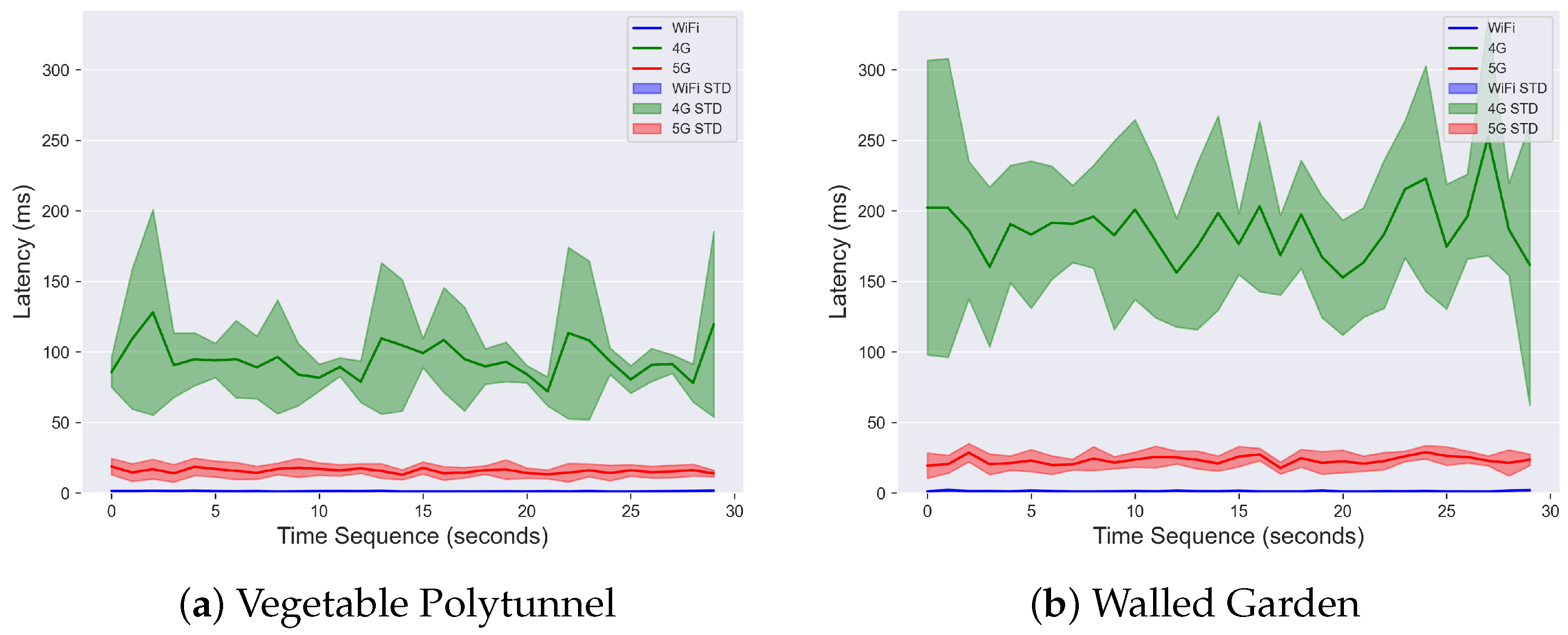
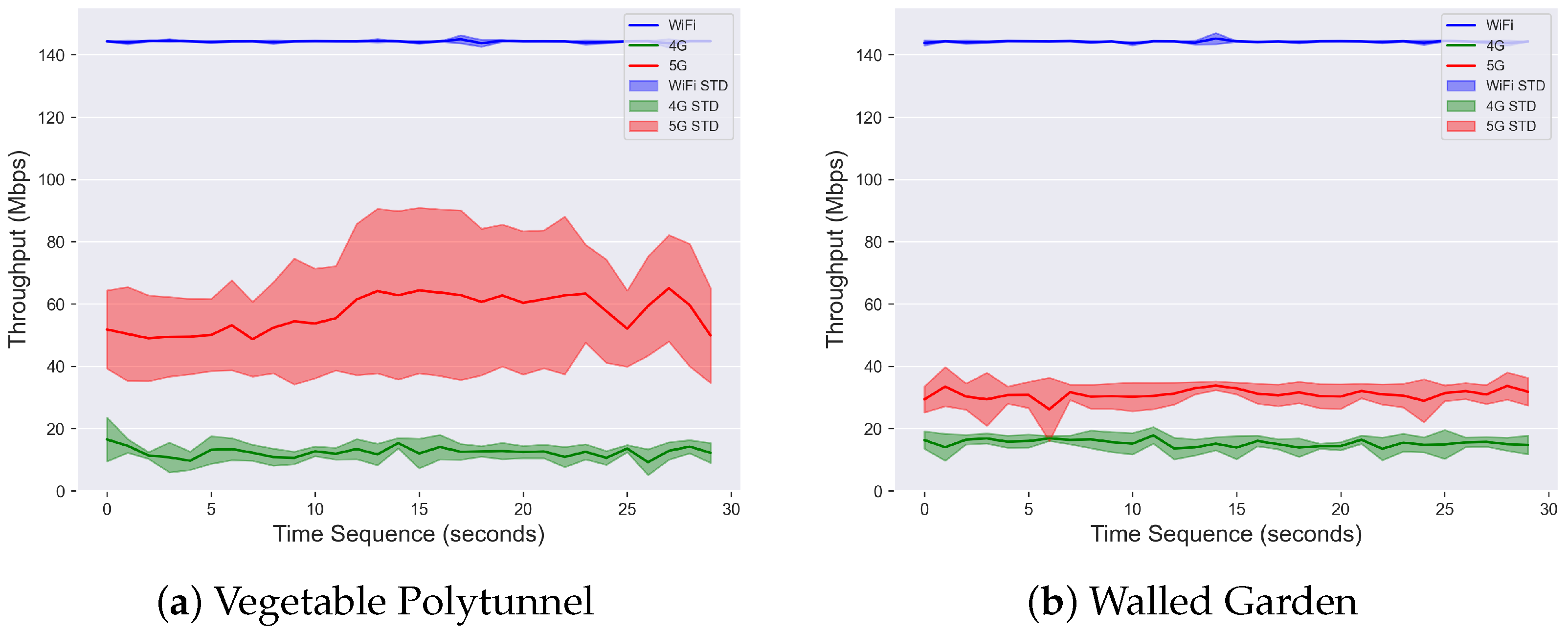
4.1. Performance Metrics

To test network stability and performance, three different video streaming settings were used, labelled as 1-RGB, 4-RGB and 1-RGBD, which describe in-field robot video data stream being transmitted to the MEC/GPU laptop using our 5G-SA network. Note that all video stream data in our experiments was compressed. The number prefix denotes the number of video streams, for example 1-RGB denotes one RGB video stream. The 1-RGB video stream experiment tests realistic latency conditions in what can be considered typical or medium network load. The 4-RGB video stream experiment is used to test how 4G, 5G-SA and WiFi6 deal with multiple (i.e., four) data streams communicating at the same time. Four video streams can be considered heavy network load, which is expected to increase latency for all network types. Finally, the 1-RGBD stream experiment is used as a method to analyse how the different networks react to a single source of consistent heavy network load. It is important to stress that it was never the intention of the authors to analyse maximum throughput or lowest latency, but rather to demonstrate the practical results and evaluate the comparative performance of state-of-the-art network systems (i.e., 5G-SA, WiFi6, and a commonly used commercial network system, i.e., 4G) within a real-world agricultural environment.
There were three independent variables in our experiments: location, network type and video stream number. There were two dependent variables, reflecting the raw data collected to assess performance: latency, measured in microseconds (ms); and throughput, measured in megabits per second (Mbps). The results are presented next.

4.2. Results

While a larger set of performance metrics were collected during the experiments described in this paper, a selected portion of the results that best illustrate our aims are reported here. For each of the two performance metrics, three statistics are presented: mean, standard deviation and minimum latency (ms); and mean, standard deviation and maximum throughput (Mbps).
Throughput results are interpreted from the point-of-view of the in-field mobile robot as the amount of data transmitted from the robot to the MEC/GPU laptop. Note that wherever “throughput” results are shown or discussed they depict the “data sent” performance metric. This data sent metric (from robot to MEC/GPU) is much higher in proportion to the data received (from MEC/GPU to robot), which is negligible. The data received by the robot are of a very small volume because the robot only receives basic network telemetry data, short control messages to start and stop a video stream, and co-ordinate information identifying weed locations in an image. As a consequence, here we focus only on the data sent from robot to MEC/GPU stream, and our analysis presented here considers only that stream.
The data collection point (geographical location) with the best results for latency (lowest mean and minimal latency) and throughput (highest mean and maximum throughput) is selected for each of the two environments and shown in Table 4 (for a complete view of all data collection points covering the six key performance metrics, refer to Appendix A). Figure 9 and Figure 10 show the data from Table 4 for each of the environments, Walled Garden and Vegetable Polytunnel. The wireless networks’ latency results ranking, in Figure 9, remained the same throughout all data collection points in both test environments. It was always the case that WiFi6 had the lowest latency followed by 5G-SA, whereas 4G had the highest latency, which was ten times higher than the latter. The ordering of the wireless networks’ performance remained similar for throughput, as shown in Figure 10.
In all instances, WiFi6 outperformed 5G-SA and greatly outperformed 4G. 5G-SA outperformed 4G in all environments. Finally, the distance between the two environments from each access point is averaged and compared for 5G-SA and WiFi6. The 5G-SA mast is an average distance of 66.0 m and 137.5 m from the Vegetable Polytunnel and Walled Garden, respectively; and the WiFi6 router is an average distance of 20.6 m and 23.5 m from the Vegetable Polytunnel and Walled Garden, respectively (a difference of 45.4 m and 114.0 m respectively, between the two corresponding environments and wireless networks).

4.3. Discussion

Our results demonstrate that commercially available public 4G is unrealistic to be used for high-data-rate and low-latency operations in the rural environment, rarely achieving below 100 ms latency and never managing to reach over 20 Mbps data throughput. We note that, on average, the public 4G network data rate we recorded is close to the quoted upload speeds of 14.7 Mbps [48]. It should be noted that the region surrounding the chosen test locations was thoroughly evaluated for the best 4G signal and network provider to achieve these results. Low throughput and high latency can result in poor performance of the in-field robot, resulting in potential misinterpretation and/or mislabelling of plants and/or erroneous robot localisation, even leading to robots causing damage to plants. A strength of public 4G networks for agriculture is that if a rural area has any network coverage, it is quick and easy to set up with little configuration required. However, this strength carries a weakness. Total control and availability of the network is in the control of the network carrier (ISP), within government regulations, of course. Moreover, a network-wide outage at the ISP means instant outage and potentially significant disruption to normal operations on a farm.
Public 5G, which is not evaluated in this work, is expected to perform with lower latency and higher data rate than public 4G. Hence, it can be assumed that public 5G can support high-data-rate, low-latency agri-robotics and the future smart farm. However, this is not the case currently, and it will remain so until public 5G fully matures, and even if it does, there is a chance that it will remain unrealistic to expect full coverage in rural areas, as is the case with public 4G. It needs to be considered that commercial networks do not apply a balanced TDD, i.e., more emphasis on download speed and delivering services, unlike a private network that can be configured to provide more balanced upload and download speeds and improve network coverage to more rural areas.
If we take a look at real-world data provided by Ookla [54] for Q1–Q2 of 2021, the highest 5G upload data achieved are 41.79 Mbps in South Korea. South Korea have been the leader in network technology and Internet infrastructure since the late 1990s/early 2000s [55], and they are world-leading in 5G as well [56]. Yet, the remaining bottleneck for public 5G seems to be upload speed. Getting over the maturity and configuration hurdle, the lack of control over the network and relying on an ISP, as is the case for 4G, remains an issue.
The private 5G-SA available at the University of Lincoln has proved why it is better than public 5G: by showing greater upload speeds achieved in real-world experiments of 57.1 Mbps with VLoS and 31.0 Mbps with NVLoS, Table 4. Public networks are typically tuned to maximise download speeds (e.g., for customers streaming video from cloud services), whereas the on-farm use case such as the one tested here will need to maximise upload speeds. The slowest average upload speed is approximately double that of the UK average according to [54]. Upload speeds over 30 Mbps can support at least one live video stream and bidirectional communication and 60 Mbps can support two live streams and bidirectional communication. Moreover, the latter case can support multiple live streams; however, video streaming will not be real-time and will not be running at 30 FPS. The private 5G 4-RGB streaming experiments showed significant reduction in video stream quality and speed, with some streams buffering for a few seconds before starting back up again. The fact that four video streams shared bandwidth meant that the system was trying to balance resources and all four streams were not running at the same speed, i.e., some smoother than others, whereas the 1-RGBD stream experiment experienced slowness or choppiness and was not running at 30 FPS. The expected bandwidth requirement for live RGBD video streaming is ~145.0 Mbps, 5G could support approximately half the required bandwidth.
The private WiFi6 (local) network was evaluated as it has recently become commercially available and it is state-of-the-art in terms of network features and performance, introducing higher network speeds and very low latency. It was expected that WiFi6 will beat 5G in data throughput, and in fact, it leads 5G by ~2.5 times in upload data speeds. WiFi6 unexpectedly beats 5G in latency time as well, by being as much as ~13 times lower. However, the distances at which these results are obtained are not the same as for 5G, and the NVLoS experienced by 5G is not present for WiFi6.
Our test location furthest from our WiFi6 router is 33.2 m, and from our 5G-SA access point is 154.8 m—more than 4.5 times further for signals to travel between robot and 5G-SA access point vs. WiFi6 router. The attenuation of a WiFi signal is exponential, and at a distance greater than 100 m, there would be no signal (communication) at all. A high-gain antenna could be used to boost WiFi signal; however, such antennae do not exist commercially for WiFi6. Moreover, a license needs to be obtained to operate such antennae for standard WiFi, making it very likely the case that WiFi6 will also require a license to operate signal-boosting antennae.
Even though our WiFi6 tests results are demonstrably better than 5G-SA, and at a completely different level compared to 4G, there are many situations where WiFi6 is not the best option for agriculture. For example, the experiments conducted in this work used only the WiFi6 standard, and support was disabled for older WiFi standards. This forced all devices to use the latest standard for message transmission, ensuring lowest possible latency and highest throughput. However, in practical environments (i.e., farm) it can be beneficial to enable multi-WiFi support, allowing certain sensors to use older standards, which may allow for greater compatibility, coverage and more robust signal strength to distance drop off (better attenuation at greater distances). Moreover, not many discrete and low-power WiFi6 network devices exist on the market. Most sensors used by agronomists or farmers for monitoring rainfall, soil moisture, light levels, etc., do not support WiFi6. Because of this, WiFi6 is less known, and not many real-world use cases and data exist yet.

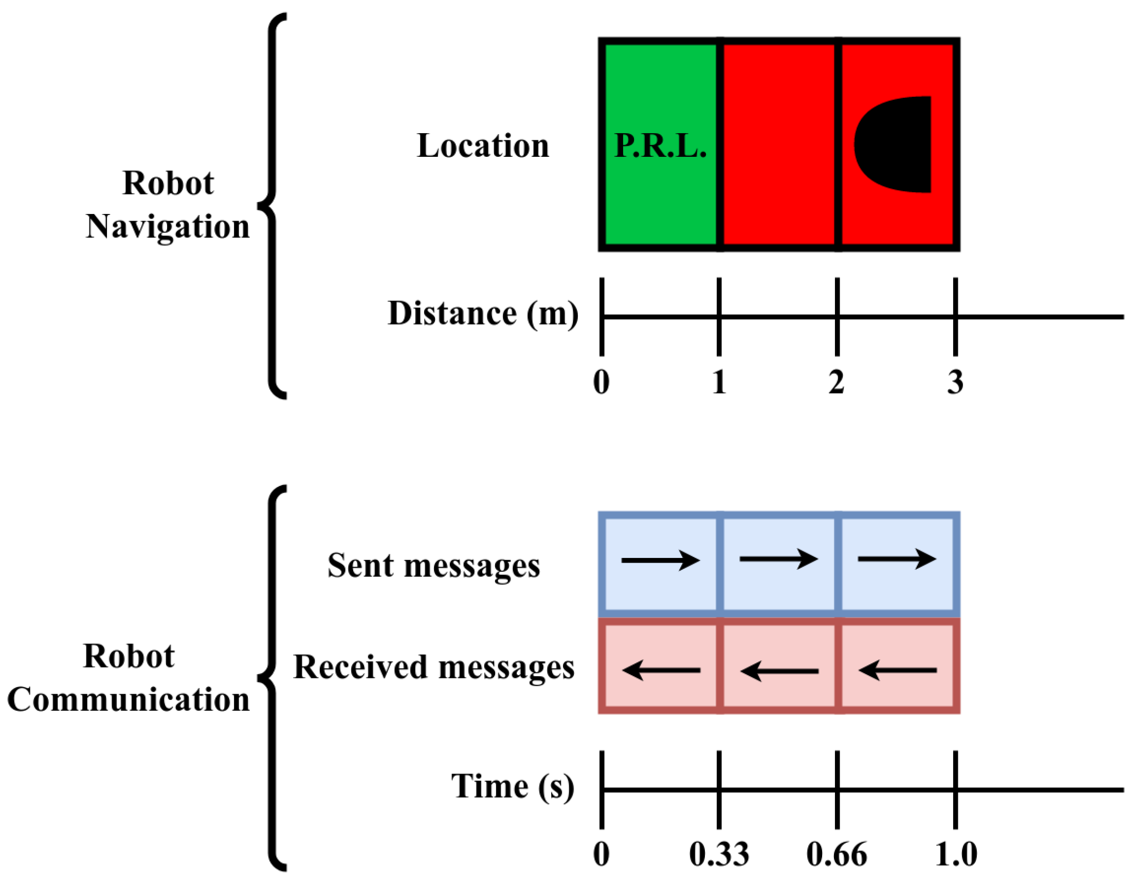
5. Simulated Experiment

Building on the results presented in the previous section, we devised a simulated experiment in order to analyse whether the latency values we obtained in our field tests are realistic for real-world in-field deployment. We aim to demonstrate that a wireless network can support real-time operation and control, where the robot in the field must receive relative locations of plants within its current frame of reference, before it transitions to a (substantially) new location. This is vital for the correct operation of a weed spraying robot, as it needs to be able to spray the weeds correctly, while maintaining its speed.
Here we describe the setup for the simulation experiments and our results.

5.1. Experiment Design

Our objective is to analyse the “real-time” delay in transmitting robot location information, comparing the different network types. To perform this simulated experiment, we used real-world Round-Trip Time (RTT) mean latency results from two arbitrarily chosen data collection points, P.R.L. and R.W.P. in the Vegetable Polytunnel. The 5G-SA and WiFi6 networks in the Vegetable Polytunnel have mostly VLoS with light obstructions, e.g., metal scaffolding, whereas the 4G network has some VLoS with moderate obstructions, e.g., tree lines, metal scaffolding and general RF interference that can occur over longer-distance communication.
We simulate a robot driving from one point to the other, as illustrated in Figure 11. We evaluated our simulated experiment twice: in each experiment, the RTT mean latency from one of the points—P.R.L. or R.W.P.—is used to estimate the accumulated delay experienced by the robot for each metre of travel as it drives from one point to the other. For every metre that the simulated robot moves, its location is updated and sent to the MEC (e.g., our MEC/GPU laptop) and a processed reply message is sent back. It is approximated that points P.R.L. and R.W.P. are 30 m apart; therefore, 30 location steps are generated, as shown in Figure 11. The simulated robot moves with a velocity of 3 m/s which means that every second, three location spaces are passed. For every metre the robot moves, one image message is sent from the robot to the MEC; the image is processed at the MEC and one weed location message (e.g., bounding box) is sent from the MEC to the robot, as described in Figure 12 and accompanying Table 5. The image-processing pipeline described in Section 3.2 can process images at speeds as fast as ≈14.5 ms per image. To further simplify the simulated experiments, robot velocity is assumed fixed and other external factors contributing to latency are ignored.
We make the assumption that the time that the robot is delayed while it waits for each message is simply the RTT latency time of the network at the given location plus the processing time. The message delay time is calculated as:
m s g _ d e l a y _ t i m e = s e n d _ t i m e + p r o c _ t i m e + r e c v _ t i m e
where s e n d _ t i m e = the time required to send a message from the robot to the MEC/GPU computer; p r o c _ t i m e = the time required to process the message on the MEC and prepare a command message in response; and r e c v _ t i m e = the time taken to send the command message from the MEC back to the robot.

5.2. Results

We have RTT latency for points P.R.L. and R.W.P. and no real-world data for the points in-between; as such, we cannot perform completely accurate evaluation of the message delay time for our simulated exercise. However, we assume the trend lines in Figure 13 are a good approximation of the RTT delay time; therefore, we can use the RTT latency of P.R.L. and R.W.P. as the two extremes for each network, the table in Figure 11, to analyse how the message delay time is affected.
Our simulated robot sends three location updates every metre it drives and requires a response within 0.333 s (333.3 ms) to allow it to carry out an operation while the location has not changed, i.e., in real time. Calculating the difference between the required response time and the message delay time provides allowable lag times for all three networks, as shown in Table 6. This result shows that if 4G was employed for communication, a robot would accumulate an overhead of between 3.4 s and 8.0 s (due to network lag) in just 10 s of travel, and therefore would not be able to operate within real time.
For further evaluation of the experiment results, we performed simple vertex-form quadratic calculations to visualise trend lines and observe the expected RTT latency over the 30 m path of the remote-controlled robot, as shown in Figure 13. This evaluation was only performed for 4G and 5G-SA as WiFi6 barely observed any demonstrable change over the 30 m path. Moreover, including WiFi6 to Figure 13a) greatly reduced the usefulness of the results and made them unclear as it skewed the y-axis in favour of WiFi6. The trend line for 5G reduces between point P.R.L. and R.W.P. even though the distance from the access point increases. This is because point R.W.P. has a more direct and open view of the central access point antenna, which is directly pointing at it and the signal does not have to go over the roof of a nearby building.

5.3. Discussion

Our simulated experiment produces a back-of-the envelope estimate of the ability for each type of network considered here to handle the real-time streaming traffic associated with a robot moving in a field and needing to perform live image analysis to guide in-field actuation, like spraying. The simulated experiment makes a number of assumptions about the network traffic, but does demonstrate the differences between the network types and shows that 4G is clearly insufficient. Another assumption made here is that the robot is moving very slowly, at 1 m/s. More realistically, a sprayer in a field usually drives at about 15 km/h or 4 m/s. This faster speed would necessarily increase the need to analyse images more quickly. Further experimentation and analysis is required to determine the number of images per second that need to be analysed. In some cases, a slower frame rate can suffice in order to support higher travel speeds of a robot in the field.

6. Conclusions

First, we summarise our results. Then, we close with a brief discussion of considerations for future work, including mention of our planned next steps.

6.1. Summary

This work draws two important conclusions. Firstly, it evaluates the performance of a private 5G-SA telecommunications network, a private WiFi6 network and a public 4G telecommunications network for the use case of high-throughput and low-latency operations. Experiments in Section 4 were conducted in the context of an agricultural use case: a robot capturing images in a field, streaming that video to an off-board edge computer for identifying weeds and sending actuation commands back to the robot. The results demonstrated that public 4G cannot be used in agriculture to support high-throughput and low-latency operation. Further, in our controlled setting, we found that WiFi6 performed better than 5G-SA. WiFi6 never saturated during throughput testing, whilst 5G-SA saturated at approximately 60 Mbps when testing 1-RGBD video streaming. According to [54], the achieved throughput is higher than leading countries’ public 5G results from gathered data in Q1–Q2 of 2021. However, these results show a good outcome overall for 5G, as it shows that the technology is still maturing. WiFi6 had a lower latency on average of 18.2 ms compared to that of 5G-SA. The 5G-SA mast is further by 45.4 m and 114.0 m in the Vegetable Polytunnel and Walled Garden, respectively, compared to the WiFi6 router. The greater distance from the access point further contributes to the worse performance in the Walled Garden for the 5G-SA network. However, this highlights the 5G-SA network’s coverage over a greater distance and—a feature not tested—support for connecting a greater amount of devices. WiFi/WiFi6 routers can support a few devices; any increase in number of devices can greatly increase complexity, whereas the 5G-SA network can inherently support a greater number of devices with gradual increase in complexity. It is worth noting that the obtained results are only a snapshot of the private 5G-SA performance at the time of data collection. Our 5G-SA system is continuously being updated and improved, making it more robust and balancing the upload and download ratio for different use cases.
Secondly, a simulated experiment was conducted in order to assess the viability of performing a more complex hypothetical variant of our agricultural use case using each of the three network setups. Specifically, this experiment analysed latency. As previously observed, these results reaffirmed that 4G is too slow to be able to perform the task at hand. The WiFi6 and 5G-SA produced sufficient speed to manage the job. Furthermore, the results showed that only in extreme cases, where the processing time is longer or the velocity of the robot is greater, will WiFi6 have advantage over 5G-SA.
In conclusion, the results in this body of work are significant for the agricultural domain. They clearly identify strengths and weaknesses of current and state-of-the-art wireless network infrastructures for use in rural environments. Moreover, our results identify fundamental requirements that future smart farms will ask of the telecommunications industry. It is clear that 4G cannot support agricultural activities; and the smaller coverage area, higher attenuation and much slower commercial uptake of WiFi6 make it an impractical solution. The “illumination” of the target area by private 5G masts can be designed to avoid high attenuation and fresnel edges, like trees and buildings, whereas public 4G cannot, and as a result, the consistency of results on public 4G will be compromised. Finally, this work highlights that there is no single wireless network that is best suited for agri-technology and agri-robotics, but using a mixture of the state of the art can provide a better solution. For example, private 5G can be used to move data faster between longer distances connected to a WiFi6 (or multi-WiFi) wireless backhaul that extends to locally connected robots and sensors in a farm field.

6.2. Considerations for Future Work

Deploying agricultural robots will involve not only solving technical problems such as those outlined here, but also a range of social issues that are not addressed within the scope of this article. These include factors such as farmer acceptance of robotic technologies, where attitudes towards and experience with technology can vary greatly. Our experience in other work where we are developing robots to operate alongside workers in fields is that any solutions that can increase yield are attractive to farm managers and any solutions that increase earnings are attractive to farm workers, who are often paid on a “piece rate” (e.g., how much volume they harvest).
While this article has focussed on the advantages of 5G, there are also a number of disadvantages. For example, propagation distances are reduced due to increased frequency/power restrictions; therefore, the number of cells required to cover large agricultural areas increases. In addition, regulatory issues such as government licenses for operating a private network can be prohibitive, from logistical and/or cost perspectives. The installation and maintenance of a private network can require specialist personnel. For example, the matching of transmitter/receiver capabilities of a 5G system to the task(s) for which the system is deployed is crucial to ensure compatibility and to achieve maximum throughput and desired functionality. Reliability and power consumption are other operational issues that may be problematic for farmers. Utility costs may increase if more technology is integrated on the farm (especially electronic vehicles, which is the case for many new robots being developed). In addition, the more a farm increases its dependency on networking, the more impactful network outages will be. In the extreme case, crops are not harvested on time because networked equipment (like robots) cannot operate, leading to potentially significant food waste and nullifying all the good intentions of agri-robots.
One alternative networking technology not considered in this article is LoRaWAN [57]. LoRaWAN can be used in some supplementary in-field sensors, for example, low-power soil detection and phenotyping sensors throughout a farm field. However, LoRaWAN cannot deal with sustained high-throughput communication for resource-intensive tasks. However, that is not to say that LoRaWAN should not be used, nor that high-throughput network infrastructure cannot and will not use other wireless technologies. On the contrary, we envision future farms supporting multiple networks. For example, once a 5G network with multiple nodes is established in an area, a WiFi(6) mesh network could be used as a backhaul where required and such edge compute nodes could have support for multiple technologies, such as LoRaWAN. Therefore, in the example demonstrated here, the edge node could gather the data from the different wireless nodes (e.g., in-field robots) and communicate it across the network (even to the cloud) via 5G.
In a practical farm environment with large farm fields and great distances across and between them, more than a single 5G node or WiFi(6) router will be required. Our use cases are presented as proof-of-concept and showcasing what each of these high-performing wireless technologies can do when they are individually isolated. However, in a more practical environment, 5G will be deployed with more nodes (antennas) and with a mixture of 5G features, such as mmWave and sub-6GHz frequencies. If only a WiFi6 solution is employed, it would require many nodes and high-powered antennas to try and reach further distances. However, there is a hybrid use case where a WiFi6 mesh supplements 5G networking, by receiving a 5G signal and allowing for multiple robots to connect via WiFi6 to a main WiFi6 node which would connect these devices to the main 5G network and allow for offloading to edge compute devices or other cloud infrastructure.
The next steps with our research involve testing more complex scenarios in a physical environment. This includes the hypothetical setup simulated in Section 5, as well as setups with multiple robots in the field, in larger fields (where the distance to the network mast is greater) and handling more complex actuation messages going to the robot such that “send” and “receive” transmissions are more balanced than in the experiments presented here. As public 5G roll-out continues world-wide, having better understanding of the benefits in agriculture will help farmers make the case for rural deployments of such networks. The contribution of the work shared here helps to demonstrate that the wireless infrastructure of 5G is required to facilitate even the most basic precision agriculture use case.

Author Contributions

The first two authors (T.Z. and E.I.S.) collaborated on system deployment, experiment design and analysis, and writing; the last two authors (D.B. and S.P.) contributed to the wider vision and potential impact of 5G in the agri-food domain. All authors have read and agreed to the published version of the manuscript.

Funding

This research was funded by Ceres Agri-tech grant number IC10P1 and Research England under the Lincoln Agri-Robotics grant (Expanding Excellence in England programme).

Data Availability Statement

The data are not publicly available due to privacy.

Conflicts of Interest

The authors declare no conflict of interest.

Appendix A

Table A1. Experimental results from Vegetable Polytunnel locations representing the best run over five 30 s runs in each location. Entries in bold highlight the best experiment, as summarised in Table 4. ** Results corrupted.
LatencyThroughput
Location Network Stream Mean Std Min Max Mean Std Min Max
P . R . L . 4G1-RGB216.726.1152.7259.79.10.58.310.2
P . R . L . 5G-SA1-RGB63.986.414.4374.317.42.112.821.1
P . R . L . WiFi61-RGB1.20.21.01.818.60.617.719.8
P . R . L . 4G4-RGB1115.0681.00.02616.910.61.96.814.6
P . R . L . 5G-SA4-RGB44.262.322.6359.551.93.642.361.0
P . R . L . WiFi64-RGB1.40.31.02.374.70.572.575.2
P . R . L . 4G1-RGBD1354.3395.3658.12179.68.01.65.511.4
P . R . L . 5G-SA1-RGBD22.62.917.227.457.15.848.765.1
P . R . L . WiFi61-RGBD2.83.91.123.1144.20.2143.6144.6
M . V . F . 4G1-RGB293.833.4235.8364.510.50.98.512.5
M . V . F . 5G-SA1-RGB32.323.415.3137.331.64.024.739.5
M . V . F . WiFi61-RGB1.20.21.01.616.80.516.117.4
M . V . F . 4G4-RGB680.5242.6333.31164.011.81.09.313.9
M . V . F . 5G-SA4-RGB26.212.114.383.641.40.440.442.3
M . V . F . WiFi64-RGB1.40.31.01.961.61.660.266.4
M . V . F . 4G1-RGBD1430.3408.8687.02356.19.21.66.412.3
M . V . F . 5G-SA1-RGBD****************
M . V . F . WiFi61-RGBD2.10.81.14.2144.20.2143.7145.0
R . W . P . 4G1-RGB294.0137.9130.3574.59.70.98.311.2
R . W . P . 5G-SA1-RGB22.919.810.9124.622.90.820.123.8
R . W . P . WiFi61-RGB1.30.21.01.813.70.512.814.7
R . W . P . 4G4-RGB928.4484.7231.91983.57.91.55.210.5
R . W . P . 5G-SA4-RGB31.716.920.1110.838.21.434.741.8
R . W . P . WiFi64-RGB1.70.71.03.7100.67.291.3113.2
R . W . P . 4G1-RGBD301.691.7182.4637.98.80.87.310.6
R . W . P . 5G-SA1-RGBD22.33.715.833.047.54.438.855.0
R . W . P . WiFi61-RGBD4.15.61.124.5144.20.3142.8144.5
D . L . F . 4G1-RGB94.913.072.0128.010.40.010.310.4
D . L . F . 5G-SA1-RGB15.71.612.918.723.30.222.723.6
D . L . F . WiFi61-RGB2.14.31.024.318.30.617.119.0
D . L . F . 4G4-RGB1850.8391.7990.72398.812.51.69.216.5
D . L . F . 5G-SA4-RGB18.92.213.923.343.52.241.449.9
D . L . F . WiFi64-RGB1.50.61.02.966.40.865.568.4
D . L . F . 4G1-RGBD1252.2218.3896.71904.610.21.46.613.7
D . L . F . 5G-SA1-RGBD18.91.914.122.445.83.538.952.2
D . L . F . WiFi61-RGBD2.71.11.17.2144.10.2143.5144.4
Table A2. Experimental results from Walled Garden locations representing the best run over five 30 s runs in each location. Entries in bold highlight the best experiment, as summarised in Table 4.
LatencyThroughput
Location Network Stream Mean Std Min Max Mean Std Min Max
A . C . D . 4G1-RGB787.1672.40.02327.82.80.61.74.2
A . C . D . 5G-SA1-RGB550.825.6479.1579.510.30.210.110.8
A . C . D . WiFi61-RGB1.30.21.01.716.91.116.220.3
A . C . D . 4G4-RGB831.5148.0362.01132.22.40.31.83.1
A . C . D . 5G-SA4-RGB1098.4559.10.02155.98.71.26.612.4
A . C . D . WiFi64-RGB2.23.91.022.966.73.759.377.5
A . C . D . 4G1-RGBD217.622.3182.8262.311.60.610.412.8
A . C . D . 5G-SA1-RGBD2229.461.51929.42297.010.50.010.510.5
A . C . D . WiFi61-RGBD2.91.51.17.8144.20.3143.3144.6
A . C . J . 4G1-RGB198.435.0137.6299.313.91.711.016.4
A . C . J . 5G-SA1-RGB1279.0155.9953.41442.511.70.211.212.2
A . C . J . WiFi61-RGB5.09.01.135.724.43.315.928.0
A . C . J . 4G4-RGB774.2139.9563.41102.615.41.113.517.8
A . C . J . 5G-SA4-RGB2390.4193.81848.72697.014.71.012.816.9
A . C . J . WiFi64-RGB12.210.82.641.389.01.187.191.8
A . C . J . 4G1-RGBD604.6140.9372.21005.912.50.710.613.4
A . C . J . 5G-SA1-RGBD1464.970.81349.51628.819.31.716.821.0
A . C . J . WiFi61-RGBD15.812.82.748.0143.82.6137.4149.5
O . L . D . 4G1-RGB963.7489.7235.82184.72.90.81.34.2
O . L . D . 5G-SA1-RGB23.12.817.728.912.70.112.513.2
O . L . D . WiFi61-RGB1.30.21.02.022.30.121.922.5
O . L . D . 4G4-RGB575.5368.40.01157.82.71.00.64.9
O . L . D . 5G-SA4-RGB795.9188.4424.21391.531.01.526.233.8
O . L . D . WiFi64-RGB1.70.81.05.183.10.481.783.8
O . L . D . 4G1-RGBD249.626.9200.3324.18.10.57.29.4
O . L . D . 5G-SA1-RGBD817.751.6726.7952.126.82.122.530.7
O . L . D . WiFi61-RGBD4.25.51.325.2144.20.4142.7145.1
L . V . C . 4G1-RGB187.221.2152.7252.310.50.98.712.1
L . V . C . 5G-SA1-RGB393.8210.094.9683.218.40.917.120.1
L . V . C . WiFi61-RGB1.40.41.02.222.10.121.922.5
L . V . C . 4G4-RGB500.3258.2200.41117.89.11.06.911.0
L . V . C . 5G-SA4-RGB1977.1145.31715.52358.617.61.514.019.7
L . V . C . WiFi64-RGB3.34.11.124.085.10.484.586.0
L . V . C . 4G1-RGBD257.531.0199.9334.88.70.67.29.8
L . V . C . 5G-SA1-RGBD1339.268.31237.71553.910.50.010.510.5
L . V . C . WiFi61-RGBD5.35.71.225.3144.20.3143.7145.2
To give a complete visual picture of our findings and data collection from experiments in Section 4, we have collated and plotted all the data in simple and easy-to-read graphs. The data are split into two main figures; each figure represents one of the two main performance metrics being analysed, i.e., latency in Figure A1 and network throughput in Figure A2. Each figure contains three subplots and each subplot represents a wireless network, i.e., 4G, 5G, WiFi6. Finally, each subplot is split by a vertical line into three sections, highlighting the data stream network parameter, and bar colour represents one of the two locations where experiments were conducted.
The public 4G latency performance in Figure A1 is poor throughout all streaming experiments and in all environments. Unlike WiFi6 and the private 5G, for 4G, it is difficult to analyse if the environment or the different streaming experiments cause an increase in latency; this is because the RF interference over a larger distance is impossible to predict. However, it can be confirmed that the latency is far too high for real-time video streaming, regardless of what type of streaming experiment is conducted.
The latency for 5G in Figure A1 is extremely low, and it is close to WiFi6 in the Vegetable Polytunnel environment (orange-coloured bars). However, in a distant environment, obstructed by tree cover and a wall, it suffers greatly, and in certain parts of the environment, the latency is as bad or worse than the public 4G (ACJ-4).
The latency results in Figure A1 for WiFi6 standard deviation indicates negative latency, which is impossible. This is because the latency is so low, and on occasion it can spike, making the negative portion of the standard deviation dip below zero. This makes WiFi6’s standard deviation negligible, it is kept for illustrative purposes. The main increase in latency for WiFi6 can be seen during the RGB-D data streaming experiments and when operating in an open field in the Walled Garden. This is expected for WiFi6, as signal loss in an open field is far greater than in an indoor space or a space with many walls and obstacles. The latency still remains extremely low.
The public 4G throughput results in Figure A2 are interesting, as regardless of the streaming experiment, they hit a certain limit of throughput. As suggested, from our own experiments on public 4G and from the data obtained from [48], the maximum and mean throughput (upload speed) should be between 20 Mbps and 14.7 Mbps, which is what we see. Albeit, there are some experiment locations that have much lower throughput, which could be caused by many factors, e.g., RF interference, increased traffic load, traffic load optimisation, etc. Therefore, we can assume that we are saturating the upload speed of the public 4G network and we cannot expect much higher throughput.
The 5G throughput results are impressive, and clearly much higher than 4G. However, if we examine the throughput results between WiFi6 and 5G, specifically for the RGB-D streaming experiment, we can see that the 5G network has also saturated in terms of upload speed. We can assume that the 5G network maximum upload speed is close to 65 Mbps. It was never the intention of this body of work to find the maximum upload speed of the particular configuration of the 5G network setup at the University of Lincoln, because the 5G network is continuously being improved, and, for example, UL/DL ration in the future can be configurable.
For the current release of 5G-SA N77, it is not (at least not to our knowledge). Moreover, there are different 5G network technologies and different iterations of 5G that will perform completely differently to each other, we would not be contributing to the field by specifically finding the limits of our particular system, which itself is continually evolving.
The WiFi6 throughput results are almost perfectly aligned with theoretical expectations. The RGB data stream is compressed, and throughput increases only if movement is detected and there are many different colour changes in very fast succession in front of the camera, which does not occur in our green and brown images; the throughput is variable and unpredictable. However, for the RGB-D experiments, the data stream is still compressed, but at a static rate. This means that the data streamed should always be the exact same regardless of how fast the scene in front of the camera changes and regardless of colour changes. Theoretically, this value should be 144 Mbps (or 18 MBps), which is what WiFi6 approximately reaches during the RGB-D experiments. Clearly, WiFi6 can stream the data it is expected to, and we have not reached a saturation limit of upload or download. However, the latency results, which are excellent, show the one weakness of WiFi6. In an outdoor open field environment, the signal loss will be exponential.
Figure A1. Latency results across all performance metrics and parameters. The vertical lines separate the data stream type, and the orange-coloured bars represent the Vegetable Polytunnel and the blue-coloured bars represent the Walled Garden.
Machines 11 01064 g0a1
Figure A2. Throughput results across all performance metrics and parameters. The vertical lines separate the data stream type, and the orange-coloured bars represent the Vegetable Polytunnel and the blue-coloured bars represent the Walled Garden.
Machines 11 01064 g0a2

References

  1. Webb, P.; Benton, T.G.; Beddington, J.; Flynn, D.; Kelly, N.M.; Thomas, S.M. The urgency of food system transformation is now irrefutable. Nat. Food 2020, 1, 584–585. [Google Scholar] [CrossRef] [PubMed]
  2. Borsellino, V.; Schimmenti, E.; El Bilali, H. Agri-Food Markets towards Sustainable Patterns. Sustainability 2020, 12, 2193. [Google Scholar] [CrossRef]
  3. GOV.UK. Press Release: £25 Million Funding for High Tech Machinery on Farms. Available online: https://www.gov.uk/government/news/25-million-funding-for-high-tech-machinery-on-farms (accessed on 19 January 2022).
  4. DEFRA. Third Report of Session 2021–22: Tree Planting. Technical Report HC356, House of Commons, Environment, Food and Rural Affairs Committee. Available online: https://committees.parliament.uk/publications/9364/documents/160849/default/ (accessed on 8 March 2022).
  5. Duckett, T.; Pearson, S.; Blackmore, S.; Grieve, B.; Chen, W.H.; Cielniak, G.; Cleaversmith, J.; Dai, J.; Davis, S.; Fox, C.; et al. Agricultural Robotics: The Future of Robotic Agriculture. arXiv 2018, arXiv:1806.06762. [Google Scholar]
  6. Zhivkov, T.; Gomez, A.; Gao, J.; Sklar, E.; Parsons, S. The need for speed: How 5G communication can support AI in the field. In Proceedings of the UKRAS21 Conference: Robotics at Home, UK-RAS, Virtual, 2 June 2021. [Google Scholar] [CrossRef]
  7. Tang, Y.; Dananjayan, S.; Hou, C.; Guo, Q.; Luo, S.; He, Y. A survey on the 5G network and its impact on agriculture: Challenges and opportunities. Comput. Electron. Agric. 2021, 180, 105895. [Google Scholar] [CrossRef]
  8. Lang, T.; McKee, M. The reinvasion of Ukraine threatens global food supplies. BMJ 2022, 376, o676. [Google Scholar] [CrossRef] [PubMed]
  9. Rae, M. The Economic Impact of the Ukraine–Russia War. In SAGE Business Cases; SAGE Publications: Thousand Oaks, CA, USA, 2022. [Google Scholar]
  10. Partridge, J.; Partington, R. ‘The anxiety is off the scale’: UK farm sector worried by labour shortages. The Guardian, 25 August 2021. [Google Scholar]
  11. Washburn, K. In California farm country, growers struggle with labor shortage. USA Today, 4 April 2020. [Google Scholar]
  12. Naik, G. Global farming suffers from falling prices, labor shortages as virus spreads. S & P Global Market Intelligence, 2 April 2020. [Google Scholar]
  13. Raza, A.; Razzaq, A.; Mehmood, S.S.; Zou, X.; Zhang, X.; Lv, Y.; Xu, J. Impact of Climate Change on Crops Adaptation and Strategies to Tackle Its Outcome: A Review. Plants 2019, 8, 34. [Google Scholar] [CrossRef] [PubMed]
  14. Borrelli, P.; Robinson, D.A.; Panagos, P.; Lugato, E.; Yang, J.E.; Alewell, C.; Wuepper, D.; Montanarella, L.; Ballabio, C. Land use and climate change impacts on global soil erosion by water (2015–2070). Proc. Natl. Acad. Sci. USA 2020, 117, 21994–22001. [Google Scholar] [CrossRef]
  15. Shaheb, M.R.; Venkatesh, R.; Shearer, S.A. A Review on the Effect of Soil Compaction and its Management for Sustainable Crop Production. J. Biosyst. Eng. 2021, 46, 417–439. [Google Scholar] [CrossRef]
  16. Millard, A.G.; Ravikanna, R.; Groß, R.; Chesmore, D. Towards a Swarm Robotic System for Autonomous Cereal Harvesting. In Proceedings of the Towards Autonomous Robotic Systems, London, UK, 3–5 July 2019; Althoefer, K., Konstantinova, J., Zhang, K., Eds.; Springer International Publishing: Cham, Switzerland, 2019; pp. 458–461. [Google Scholar]
  17. Global Livestock Environmental Assessment Model (GLEAM), Food and Agriculture Organisation of the United Nations. 2022. Available online: https://www.fao.org/gleam/results/en (accessed on 23 July 2022).
  18. Stafford, J.V. Implementing Precision Agriculture in the 21st Century. J. Agric. Eng. Res. 2000, 76, 267–275. [Google Scholar] [CrossRef]
  19. Gebbers, R.; Adamchuk, V.I. Precision Agriculture and Food Security. Science 2010, 327, 828–831. [Google Scholar] [CrossRef]
  20. Durisi, G.; Koch, T.; Popovski, P. Toward Massive, Ultrareliable, and Low-Latency Wireless Communication with Short Packets. Proc. IEEE 2016, 104, 1711–1726. [Google Scholar] [CrossRef]
  21. Popovski, P.; Trillingsgaard, K.F.; Simeone, O.; Durisi, G. 5G wireless network slicing for eMBB, URLLC, and mMTC: A communication-theoretic view. IEEE Access 2018, 6, 55765–55779. [Google Scholar] [CrossRef]
  22. 5G Network Coverage Outlook. Available online: https://www.ericsson.com/en/reports-and-papers/mobility-report/dataforecasts/network-coverage (accessed on 1 July 2022).
  23. Rendon Schneir, J.; Xiong, Y. A cost study of fixed broadband access networks for rural areas. Telecommun. Policy 2016, 40, 755–773. [Google Scholar] [CrossRef]
  24. Adami, D.; Giordano, S.; Tamburello, M. A Monitoring Application for Animal Repelling Devices in Smart Agriculture. In Proceedings of the 2020 IEEE 25th International Workshop on Computer Aided Modeling and Design of Communication Links and Networks (CAMAD), Pisa, Italy, 14–16 September 2020; pp. 1–6. [Google Scholar] [CrossRef]
  25. Kagan, C.R.; Arnold, D.P.; Cappelleri, D.J.; Keske, C.M.; Turner, K.T. Special report: The Internet of Things for Precision Agriculture (IoT4Ag). Comput. Electron. Agric. 2022, 196, 106742. [Google Scholar] [CrossRef]
  26. Tao, W.; Zhao, L.; Wang, G.; Liang, R. Review of the internet of things communication technologies in smart agriculture and challenges. Comput. Electron. Agric. 2021, 189, 106352. [Google Scholar] [CrossRef]
  27. Karthikkumar, M.; Premchandran, V.; Sathish, E. An Agricultural Irrigatıon Management System Based on the Internet of Things With MQTT Protocol. IOP Conf. Ser. Mater. Sci. Eng. 2021, 1084, 012118. [Google Scholar] [CrossRef]
  28. Bodunde, O.; Adie, U.; Ikumapayi, O.; Akinyoola, J.; Aderoba, A. Architectural design and performance evaluation of a ZigBee technology based adaptive sprinkler irrigation robot. Comput. Electron. Agric. 2019, 160, 168–178. [Google Scholar] [CrossRef]
  29. Tsipis, A.; Papamichail, A.; Koufoudakis, G.; Tsoumanis, G.; Polykalas, S.E.; Oikonomou, K. Latency-Adjustable Cloud/Fog Computing Architecture for Time-Sensitive Environmental Monitoring in Olive Groves. AgriEngineering 2020, 2, 175–205. [Google Scholar] [CrossRef]
  30. Maraveas, C.; Bartzanas, T. Application of Internet of Things (IoT) for Optimized Greenhouse Environments. AgriEngineering 2021, 3, 954–970. [Google Scholar] [CrossRef]
  31. Batte, M.T.; Ehsani, M.R. The economics of precision guidance with auto-boom control for farmer-owned agricultural sprayers. Comput. Electron. Agric. 2006, 53, 28–44. [Google Scholar] [CrossRef]
  32. Panfilov, I.; Mann, D.D. The importance of real-time visual information for the remote supervision of an autonomous agricultural machine. Can. Biosyst. Eng. 2018, 60, 2.11–2.18. [Google Scholar] [CrossRef]
  33. Gomez, A.S.; Aptoula, E.; Parsons, S.; Bosilj, P. Deep Regression Versus Detection for Counting in Robotic Phenotyping. IEEE Robot. Autom. Lett. 2021, 6, 2902–2907. [Google Scholar] [CrossRef]
  34. Choi, T.; Would, O.; Gomez, A.S.; Cielniak, G. Self-supervised Representation Learning for Reliable Robotic Monitoring of Fruit Anomalies. arXiv 2021, arXiv:2109.10135. [Google Scholar]
  35. Ponnambalam, V.R.; Fentanes, J.P.; Das, G.; Cielniak, G.; Gjevestad, J.G.O.; From, P.J. Agri-Cost-Maps-Integration of Environmental Constraints into Navigation Systems for Agricultural Robots. In Proceedings of the 2020 6th International Conference on Control, Automation and Robotics (ICCAR), Singapore, 20–23 April 2020; pp. 214–220. [Google Scholar] [CrossRef]
  36. Cox, J.; Tsagkopoulos, N.; Rozsypálek, Z.; Krajník, T.; Sklar, E.I.; Hanheide, M. Visual teach and generalise (VTAG)–Exploiting perceptual aliasing for scalable autonomous robotic navigation in horticultural environments. Comput. Electron. Agric. 2023, 212, 108054. [Google Scholar] [CrossRef]
  37. Salazar-Gomez, A.; Darbyshire, M.; Gao, J.; Sklar, E.I.; Parsons, S. Beyond mAP: Towards practical object detection for weed spraying in precision agriculture. In Proceedings of the IEEE/RSJ International Conference on Intelligent Robots and Systems (IROS), Kyoto, Japan, 23–27 October 2022. [Google Scholar]
  38. Available online: https://www.leorover.tech/ (accessed on 1 June 2023).
  39. Available online: https://www.intelrealsense.com/depth-camera-d435/ (accessed on 1 June 2023).
  40. Jocher, G.; Stoken, A.; Borovec, J.; NanoCode012; Chaurasia, A.; TaoXie; Changyu, L.; V, L.; Laughing; tkianai; et al. ultralytics/yolov5: v5.0—YOLOv5-P6 1280 models, AWS, Supervise.ly and YouTube integrations. Zenodo 2021. [Google Scholar] [CrossRef]
  41. Available online: https://www.asus.com/uk/Laptops/For-Gaming/TUF-Gaming/ (accessed on 1 June 2023).
  42. Available online: https://www.bt.com/ (accessed on 1 June 2023).
  43. Available online: https://www.nokia.com/ (accessed on 1 June 2023).
  44. Ofcom. Available online: https://www.ofcom.org.uk/home (accessed on 1 June 2023).
  45. Available online: https://static.tp-link.com/2021/202103/20210311/ArcherAX6000(EU&US)2.0_Datasheet.pdf (accessed on 1 June 2023).
  46. Available online: https://www.dlink.com/en/products/dwm-222-4g-lte-usb-adapter (accessed on 1 June 2023).
  47. Available online: https://ee.co.uk/ (accessed on 1 June 2023).
  48. Ofcom. Ofcom Publishes 4G and 3G Mobile Broadband Speeds Research. 2014. Available online: https://www.ofcom.org.uk/about-ofcom/latest/media/media-releases/2014/3g-4g-bb-speeds (accessed on 12 January 2022).
  49. D-Link. DWM-222 4G LTE USB Adapter. 2020. Available online: https://eu.dlink.com/uk/en/-/media/consumer_products/dwm/dwm-222/datasheet/dwm_222_a2_datasheet_en_eu.pdf (accessed on 17 November 2022).
  50. Available online: https://www.speedtest.net/ (accessed on 1 June 2023).
  51. Cisco. Tunneling. Available online: https://www.cisco.com/c/en/us/products/ios-nx-os-software/tunneling/index.html (accessed on 1 June 2023).
  52. Donenfeld, J.A. WireGuard: Next Generation Kernel Network Tunnel. 2020. Available online: https://www.wireguard.com/papers/wireguard.pdf (accessed on 1 June 2023).
  53. Available online: https://what3words.com (accessed on 1 June 2023).
  54. Fomon, J. The U.K. Is Ahead of European Trade Partners for 5G, Can’t Beat South Korea and China. 2021. Available online: https://www.ookla.com/articles/5g-united-kingdom-q1-q2-2021 (accessed on 1 June 2023).
  55. Lee, H.; O’Keefe, R.M.; Yun, K. The Growth of Broadband and Electronic Commerce in South Korea: Contributing Factors. Inf. Soc. 2003, 19, 81–93. [Google Scholar] [CrossRef]
  56. Massaro, M.; Kim, S. Why is South Korea at the forefront of 5G? Insights from technology systems theory. Telecommun. Policy 2022, 46, 102290. [Google Scholar] [CrossRef]
  57. Lavric, A.; Petrariu, A.I. LoRaWAN communication protocol: The new era of IoT. In Proceedings of the International Conference on Development and Application Systems (DAS), Suceava, Romania, 24–26 May 2018; pp. 74–77. [Google Scholar] [CrossRef]
Figure 1. Agricultural use case: detecting weeds and crops in a field.
Machines 11 01064 g001
Figure 2. Sample detection results of weeds and crop. The red boxes indicate crop (lettuce) and the blue boxes indicate weeds. A trained Yolov5m model was used to obtain these results, as described in Section 3.2.
Machines 11 01064 g002
Figure 3. Vegetable Polytunnel. (a) Satellite image showing the four experiment locations, identified using abbreviated what3words; and (b) distances from the 5G-SA and WiFi6 access points, respectively, to the data collection points in the polytunnel.
Machines 11 01064 g003
Figure 4. Walled Garden. (a) Satellite image showing the four experiment locations, identified using abbreviated what3words, in the Walled Garden; and (b) distances from the 5G-SA and WiFi6 access points, respectively, to the data collection points in the garden.
Machines 11 01064 g004
Figure 5. Connection diagram for our 5G-SA network.
Machines 11 01064 g005
Figure 6. Connection diagram for the WiFi6 network.
Machines 11 01064 g006
Figure 7. Connection diagram for the 4G network.
Machines 11 01064 g007
Figure 8. A simplified diagram showing how messages are handled by a router using NAT.
Machines 11 01064 g008
Figure 9. Best network latency results, averaged over 5 experimental runs gathered from a single “best” location (please refer to Table 4). The mean is the solid line in the centre of the shaded regions, which shows ±1 standard deviation.
Machines 11 01064 g009
Figure 10. Network throughput results, averaged over 5 experimental runs gathered from a single “best” location (please refer to Table 4). The mean is the solid line in the centre of the shaded regions, which shows ±1 standard deviation.
Machines 11 01064 g010
Figure 11. Image shows 30 location spaces, each depicting 1 m, between data points P.R.L. and R.W.P., representing the simulated path of the robot. Table shows the mean latency results for 1-RGB from points P . R . L . and R . W . P . for each of the three wireless networks (full results in Appendix A).
Machines 11 01064 g011
Figure 12. Image shows the magnified operation of the simulated robot if it had instantaneous (ideal) communication over a 1 s period.
Machines 11 01064 g012
Figure 13. Image (a) shows the trend line of RTT latency as the robot moves from data point P.R.L. to R.W.P. Image (b) shows a closer inspection of only the trend line of RTT latency for the 5G network.
Machines 11 01064 g013
Table 1. 5G-SA network configuration.
SpecificationDescription
5G Frequency Band N773800–4100 MHz
Carrier Bandwidth100 MHz
Modulation256 (DL)/64 (UL) QAM
Transmit power5 W per Tx path (4Tx paths)
MIMO layers4 × 2 closed loop MIMO
TDD (UL:DL) ratio3/7
Table 2. WiFi6 central router configuration.
SpecificationDescription
5 GHz Frequency Band (802.11 ax)5160–5895 MHz
Carrier Bandwidth40–160 MHz
Modulation(up to) 1024 (DL/UL) QAM
Transmit power1W
TDD (UL:DL) ratioN/A
Table 3. Fourth-generation D-Link configuration [49].
SpecificationDescription
LTE frequency band800–2600 MHz
Carrier bandwidth1–20 MHz
Modulation256 (DL)/64 (UL) QAM
Transmit power0.2 W
UL:DL (in Mbps)150:300 (theoretical)
20:100 (real-world)
Table 4. The best results achieved in each environment for the different network types. As per the narrative at the beginning of Section 4, each experiment lasted 30 s and was repeated 5 times. These results show the statistics for the best experiment of the 5 performed in each condition.
Vegetable Polytunnel
NetworkLatency (ms)Throughput (Mbps)
TypeMeanMinLoc.Dist.MeanMaxLoc.Dist.
4G94.972.0 D . L . F . 12.516.5 D . L . F .
5G-SA15.712.9 D . L . F . 81.457.165.1 P . R . L . 49.1
WiFi61.21.0 M . V . F . 8.6144.2145.2 L . V . C . 33.2
Walled Garden
NetworkLatency (ms)Throughput (Mbps)
TypeMeanMinLoc.Dist.MeanMaxLoc.Dist.
4G187.2152.7 L . V . C . 15.417.8 A . C . J .
5G-SA23.117.7 O . L . D . 132.331.033.8 O . L . D . 132.3
WiFi61.31.0 O . L . D . 14.4144.2149.5 A . C . D . 14.0
Table 5. Robot navigation and communication parameters.
Fixed robot velocity3 m/s
Location update time per meter0.333 s
Sent/received messages per second3 msg/s
Total messages per second6 msg/s
Table 6. Simulated results. When values in the “lag time” column are negative, it means that there is no slowdown of the robot due to communication latency. When these values are positive, they indicate the amount of slowdown where the robot waits for messages to be received. Over the 10 s (30 steps) of the experiment, this slowdown can accumulate significantly for 4G, as shown in the last column.
locNetworkSent
rcv
(ms)
Proc
(ms)
msg
Delay
Time
(ms)
Lag
Time
(ms)
Cumulative
Delay over
30 Steps
(ms)
P . R . L . 4G216.714.5447.9114.63436.9
P . R . L . 5G-SA63.914.5142.3−191.00.0
P . R . L . WiFi61.214.517.0−316.30.0
R . W . P . 4G294.014.5602.5269.28075.4
R . W . P . 5G-SA22.914.560.4−272.90.0
R . W . P . WiFi61.314.517.0−316.30.0
Disclaimer/Publisher’s Note: The statements, opinions and data contained in all publications are solely those of the individual author(s) and contributor(s) and not of MDPI and/or the editor(s). MDPI and/or the editor(s) disclaim responsibility for any injury to people or property resulting from any ideas, methods, instructions or products referred to in the content.

