
Towards Robust and Effective Passive Compliance Design of End-Effectors for Robotic Train Fluid Servicing

Abstract
:1. Introduction
2. Materials and Methods
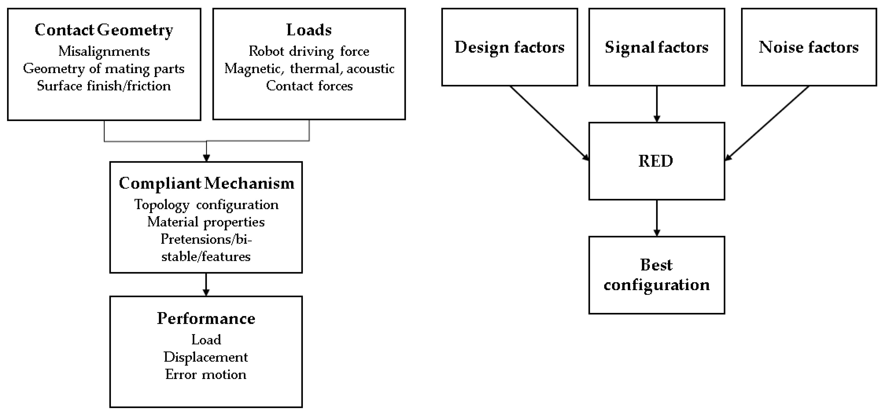
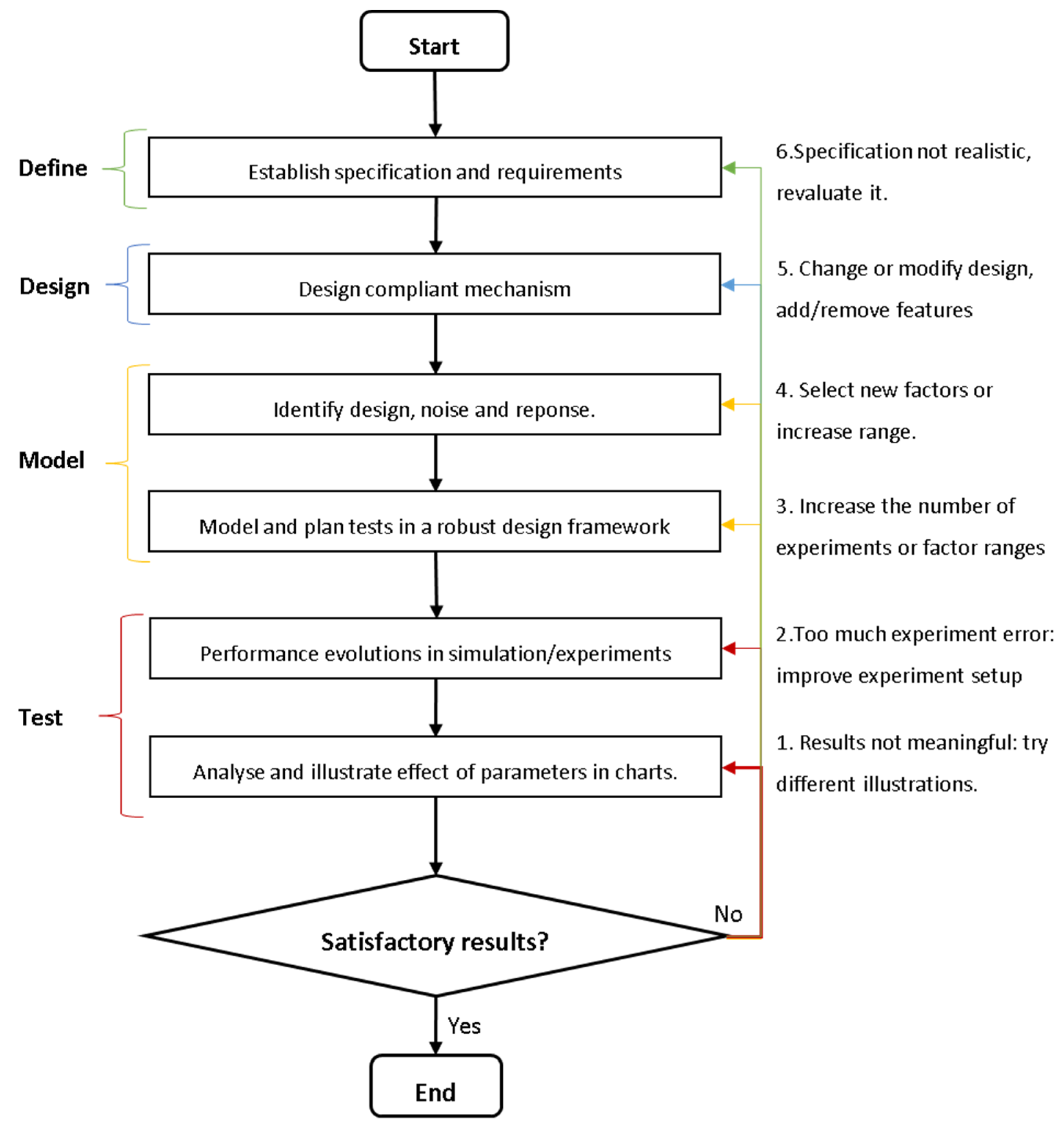
2.1. The Proposed Approach
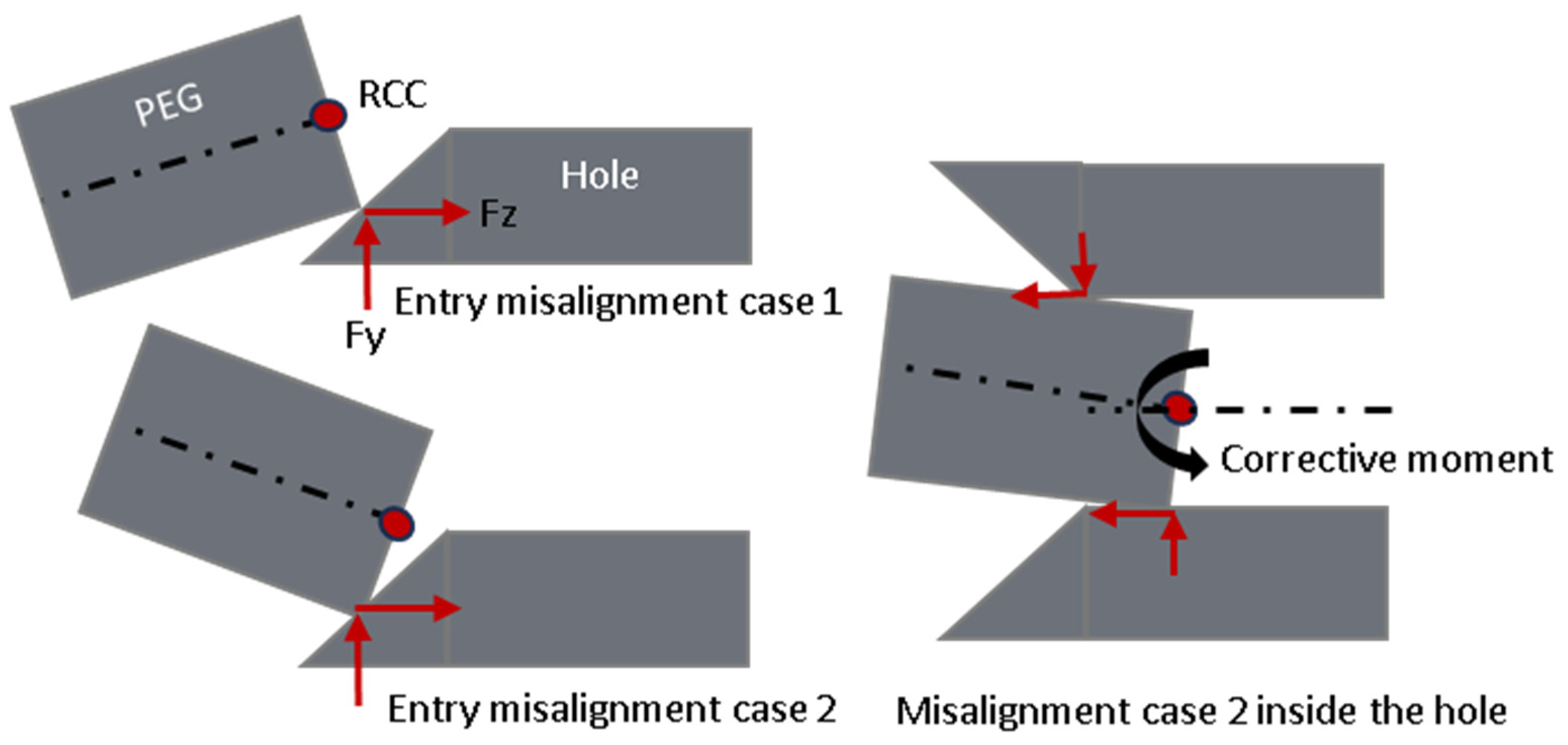
- Force regulation and accommodation:
- Load/displacement transfer:
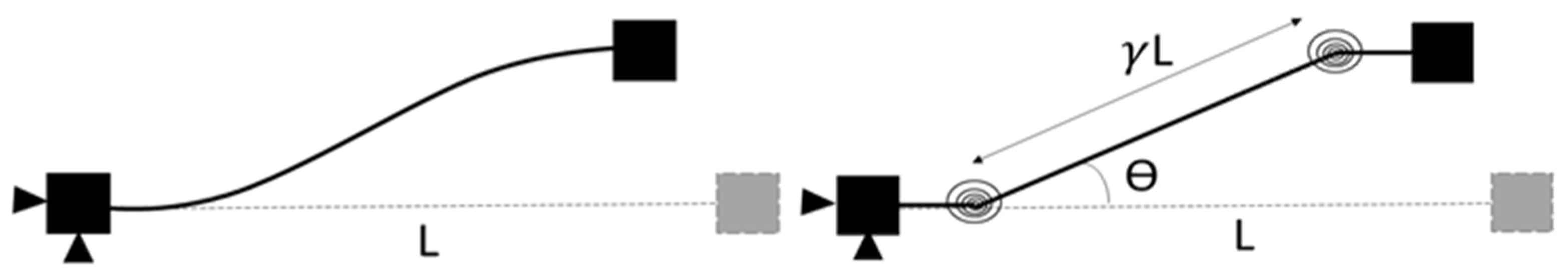
- Displacement function, path, or motion generation:
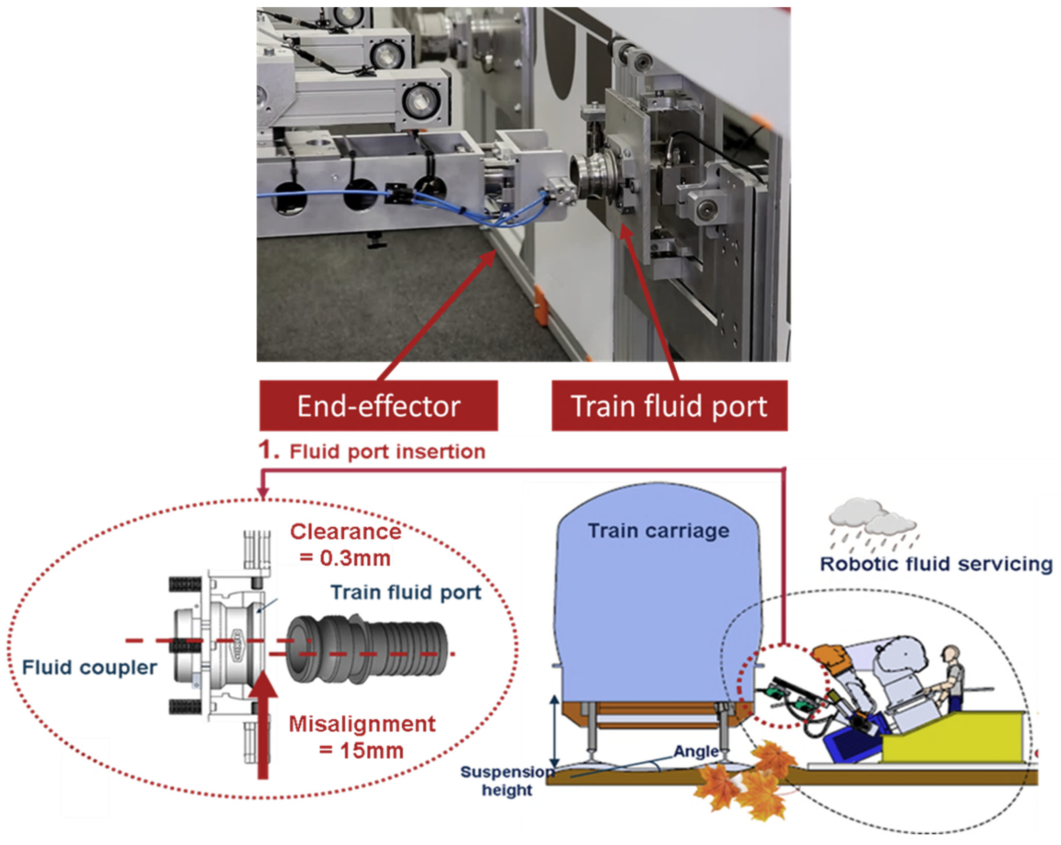
2.2. Case Study
2.2.1. Problem Definition
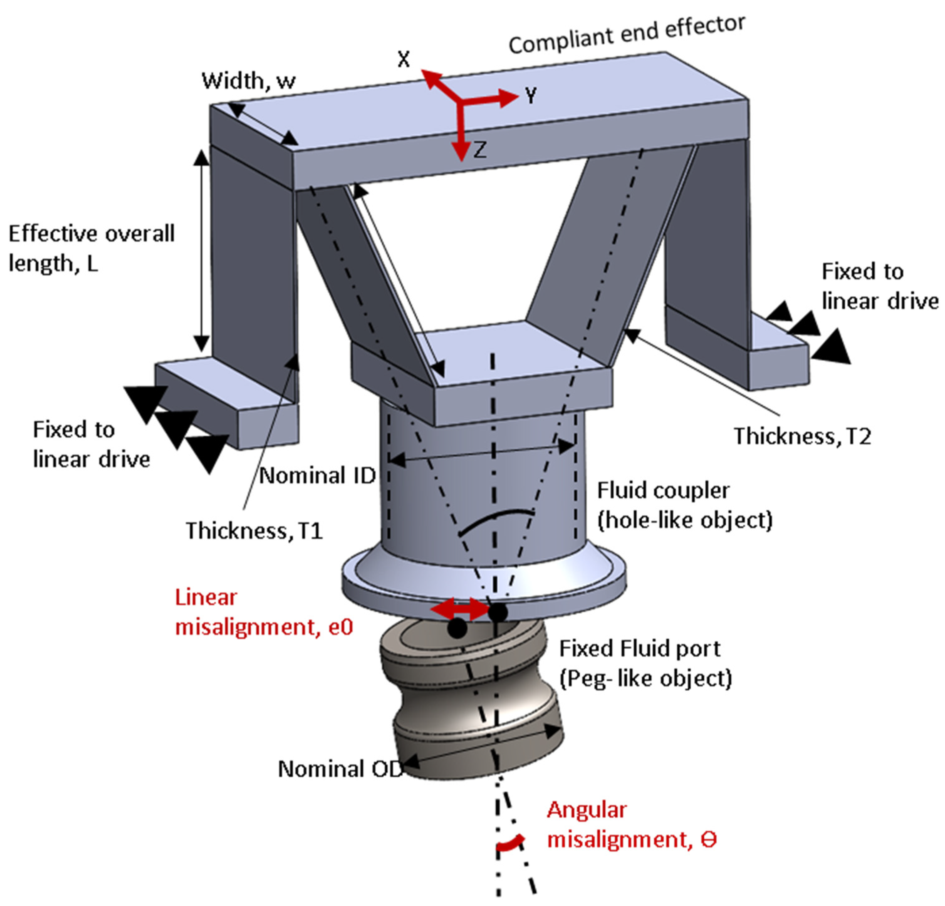
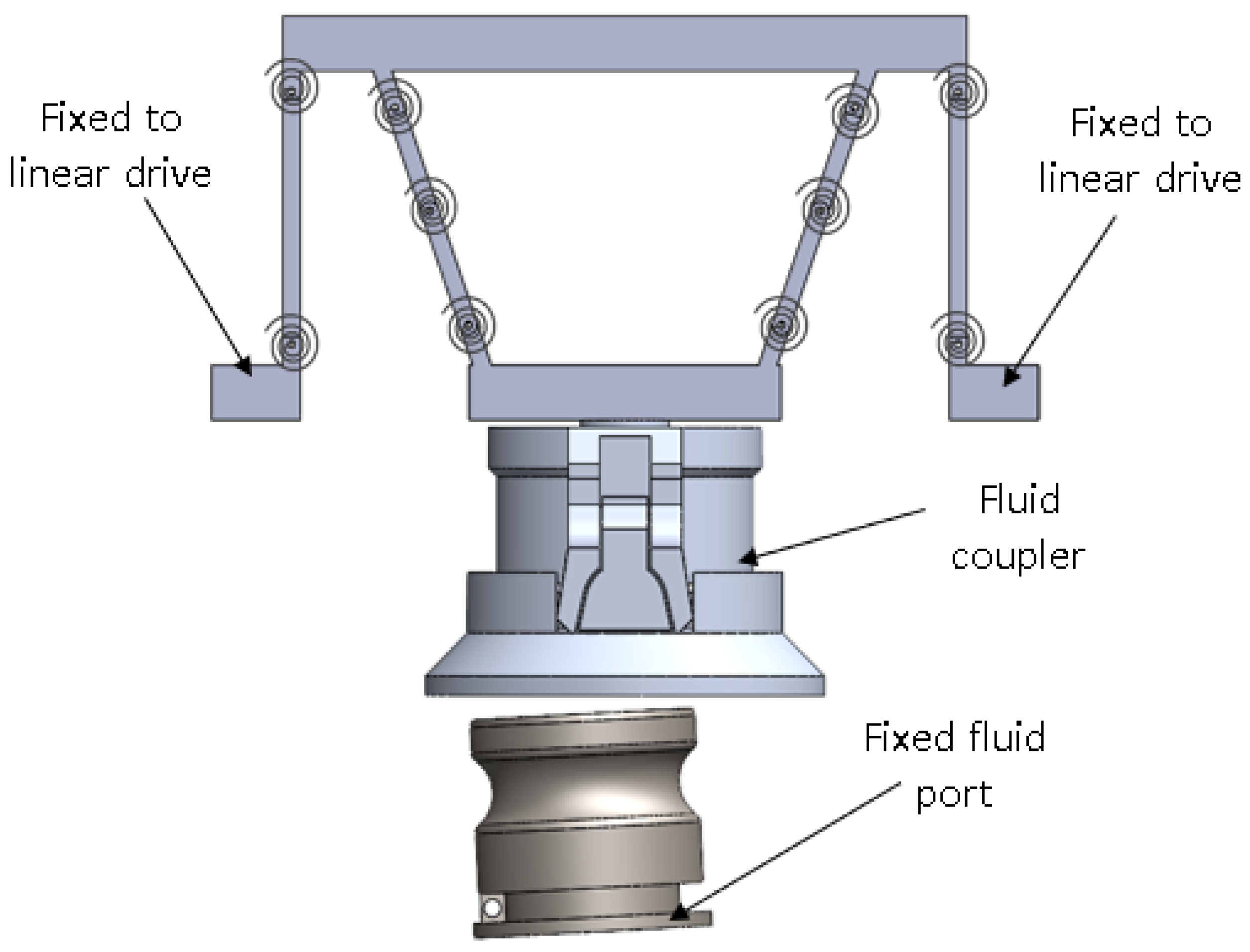
2.2.2. Design
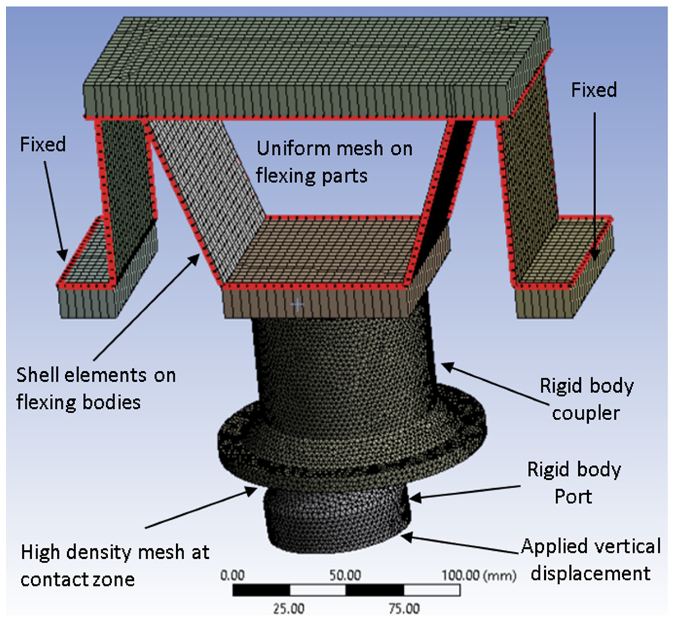
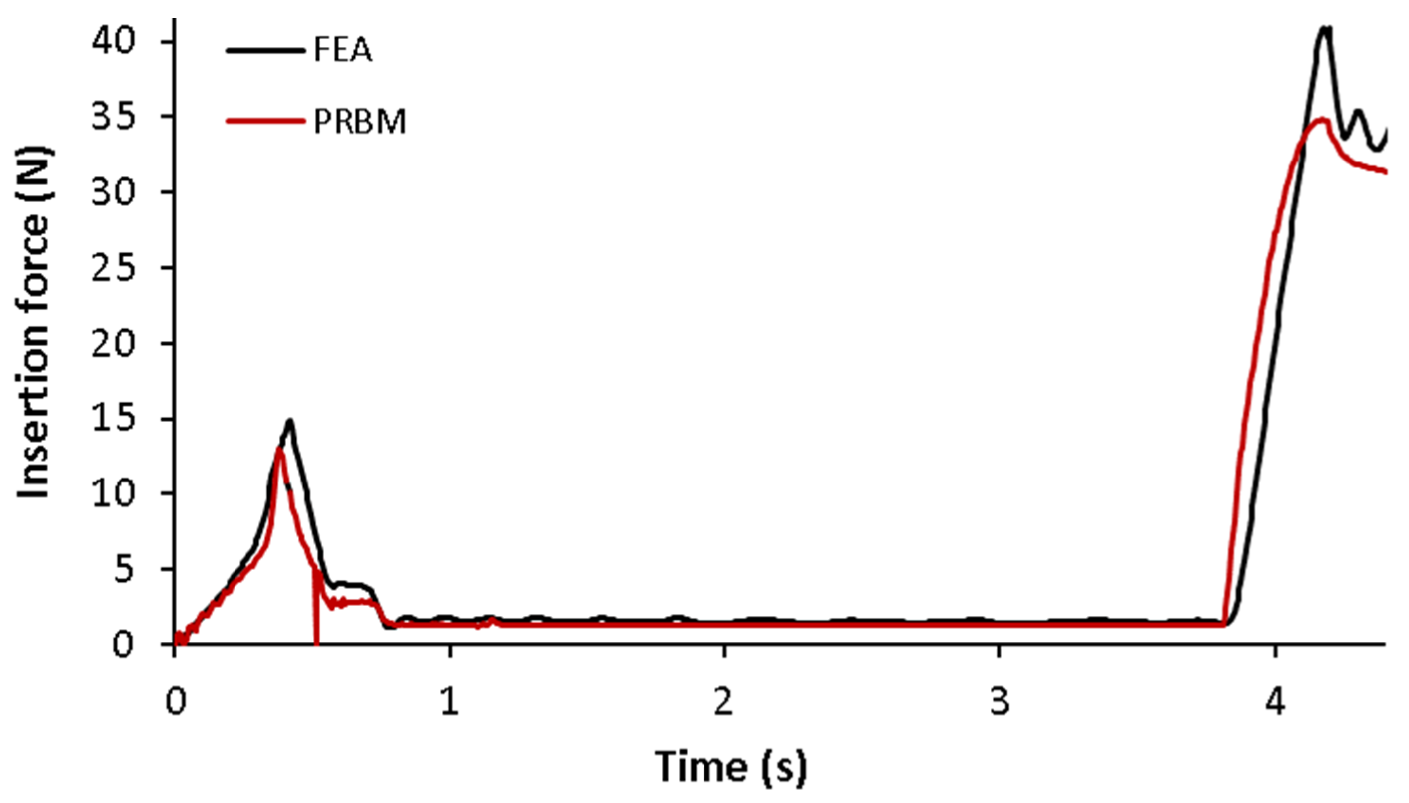
2.2.3. Modelling
- Linear motor: This is the robot arm which follows a linear path at a constant speed.
- Solid-body contacts: This is defined between the peg and the hole. We have found that increasing the stiffness and damping of the contact provides more accurate results; for fluid coupling we use 200,000 N/mm and 100 Ns/mm.
- Contact resolution is set to “precise contact”, with an integrator accuracy of 0.001 to ensure analytically sound results. The integrator used is WSTIFF, which responds better to abrupt changes (e.g., impact and contact separation).
- The number of frames per second is set to 50 for all insertions below 5 mm/s; for higher speeds, >5 mm/s and <15 mm/s, we use 100 FPS.
- SolidWorks motion analysis encourages no redundant DoFs, resulting from the mating of components to provide accurate force results. Redundant mates may be replaced with “bushings” with high stiffness, typically in the order of 10 × 107 N/mm. This stiffness is many orders of magnitude greater than the compliance of the mechanism, hence it will not induce noticeable error.
2.2.4. RED Plan
3. Results
4. Discussions and Conclusions
- Compliant robotics for autonomous train fluid servicing in a retrofittable manner;
- New standardised fluid port interfaces and adaptors for robot-friendly maintenance;
- New interfaces and compliant robotics for other tasks, e.g., shoe gear replacement;
- Robotic rolling stock manufacturing.
Author Contributions
Funding
Conflicts of Interest
References
- Rail Delivery Group. Long Term Passenger Rolling Stock Strategy for the Rail Industry; Rail Delivery Group: London, UK, 2018; Available online: https://www.raildeliverygroup.com/files/Publications/2018-03_long_term_passenger_rolling_stock_strategy_6th_ed.pdf (accessed on 23 October 2023).
- Hawkes, E.W.; Cutkosky, M.R. Design of Materials and Mechanisms for Responsive Robots. Annu. Rev. Control Robot. Auton. Syst. 2018, 1, 359–384. [Google Scholar] [CrossRef]
- Wang, T. Editorial Overview: Advances in Robotic Technologies. Engineering 2018, 4, 433–434. [Google Scholar] [CrossRef]
- Atherton, M.; Hill, S.; Harrison, D.; Ajovalasit, M. Economic and Technical Feasibility of a Robotic Autonomous System for Train Fluid Servicing. Proc. Inst. Mech. Eng. Part F J. Rail Rapid Transit 2020, 234, 338–350. [Google Scholar] [CrossRef]
- Eshraghi, K.; Jiang, P.; Suraci, D.; Atherton, M. Preliminary Study on End-Effector Compliance in Automated Fluid Coupling for Trains. In Proceedings of the Thirteenth International Tools and Methods of Competitive Engineering, Dublin, Ireland, 11–15 May 2020. [Google Scholar]
- Guastella, D.C.; Muscato, G. Learning-Based Methods of Perception and Navigation for Ground Vehicles in Unstructured Environments: A Review. Sensors 2020, 21, 73. [Google Scholar] [CrossRef] [PubMed]
- Hill, S.A.; Atherton, M.; Ajovalasit, M.; Harrison, D. Robust Automated Servicing of Passenger Trains-Fluids; Brunel University: Uxbridge, UK, 2017. [Google Scholar]
- Daniel, E. Whitney Mechanical Assemblies Their Design, Manufacture, and Role in Product Development; Oxford University Press: Oxford, UK, 2004. [Google Scholar]
- Jiang, J.; Bian, C.; Ke, Y. A New Method for Automatic Shaft-Hole Assembly of Aircraft Components. Assem. Autom. 2017, 37, 64–70. [Google Scholar] [CrossRef]
- Flores-Abad, A.; Ma, O.; Pham, K.; Ulrich, S. A Review of Space Robotics Technologies for On-Orbit Servicing. Prog. Aerosp. Sci. 2014, 68, 1–26. [Google Scholar] [CrossRef]
- Ogilvie, A.; Allport, J.; Hannah, M.; Lymer, J. Autonomous Satellite Servicing Using the Orbital Express Demonstration Manipulator System. In Proceedings of the 9th International Symposium on Artificial Intelligence, Robotics and Automation in Space, Beijing, China, 19–21 October 2020. [Google Scholar]
- Eshraghi, K.; Jiang, P.; Suraci, D.; Atherton, M. Preliminary Study of End-Effector Compliance for Reducing Insertion Force in Automated Fluid Coupling for Trains. JID 2020, 24, 139–161. [Google Scholar] [CrossRef]
- Xu, J.; Hou, Z.; Liu, Z.; Qiao, H. Compare Contact Model-Based Control and Contact Model-Free Learning: A Survey of Robotic Peg-in-Hole Assembly Strategies. arXiv 2019, arXiv:1904.05240. [Google Scholar]
- Wang, W.; Loh, R.N.; Gu, E.Y. Passive Compliance versus Active Compliance in Robotbased Automated Assembly Systems. Ind. Robot. 1998, 25, 48–57, ISSN 0143-991X. [Google Scholar] [CrossRef]
- Howell, L.L.; Olsen, B.M.; Spencer, P. Handbook of Compliant Mechanisms; Wiley: Hoboken, NJ, USA, 2013. [Google Scholar]
- Whitney, D.E. Quasi-Static Assembly of Compliantly Supported Rigid Parts. J. Dyn. Syst. Meas. Control 1982, 104, 65–77. [Google Scholar] [CrossRef]
- Whitney, D.E.; Rourke, J.M. Mechanical Behavior and Design Equations for Elastomer Shear Pad Remote Center Compliances. J. Dyn. Syst. Meas. Control 1986, 108, 223–232. [Google Scholar] [CrossRef]
- Zhao, Y.; Chen, K.; Yu, J.; Huang, S. Design of a Parallel Compliance Device with Variable Stiffness. Proc. Inst. Mech. Eng. Part C J. Mech. Eng. Sci. 2021, 235, 94–107. [Google Scholar] [CrossRef]
- Parvari Rad, F.; Vertechy, R.; Berselli, G.; Parenti-Castelli, V. Design and Stiffness Evaluation of a Compliant Joint with Parallel Architecture Realizing an Approximately Spherical Motion. Actuators 2018, 7, 20. [Google Scholar] [CrossRef]
- Ding, B.; Li, Y. Design and Analysis of a Decoupled XY Micro Compliant Parallel Manipulator. In Proceedings of the 2014 IEEE International Conference on Robotics and Biomimetics (ROBIO 2014), Bali, Indonesia, 5–10 December 2014; pp. 1898–1903. [Google Scholar]
- Dan, W.; Rui, F. Design and Nonlinear Analysis of a 6-DOF Compliant Parallel Manipulator with Spatial Beam Flexure Hinges. Precis. Eng. 2016, 45, 365–373. [Google Scholar] [CrossRef]
- Shintake, J.; Cacucciolo, V.; Floreano, D.; Shea, H. Soft Robotic Grippers. Adv. Mater. 2018, 30, 1707035. [Google Scholar] [CrossRef]
- Petković, D.; Pavlović, N.; Shamshirband, S.; Badrul Anuar, N. Development of a New Type of Passively Adaptive Compliant Gripper. Ind. Robot Int. J. 2013, 40, 610–623. [Google Scholar] [CrossRef]
- Sun, Y.; Liu, Y.; Pancheri, F.; Lueth, T.C. LARG: A Lightweight Robotic Gripper With 3-D Topology Optimized Adaptive Fingers. IEEE/ASME Trans. Mechatron. 2022, 27, 2026–2034. [Google Scholar] [CrossRef]
- Burgner-Kahrs, J.; Rucker, D.C.; Choset, H. Continuum Robots for Medical Applications: A Survey. IEEE Trans. Robot. 2015, 31, 1261–1280. [Google Scholar] [CrossRef]
- Noh, Y.; Han, S.; Gawenda, P.; Li, W.; Sareh, S.; Rhode, K. A Contact Force Sensor Based on S-Shaped Beams and Optoelectronic Sensors for Flexible Manipulators for Minimally Invasive Surgery (MIS). IEEE Sens. J. 2020, 20, 3487–3495. [Google Scholar] [CrossRef]
- Sanchez-Villamañan, M.D.C.; Gonzalez-Vargas, J.; Torricelli, D.; Moreno, J.C.; Pons, J.L. Compliant Lower Limb Exoskeletons: A Comprehensive Review on Mechanical Design Principles. J. NeuroEngineering. Rehabil. 2019, 16, 55. [Google Scholar] [CrossRef]
- Polygerinos, P.; Wang, Z.; Galloway, K.C.; Wood, R.J.; Walsh, C.J. Soft Robotic Glove for Combined Assistance and At-Home Rehabilitation. Robot. Auton. Syst. 2015, 73, 135–143. [Google Scholar] [CrossRef]
- Sturges, R.H.; Laowattana, S. Design of an Orthogonal Compliance for Polygonal Peg Insertion. J. Mech. Des. 1996, 118, 106–114. [Google Scholar] [CrossRef]
- Kamnik, R.; Rodič, G.; Mihelj, M.; Bajd, T. Automation of the Car Battery Lid Assembly Operation. Robot. Comput.-Integr. Manuf. 2001, 17, 435–446. [Google Scholar] [CrossRef]
- Jain, R.K.; Majumder, S.; Dutta, A. SCARA Based Peg-in-Hole Assembly Using Compliant IPMC Micro Gripper. Robot. Auton. Syst. 2013, 61, 297–311. [Google Scholar] [CrossRef]
- Southern, W.R.; Lyons, C.G. The Study of a Passive Accommodation Device in Robotic Insertion Processes. J. Mater. Process. Technol. 2002, 124, 261–266. [Google Scholar] [CrossRef]
- Atherton, M.A.; Bates, R.A. Robust Optimization of Cardiovascular Stents: A Comparison of Methods. Eng. Optim. 2004, 36, 207–217. [Google Scholar] [CrossRef]
- Dean, A.; Voss, D. Design and Analysis of Experiments; Wiley: Hoboken, NJ, USA, 2012. [Google Scholar]
- Arvidsson, M.; Gremyr, I. Principles of Robust Design Methodology. Qual. Reliab. Engng. Int. 2008, 24, 23–35. [Google Scholar] [CrossRef]
- Eppinger, S.D.; Ulrich, K. Product Design and Devolopment, 6th ed.; McGraw Hill: New York, NY, USA, 2015. [Google Scholar]
- Zong, G.; Pei, X.; Yu, J.; Bi, S. Classification and Type Synthesis of 1-DOF Remote Center of Motion Mechanisms. Mech. Mach. Theory 2008, 43, 1585–1595. [Google Scholar] [CrossRef]
- Chen, G.; Xiong, B.; Huang, X. Finding the Optimal Characteristic Parameters for 3R Pseudo-Rigid-Body Model Using an Improved Particle Swarm Optimizer. Precis. Eng. 2011, 35, 505–511. [Google Scholar] [CrossRef]


| Source of Misalignment | Linear (+/− mm) | Angular (+/− deg) |
|---|---|---|
| Inaccuracy of robot mechanical movement | 1 | 0.5 |
| Inaccuracy of robot positioning relative to train | 1 | 0.5 |
| Unintentional dimensional, i.e., due to wear tolerances | 3 | 1 |
| Train suspension motion, e.g., due to wear or load | 10 | 3 |
| Sum of misalignments | 15 | 5 |
| Statement | Description |
|---|---|
| Project | 1. Compliant end-effector for coupling of hoses in train fluid servicing. |
| Benefit | 1. Reduced cost and requirements on the robot side, i.e., a less complicated system with reduced degrees-of-freedom (DoFs) and payload. 2. Reduced operational forces for reduced health and safety risks. |
| Goal | 1. End-effector designs with misalignment range of +/15 mm linear, 5 deg angular. 2. Reduce operating forces, to 150 N. 3. Incorporate compliant mechanisms to take advantage of their inherent benefits (i.e., costs). |
| Assumptions | 1. Robot is a Cartesian system like the CyberFluids system. 2. Dixon fluid ports are used in the end-effector, and train fluid ports are standardised using adapters. |
| Experiment Variable | Symbol | Model Comparison Study | RED Study | Units |
|---|---|---|---|---|
| Overall length | L | 0.9 | 0.7 to 0.11 | N/mm |
| Thickness ratio | T2/T1 | 1.2 | 1.2 to 1.5 | - |
| Linear misalignment | e0 | 5 | 5 to 15 | mm |
| Angular misalignment | Ѳ | 4 | −5 to 5 | deg |
| Thickness | T1 | 2 | 2 | mm |
| Friction coefficient | F | 0.2 | 0.15 | - |
| Nominal ID | ID | 63 | 63 | mm |
| Nominal OD | OD | 63.85 | 63.85 | mm |
| Insertion speed | V | 5 | 10 | mm/s |
| Elastic modulus | E | 3 | 2.6 | GPa |
| e0 | 1 | 1 | 0 | 0 | |||||
| Ѳ | 1 | 0 | 1 | 0 | |||||
| Config # | L | T2/T1 | Y1 | Y2 | Y3 | Y4 | S/N | ||
| 1 | 1 | 1 | 91 | 116 | 100 | 107.5 | 103.63 | 10.66 | −35.01 |
| 2 | 1 | 0 | 103 | 69 | 54.5 | 61 | 71.88 | 21.58 | −32.85 |
| 3 | 0 | 1 | 243 | 315 | 250.5 | 281 | 272.38 | 32.83 | −42.73 |
| 4 | 0 | 0 | 255 | 237 | 152 | 178 | 205.50 | 48.51 | −42.21 |
Disclaimer/Publisher’s Note: The statements, opinions and data contained in all publications are solely those of the individual author(s) and contributor(s) and not of MDPI and/or the editor(s). MDPI and/or the editor(s) disclaim responsibility for any injury to people or property resulting from any ideas, methods, instructions or products referred to in the content. |
© 2023 by the authors. Licensee MDPI, Basel, Switzerland. This article is an open access article distributed under the terms and conditions of the Creative Commons Attribution (CC BY) license (https://creativecommons.org/licenses/by/4.0/).
Share and Cite
Eshraghi, K.; Wang, M.; Mares, C. Towards Robust and Effective Passive Compliance Design of End-Effectors for Robotic Train Fluid Servicing. Machines 2023, 11, 997. https://doi.org/10.3390/machines11110997
Eshraghi K, Wang M, Mares C. Towards Robust and Effective Passive Compliance Design of End-Effectors for Robotic Train Fluid Servicing. Machines. 2023; 11(11):997. https://doi.org/10.3390/machines11110997
Chicago/Turabian StyleEshraghi, Kourosh, Mingfeng Wang, and Cristinel Mares. 2023. "Towards Robust and Effective Passive Compliance Design of End-Effectors for Robotic Train Fluid Servicing" Machines 11, no. 11: 997. https://doi.org/10.3390/machines11110997