1. Introduction
The automotive industry (AI) is one of the main pillars of the world economy, being responsible for a large number of direct and indirect jobs [
1,
2]. Although, in recent decades, several brands have been grouped together, the competition between them has been fierce for a long time [
3,
4]. Each group tries to survive based on meeting market expectations, through strong innovation and extremely high competitiveness [
5,
6]. It is this same competitiveness that is transmitted to the entire supply chain, e.g., the component manufacturers [
7,
8]. Due to AI, numerous techniques for the optimization of resource management have been developed, such as lean manufacturing [
9,
10,
11,
12] and automation [
13,
14,
15,
16,
17]. In fact, automation has made it possible to move from a serial production paradigm with almost zero model variability (Ford theory) to a much more personalized and flexible mode of production [
18,
19]. Device programming and information integration have evolved significantly, and the fourth and fifth industrial revolutions are already strongly rooted in original equipment manufacturers (OEMs), tending to extend to all component manufacturers, under the penalty of being excluded from this position [
20,
21,
22]. The challenges posed in AI now include high flexibility, which translates into the ability to assemble different types of vehicle models on the same line without any type of setup [
23], and the same applies to component manufacturers, where vehicle customization implies a greater diversity of components, which requires a strong reduction or even the elimination of setups [
24,
25]. It is in this context that academia has carried out several studies with a view to developing frameworks and theories that, applied in case studies, have been validated and significant advances have been achieved in terms of increasing competitiveness in this sector [
26,
27,
28,
29]. Below, some of these efforts will be described, mainly related to the automotive industry and Bowden cables, which are in line with the study now presented and which demonstrate how the development of flexible automation has contributed to a strong increase in production flexibility, without this being directly reflected in the costs, allowing competitiveness to remain high [
30,
31,
32].
The main motivation for carrying out this work arose from the need to make the manufacture of Bowden cables more competitive, as well as incorporating the need for new features in the product that are beginning to be a standard in the requirements of car manufacturing OEMs. Therefore, it was necessary to incorporate new operations into a single piece of equipment, whilst simultaneously promoting greater flexibility when switching from one product to another. The project’s aims were also to reduce as much as possible the space occupied by the new equipment, and that the construction cost was limited to a previously established value.
The pertinence of the present study can be easily explained by the number of studies related to the production of Bowden cables described above, and by the sequence of innovations that the process has undergone, continuously improving its competitiveness in the market and providing new mechanical solutions able to be applied in several other production systems. The objective of this work was to increase the flexibility and productivity of equipment capable of producing the first subset that constitutes the product commonly known as the Bowden cable. No standard solutions were found on the market that were sufficiently effective to overcome the processing difficulties experienced. Taking into account that the Bowden cable market increasingly requires the use of coated cables, and this implies stripping operations included in its manufacturing process, the main novelty of this work consists of designing a new wire fixation system, as well as a new rotating system integrated in the middle of the process, saving a great deal of space and giving the desired flexibility and productivity to the manufacturing system. Moreover, the new production system integrates several operations usually carried out for the manufacture of the referred subset, creating a new production strategy through new mechanical and automatic solutions, thus reducing logistics operations and manual work, increasing operator safety, and increasing the production rate and flexibility of the equipment, by reducing the setup time.
2. State of the Art
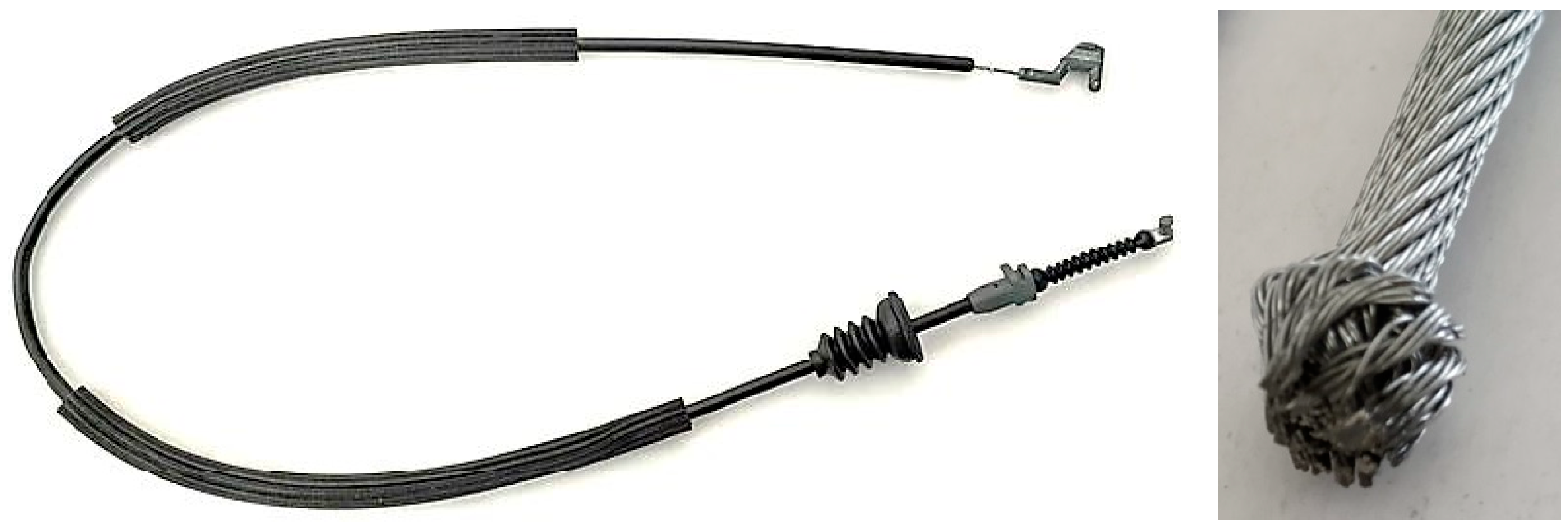
Bowden cables (
Figure 1) are a complex product, consisting of a flexible metallic cable (conduit), provided with two metallic terminals, covered with a polymer layer or not, and conveniently insulated to be mounted inside the car [
33]. Indeed, Bowden cables allow the transmission of mechanical actions that passengers wish to produce in another area of the vehicle. This transmission of force must be carried out in a sophisticated way, following complex paths through the vehicle (opening doors, opening the fuel filler cap, opening the hood, raising and lowering the windows, etc.). However, these products present low added value, involving a large number of small operations, which complicates their manufacturing sequences. In fact, the manufacture of these components involves many processes, such as cutting metallic cables, stripping the coating, injecting terminals in Zamak in two stages, assembling plastic parts like foam tubes, laying coated spiral tubes and injecting polymers (grommets) to complete the process. Furthermore, the flexibility of the product brings further challenges when its length is longer.
The problems brought by the elevated flexibility were addressed by Vieira et al. [
34], who developed a new support system for the transport of Bowden cables during the production process, eliminating uncertainties in terms of size due to the bending of the semi-product (conduit) during the production process. This new concept was successfully put into practice, fully resolving the quality problems that were jeopardizing the overall equipment effectiveness (OEE). The quality of the metallic cable that underlies the effect produced by Bowden cables (power transmission through complex layouts) was also studied by Pinto et al. [
35], verifying that the storage conditions of this cable are critical for the preservation of the proper functioning of these components inside the automobile. Precisely to eliminate corrosion problems in operation, with the respective consequences for the force that the user needs to exert to perform a certain action, Ribeiro et al. [
36] developed an integrated grease injection system between the wire rope and the spiral tube, which aimed to significantly improve productivity, namely via the ergonomics of the workers in this function, ensuring a reduction in grease waste as well, thus increasing the economic and environmental sustainability of the process [
37]. The Zamak terminals injected at the ends of the metallic cable, where the force is in fact exerted, are equally important, since this process involves the injection of a light alloy, in a very small amount, with a very high speed, and it requires that the complete filling of the mold is achieved. Otherwise, the force exerted could break the injected terminal, since its displacement is almost impossible due to the fact that a mushroom is created at each end of the cable (
Figure 1), which is inside the injected terminal, ensuring that the force exerted on it does not cause the terminal to slip on the wire rope. Pinto et al. [
38,
39] studied, through simulation, the positioning of the feed channels, vents and metal flow inside the mold, avoiding the formation of pores in the injected terminals, since this problem is known to exist. Later, Pereira et al. [
40] studied this problem again, recommending changes to the molds and their structure, as well as to the auxiliary equipment, with a view to increasing the efficiency of the process.
The Bowden cable’s manufacturing and assembly process has also been the subject of several studies, with a view to integrating processes. In fact, the required diversity of processes brings added challenges in terms of internal logistics [
41] and causes delays in the lead time of the process, as it causes the unnecessary waste of time and delays between processes [
42], since the diversity of the processes and equipment involved prevents the process from being carried out in an integrated manner.
An initial approach was carried out by Moreira et al. [
42]. These authors developed a new concept of equipment that started from the metallic cable and transported it along the layout of the equipment, performing successive operations on it, in the appropriate sequence, providing an essentially complete product at the end of the process. The concept was very innovative at the time, having been successfully put into practice and allowing for large productivity gains, eliminating numerous internal logistics operations that were necessary until then, including intermediate counts, intermediate control posts, etc. This development represented a significant advance in terms of concept, demonstrating that there was room for progress. However, the cable, which, until then, was not coated, due to the aforementioned corrosion problems, then contained a polymeric coating, as required by customers who wanted to increase the quality of the product and ensure a longer useful life for the component. This new requirement from customers demanded new development efforts, with the need to introduce a new intermediate workstation capable of stripping the coated cable, before it was sent to the workstation to create the mushroom, and the subsequent injection of Zamak. In this context, the work presented by Figueiredo et al. [
43] successfully reconfigured the equipment to include a workstation capable of effectively executing this interim operation. However, this concept was not yet complete, as the equipment was not capable of automatically performing the second injection of Zamak, which ends the cable, after it is essentially complete. Thus, Sousa et al. [
44] developed a new concept that extended the capabilities of the previously developed equipment, allowing, in the same sequence, the equipment to include a second Zamak injection machine, which allowed the closure of the production cycle and defined the cable as complete. This study made it possible to proceed with the complete integration of all processes inherent in the production of Bowden cables, eliminating intermediate stock and logistical operations that did not add any value. The material is fed automatically to the equipment, which, through different workstations, and step by step, adds different components to the Bowden cable, until it is complete. In addition, the overall energy consumption is lower; maintenance is more concentrated, not being distributed across several pieces of equipment; labor is significantly reduced; intermediate stocks are eliminated; and the equipment can be connected to a centralized information system. Thus, it can be stated that this type of equipment follows the principles of Industry 4.0 [
45]. It should also be noted that these systems have high flexibility through programming, allowing the production of different references almost always without setup, or with very small setups, which can be easily diluted in small production series, without affecting the competitiveness of the product. Obviously, robotics could be applied to solve some of these problems, but the space occupied, the initial cost, maintenance difficulties and the need for several peripheral devices make this path more difficult to adopt and less profitable, affecting the product’s competitiveness [
46,
47,
48,
49,
50].
Industry 4.0 and automation within production sectors in the automotive industry have also been addressed by many researchers. Gazová et al. [
51] studied the effect of Business Process Management on the level of automation and technologies related to Industry 4.0, pointing out that BPM is positively affecting and increasing the level of automation and new technologies involved in Industry 4.0 implementation. A similar study developed by Papulová et al. [
15] concluded that there is a high frequency of use of sensors, programmable devices such as PLC/HMI and industrial robots, with a view to approaching the concepts of Industry 4.0, and that large manufacturing companies implement automation elements at a more advanced level than medium and small-sized businesses. On the other hand, Cavone et al. [
52] successfully used hybrid Petri nets to redesign low-automated production processes, more easily detecting bottlenecks and waste sources. The problem of zero defects, which is desired when the Industry 4.0 paradigm is implemented in the automotive industry, was also studied by Cavone et al. [
53], demonstrating that model predictive control can be a valuable aid in achieving this objective.
Observing the works previously described, it is clear that the main trend is to increase the degree of automation of production systems used in the automotive industry, creating more effective, integrated and flexible systems capable of avoiding the generation of defective products, thus contributing to compliance with the requirements established by the Industry 4.0 principles. Thus, the main concerns in this work were to create an integrated, highly productive, extremely flexible, low-cost production system that occupied the smallest possible area on the factory floor and guaranteed the maximum quality of the products manufactured.
3. Methodology, Product Definition, Current Process and Strategy
3.1. Methodology Followed
Because the product had already been produced, and this work essentially aimed to develop new methodologies capable of improving the processes through proper integration, it was considered feasible to adopt the design science research (DSR) methodology. In fact, this methodology was developed essentially to allow improvements to be introduced in processes or to develop new products from existing ones, and it can also be applied in other types of situations [
54,
55,
56,
57,
58]. Regarding the DSR methodology, Teixeira et al. [
59] state that it is particularly useful due to its “technological background and its focus on developing models and methods that address complex and ill-defined problems”. Under a continuous improvement context, Siedhoff [
60] described a new arrangement of nominal processes for the DSR methodology based on the work of Devitt and Robbins [
61], which can be implemented after overall problem identification, merging design thinking with pre-existing DSR phases. This can include research activities, as well as the cycle principle [
62]. The process comprises a stage of exploration (problem clarification/definition and solution establishment) and prescriptive investigation, which, as shown by Peffers et al. [
62] and Lepenioti et al. [
63], are solution recommendations that lead to optimal decision making ahead of time. In fact, the DSR methodology, applied by Siedhoff [
60] and Tojal et al. [
64] to processes related to automotive component production, such as the wire bending process used for the production of car seat cushions, has shown excellent results, proving that this methodology can be easily and beneficially applied in the current development context. The different stages of this methodology are shown in
Table 1.
3.2. Product
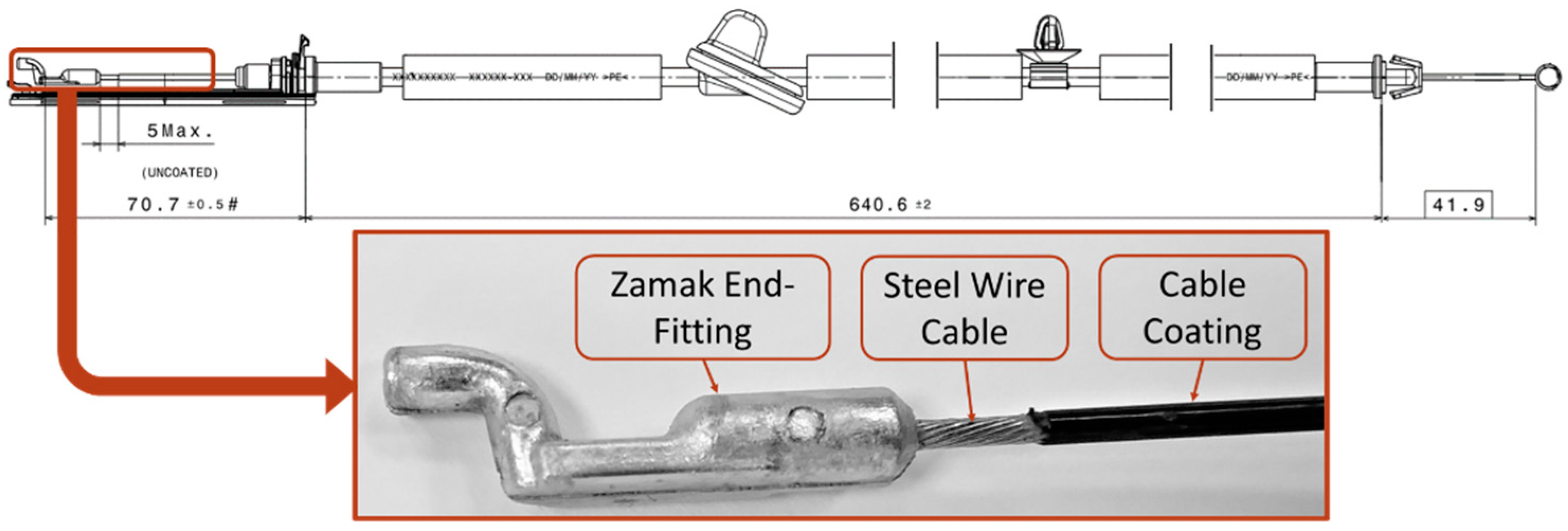
The development of the new equipment concept stems from the need to improve the competitiveness in the manufacture of Bowden cables. These cables, in their construction, have a wide variety of components, but, for the case under analysis, the intention is essentially to analyze the cable subset highlighted in
Figure 2. The cable subset is composed of two main components: the coated or uncoated wire rope (steel wire cable) and the first cable Zamak end-fitting. In the case of this project, the cable subset consists of a polyamide-coated wire rope with the first terminal injected in Zamak.
3.3. Identification of Process Problems and Design of Possible Solutions
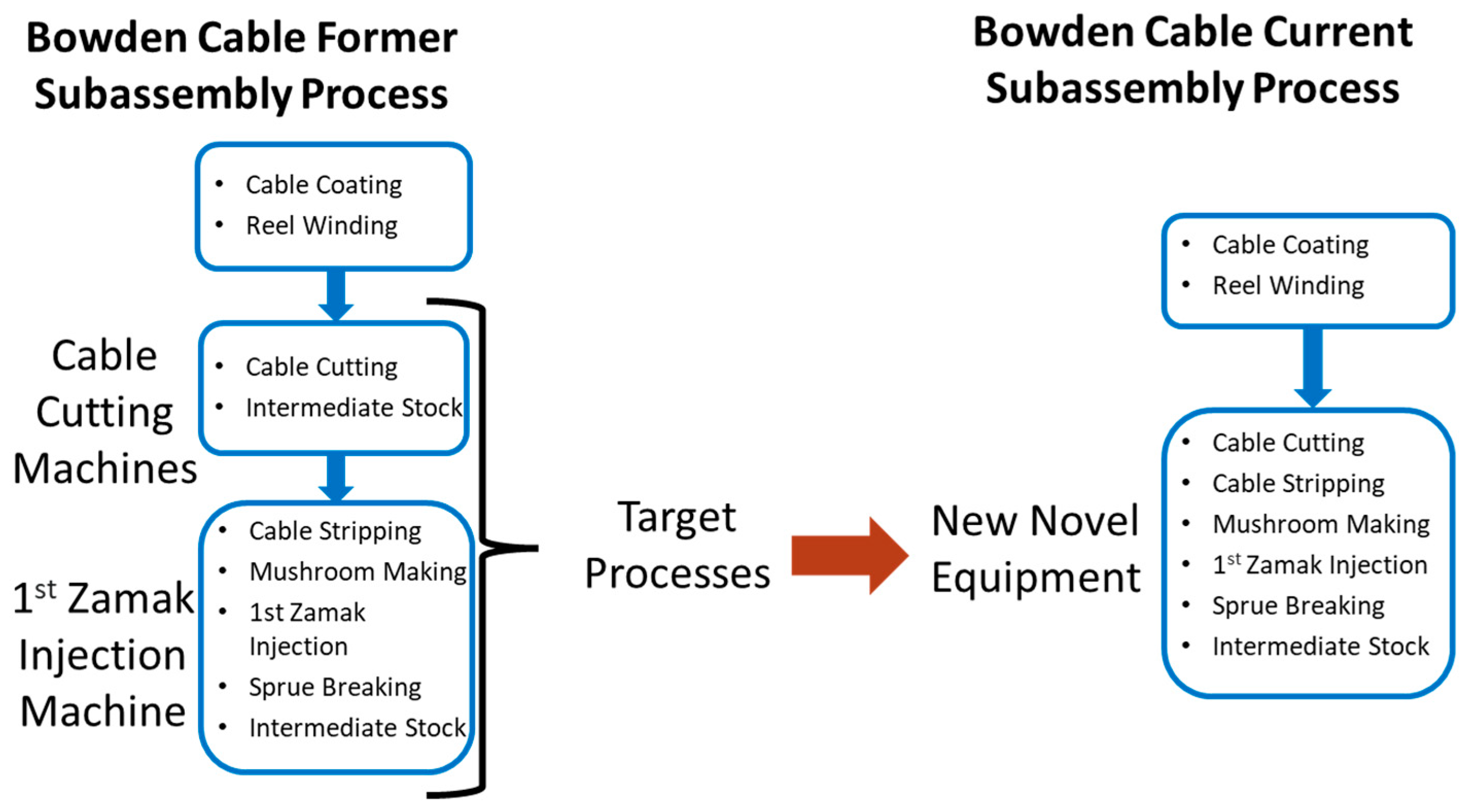
Despite the few constituents of the subset, the manufacturing process required to obtain it involves several steps. The manufacturing processes used follow the subsequent sequence: (1) cable cutting; (2) stripping of the cable end according to the terminal to be used; (3) realization of the mushroom; (4) injection of the Zamak terminal; and, finally, (5) breakage of the sprue. The current process is divided into dedicated cutting equipment and manual Zamak injection machines, as seen in the left column of
Figure 3 (Cutting Equipment and Manual 1st Injection Machines). Thus, the strategy of this work is to cluster processes into automatic equipment, through the development of new tools and compact manipulators that work together, carrying out the operations described above but in such a way that they are in line with the process column on the right side of
Figure 3.
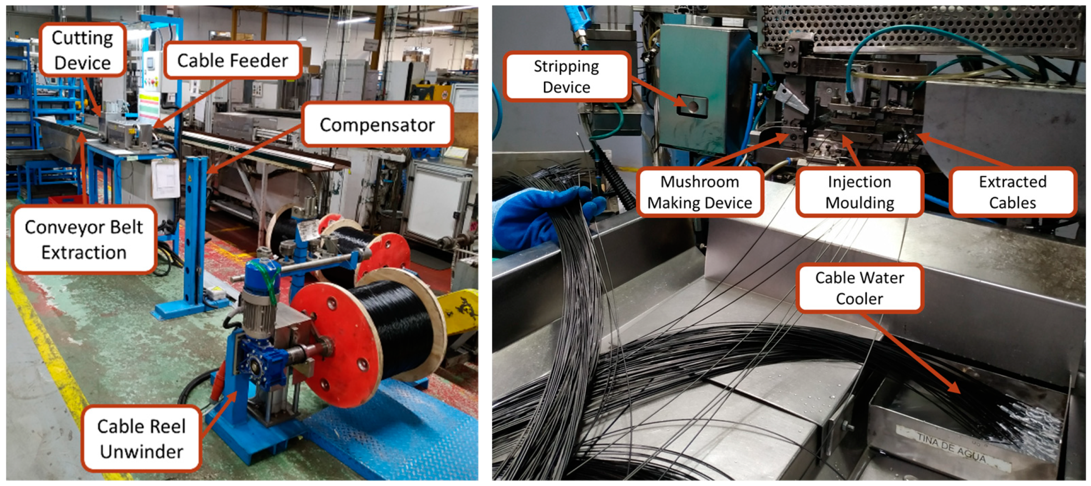
Currently, the manufacture of cable subsets is carried out by two individual pieces of equipment, one that only cuts the cable and other responsible for the manual Zamak injection, with the last one incorporating the stripping operation, mushroom creation and injection of the Zamak terminal. As the name implies, cutting machines only carry out this operation, while, in manual injection machines, the operator is responsible for placing the cables in the stripping device and then in the device to create the mushroom, and for then positioning this part of the cable in the mold where the Zamak terminal will be injected. After injection, the operator still needs to place a small batch of cables in a tub of water to cool them down. These stages can be seen in
Figure 4.
To enable process integration, it is necessary to review the devices already used in the previous process, identifying the problems. This work corresponds to the first phase of the DSR methodology, as previously described. All devices proven to work in the previous concept will be adopted and eventually improved, integrating the new equipment concept. The devices responsible for the integration and some specific tasks will be developed and designed from scratch. In fact, several standard solutions on the market for some operations were analyzed, namely the CrimpCenter (Schleuniger, Thun, Switzerland) equipment manufactured by Schleuniger for the stripping operation, among others. However, these solutions do not constitute an alternative, as they cannot be integrated into a single equipment concept, also presenting problems such as too much space required for their operation. Indeed, due to the specificities of this type of product and the wide variety of manufacturing processes involved, this equipment is usually developed by the companies that need it.
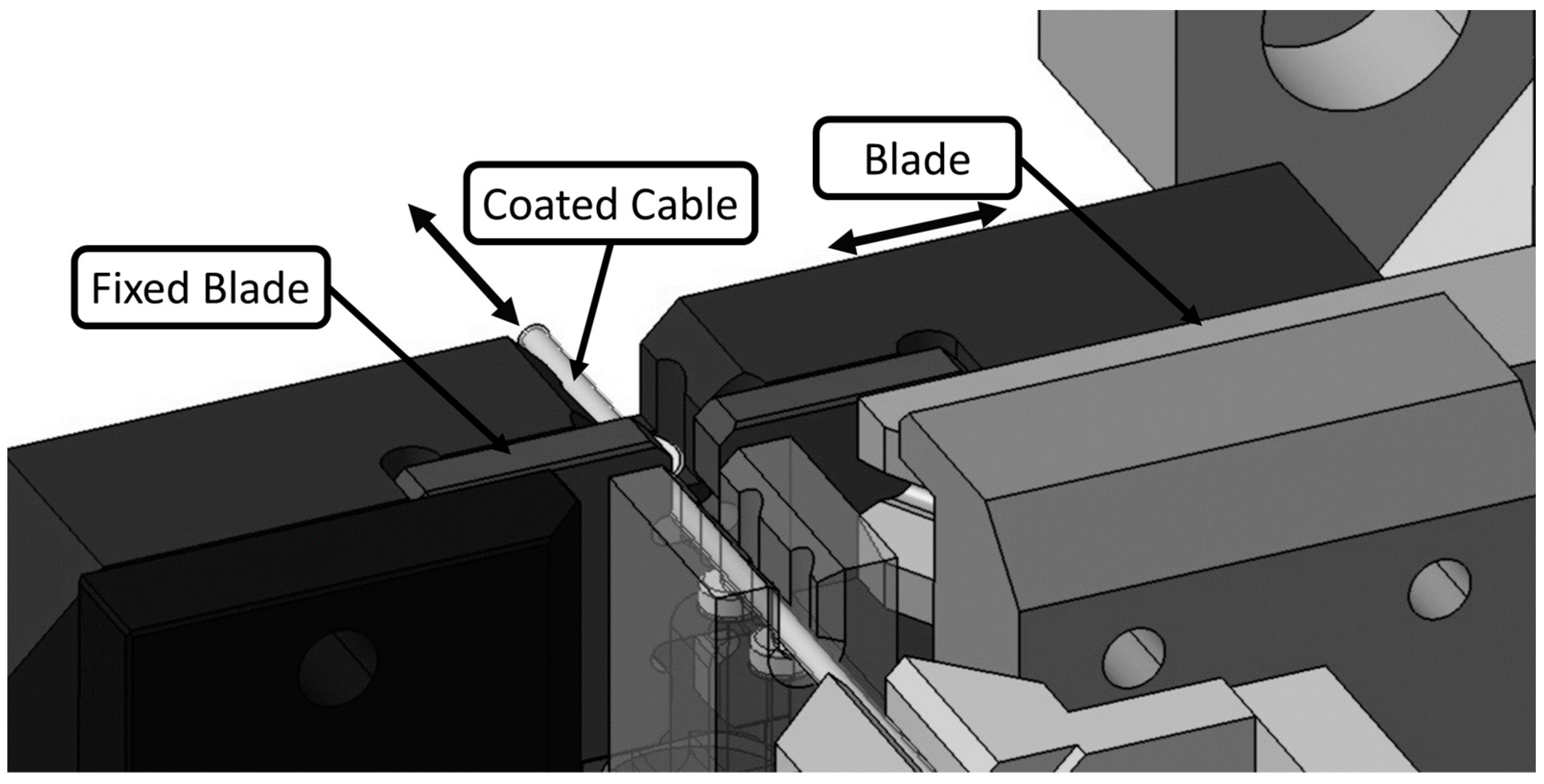
As the cable is coated, it is cut mechanically using cutting blades. In this system, shown in
Figure 5, the cable passes through a fixed counter-blade, where it is guided through a hole slightly larger than the outside diameter of the cable. The mobile blade, moving towards the handle, makes the cut.
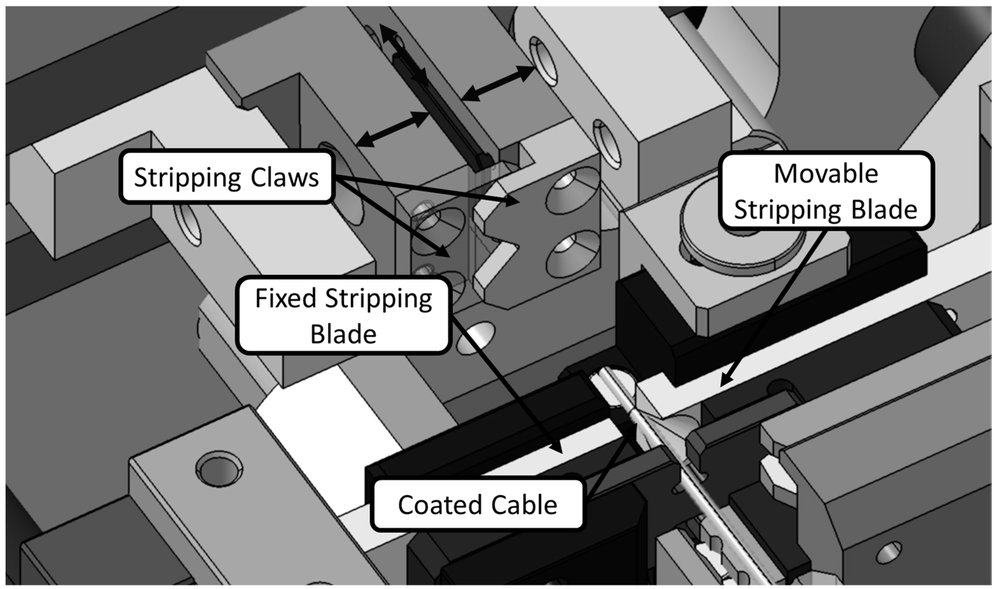
Stripping devices usually do not allow the passage of cables, as depicted in the example shown in
Figure 6. This proves to be an important detail for the development of the new concept, which will lead to the need to develop a completely new stripping device. In this device there are two stripping blades, which are positioned face to face and cut the coating without damaging the metallic filaments of the wire rope. This is possible since their cutting hole has the same diameter as the metallic cable. Moreover, because they are in guided movement and facing each other, they act as a movement limiter for each other. These development activities are already part of the second stage of the DSR methodology.
The other part of the device that needs to be modified is the set of stripping jaws. These jaws grip the cable and extract the stripped coating tip after the stripping blades have closed. In this case, it was necessary to develop a concept of stripping claws capable of not only allowing the cable to pass through them but also guiding its path.
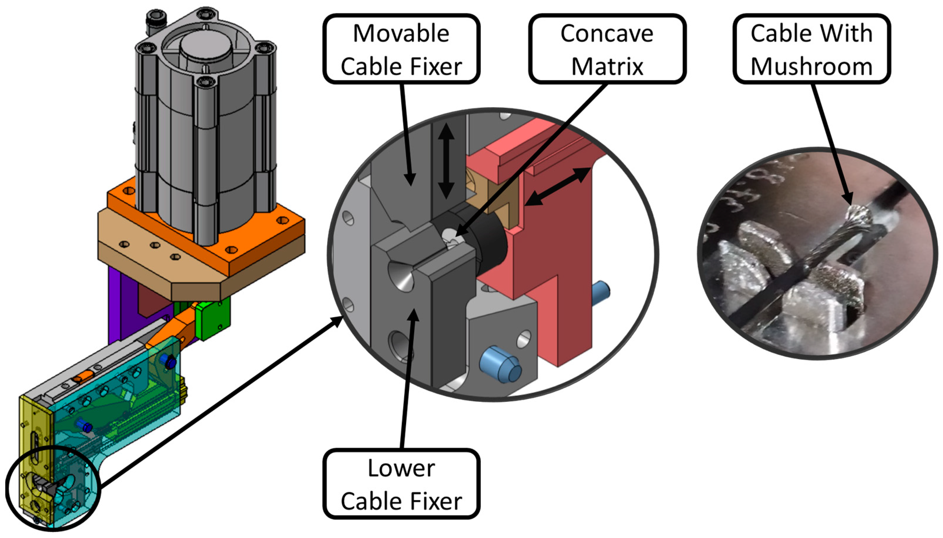
After being cut and stripped, the wire rope (metallic cable) is introduced into the mushroom making device. This device, presented in
Figure 7, is standard, and the idea is to keep it unchanged, since it is an integral part of the Zamak injection machines that are intended to be used, and the company already has fasteners and mushroom matrices for existing wire ropes. In this device, when the wire rope is introduced, it is pressed by the fasteners and the matrix frontally crashes the cable, producing the mushroom by impact and plastic deformation.
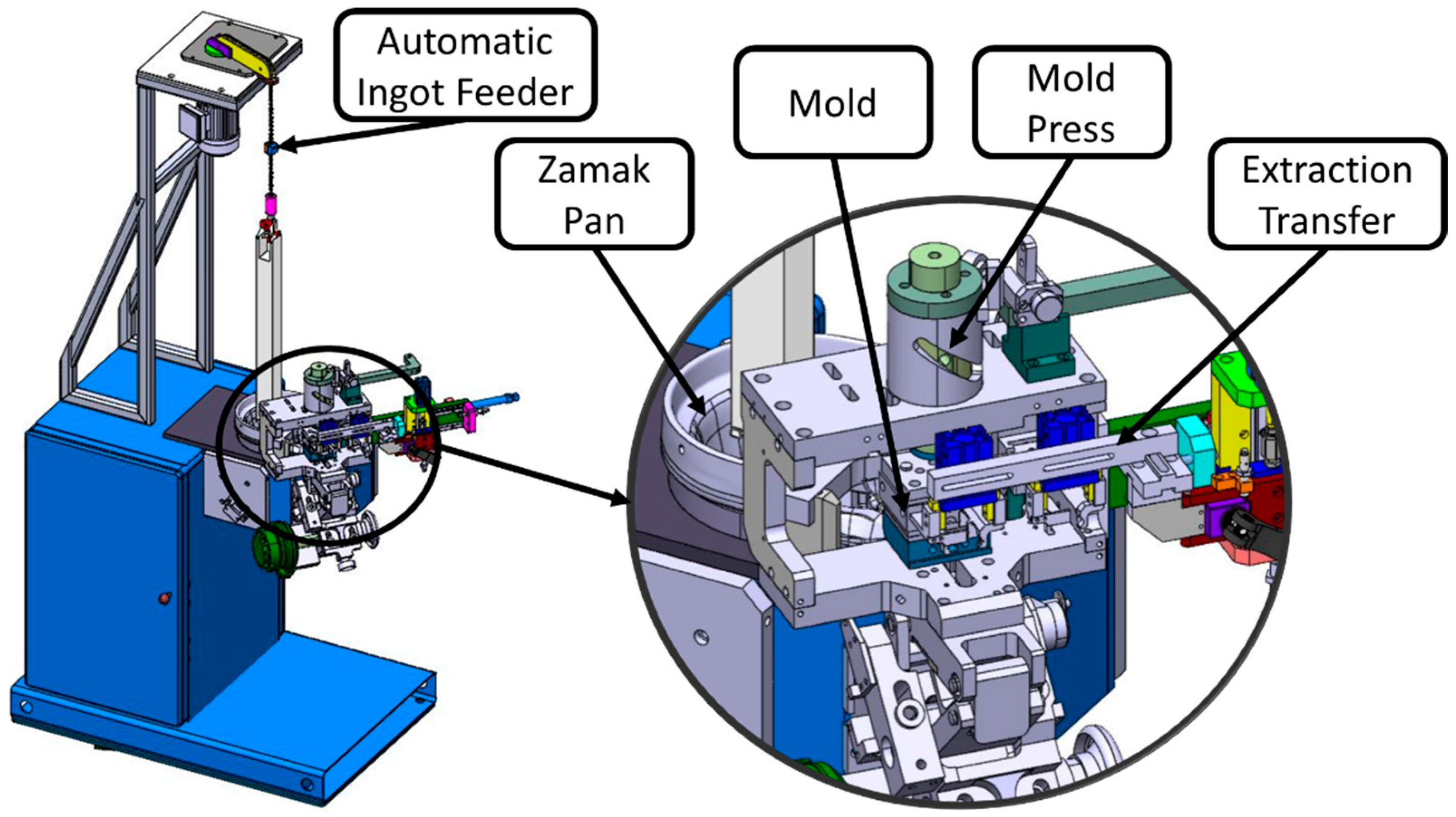
In terms of Zamak injection machines (
Figure 8), as previously mentioned, the intention is to maintain the company’s standard. Since the equipment can be easily upgraded to the current version, it can and should be reused in the new equipment concept implemented. In this way, it is possible to lower the initial investment costs without restricting the production rates of the new machines.
One of the problems found in the previous process is that there are several transport steps between different machines, which constitute basic tasks for the operators, such as counting and labeling boxes with a view to the need to carry out intermediate storage. These operations do not add any value to the product and, as Bowden cables are a product with low added value, they are even more impaired in terms of competitiveness with this type of operation.
In cutting equipment, the use of one fifth of an operator (20%) is considered, as the worker usually operates five cable-cutting machines simultaneously. The major problem with this type of equipment is the large variation in cutting length, of approximately ±3 mm. In addition to this, the length of the equipment also tends to be high.
After cutting the cable, there is an operator devoted to the first Zamak injection machine. In this process, in addition to the manual tasks, there is the possibility of grouped cables being damaged, due to being disorganized. The damage occurs when a terminal that is still hot after injection is placed in contact with the coating of another cable. There is also the possibility of oxidation appearing on the stripped cable next to the cable terminal, due to placement in the water tank, as shown earlier on the right side of
Figure 4.
In addition to the existing problems in the current processes, there are still a number of other points to be improved. Currently, most cutting equipment is automatic, essentially based on electric cutting systems, but this type of system cannot be used on coated cables due to the insulation effect of the polymers. Thus, electrical cutting cannot be used for this type of product using a coated wire rope, which constitutes a limitation.
In simple and repetitive tasks, work accidents can also occur due to operator fatigue. However, many of these operations can be carried out automatically, leaving only the detailed assembly tasks for the operator. In the particular case of Zamak injection machines, in addition to the repeatability of the task, there is also the possibility of projecting hot Zamak particles, where existing protections may not be sufficient to protect the operator. In this case, the cost of an operator for these simple tasks is approximately EUR 15,000 per year and per shift in Portugal; in cases of larger production volumes, where two or three shifts are necessary, this cost can easily reach EUR 45,000 per year.
In addition to this, the high level of competition between suppliers of components for the automotive industry has led to a loss in the number of projects achieved by some companies, with a greater loss of competitiveness having been identified in the cable cutting process and the first Zamak injection. This means that, to counteract this trend, investment in new, high-rate equipment is necessary, replacing equipment dedicated to only one operation.
Moreover, with regard to production capacity, it is increasingly common for companies to manage Bowden cable projects, which, in addition to the high production volumes required, rely on a set of references, where the components used are common, changing only the cutting lengths. In other words, there is a need to increase the capacity in operations involving cutting and stripping coated cables, without a loss of flexibility.
As a summary,
Table 2 describes the problems previously highlighted, pointing out some strategic solutions as well, corresponding to the first and second phases of the DSR methodology, respectively.
As can be seen by the identification of the problems, it is necessary to increase productivity, reduce labor and find low-cost solutions that are flexible enough to be adopted for a given family of products. Thus, the aim was to optimize the manufacturing process, creating a concept of flexible equipment for the Bowden cable subset, present in all Bowden cables, with higher production rates and greater safety for operators.
4. Results
The initial development phase (third phase of the DSR methodology) involved the schematic design of three concepts based on some equipment already known and others recently made available on the market. For brevity, the comparison criteria between the concepts and the main reasons that led to the choice of the final concept will be described below. These decision criteria were based on the previously described problems and were the following: flexibility, production rate, equipment size, cutting accuracy, ease of construction, cost and ease of access tools for maintenance purposes. The concept defined for development, defined in
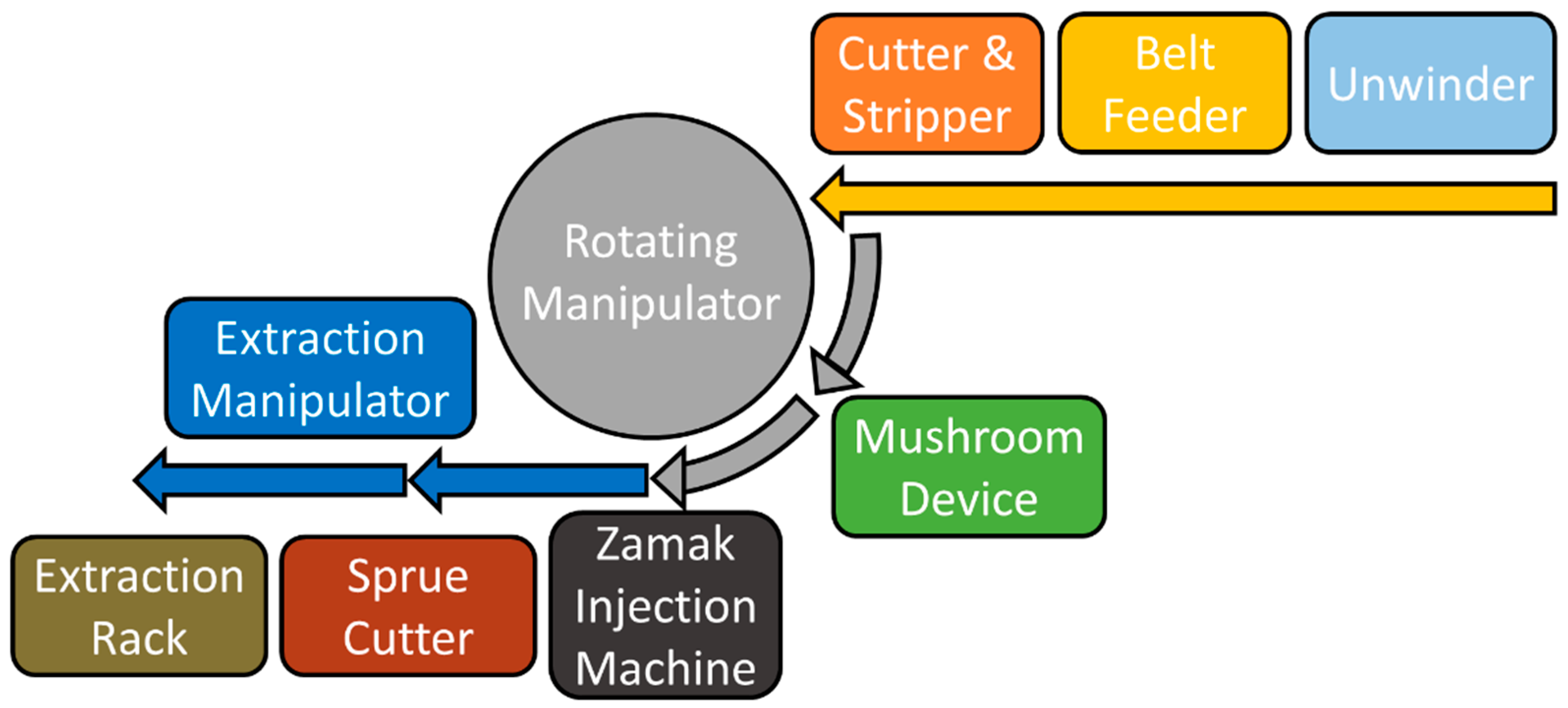
Figure 9, can be practically divided into two parts, separated by a rotary manipulator (in gray). In the first part, there is a bobbin unwinder with a compensator, which keeps the cable taut and allows the bobbin to unwind according to the need for the next set. This assembly is a belt drag that pulls the cable from the compensator and pushes it through the cable cutting and stripping devices. Once the cable is stripped, the rotary manipulator transports it to the mushroom making device and then to the Zamak injection machine. Once the mold is closed, the cable is grasped, and the rotary manipulator can be returned to the cutting and stripping device. After the Zamak injection has been carried out, a second manipulator transports the cables between the injection machine and the sprue-breaking device, and also between this and the extraction line.
In order to facilitate the interpretation of the diagram shown in
Figure 9, the following color scheme is used for the transport of the cable and corresponding device:
Yellow: belt hauling—conveyor pulls onto the cable from the unwinder and pushes through the stripper and cutter.
Gray: rotary manipulator—transports cable between cutting and stripping devices, mushroom making device and Zamak injection machine.
Blue: extraction manipulator—allows transport between the injection machine, sprung breaker and extraction hanger.
This concept stood out from the others initially considered due to being essentially the most compact and allowing for a better production rate, due to the feeding system that pushes the cable into the cutting and stripping device, instead of pulling the cable. This allows the cable to be fed at a high speed and over a fixed distance, regardless of the cable length. It is also quite flexible, as very short cables can be produced without a maximum length defined by the size of the machine. Another advantage of using this belt feeder with a servomotor is that, by adding an external encoder to the motor, it allows the real-time compensation of the cable length, improving the cutting precision. From the moment that the rotary manipulator starts transporting the cable, the cutting and stripping devices can be fed with the cable again and restart the cycle, which reduces the global cycle time. This manipulator, having three axes driven by a servomotor, in addition to eliminating the operator’s labor, allows the equipment to be flexible in parameterization, both in the introduction of new references and in small positioning adjustments. The same applies to the cutting and stripping dimensions, with the only disadvantage being that additional motorized axes are always more expensive. However, the cost is not significantly high, taking into account all the advantages that it presents. The complete extraction system, consisting of a sprue-breaker device, an extraction clothesline and an extraction handler, would be developed in the same way if any of the other concepts that were initially outlined in the brainstorming phase, but not considered for final development, were chosen.
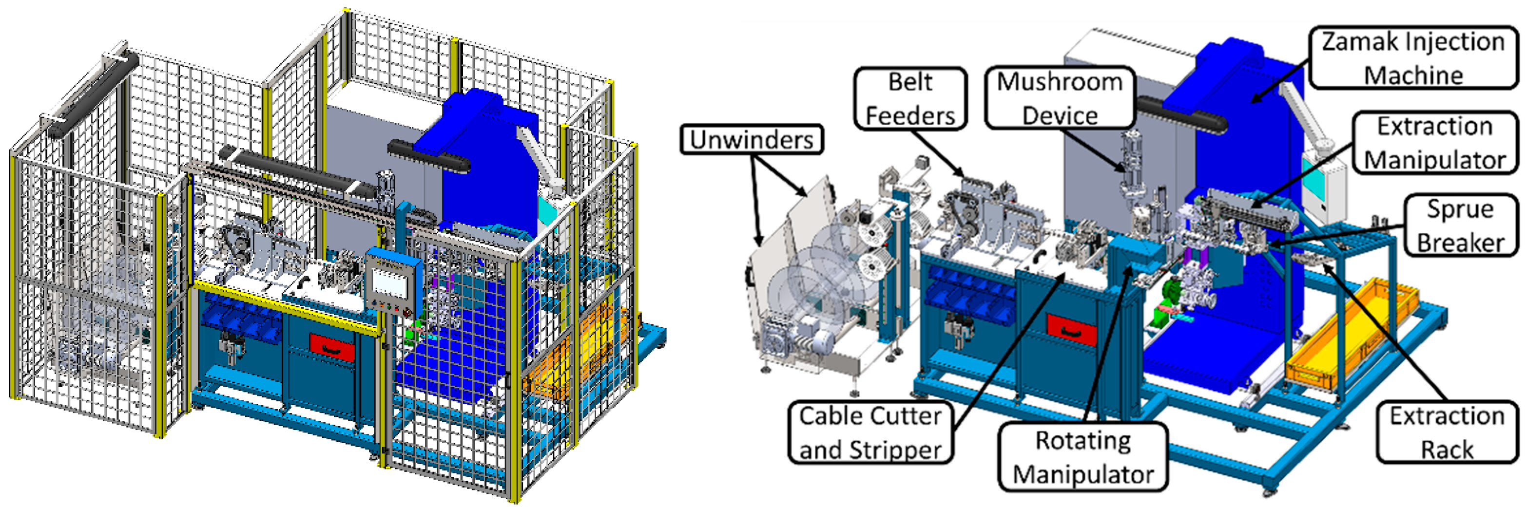
Thus, in
Figure 10, the final appearance of the new equipment is represented, with the view on the right side showing the protections removed for the better visualization of the respective devices that constitute it. This concept made it possible to develop symmetrical sets with the aim of producing two cables simultaneously, which makes it possible to double the production rate, since duplication does not create a bottleneck in any of the devices.
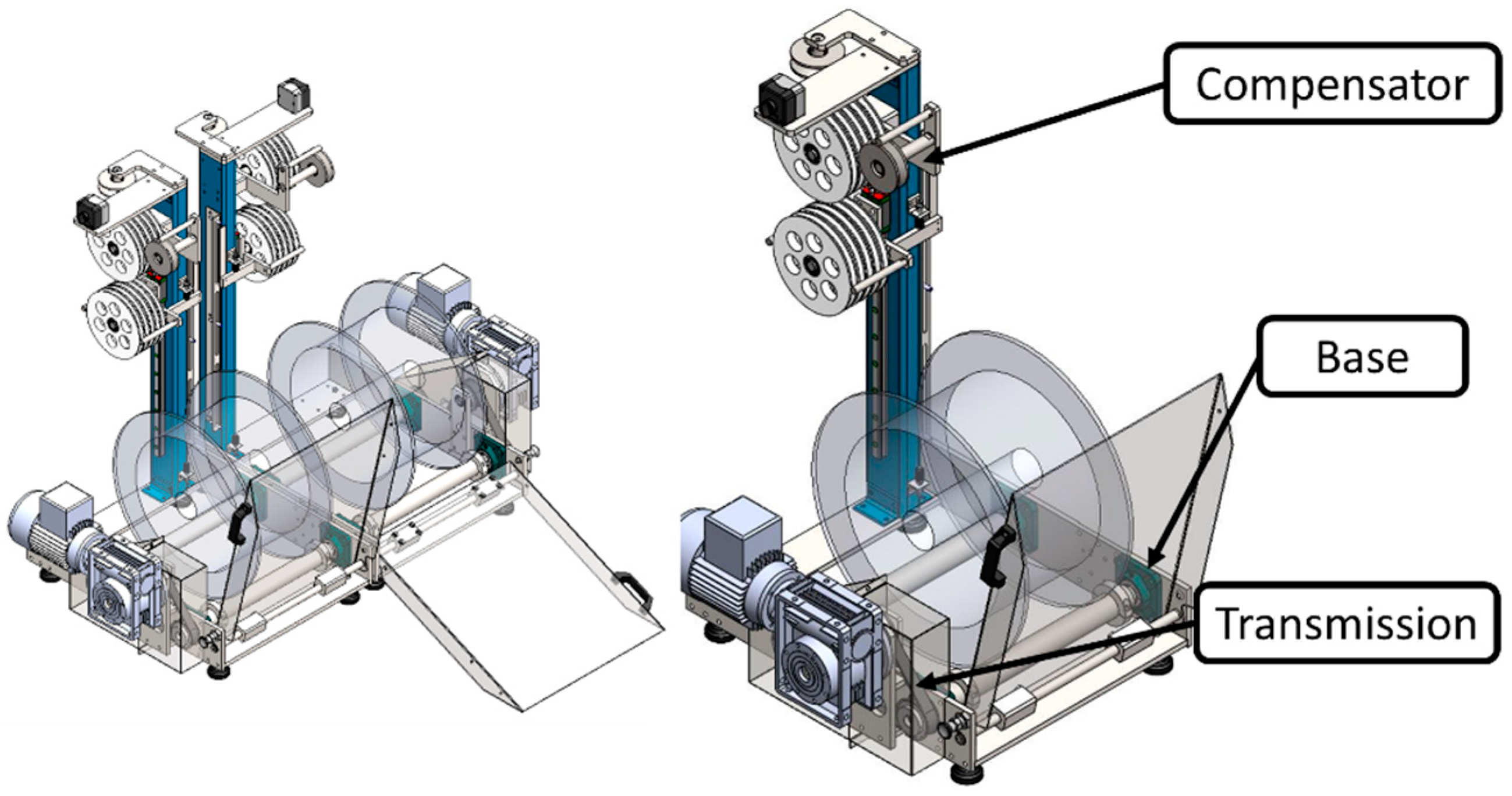
The first part of the equipment underwent the development of the coil unwinder. This unwinder could be considered for application in future projects in a standard way since it is easy to load using a ramp and is extremely versatile. Its versatility comes from the possibility of being assembled in the left or right position with the same pieces, since they are symmetrical, and also because it brings the possibility of the use of a pair of these devices in parallel, as shown in
Figure 11. This situation is convenient for the newly developed equipment because a pair of unwinders is beneficial to increase the productivity and can be used in an extremely compact way.
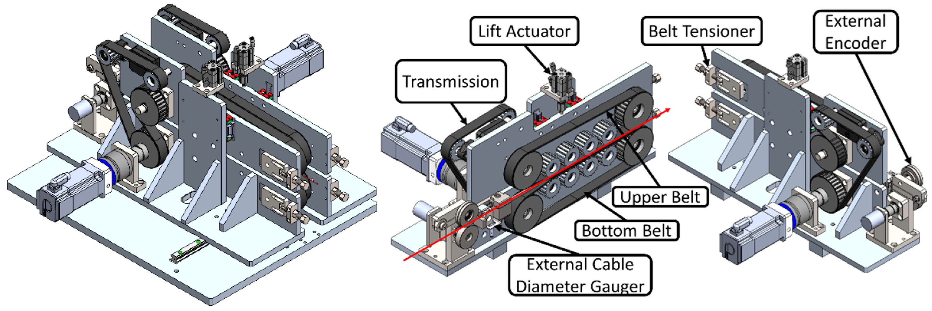
Controlling the unwinders are the belt drags shown in
Figure 12. This device was extremely difficult to develop, as it was necessary to respect the short distance between symmetrical sides. It is mainly responsible for the small dimensions of the equipment, so it was one of the parts that required the most attention in the design phase. The cable begins its journey by entering the encoder system, which was developed so that it does not slip, making the reading operation more accurate. At the output of the encoder, there is a gauge for the supply, in case the outer diameter of the casing is out of range. Then, there are the two belts that pull the cable from the unwinders and push it to the next device. These belts are driven by a transmission system with a double-toothed belt, pulleys and servomotors. The advantage of using belts is that, as they are made of rubber, they have good friction with the cable coating and reduce the possibility of slipping. Moreover, to prevent slipping, a pneumatic actuator capable of forcing the upper belt against the lower one was considered. This actuator, when withdrawn and the tensioner released, allows the changing of the belts. The useful life of these belts is also extended, since the cable walks off-center on the contact faces and they can be rotated in order to wear the opposite side. The pair of drags has a fixed side, while the other has movement to move away from the symmetrical set and thus allow access to the interior.
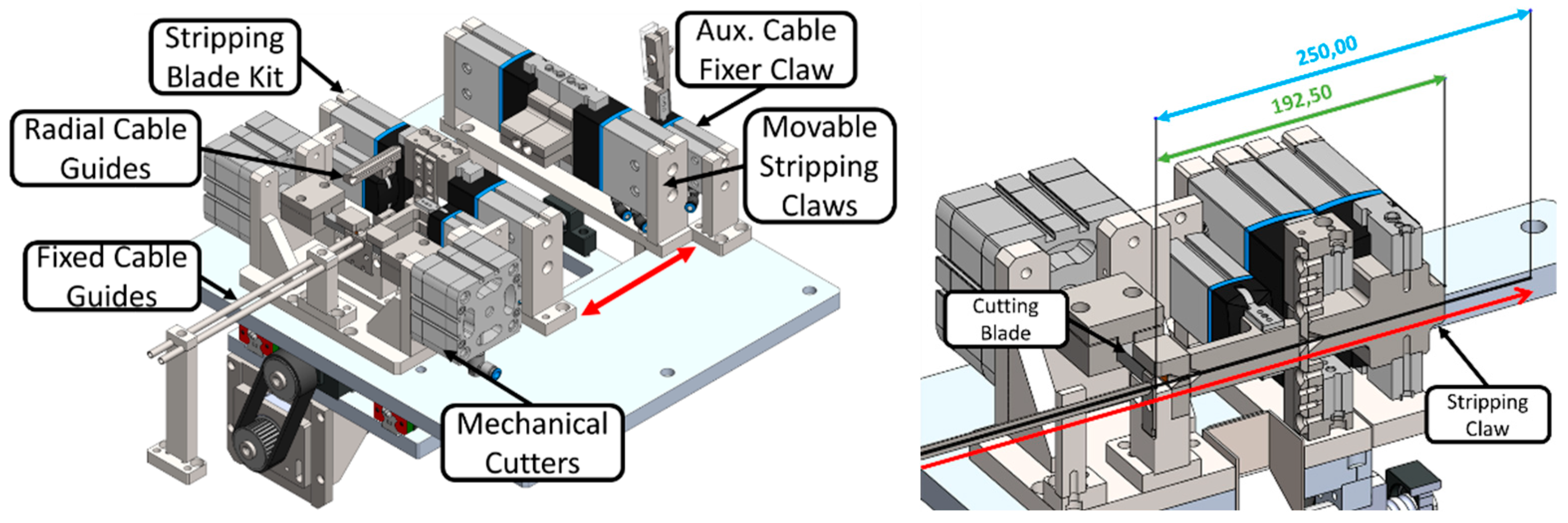
Belt drags introduce the cables into the cutting and stripping device. This device, depicted in
Figure 13, was the most challenging to develop, as the cables pass through it in a pushed fashion. This led to the need to guide the entire length of the cable from the moment that it leaves the drag to the fixed cable guides, through the cutting blades, the radial opening guides, the stripping blades and, finally, the movable stripping grapples. Another difficulty with this set was the need to make it as compact as possible, since the minimum distance between the cutting blades and the end of the stripping jaws determines the minimum cable cutting length. It is, together with the belt drag system, the most innovative system in the equipment, as the minimum cable length is less than 192.5 mm, without restricting the maximum cutting length. As it is quite compact, it was also one of the greatest contributions to the small dimensions of the equipment.
The operation of this device is quite complex since it is possible to determine different lengths of stripping due to the movement of the stripping claws. These are able to convey the cables very quickly between the stripping blades to the fixed auxiliary gripper, which temporarily fixes the cables for the repositioning of the stripping jaws. The stripping jaws always start the cycle with the stripping blades. These blades will only close and cut the coating as soon as the stripping jaws reach the defined dimension. Then, the stripping claws continue their movement towards the auxiliary claw, where the coating tip is torn off the cable.
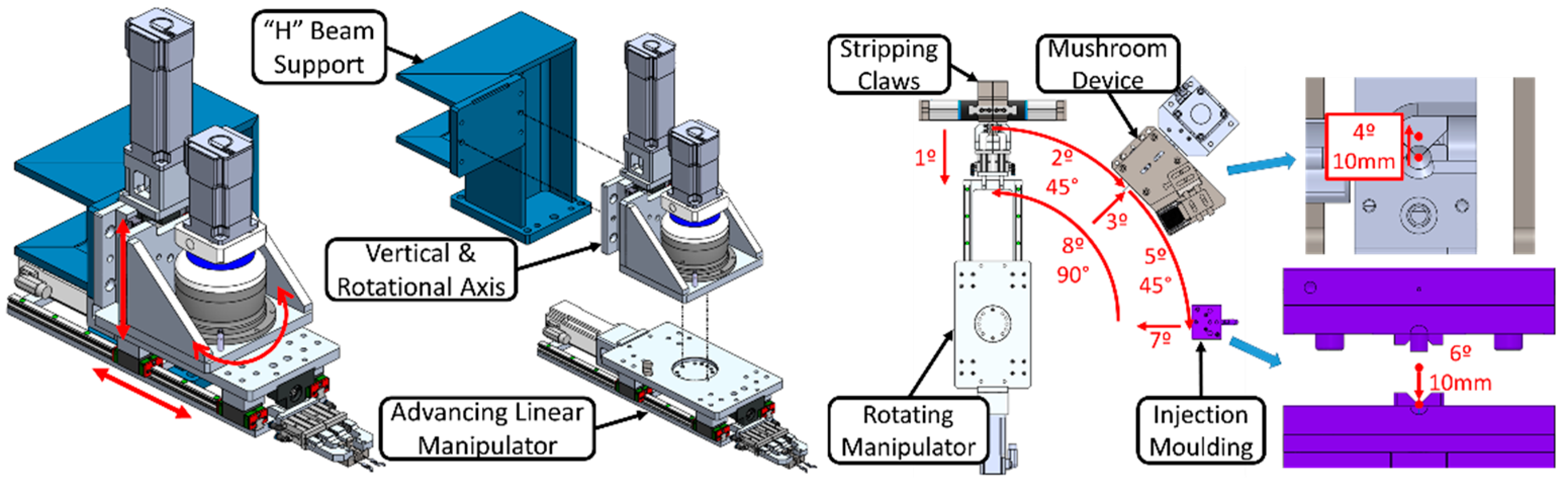
From the moment that the cables are cut and stripped, the rotary manipulator shown in
Figure 14 needs to start its cycle, removing them from the cutting and stripping device. This will carry the cables to the device to create the mushroom and, finally, to the mold of the injection machine. From the moment that the mold closes, the cables are stand-fixed, and the manipulator can return to its initial position to pick up two new cables. This manipulator consists of three axes with movement driven by a servomotor. The main axis is that of rotation, since it is this movement that makes it possible to place the device for the creation of the mushroom and the injection machine at 45 and 90 degrees in relation to the output of the cables from the cutting and stripping device, and also within a radius that is extremely reduced, which makes the equipment more compact. This radius was determined by the dimensions of the devices, allowing for no collisions between them and during the transport of the cables. It was also necessary to use a height adjustment axis, which allows the manipulator to pick up the cables from above, to be able to extract them from the set to create the mushroom and even to take the cables into the injection mold. The feed axis is necessary for two reasons: (a) the manipulator needs to accompany the movement of the stripping claws to collect the cables, and (b) to introduce them frontally in the device to create the mushroom. The other advantages of this manipulator, as it is built with three electric axes, are its speed and positioning accuracy. Initially, the use of an industrial robot was considered, but, due to the large volume occupied, this possibility was neglected. Next, collaborative robots were considered, as they have smaller dimensions, but in this case there are speed limits for safety reasons and therefore it was decided to build a specific manipulator. It was also possible to build this manipulator at a lower cost than the collaborative robot, without losing the flexibility required for the machine.
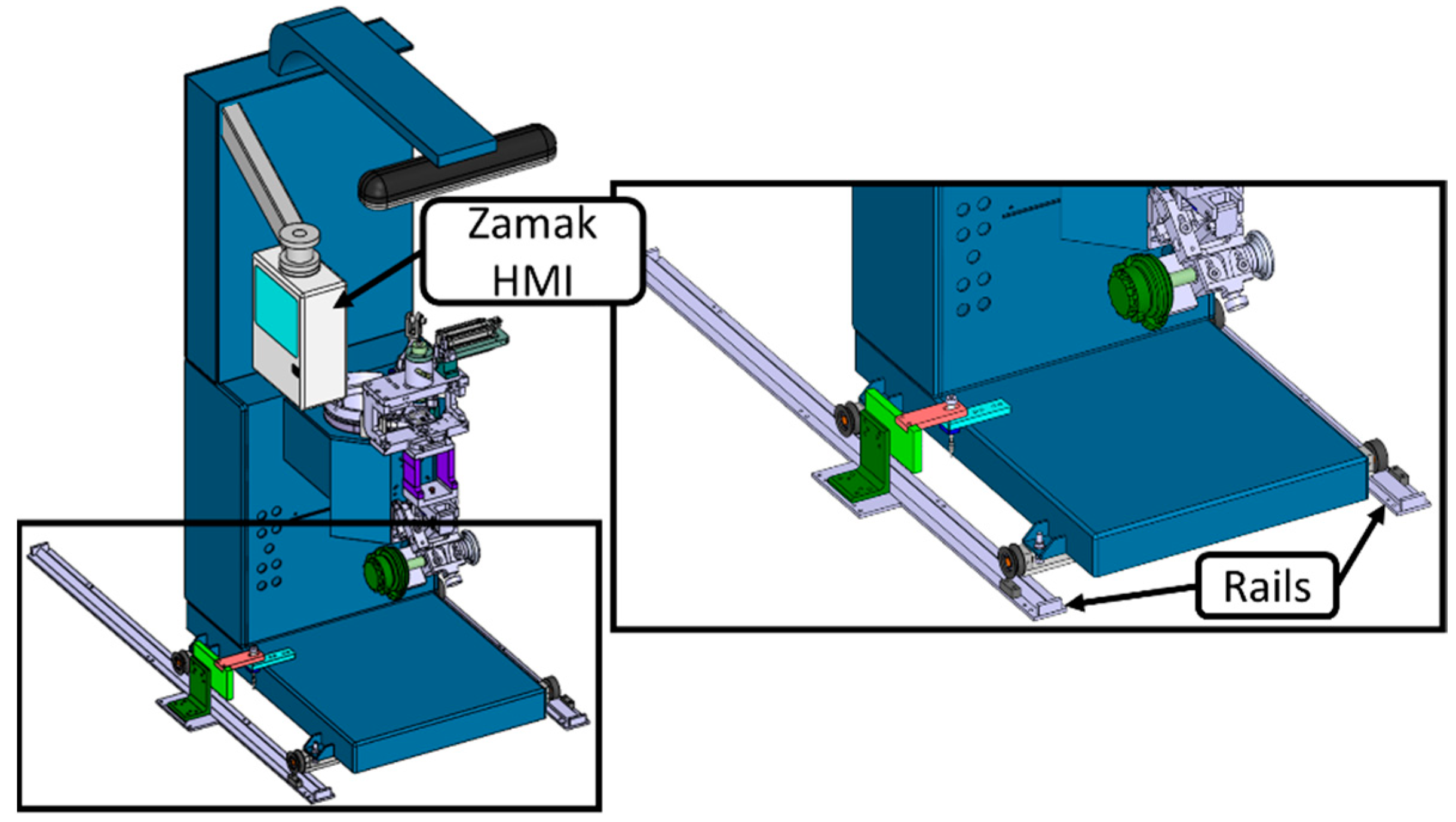
At the injection machine level, the main idea is to use the equipment typically used (
Figure 15). The main reason was the cost, as the latest versions of these machines cost more than EUR 20,000, and it is possible to restore and upgrade existing machines for a small fraction of this price, thus contributing to the reuse of equipment, avoiding their landfilling and the respective environmental consequences [
36,
65]. This sub-equipment was placed on rails, in order to facilitate access to its components for maintenance purposes. A dedicated HMI is also applied, only used by technicians to check and adjust the Zamak injection parameters in the equipment during interventions.
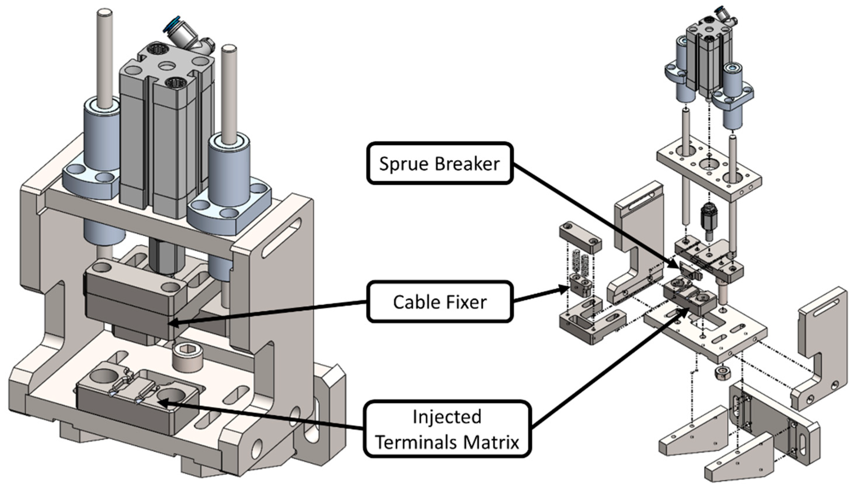
After the injection, it is possible to identify the extraction devices. The first of these is the device for the breakage of the sprue, shown in
Figure 16. It is a simple device in which only a pneumatic actuator is used with downward movement, which first fixes the cables in the mold of the Zamak terminal and then breaks the sprue from the terminals. This device allows the exit of the sprues through the inferior part of the device, and these sprues are later reused for recycling (re-melting).
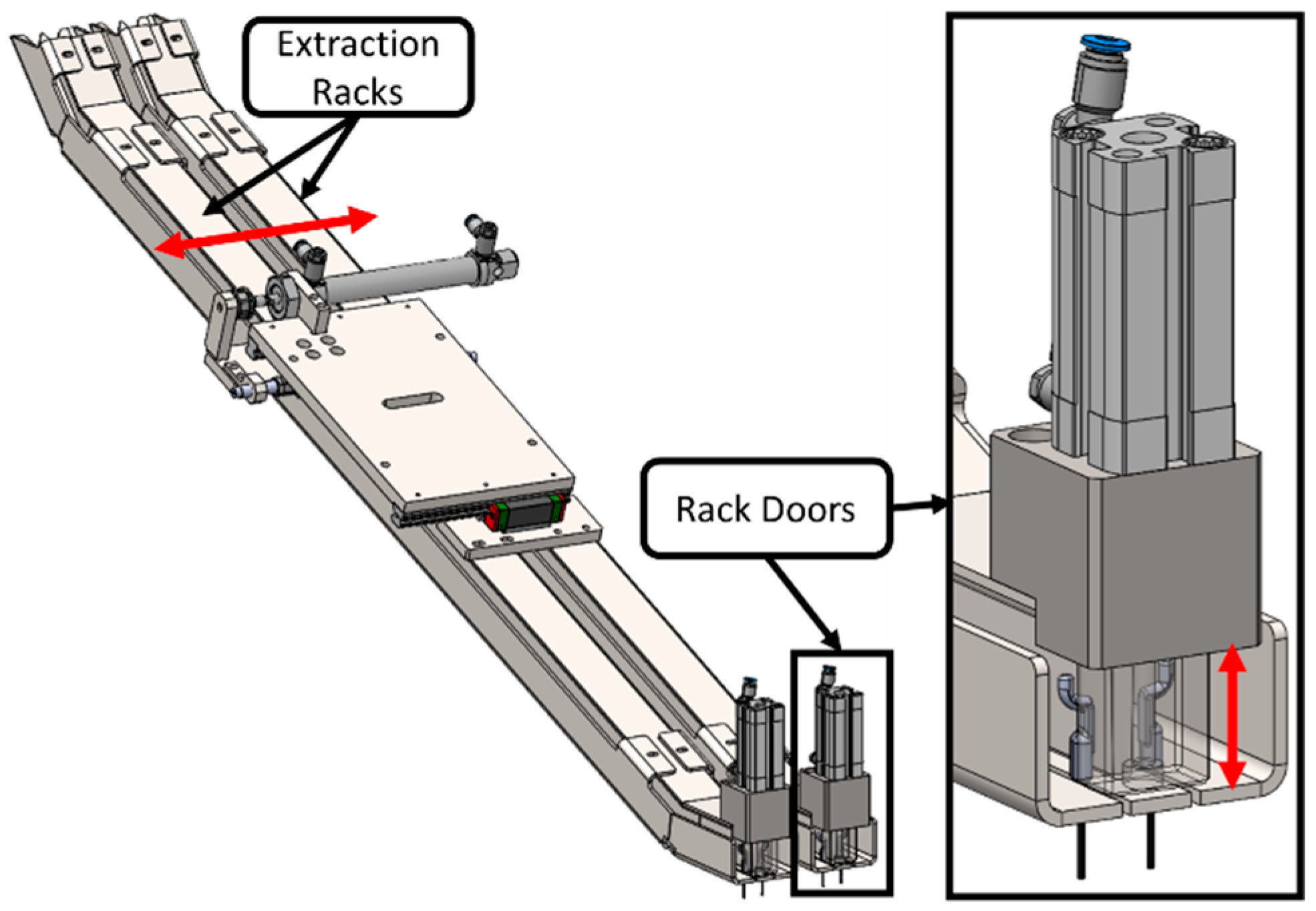
The final device of the equipment is the cable cooling hanger, represented in
Figure 17. This system aims to reduce the risk of damage to the cable coating with the Zamak terminal recently injected. This system allows the extraction to be organized and ensures that the hot terminals (with the Zamak still cooling down) do not touch the polymeric coatings of the other cables. It is composed of two holders that move laterally, with the aim of the equipment automatically changing the holder as soon as the other one is full. Each holder also has a door, which only allows the operator to remove the cables to the box as soon as they are cooled down, without stopping the equipment.
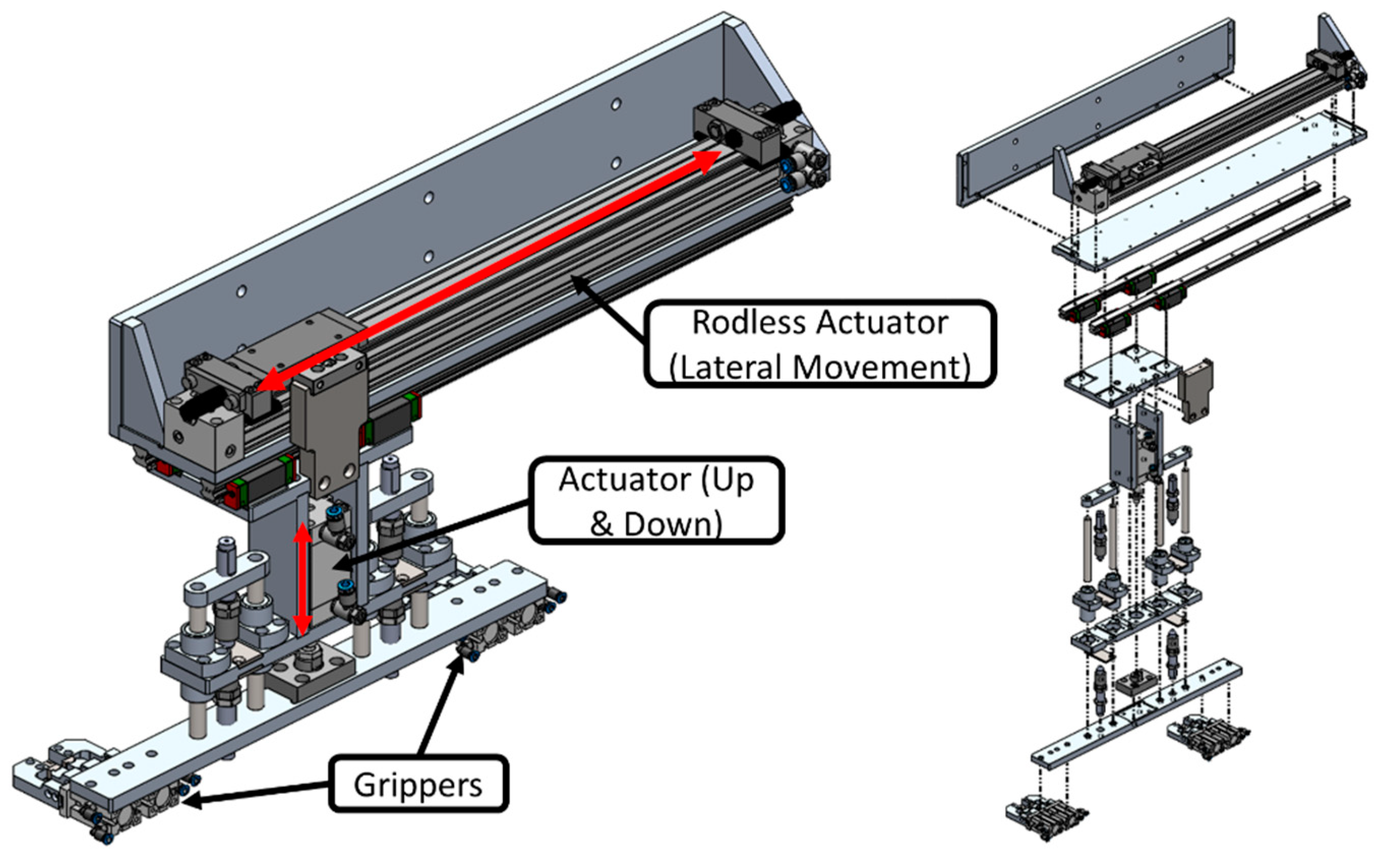
Finally, the details of the last set, which relates to the extraction of the cables from the Zamak injection machine, are described. This is the manipulator shown in
Figure 18, which transports the cables between the Zamak injection machine and the sprue-breaking device, and between the latter and the extraction line. For lateral movement between the devices, a rodless pneumatic actuator was used. In this way, the width of the manipulator was kept more compact, creating a step of 380 mm between the devices. It also includes the upward and downward movement of the grippers, as they collect and place the cables approaching from the upper part.
After the development steps, which corresponded to the third phase of the DSR methodology, and after all the verifications carried out, the implementation, the fourth phase of the methodology, was carried out. With the development of this concept, it was possible to reach a production rate higher than 1440 p/h. The servomotors were dimensioned for 720 p/h since the double machine was developed to produce two cables simultaneously. Thus, it was possible to directly duplicate its production. In the testing and tuning phase, this value was even slightly surpassed, with a reliable and consistent cadence of 1500 p/h being achieved.
In addition to the high cadence, the major difference between processes is attributed to the workforce. The need for an operator dedicated to the manual injection machine and the cutting equipment can be eliminated in relation to the previous process conditions, which represents a huge reduction in operating costs and has a great influence on the price and competitiveness of the part. In the new process, the intention is to use one operator for every two machines.
It should also be noted that all the equipment developed occupies less than 12 m² of the shopfloor, and the safety of the operator is improved because they are located away from the areas of greatest danger (Zamak injection machine).
In
Table 3, a summary of the most important data referring to the old process and the new process can be found, verifying that the cost of the equipment is essentially the same, but the savings in terms of operation are significant, which causes an extraordinary decrease in the cost per part, making the product much more competitive.
The costs mentioned above include the control system, consisting of a Schneider Electric programmable linear controller (PLC). The programming of this PLC was carried out by automation technicians from the company where the prototype was installed, following previously defined instructions and taking into account the capacity of each actuator and sensor connected to the PLC.
Given the cost of the equipment and the operational advantages achieved through its use, it was necessary to verify whether the replacement of the old equipment should be considered, taking into account the necessary investment. Taking into account the data in
Table 3, it was possible to verify that the gains achieved with the new equipment would allow a return on investment in approximately 9.8 months, which is a very acceptable period given the duration of this type of project and the flexibility that the equipment presents to be adapted to future projects. In
Supplementary Material Video S1, a video is presented that shows the prototype in operation and the different innovative concepts developed around this challenge.
5. Discussion
Starting from a concept that was shown to be uncompetitive, this work describes the steps taken and the new concepts developed to make a manufacturing process more expeditious and competitive. Some existing solutions in the initial equipment were carried over to the new concept, in the absence of ideas that were manifestly disruptive and capable of producing truly attractive effects. All devices that directly interfered with the productivity of the equipment and that were not able to satisfy the new requirements were replaced or improved. As in works previously presented by other authors [
34,
42,
43,
44,
46,
47,
65,
66,
67], the choice to solve the problems identified essentially involved the adoption of conventional automation driven by programmable devices, to the detriment of robotics, despite initially considering the use of robotics. In fact, for situations such as the case under study, where competitiveness and a quick return on investment are crucial factors for the adoption of the developed concepts, conventional automation usually represents a more economical solution that consumes less area on the shopfloor. In addition, as these are more common devices, their maintenance becomes easier and more economical, and there are usually components that are common to other equipment, as well as knowledge that is already possessed by a greater number of maintenance staff. Moreover, the use of conventional automation also provides the opportunity to recover materials previously used in other projects and equipment, which has been put out of service but is still able to function perfectly according to the requirements now outlined, preventing this material from being discarded and landfilled. This has already been recommended by other authors, with a view to reducing the environmental impacts of industrial activity [
36,
66].
Once the decision on the technological basis to adopt had been made, it was important to develop new concepts that were efficient in functional terms, allowed the desired production rates, were robust and reliable enough to support the daily production of three shifts and allowed us to significantly reduce the operating costs added to the equipment. The reduction of the occupied area was also a critical factor in the project, given that the space is usually rented, and this represents non-negligible operating costs.
The main innovations in this concept are the cable feeding system (wire rope) and the rotation system that allows other operations to be carried out at the end of the cable in an area very close to the cable feeding system. The cable feeding system increases the flexibility of the system, no longer imposing a minimum and maximum cable length required to operate the equipment, while the rotation system drastically reduces the need for space for the equipment, placing the devices necessary for operation after the cutting and holding of the mushroom within walking distance of the cable feed. These concepts are as disruptive as those presented by Araújo et al. [
46], Nunes et al. [
47] and Costa et al. [
66], who, starting from uncompetitive solutions, managed to develop revolutionary mechanical/automatic systems capable of changing the paradigms on which certain previously institutionalized manufacturing processes were based.
The reduction in space occupation is also a factor to be taken into account, mainly considering that the space now needed is almost 50% smaller than what was previously needed. Aiming for a significant increase in production, the ‘occupied area’ factor also contributes significantly to the set of savings that companies should consider, since the costs of occupied space represent an important factor in companies’ fixed costs.
The developed concepts allowed for a very attractive final cost for the equipment, which was proven by the realization of the prototype (development costs were not included, since this was allocated to an academic work that served as the basis for this article). The return on investment (ROI) of approximately 10 months obtained for this project is quite similar to another process automation concept presented by Costa et al. [
67], whose ROI was established as 12 months. Santos et al. [
68], also working in the automation of a manufacturing process related to the garment industry, achieved a value of around 14.5 months, showing that some more complex solutions that do not eliminate as many jobs can present slightly higher ROIs. When automation solutions use robotics, the higher cost of these systems has direct implications for the ROI, as demonstrated in the work presented by Silva et al. [
12], where the ROI was calculated as 21.5 months. This was also evident in another work presented by Silva et al. [
13], based only on conventional automation, in which the ROI was estimated to be only 5 months. These were some of the reasons behind the adoption of conventional automation, to the detriment of solutions involving robotics.
As the main outcomes and transferable knowledge, and complying with the fifth and final phase of the DSR methodology, the following achievements should be considered.
- (a)
The innovative concept of wire feeding and its fixation through claws for cutting and the creation of the mushroom offers a solution that can be applied in other manufacturing processes, with identified advantages in terms of the precision of the final product. This solution also proves to be extremely compact.
- (b)
The rotating system used in this work makes the equipment more compact, accommodates the different devices involved in the process more closely and does not present any inconvenience in terms of semi-product transport, not interfering negatively with the required quality level. It is a relatively inexpensive device, easy to program and practical, that can be advantageously used in other manufacturing processes.
- (c)
If the systems are developed from the outset with environmental and space concerns in mind, components that were previously used and put out of service can be used, with undeniable advantages for the environment and a reduction in the space occupied, allowing for the use of more compact solutions without affecting access when required for cleaning and maintenance operations.
6. Conclusions
The main objective of this work was to develop equipment endowed with high productivity and flexibility, capable of producing the first subset of Bowden cables provided with the first injected terminal, increasing the production capacity to improve the competitiveness in the production of this type of product for the automobile industry.
Another objective of the new equipment was to reach a production rate of 1100 parts/h, which is the maximum that double-uncoated cable machines are normally capable of producing. The prototype of the equipment was developed to produce 1440 p/h, having even stably produced 1500 p/h, surpassing the expectations of reaching a higher cadence than the most modern machines on the market.
However, compared with more modern uncoated cable cutting machines, these need a usable area of 22 m2. Thanks to the new feeding, cutting and stripping concept, a total area of 11.58 m2 was achieved. Regarding flexibility, the developed equipment also exceeds the requirements, as it is prepared for cables and coatings of different diameters. The operator’s safety is improved since the workers are located away from the danger zones (mainly the Zamak injection machine). Photoelectric barriers are also used along with an air cut and door opening command, allowing the operator to intervene in the equipment’s operation safely.
The manufacturing cost of the prototype already built and subjected to the testing phase is EUR 56,000, a value that is very acceptable, taking into account that the existing offers on the market are substantially more expensive (~ EUR 100,000). Finally, evaluating the cost of the equipment and its influence on the operating cost, as shown in
Table 3, it is possible to verify that a return on investment for the new equipment can be obtained in less than 10 months.
Taking into account the result obtained, the high flexibility achieved, the high production rate and the reduction in the area occupied on the shopfloor through its compact dimensions, combined with a cost that is almost 50% lower than that currently exhibited in the market, this new concept of equipment was immediately adopted by the company, which undertook the challenge of developing this new concept, immediately transforming it into a new standard for the manufacturing of the product in question.

 ,
, 


