Review

Fluid Film Bearings and CFD Modeling: A Review

by
Demetrio Pérez-Vigueras
,
Jorge Colín-Ocampo
*,
Andrés Blanco-Ortega
,
Rafael Campos-Amezcua
,
Cuauhtémoc Mazón-Valadez
,
Víctor I. Rodríguez-Reyes
and
Saulo Jesús Landa-Damas
Departamento de Ingeniería Mecánica, Tecnológico Nacional de México/CENIDET, Cuernavaca 62490, Morelos, Mexico
*
Author to whom correspondence should be addressed.
Machines 2023, 11(11), 1030; https://doi.org/10.3390/machines11111030
Submission received: 6 October 2023 / Revised: 27 October 2023 / Accepted: 1 November 2023 / Published: 17 November 2023
(This article belongs to the Special Issue Rotor Dynamics and Rotating Machinery)

Abstract

:
This paper is a review of the literature about CFD modeling and analysis of journal, thrust, and aerostatic bearings; the advantages and disadvantages of each are specified, and the bearing problems that have been analyzed are discussed to improve their designs and performance. A CFD transient analysis of journal bearings was conducted using the dynamic mesh method together with movement algorithms while keeping a structured mesh of a good quality in the ANSYS Fluent software to determine the equilibrium position of the journal and calculate the dynamic coefficients. Finally, areas of opportunity for analyzing and designing fluid film bearings to improve their performance are proposed.

1. Introduction

Fluid film bearings are important components in the operation of rotating elements in rotor-bearing systems, such as machine tools, drillers, gas turbines, generators, and engines, as well as in any device that has a rotating element that is exposed to vibration. The classification of fluid film bearings (or only bearings) is given according to their principle of operation, the direction of the load, the type of lubricant, and their geometry and/or construction [1]. Depending on how lubricant film pressure is generated to support the rotor load, bearings are classified as hydrodynamic or hydrostatic bearings. In hydrodynamic bearings, the lubricant film pressure is generated by the journal’s rotational velocity inside the bearing, and in hydrostatic bearings, the pressure is supplied by an outside source. If the load acts in a direction perpendicular to the rotation of the shaft, this is called a journal bearing, but if the load acts in a direction parallel to the rotating shaft, this is called a thrust bearing. According to the type of lubricant, bearings are classified as oil, gas, water, and magnetorheological fluid bearings. Depending on their geometry and construction, there are plane (circular) bearings, grooved bearings, texturized bearings, bearings with pockets, bearings with tilting pads, floating bushing bearings, circular arc (lobe) bearings, and combinations thereof. Each type of fluid film bearing has advantages and disadvantages over the others; therefore, the selection of the type of bearing is made according to the operating conditions of the rotor–bearing system.
This document focuses on providing a review of the literature on the CFD modeling and analysis of journal, thrust, and aerostatic bearings, specifying the advantages and disadvantages of each, and discussing the bearing problems that have been analyzed to improve their performance. Journal bearings that were plain, grooved, texturized, had pockets, had tilting pads, had floating bushing, and were lubricated with FMR were investigated. On the other hand, the effect of misalignment on the static and dynamic parameters of journal bearings was studied. A CFD transient analysis of journal bearings was conducted using the dynamic mesh method together with movement algorithms while keeping a structured mesh of a good quality in the ANSYS Fluent software to determine the equilibrium position of the journal and calculate the dynamic coefficients of the bearings through the linearization of hydrodynamic forces.

2. Fluid Film Bearings

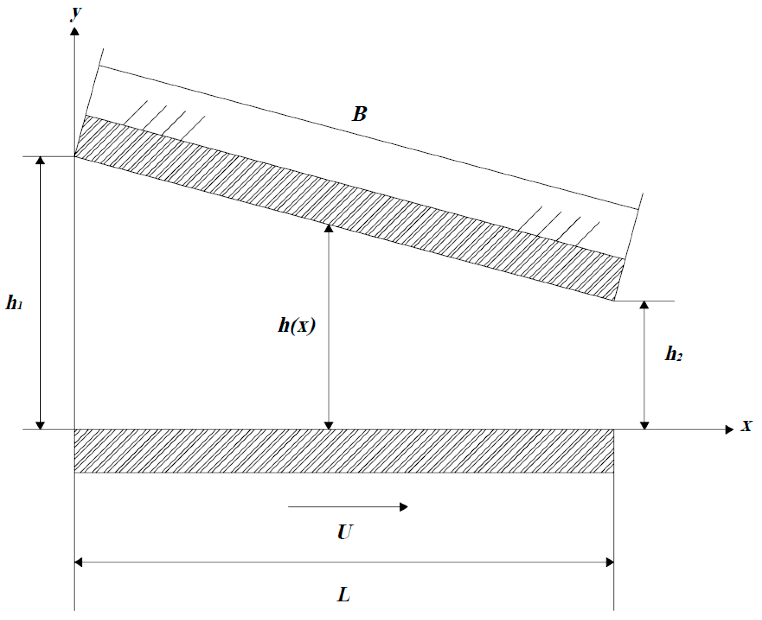
2.1. Theory of Fluid Film Bearings

The simplest form of a journal bearing consists of two rigid cylinders. The outer cylinder (bearing) is usually stationary, while the inner cylinder (journal) is made to rotate at an angular velocity ω ( r a d / s ). Between both bodies, there is a gap named the radial clearance C = R b R j , where R b and R j are the bearing and journal radii (m). The weight W (N) and the angular velocity ω of the rotor cause the journal center O j to be displaced a distance e (eccentricity (m)) and angle ϕ (attitude angle) from the bearing center O b . This is known as the static equilibrium position (Figure 1). The equilibrium position then modifies the clearance, which is measured in the radial direction and is known as the lubricant film thickness h (m). This is given by
h = h θ = C + e c o s θ h ¯ = 1 + ε   c o s   θ
where θ is the angular coordinate, and ε = e / C and h ¯ are the dimensionless ratio of eccentricity and fluid film thickness.
To determine the pressure of journal bearings, the Reynolds equation is solved analytically or numerically, which results from applying the Reynolds assumptions (given in [1]) to the Navier–Stokes equations. The Reynolds dimensionless pressure equation for a journal bearing is given by
𝜕 𝜕 θ ~ h ¯ 3 𝜕 p ¯ 𝜕 θ ~ + D L 2 𝜕 𝜕 z ¯ h ¯ 3 𝜕 p ¯ 𝜕 z ¯ = 12 π 𝜕 h ¯ 𝜕 θ ~ + 24 π ω 𝜕 h ¯ 𝜕 t
p ¯ = p / μ N R C 2 , θ ~ , and z ¯ = z L / 2 are the dimensionless pressure, dimensionless angular coordinate, and axial coordinate. D and R are, respectively, the diameter and journal radius (m), L is the length of the bearing (m), μ is the fluid viscosity ( P a · s ), N is the journal operation velocity ( r p s ), and t is the time (s).
Generally, for simplicity, the analytical solutions of the Reynolds equation for calculating the film pressure are, according to the journal bearing theories, infinitely long (3) and infinitely short (4) [1,2]; in the steady state, they tend to 𝜕 h ¯ 𝜕 t = 0 .
𝜕 𝜕 θ ~ h ¯ 3 𝜕 p ¯ 𝜕 θ = 12 π 𝜕 h ¯ 𝜕 θ ,   𝜕 p ¯ 𝜕 z ¯ = 0   to   L / D > 2
D L 2 𝜕 𝜕 z ¯ h ¯ 3 𝜕 p ¯ 𝜕 z ¯ = 12 π 𝜕 h ¯ 𝜕 θ ,   𝜕 p ¯ 𝜕 θ   to   L / D < 0.25
A load acting along the axis of the shaft is called a thrust; then, a bearing that supports the thrust is called a thrust bearing [1]; it has an inclined pad that generates a variable fluid film thickness h (Figure 2):
h x = h 1 x B h 1 h 2  
where h 1 and h 2 are the film thicknesses at the inlet and outlet of the pad, respectively, and B is the width of the pad in the direction of the plane of motion. If nondimensional quantities
m = h 1 h 2 ,   x ¯ = x B ,   h ¯ = h h 2
are introduced, Equation (12) can be written as follows:
h ¯ x ¯ = m x ¯ m 1
The Reynolds equation for the pad can be written as follows, and the pad is assumed to be infinitely long in the direction normal to the page:
d d x h 3 d p d x = 6 μ U d h d x  
Aerostatic bearings are thus characterized because the lubricant fluid film is generated from the external pressurization of a compressible fluid—mainly air (Figure 3). Aerostatic bearings have more and more applications in ultra-precision machine tools due to their specific advantages, such as their low driving power and friction, high movement accuracy, thermal stability, and others [3].
According to von Osmanski [4], after defining the circumferential and axial coordinates θ and z ~ , the isothermal, compressible, and transient modified Reynolds equation (MRE) for an ideal gas can be written as
𝜕 𝜕 θ p ~ h ~ 3 𝜕 p ~ 𝜕 θ + 𝜕 𝜕 z ~ p ~ h ~ 3 𝜕 p ~ 𝜕 z ~ = S τ Ω ~ 𝜕 𝜕 θ p ~ h ~ + 2 S τ 𝜕 𝜕 τ p ~ h ~ + q ~ i n j
where
q ~ i n j = 12 R 2 μ R S T i s o p a 2 C 3 q i n j   and   S τ = 6 R 2 μ ω τ C 2 p a
Figure 3. Illustration of an air journal bearing; the pressure holes are distributed equidistantly in the angular coordinates. Geometry of the pressurization orifice–recess (the image is adapted from [5]).
Machines 11 01030 g003

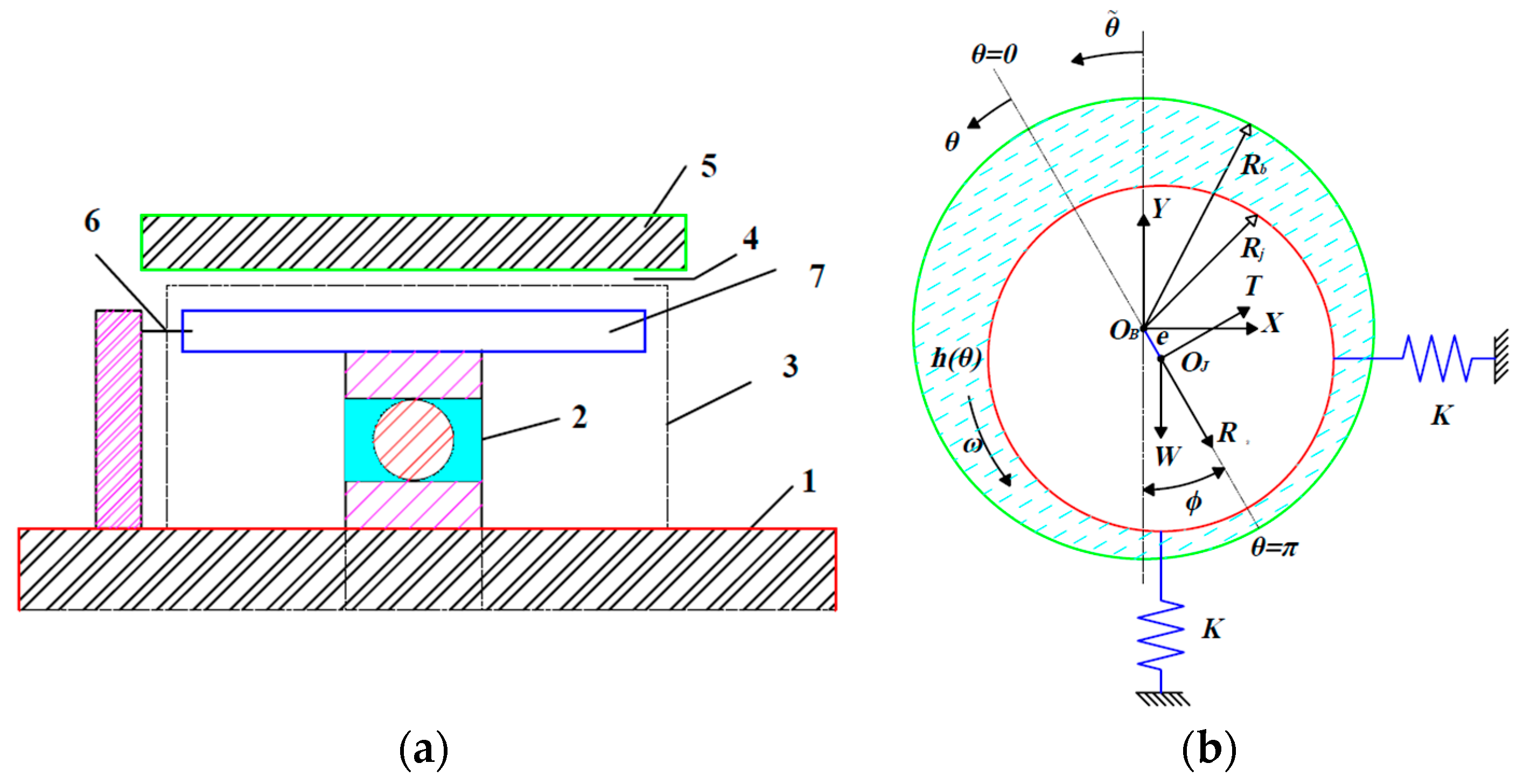
2.2. Journal Bearings

The infinitely long and infinitely short bearing theories are used in the analysis and design of bearings by applying the Sommerfeld condition, which returns all negative pressure to zero. With the infinitely short bearing theory (4), Naïmi [6] modeled two resulting sections of a journal bearing with a circumferential groove, and Weißbacher [7] designed and built a two-lobe-bore bearing profile with two lubricant supply ports in the load direction; here, the bearing profile was determined with an optimization algorithm. For a short bearing, Miraskari [8] considered third-order terms, analytically obtained the non-dimensional linear and nonlinear bearing dynamic coefficients, analyzed the stability of flexible rotors, and found that there were two bifurcation regions: the super and subcritical. The analytic solution of a finite-length bearing is more complex to calculate; some researchers used a variable separation method in an additive and multiplicative way to determine the pressure field and the hydrodynamic forces [9,10,11].
Using numerical methods, such as the finite difference method (FDM) [12,13,14,15,16,17] and the finite element method (FEM) [18,19,20], the Reynolds equation is solved; later, the static and dynamic characteristics of the journal bearings are determined to carry out a stability analysis. Usually, in the steady state, from a given eccentricity ratio ε , the attitude angle ϕ is iteratively determined until the equilibrium condition of Equation (11) is achieved.
F y F x 0 = F 0 = W 0
The dimensionless force components at the reference frame X-Y are given by
F ¯ X = F x μ N L D R / C 2 = 1 4 0 1 0 θ p ¯ sin θ ~   d θ ~ d z ¯ F ¯ Y = F Y μ N L D R / C 2 = 1 4 0 1 0 θ p ¯ cos θ ~   d θ ~ d z ¯
where θ ~ = θ + ϕ is the dimensionless angular coordinate. The attitude angle, dimensionless load capacity, and Sommerfeld number are, respectively, given by
ϕ = tan 1 F ¯ T F ¯ R F ¯ = F ¯ R 2 + F ¯ T 2 1 / 2 S = μ N L D W R C 2
The dimensionless radial and tangential forces at the reference frame of the journal center are, respectively, obtained as follows:
F ¯ R = F R μ N L D R / C 2 = 1 4 0 1 0 θ p ¯ cos θ   d θ d z ¯ F ¯ T = F T μ N L D R / C 2 = 1 4 0 1 0 θ p ¯ sin θ   d θ d z ¯
Meshes with square elements are commonly used to compute the radial and tangential forces with the FDM and FEM. However, sometimes, there are bearings with non-flat surfaces, i.e., they have texturized or grooved surfaces with geometries different from the rectangular ones (Figure 4). Therefore, skewed elements that, in the solution of the pressure field, can cause calculation errors are generated. Yanfeng [15] focused on improving the accuracy of the calculations of the pressure field of skewness meshes with herringbone elements and grooves using a virtual-mesh approach to resolve the problem due to the singularities of pressure derivatives. The pressure fields of the rectangular and nonorthogonal herringbone meshes were determined and compared. The results showed that the virtual-mesh methodology generated a good agreement of the pressure values of the journal bearing.
The boundary and operating conditions of a lubricant fluid film were set in CFD software (ADINA 8.1, ANSYS Fluent v6.2-14.0, CFD-ACE v2006) [21,22,23,24,25,26,27,28,29] to solve the Navier–Stokes equations by means of the continuity and momentum equations, which are expressed, respectively, in ANSYS Fluent [30] as
𝜕 ρ 𝜕 t + · ρ v = S m
Equation (15) is the general form of the mass conservation equation and is valid for incompressible and compressible flows. The source S m is the mass added to the continuous phase from the dispersed second phase (for example, due to the vaporization of liquid droplets) and any user-defined sources.
𝜕 𝜕 t ρ v + · ρ v   v = p + · τ ̿ + ρ g + F
where p is the static pressure, τ ̿ is the stress tensor, and ρ g and F are the gravitational body force and external body force, respectively. ρ is the fluid density, g is the gravity acceleration, and the stress tensor is given by τ ̿ = μ v + v T 2 3 · v   I , where μ is the molecular viscosity, v is the vector of velocities, I is the unit tensor, and the second term on the right-hand side is the effect of volume dilation.
In CFD analysis with ANSYS Fluent, the boundary conditions (Figure 5) that are generally used are the pressure inlet and outlet for the cross-sectional areas of the clearance and the bearing and journal surfaces, such as stationary and moving walls, respectively. Usually, the operating pressure (inlet and outlet) in the journal bearings is set to P a t m = 101.325 Pa (atmospheric pressure).
For the calculation of the hydrodynamic forces, the Sommerfeld condition is applied to the pressure field through a user-defined function (UDF), DEFINE_ON_DEMAND, which sets all negative pressure values to zero. The rotor speed is constant and can be set via the DEFINE_PROFILE UDF or in the “boundary conditions” section of the software interface. In CFD, some researchers find the attitude angle for a given eccentricity ratio by using the equilibrium condition of Equation (11); later, they determine the load capacity by integrating the pressure field on the bearing surface, and, finally, they determine the Sommerfeld number (Equation (13)). Zhang [27] determined the load capacity and attitude angle of a journal bearing in the steady state for ε = 0.1 0.9 . According to those data, they applied a curve-fitting function and obtained the polynomial expressions that determined the force components F R , F T , and ϕ as a function of ε . For more complex models in which a variable viscosity is considered, creating a more realistic model of a journal bearing is possible. Kyrkou [29] set the adiabatic and isothermal boundary conditions for the temperature, which, when increasing, affected the viscosity of the fluid, the load capacity, and the equilibrium position of the shaft more than those of a simpler model of a bearing did. Fortunately, the fluid temperature can be reduced by cooling systems or through the self-circulation of fluid through reservoirs and porous bearing surfaces (Figure 6). Balasoiu [25] showed that a hot lubricant in the clearance in a convergent zone that circulated into a reservoir through a porous medium was cooled when the fluid flowed to the divergent zone and entered through the porous medium into the clearance of the bearing, i.e., the effect of a cooling pump was generated.
The FDM and FEM are widely used to determine the static and dynamic characteristics of journal bearings through the linear perturbation of the position and velocity. Goodwin [12] and Antonio [14] determined the dynamic coefficients by using the FDM to solve pressure gradients and numerical differentiation models, respectively. Sayed [17] used the same methodology and performed curve fitting to obtain the polynomial expressions of the force components and damping coefficients. Xiang [31] calculated the dynamic coefficients of a coupled journal–thrust bearing (coupled bearing) in a propeller. Tang [32] determined the transient hydrodynamic and contact forces of a coupled bearing. Using the FEM, Cai [33] determined the hydrodynamic and asperity contact forces while considering the surface deformation, the transient forces of friction and asperity contact, and the transient internal moments in a journal and thrust bearing. Kang [20] identified the dynamic coefficients by applying a Kalman filter and the least-squares method. Meruane [21] applied the least-squares method to the components of the transient force calculated in CFD to determine the nonlinear dynamic coefficients of a bearing when the journal center developed an orbital motion around the equilibrium position.
Generally, the stiffness and damping coefficients are calculated by neglecting the fluid inertia (Reynolds assumptions); however, the force coefficients of the fluid inertia have an influence on the dynamic response of the rotor, especially in the reduction of the dynamic stiffnesses ( K ω 2 M ) [19] at high operating speeds (whirl frequencies). Xing [22] modeled the flow of a squeeze film damper (SFD) (Figure 7) in CFD software while considering the true value of density and then an approximated density close to zero (1 × 10⁻¹⁰ kg/m3). The difference among the forces with inertia and without inertia was calculated in the reference frame R-T for a circular centered orbit (CCO) motion. The values of the differences in forces with respect to the densities are the effects of the inertia/added mass coefficient.

2.3. Grooved Journal Bearings

In a journal bearing, the grooves are hollow only in the outer cylinder, and they may have different profiles (rectangular, semicircle, horseshoe, and others). Usually, the groove shapes are rectangular, but, in other cases, they may have a herringbone shape [15,18] (Figure 4b) that is in the axial or circumferential direction. The grooves are equidistantly distributed (Figure 8) and are primarily added to externally pressurize and modify the static and dynamic characteristics of the bearing.
The stability threshold increases with pressurization [13,34]; however, the friction losses are directly related to the groove depth [35] due to reduction in the effective bearing area. An exaggerated shape and size of the groove in a bearing can lead to a new geometry, such as an elliptical geometry [36], where the lobes on the major axis of the elliptical profile act as axial grooves without pressurization. The distribution of the pressure field is modified due to the geometry of the groove (axial or circumferential). In axial grooves, the pressure field is concentrated on the surfaces (pads) adjacent to the grooves [36,37], while the groove pressure is considered null (Figure 9).
The analytical and numerical methods, the CFD modeling, or the assembly of the pressure fields of the pads between the bearing grooves determine the total pressure of finite-length journal bearings. To obtain a numerical solution, some researchers, such as Ren [38,39], modeled each pad as an inclined slide bearing (Figure 2), where the fluid thickness generally increased linearly because the pad profile was linear. However, parabolic and exponential profiles or a combination thereof can be used to improve the approximation of the pad profile [38].
In the case of a centered annular groove, the pressure field tends to divide and increase [6,35]; then, two short bearings are generated, and the pressure fields are determined through the short bearing theory (Figure 10). However, the maximum pressure values of the bearings decrease for ε < 0.79 . When the pressurization ε decreases, ϕ increases; therefore, the pressure losses are overcome and the load capacity increases.
The advantage of including grooves is the reduction in the temperature and friction torque; Moradi [40] observed this by comparing the temperature and friction torque of a journal bearing with an axial groove (Table 1). At a given rotor speed, the grooves in bearings improve the stability because the cross-stiffness and damping coefficients are reduced [38,41]. The static and dynamic advantages of the grooves in plain bearings are remarkable, but it must be remembered that the multilobe effect is diminished with an increase in the eccentricity ratio. Dhande [37] recommended that grooved journal bearings with low eccentricity ratios (for light loads) and higher speeds be used. For some machine tools that operate in dirty conditions, Bai [42] suggested making axial and spiral grooves on the bearing surface to reduce the wear because these provide a trajectory for impurities to exit (grains of sand); this is mainly for drilling or aquatic machines. Tang [32] used staves to form a bearing surface for a propeller rotor, and the distribution formed grooves that allowed the passage of grit and abrasive particles. Therefore, the stave width and number in staved water-lubricated bearings (SWLBs) must be considered. On the other hand, the modification of the bearing surface profile also decreases the edge wear at the bearing inlet and outlet because the edges are smoothed, which reduces the maximum wear depth and the maximum contact pressure. Xiang [43] numerically modeled a sinusoidal surface profile modification on both sides of a water-lubricated bearing, which reduced the wear and contact pressure. However, the proposed profile modification may lead to a slight increase in the wear depth in the middle part of a water-lubricated bearing, which is attributed to the larger size and concentration of impurities in the bearing.

2.4. Texturized Journal Bearings

Small-area cavities that are similar to tiny and shallow grooves provide texture on the bearing surface (bushing) in the axial and/or circumferential direction (Figure 11). The shapes, distributions, and dimensions of grooves vary according to the objective of the analysis—for example, to minimize the size of the bubbles generated in a lubricant film of a journal bearing due to cavitation and to reduce the pressure and temperature of the bubbles, it is necessary to determine an optimal minimum depth of the grooves. If the value of the depth exceeds the critical value, the pressure and temperature will increase [44], thus affecting the performance of the bearing because the lubricant viscosity is reduced and the load capacity is low.
On the other hand, the distribution and location of the texture on the bearing surface must also be considered because they can reduce the effect of friction on it. The texture is usually located in the convergent zone [45]. The texture modifies other characteristics, such as the dynamic coefficients and stability threshold; the cross-stiffness coefficients are diminished when square dimples are used to texture a bearing. The stability threshold increases when the dimple number is increased—mainly at high Reynolds numbers (Re)—because the absolute values of the cross-stiffness coefficients decrease. These results imply that a texturized surface is an appropriate method for reducing the self-excited vibration in rotors supported by texturized journal bearings [46]. Filho [47] texturized a journal surface with four different patterns: chevron, sawtooth, oblong dimple, and aligned dimple patterns; then, they analyzed the bearing’s static parameters. The eccentricity diminished when chevron or sawtooth patterns were used, thus indicating an increase in the load-carrying capacity of the bearing. The attitude angle and driving torque were not significantly changed with the chevron pattern; with the sawtooth pattern, the results were similar to those of the untextured case, and the dimple patterns did not provide considerable changes.
The effect of the texturization on the journal or bearing surface has been explained; however, it has not been justified why, generally, the bearing surface is texturized. Jang [48] analyzed the effect of texturing on a journal surface (grooved journal bearing with a plain sleeve (GJSP)) or bearing surface (plain journal bearing with a grooved sleeve (PJGS)) with herringbone grooves (Figure 12). In the GJSP, the power losses and velocity variations due to imbalances were less than those in the PJGS. However, the number of grooves in the GJPS produced periodic reaction forces, which could be one of the sources of excitation of the system, but must also be considered as lubricant churning losses if this was a gearbox [49].
Rebufa [50] analyzed and observed that the vibration of a rotor increased when it was supported by two texturized bearings with a full periodic texturing pattern of dimples as a result of laser surface texturing. Therefore, Rebufa recommended that partial texturing can be used to reduce vibration amplitudes. Senatore [51] showed that the partial texturing of a bearing reduces friction losses and increases the load-carrying capacity. Nie [52] modeled an axial micro-texture on a journal bearing with four different texture shapes (triangle, arc, rectangle, and trapezoid). The results were compared with those of a non-textured surface, and the influence on the load capacity was observed; the micro-texture with a rectangular shape increased the load capacity when it was located in the convergent zone of the bearing. However, depending on the application or the machinery type, a grooved journal can be a good option—for example, in a propeller in the shipping field (Cai) [33].

2.5. Journal Bearings with Pockets

Hydrostatic, hydrodynamic, and hybrid bearings are used to support the rotative elements of various machine tools; every time, an attempt is made to increase the operation speed, stability, and efficiency by reducing the friction and temperature losses in addition to enhancing the load capacity [53,54]. Under high speed and load conditions, the most commonly used bearings are hybrid bearings, since they provide better stability and load capacity. They are usually designed with recesses and pockets (Figure 13) to improve their static and dynamic performance.
The number and shape of pockets contribute to the improvement of the static and dynamic characteristics of a bearing. Fu [54] analyzed the performance of a five-pocket hybrid journal bearing under the same loading conditions with various geometric recess shapes (rectangular (r), circular (c), triangular (t), elliptical (e), and annular (a)) in CFD. According to the results for the different pocket shapes, for the minimum fluid film thickness, the following pattern was obtained: h t > h r > h c > h a > h e . The lubricant flow rates were Q a > Q e > Q t > Q r > Q c , and the friction torques were T c > T t > T r > T a > T e . Rahmani [55] numerically modeled a powder-lubricated journal bearing with different pocket shapes (elliptical, parabolic, rectangular, and trapezoidal) to explore the reductions in the coefficient of friction. All shapes produced higher magnitudes of pressure than that of a conventional journal bearing. The rectangular shape of the pocket was the one that reduced the friction force and coefficient. Although the minimum film thickness and eccentricity ratio were the worst, these characteristics were better than those of conventional fluid film journal bearings. The pocket shape affects the dynamic characteristics of the bearing; Nicodemus [56] analyzed the fluid film thickness and the stiffness and damping coefficients of a four-pocket hybrid journal bearing with various shapes (square, circular, elliptical, and triangular) while operating in laminar and turbulent regimes and considering the bearing’s wear (Figure 14). The results showed that in the turbulent regime, the minimum fluid film thickness and direct damping coefficients with triangular-shaped pockets were the greatest, while the direct stiffness coefficients had more significant results with the square-shaped pockets. In the laminar regime, the minimum fluid film thickness and direct damping coefficients are more significant with the square pockets, and the direct stiffness coefficients were more significant in the pockets with a circular shape. However, the wear increased the stability threshold when the rotor operated in the turbulent regime. If the fluid temperature changed, its properties also changed; this affected the maximum pressure, attitude angle, load capacity, and flow rate. In CFD, Guo [53] modeled a hybrid journal bearing for two cases. The first case assumed constant fluid properties; the second assumed that the fluid properties were a function of the temperature, which produced a more realistic simulation. The results of the conventional lubrication were generated with constant fluid properties, but if the fluid properties were a function of the temperature, the maximum pressure, attitude angle, load capacity, and flow rate decreased. However, the load capacity and pressure field of the hybrid bearing were larger than those of hydrostatic and hydrodynamic bearings.

2.6. Thrust Bearings

The CFD modeling of thrust bearings is similar to that for journal bearings. The difference is that the journal surface rotates and moves linearly; therefore, a sub-model of the bearing can be created because the fluid film thickness is uniform in the angular coordinates, but in the axial direction, it decreases linearly or nonlinearly [38,39].
The velocity of the sliding surface (shaft) forms a pressure wedge. This type of bearing has great applications in drilling machines, ship propellers, and machinery where high accuracy and stability are needed. Devices that compress the lubricant film of a bearing to provide a very large stiffness—also called infinite stiffness—can be implemented for this (Figure 15). Wu [57] implemented a compression device for a lubricant film, which improved the bearing performance because it provided a very large stiffness (infinite), thus improving the stability of submicron precision. Some researchers have implemented a direct oil supply system for the gaps between pads of a thrust bearing to reduce the temperature and friction losses. Wasilczuk [58] modeled the gaps between pads in CFD and analyzed lubrication with a bath and with a direct cool-oil supply system; it was observed that the direct cool-oil supply system reduced the lubricant temperature and increased the load capacity. With a numerical model, Brajdic [59] and Heinrichson [60] observed that implementing a pocket in a pad in the high-pressure zone reduced the friction and shear stress. Therefore, the load capacity was increased because of a significant buildup of hydrodynamic pressure in the non-recessed regions of the bearing. Heinrichson created a thermo-elasto-hydrodynamic model of a tilting-pad thrust bearing (TPTB) with deep recesses in the high-pressure region while considering laminar flow. A 27% reduction in the friction loss compared to that obtained with conventional plain bearing pads was observed. Rao [61] analyzed the pressure field and shear stress of a partial-slip slider bearing with a partial-slip surface and a journal bearing with a partial-slip surface, with both having a groove. In both bearing configurations, the pressure distribution was greater than that in a conventional bearing (with no slip); the shear stress increased before the slip/nonslip interface and diminished in the nonslip region. After determining the groove location in both cases, the shear stress was lower; this meant that adding a sliding surface to the bearing improved the pressure distribution, and the shear stress was reduced.

2.7. Tilting-Pad Journal Bearings

Tilting-pad journal bearings (TPJBs) consist of several pivoted pads that can tilt freely (Figure 16). Mainly, these bearings are used for light loads and high-speed rotating shafts, where stability is essential [1]. The most important characteristics of TPJBs are the low cross-coefficients because they give inherent stability, the possibility of preloading them to achieve a relatively high rigidity (important in vertical rotors), and operations with smaller clearances than in bearings with fixed pads [2].
TPJB modeling is very important in the analysis of a bearing’s static and dynamic characteristics. Such modeling can be performed by considering only the lubricant film, the fluid–structure interaction between the fluid film and the deformable surfaces of the bearing [63], or the full rotor system. Some researchers mainly focused on the appropriate modeling of the dynamic interactions of a fluid film with the supply flow to determine the influence on the bearing’s characteristics; for example, in the COMSOL Multiphysics software, Conti [64] focused on the correct modeling of the interactions between the fluid-dynamic and rotodynamic effects in terms of lubricant flow rates and reciprocal influences between the bearing and the supply plant. The model provided numerical results that were in good agreement with the experimental data (such as the rotor vibration amplitude and flow rate). Lou [65] modeled a floating pad in which, through the recess pressure, the tilting angle of the pad was modified; a larger pressure tap diameter responded to a larger tilting angle, which led to an increase in the bearing capacity, while the pad angle was not modified at high speeds. Suh [66] modeled a thermo-elasto-hydrodynamic (TEHD) TPJB system while considering the elastic and thermal deformations of the pad and the journal’s thermal expansion to calculate the minimum film thickness with different pad thicknesses, as well as the static equilibrium position and the direct stiffness and damping coefficients. Liu [67] analyzed the effect of varying the direction and magnitude of a bearing’s added load over a range of speeds. Changes were observed in the vibration amplitudes and the power losses of the bearing, in addition to changes in the pad’s temperature. To reduce the drag power loss due to the increase in the machine size and speed, Yang [68] modified a TPJB by adding a pocket and a step on a smooth pad to reduce the power loss without significant degradation of the load capacity and/or stability and to reduce the peak pad temperature and average shaft temperature. The TPJB properties can be modified by pressurizing the pads through a leading-edge groove (LEG) lubrication system. Varela [69] numerically modeled a TPJB that featured an LEG lubrication system to modify the steady-state characteristics while considering the coupling between the supply hydraulic system and the elasto-thermo-hydrodynamic effects taking place in the bearing clearance. The pad’s pressurization changed the equilibrium position and the dynamic stiffness and damping coefficients. This was obvious in the comparison of the frequency response functions between the TPJB with the LEG system and without the LEG system.
In CFD numerical models of TPJBs, the dynamic coefficients are determined when the journal equilibrium position is perturbed. Suh [66] determined the dynamic coefficients of a TPJB by linearly perturbing the journal equilibrium position while considering the thermal and elastic deformations of the pads for different fluid film thicknesses. Han [62] considered the perturbations of both viscosity and turbulence coefficients in a dynamic model of TPJBs and observed that the perturbed viscosity caused the direct stiffness and damping coefficients to be larger in both the laminar and turbulent flow states. Hence, the consideration of the perturbed viscosity is optional, while the influence of turbulence on the dimensionless dynamic coefficients is evident at a medium or small eccentricity ratio for a small radius clearance.

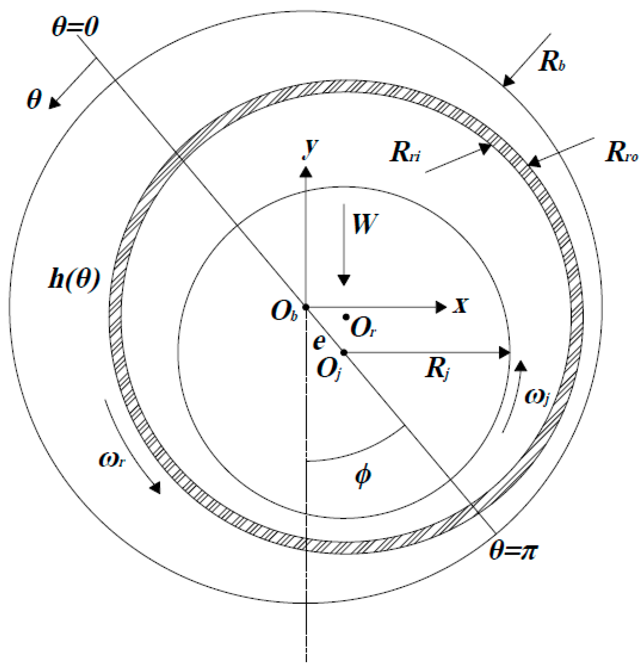
2.8. Floating Ring Bearings

A journal bearing that has a bushing (ring) that floats freely between the metal surfaces of the bearing and journal (Figure 17) is called a floating ring bearing (FRB) and is used to suppress shaft vibration [1]. The operating speed of the shaft produces an increase in the fluid temperature; therefore, the material of the floating ring must be appropriate because there is temperature transfer between the inner film and the outer film of the lubricant in rotating machinery that operates at high speeds, such as automotive turbochargers, aircraft turbines, and engines.
San Andrés [70] analyzed an FRB of an automotive turbocharger (TC) for the prediction of the pressure and temperature fields of the inner and outer films and the bushing temperature; they observed that the shaft was a heat source that quickly warmed the lubricant, particularly in the inner film. This made it necessary to have an adequate system of fluid flow to keep the lubricant in a liquid state because the floating ring developed a significant radial temperature gradient; at all shaft speeds—low and high—the thermal energy carried away by the lubricant streams was no less than 70% of the total energy input; the rest was conducted through the TC’s casing. San Andrés [71] validated nonlinear rotodynamic models of an FRB for the prediction of the forced dynamic response of a turbocharger; the ring speed and the out lubricant temperature showed a good agreement with experimental measurements. However, an increase in temperature was observed when the shaft speed increased, causing larger friction losses and a reduced lifetime of the lubricant and bushing.
Currently, magnetorheological fluids are used as smart lubricants in FRBs; by means of a magnetic field, these can be used to modify the fluid viscosity and add additional friction due to the adhesion of the steel particles on the bearing surface. Using the Herschel–Bulkley (HB) model, Wang [72] determined and analyzed the stiffness and damping coefficients of an FRB and sFRB (semi-floating ring bearing) with magnetorheological fluids as a lubricant; compared to an ordinary journal bearing, the MRF-lubricated FRB was more effective in changing the damping properties, and the power loss caused by friction was lower. In addition, the damping alterations caused by the external magnetic field were more prominent than the stiffness alterations for FRBs.
On the other hand, the particles adjacent to the bearing surface are the most affected by the magnetic field generated by the current in the coils. Therefore, the system stability can be analyzed by considering the fluid film as two layers of lubricant with different viscosities. Rao [73] analyzed a journal bearing with two lubricant layers between the journal and bearing and observed that the load capacity was the greatest when the lubricant layer with the highest viscosity was adjacent to the journal surface. However, if the lubricant layer with the highest viscosity was adjacent to the bearing surface, the journal bearing’s stability was higher.

2.9. Journal Bearing Lubricated with Magnetorheological Fluids

A magnetorheological fluid (MRF) is a smart or controllable fluid that modifies its rheological properties, such as its viscosity and yield stress, in a very short time when a magnetic field is applied. MRFs are mainly used in structural vibration control and power flow systems [74]. A magnetorheological (MR) fluid can be implemented in a variety of smart actuation systems, including optical polishing, fluid clutches, and aerospace, automotive, and civil damping applications in semi-active systems [75]. The Herschel–Bulkley model gives the MRF viscosity, which is very complex and incorporates an additional source of nonlinearity [76]. A simplification of the Herschel–Bulkley model is the Bingham viscosity model, which is characterized by its non-zero shear stress when the stress ratio is zero.
τ μ a γ ˙ = τ 0 + μ γ ˙
where τ is the shear stress, μ a is the non-Newtonian viscosity (local “apparent” viscosity), τ 0 is the yield stress, μ is the Newtonian dynamic viscosity, and γ ˙ is the shear rate.
Gertzos [77] modeled a journal bearing lubricated with an MRF in CFD and analyzed the effect of varying the L / D ratios and ε for various values of τ 0 ; the fluid viscosity was determined using the Bingam model for each yield stress. For any value of ε , Gertzos observed that the load-carrying capacity, film pressure, and frictional force were larger than those of a Newtonian fluid and increased as the yield stress τ 0 increased.
Bompos [74] modeled a journal bearing with an MRF (Figure 18) while considering the Bingham viscosity model with several values of L / D . They expressed the fluid viscosity as a function of the magnetic field intensity H :
μ a = μ + τ 0 H 𝜕 u 𝜕 y
The shear stress τ 0 with the magnetic field intensity H can be estimated with experimental data. Bompos solved the magnetic field intensity with a magnetostatic model in ANSYS MULTIPHYSICS, where the main load was the current density of the source, and they simultaneously determined the fluid viscosity by using (18) and used it in ANSYS Fluent. The load capacity increased when the magnetic field intensity was increased; however, the friction coefficient also increased, generating energy losses. Therefore, a suitable power source was necessary to generate a suitable magnetic field intensity. Bompos [78,79] carried out a theoretical and experimental analysis of a journal bearing lubricated with an MRF and NMRF (nanoMRF); they determined the dynamic coefficients of both fluids and compared them with those of Newtonian fluids. Their simulation and experiments showed that the magnetic field increased the stiffness and damping coefficients and the stability. These parameters were larger in the NMRF than in the MRF because the particle size of the paramagnetic particles inside the MRF’s volume played a significant role in its rheological behavior and physical properties; for example, the particle adhesion “cores” on the bearing surface generated changes in the attitude angle when the rotor’s operating speed was varied.
Wang [80] applied a linear regression method to experimentally determine the stiffness, damping, and added-mass coefficients of a floating ring bearing lubricated with an MRF and excited with two shakers. They concluded that the MRF modified the dynamic coefficients of the FRB when an external magnetic field was applied; the most affected coefficients were those in the outer film, while the inner film coefficients stayed constant. However, the dynamic coefficients of the FRB were sensitive to the bearing load due to the relatively small load capacity.

2.10. Aerostatic Bearings

The characteristics of aerostatic bearings are modified by varying the radial clearance C , the supply pressure P , and/or the supply orifice diameter d 0 (Figure 3); the bearing load capacity and the stiffness increase at high operation speeds [5,81]. Cui [3] transformed the Reynolds equation of a spherical gas bearing into a standard elliptic partial differential equation, which was solved by using the MATLAB PDE tool. Cui carried out a theoretical and experimental analysis of a spherical bearing lubricated with air and observed the following: Given C y d 0 , the radial force F r , the axial force F a , the radial stiffness K r , and axial stiffness K a increase for all ε as P increases. Given d 0 and P , F r and F a decrease for all ε , and K r and K a decrease for ε 0.7 and increase for ε > 0.7 as C increases. Given P and C , F r and F a increase for all ε , while K r and K a increase up to ε = 0.5 as d 0 increses. From the above, it can be concluded there are optimal values of C , d 0 , and P when designing aerostatic bearings.
Adding elements to an aerostatic bearing or making it hybrid also modifies its characteristics; Wilkes [82] implemented a double-layer wing foil (WF) configuration in an aerostatic bearing. The double-layer WF configuration influenced the stiffness, damping, and temperature of the bearing; the stiffness increased almost twice as much as with a single layer, and the damping also increased.
The CFD modeling of aerostatic bearings is similar to that of journal bearings but with several pressure inlets (pressure holes) and two pressure outlets (ends of the fluid film). Each feeding hole provides the same pressure, and the outlets are set to atmospheric pressure. However, it is possible to model only a fraction of the fluid film thickness with one pressure hole through an axisymmetric model, which reduces the computational cost. Von Osmanski [4] applied hybridization to a three-pad gas foil bearing (GFB) with radial injection and modeled a three-dimensional steady-state sub-model for an injector and a small part of the fluid film in the OpenFOAM CFD code. Von Osmanski observed that the load capacity increased and enhanced the OSI (onset speed of instability); according to Campbell diagrams, the OSI increased by 22%. In addition, the sub-synchronous vibration amplitude was reduced by approximately 66% for a medium level of imbalance and by approximately 20% for a high level of imbalance, with both occurring at the expense of a slightly increased synchronous amplitude.
The shapes of orifice chambers also influence the characteristics of aerostatic bearings; Gao [83] (Figure 19a) modeled the orifice chamber of an aerostatic bearing with CFD in ANSYS Fluent and observed the differences in the pressure distribution, load capacity, and axial stiffness among the different orifice chamber shapes. The above parameters were better with the cylindrical shape (c). In addition, the mass flow rates were the highest, and the vortices that appeared in the chambers were weakened when the fluid thickness decreased; however, the vortices in the chamber with rounded corners (e) were completely suppressed (Figure 19b). With CFD, Chen [81] analyzed an axisymmetric model of the shapes of orifice chambers and concluded that the vortices caused the gas temperature to increase, thus affecting the bearing performance and generating micro-vibrations due to the fluid injection. With different three-dimensional CFD models, Feng [84] determined that the use of an arc-hole bearing decreased the micro-vibrations and increased the stability by reducing the vortices. Therefore, the shapes of the chambers and the holes, as well as the hole diameter, are geometric variables that influence the performance of aerostatic bearings. The results of previous studies can be used as a starting point to design aerostatic bearings for high-speed light rotors.

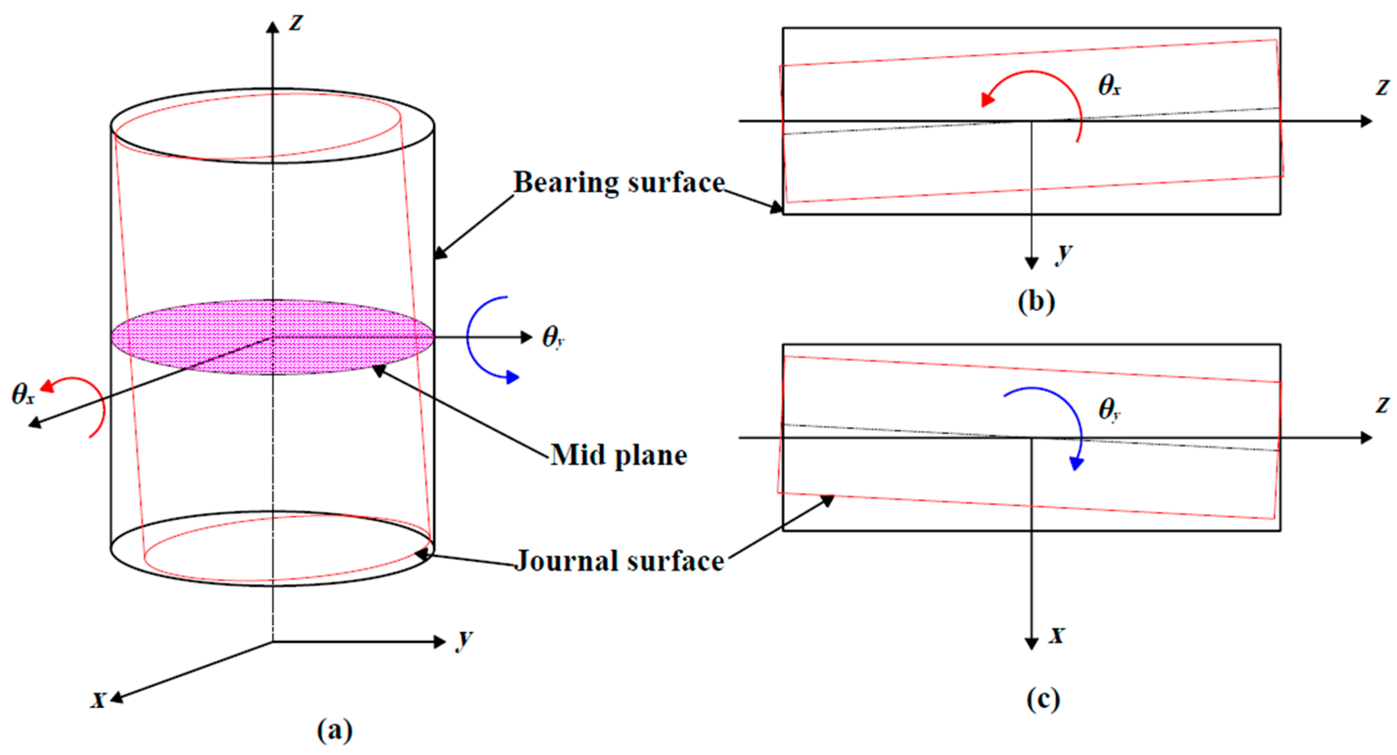
2.11. Journal Bearings with Misalignments

The misalignment of journal bearings is attributed to various factors, such as machining imperfections, mistakes in rotary machine assembly between bearings, an external force (load), or the rotor weight, which produce shaft deflection [85,86]. Therefore, the fluid film thickness is no longer uniform in the axial direction (Figure 20) because it decreases at the ends compared to the fluid film thickness at the bearing’s center [87]. The change in the fluid film thickness modifies the pressure distribution and increases the maximum pressure, thus producing a concentration of effort at the ends and changes in stability threshold [14].
Abdou [88] analyzed the effect of misalignment on the stability of a rotor–bearing system for several eccentricity ratios, misalignment direction angles, and misalignment degrees; they modified the equation for the fluid film to increase the degrees of freedom, and the Reynolds equation was solved by using the FDM. Abdou observed that low misalignment direction angles caused increases in the stability as the eccentricity ratio increased, while the misalignment degree had no significant effect on stability. Sun [89] observed that a greater shaft deflection produced a greater misalignment and a smaller fluid film thickness due to its weight. The load capacity, attitude angle, flow rate, and friction coefficient slightly changed, while the misalignment moment significantly increased when the eccentricity ratio increased.
The effects of the misalignment moment and misalignment direction angle were analyzed experimentally and numerically by Pierre [85]; he observed that the maximum temperature of the lubricant was located at the ends of the bearing, where the minimum fluid film thickness was found. The thermal effect influences the performance of the lubrication of a bearing with misalignments, as Sun [90] showed in an analysis of a journal bearing with a rough surface. Sun calculated the fluid film pressure and temperature, load-carrying capacity, end leakage flow rate, frictional coefficient, and misalignment moment with different angles of journal misalignment and surface roughness while considering the fluid viscosity–pressure relationship (VPR) and the thermal effect with various eccentricity ratios. The above parameters were significantly affected by the fluid VPR and the thermal effect when ε > 0.6 . Xiang [31] and Cai [33] numerically modeled a grooved coupled bearing with misalignments of four and five DOFs (degrees of freedom), respectively. They considered the transient contact pressure due to the deformation of the bearing surface and calculated the hydrodynamic, friction, and asperity contact forces as a result of the disturbing forces and moment caused by a propeller.
The static parameters of journal bearings with misalignments from the previous investigations were calculated with the Reynolds pressure equation by solving with the FDM or FEM with the 2D model of the fluid film thickness [18], which is given by
h = h 0 + Δ x + z Δ θ y cos θ + Δ y z Δ θ x sin θ
h 0 = c + e m 0 cos θ Φ m 0 + z θ y 0 cos θ θ x 0 sin θ
The Reynold equation is the same as that of the journal bearing and is also solved with the FEM or FDM, but with more pressure gradients because of the misalignment.
The 3D CFD modeling of journal bearings with misalignments is similar to that of journal bearings without misalignments, i.e., the same boundary conditions are configured, but the edges at the ends of the clearance that represent the journal surface are not concentric due to the misalignments (see Figure 20). CFD analysis of 3D models provides a better approximation of a real fluid model in transient or steady flow because more variables that affect the hydrodynamic lubrication of bearings with misalignments can be considered [91]. By using CFD, Zhang [92] analyzed the influence of the misalignment direction α , misalignment angle β , relative clearance ψ , length-to-diameter ratio L / D , diameter D , and rotational speed N on the ultimate load-carrying capacity F and the ultimate misalignment moment M . With the results obtained and the method provided by Zhang, suitable design parameters for a journal bearing while considering journal misalignment can be determined.
A misalignment also modifies the dynamic characteristics of a journal bearing; Jang [18] numerically calculated the stiffness and damping coefficients of a herringbone groove journal and thrust bearing in a spindle motor while considering misalignment. In the journal bearing, Jang observed that k x x , k x y = y x , c x x , and c y y were higher and that k y y   and   c x y = y x were smaller than those in bearings without misalignment. In the thrust bearing, the direct stiffness and damping coefficients were also increased, while the cross-coupled coefficients were not affected by the misalignment. However, the misalignment significantly increased the moment coefficients ( K θ x θ x and C θ x θ x ).

3. CFD Transient Analysis of Fluid Film Bearings with the Dynamic Mesh Technique

Steady-state or transient CFD analysis of bearings can be performed from the simplest model to the most complex by considering laminar or turbulent flow regimes according to the object of study. therefore, the computational time tends to increase due to the model complexity. Steady-state CFD analyses of journal bearings are mainly performed with known values of the eccentricity ratio [27] when it is desired to know the attitude angle of the journal, the maximum pressure, the load capacity, the friction force, and the surface deformation of the bearing, with the last parameter being modeled with the fluid–structure interaction (FSI). Shenoy [93] and Suddapalli [94] modeled a journal bearing with CFD and the FSI and analyzed the deformation of the bearing surface for different values of ε and L / D . They observed that the maximum pressure P m a x , the stress distribution, and the deformation of the bearing increased when ε or L / D was increased. Wodtke [95] analyzed journal and tilting-pad thrust bearings (TPTBs) in the laminar and turbulent flow regimes while considering cavitation for two saturation pressure p s a t values. Wodtke concluded that the minimum fluid film thickness h m i n , P m a x , and the maximum temperature T m a x strongly depended on the established flow regime and p s a t in both bearings. The laminar flow results showed that the p s a t value influenced the journal equilibrium position, but h m i n and P m a x of the lubricant were not influenced. The influence of the turbulence on the heat exchange in a TPTB was analyzed; the values of P m a x and T m a x on the tilting pads were higher and h m i n was smaller in the turbulent flow than in the laminar flow. Therefore, the turbulent flow increased the heat convection of the pad surface by raising T and increasing the thermal deformations of the pad.
Dhande [96] analyzed a journal bearing in CFD by using the FSI and considering the cavitation phenomenon and elasto-hydrodynamic effect; they observed that ε and ϕ were different between the rigid model and elastic model of a bearing due to the decrease in the pressure distribution and P m a x because of the effect of the elastic deformation in the bearing, which was a result of the increase in h , generating a pressure drop. Depending on the rotor’s operation conditions, a suitable lubricant can be an option for attenuating the deformation effects. Madhusudhanarao [28] modeled a journal bearing with two lubricant oils (SAE 20 and SAE 40) under the same operating conditions and observed that the deformation and P m a x were lower with SAE 20 than with SAE 40, which was attributed to the lower lubricant viscosity. A material with suitable properties is another option for decreasing the bearing deformation. Kalbande [97] analyzed the bearing deformation for two materials—polytetrafluoroethylene (PTFE) and carbon-fiber-reinforced PTFE (CFPTFE)—and observed that under the same operation conditions, the material with a higher elastic modulus (CFPTFE) reduced the deformation by 73.38% compared to PTFE. Liu [98] analyzed the journal’s equilibrium position in three elastic CFD–FSI models, with each one using a different material for the bearing: a Babbitt insert on a steel backing, a nylon insert on a steel backing, and unbacked nylon (Figure 21a). The results showed that the equilibrium position of the journal in the bearing with the material with the lowest Young’s modulus (unbacked nylon model) exceeded the radial circle clearance (Figure 21b) because the rotor weight generated a large deformation in the insert, thus reducing the load capacity compared to that in the other models.
The transient analysis of journal bearings is used to determine the locus of the journal center, hydrodynamic forces, and stiffness and damping coefficients when the equilibrium position is perturbed by an unbalanced force or a fixed or fluctuating external force due to the rotor load. In most CFD transient modeling, the dynamic mesh method is used to modify the nodal positions of the elements that form the lubricant fluid film. Therefore, a suitable algorithm of nodal motion that can keep the structured discretization of the mesh elements (Figure 22) is necessary to obtain reliable results and reduce the simulation time of transient-state rotor–bearing system models [99].
In ANSYS Fluent, the UDFs are used to determine the hydrodynamic forces and calculate and apply the nodal displacements in the transient analysis of simple models of journal or thrust bearings and rotor–bearing systems with/without misalignments and with any type of lubricant. Ngondi [100] proposed a mesh movement algorithm that was programmed with the UDF DEFINE_GRID_MOTION to determine and modify the nodal positions of an annular groove SFD, thus generating a CCO movement of the rotor, and F R and F T were computed with ε = 0.44 and ε = 0.9 . In an experimental rotor supported by two AMBs (active magnetic bearings) at the ends and an SFD in the shaft center, Ngondi determined the fluid forces of the SFD with (21) and compared them with the calculated numerical forces, showing a qualitative correlation.
F S F D = m e ¨ F A M B
Li [91] solved a flexible rotor–bearing model with misalignment by using the fourth-order Runge–Kutta method to determine the journal center and node displacements and then update the mesh. Li observed that the values of the maximum film pressure, friction torque, and misalignment moment markedly increased when the degree of misalignment increased. However, the oil film force and the attitude angle did not significantly vary with the misalignment. Cheqamahi [40] computed the nodal displacements by simultaneously solving the kinematic Equation (22) to move the journal to its static equilibrium position. The journal started from a concentric position with the bearing, where the initial conditions of the hydrodynamic forces F f l u i d and movement parameters ( s 0 and s 0 ˙ ) were zero; at each time step, the journal was moved, and the mesh was updated; then, the hydrodynamic forces were determined with (23). The simulation stopped when the hydrodynamic forces satisfied the force balance condition (11).
M s ¨ = M g + F f l u i d s ˙ = s 0 ˙ + s ¨ t s = s 0 + s ˙ t
F x = 0 L 0 2 π P sin θ d θ d z F y = 0 L 0 2 π P cos θ d θ d z
Li [101] modeled a journal bearing with four and eight axial grooves and determined the forces in each time step with (23) and the acceleration, velocity, and displacement components of the journal with the movement Equations (24)–(26), respectively.
M x ¨ = F x + M e ω 2 cos ω t M y ¨ = F y M g + M e ω 2 sin ω t
x ˙ t + t = x ˙ t + x ¨ t t y ˙ t + t = y ˙ t + y ¨ t t
x t + t = x t + x ˙ t t + 1 2 x ¨ t t 2 y t + t = y t + y ˙ t t + 1 2 y ¨ t t 2
Concli [102] used the methodology of Li [101] to determine the journal trajectory in a journal bearing for different load magnitudes and operating speeds of the rotor while considering the Kunz cavitation model. Concli computed the accelerations ( x ¨ t , y ¨ t ) while neglecting both the effect of force due to the eccentricity and the velocities ( x ˙ t ,   y ˙ t ) to determine the nodal displacements according to (27) and the hydrodynamic forces according to (23) in Scilab and OpenFOAM®, respectively.
x t + t = x t + x ¨ t t 2 y t + t = y t + y ¨ t t 2
The linearization of the hydrodynamic forces results from the consideration of only the first-order terms of the Taylor series expansion for a small amplitude of journal movement ( x , y , x ˙ , y ˙ ) when it is moved from the static equilibrium position ( x j , y j ) in x direction and y direction with constant perturbation velocities x ˙ and y ˙ , respectively. The hydrodynamic forces of Equation (23) in the x direction and y direction can be written, respectively, as
F x 1 = F x 0 k x x Δ x c x x Δ x ˙ F y 1 = F y 0 k y x Δ x c y x Δ x ˙ x d i r e c t i o n
F x 2 = F x 0 k x y Δ y c x y Δ y ˙ F y 2 = F y 0 k y y Δ y c y y Δ y ˙ y d i r e c t i o n
By applying a linear fit to the hydrodynamic forces, four linear expressions of force of the following form are obtained:
F x 1 = a 1 x + b 1 F y 1 = a 2 x + b 2
F x 2 = a 3 y + b 4 F y 2 = a 4 y + b 4
where the stiffness and damping coefficients are given by
k x x k x y k y x k y y = a 1 a 3 a 2 a 4 c x x c x y c y x c y y = b 1 F x 0 x ˙ b 3 F x 0 y ˙ b 2 F y 0 x ˙ b 4 F y 0 y ˙
The initial shock in the transient calculations occurs in the CFD solution of the hydrodynamic forces, which must be eliminated to apply the linear fit and then calculate the dynamic coefficients. Li [103] modeled and analyzed a TPJB in CFD Fluent by applying displacements from x j x , y j to x j + x , y j in the horizontal direction and from x j , y j y to x j , y j + y in the vertical direction. To remove the initial shock of the forces, Li considered a range of positions close to the equilibrium position, as well as their respective forces; with the linear fit, they computed the coefficients k i j and c i j . Li [104] linearly disturbed a journal’s equilibrium position and obtained the hydrodynamic forces of a journal bearing with a given eccentricity. They neglected the initial shock of the forces (Figure 23), and without applying the linear fit, they directly took the values of F x and F y with linear behavior to calculate the coefficients k i j and c i j according to the following expressions:
k x x k x y k y x k y y = F x x / x F x y / y F y x / x F y y / y
c x x c x y c y x c y y = F x x / x ˙ F x y / y ˙ F y x / x ˙ F y y / y ˙
Li [101] neglected the initial shock of the forces and applied the linear fit to obtain expressions such as (30) and (31); then, the coefficients were calculated with (32), where the displacements were applied from x j , y j to x j + x , y j and from x j , y j to x j , y j + y with different perturbation velocities. With the calculated coefficients, the linear forces were obtained with (35), and the nonlinear forces with the CCO movement of the journal were calculated with (23) in Fluent. The comparison of linear and nonlinear forces showed that they had a good agreement; however, there were differences, which were because only the first-order terms of the Taylor expansion were considered.
F x F y = F x 0 F y 0 + K   Δ x Δ y + C Δ x ˙ Δ y ˙
Bearing modeling with the dynamic mesh method, a nodal motion algorithm, and a structured mesh provides more reliable simulation results and more realistic rotor movement within a bearing from any starting position when computing the hydrodynamic forces.
This section described the modeling of journal bearings by using a dynamic mesh for transient or steady-state analysis; however, as could be seen, this type of modeling is also applicable to other bearings because the same algorithms can be used to determine or modify the equilibrium position of the journal.

4. Discussion

According to the previous review of the literature on the CFD modeling and analysis of journal, thrust, and aerostatic bearings, the characteristics, advantages, and disadvantages of each type of bearing (plain, grooved, texturized, with pockets, with tilting pads, with floating bushing, and lubricated with FMR) are discussed below.
Journal bearings are widely used due to their long life, reduced wear, and high load capacity [1]; however, they are more prone to instability problems at high operating speeds because of the self-excited rotor vibrations (known as whirl and whip phenomena) resulting from the fluid dynamic forces generated in the bearing [105]. To increase the stability range, the bearing surface is modified by adding textures, pockets, and/or grooves with or without external pressurization, dividing the lubricant film by means of a floating bushing, using smart fluids, or incorporating mobile pads to modify the lubricant film thickness and the pressure field [10,11,35,42,43,50,51,53,54,70,75,76,82,84,88] because the pressure distribution is concentrated on surfaces of a smaller area, resulting in a greater load capacity, lower eccentricity, and greater attitude angle. In addition, the cross-dynamic coefficients decrease, which contributes to the expansion of the stability. To carry out a stability analysis of a rotor–bearing system, the dynamic coefficients must be determined, and these are a function of the pressure field given by the journal position and can be numerically determined with linear or nonlinear perturbations while considering high-order terms of the Taylor expansion [8] for finite bearings.
The pressure field and the static and dynamic parameters of a bearing can be determined according to the short and long bearing theories, but each considers only a pressure gradient in one coordinate system [8,12,13,14,15,17,18,19,20]; therefore, the static and dynamic parameters are an excellent approximation. The pressure field of a finite bearing is more reliable because it considers both pressure gradients; however, its computation is not easy (see Equation (22)), even though the analysis is considered to be in the steady state. Analytical methods for solving the Reynolds pressure equation and determining the static and dynamic characteristics of a finite journal bearing are complex [9,10,11], as they are particular solutions, even for the simplest model, where the number of variables is limited. However, analytical methods provide dimensionless “general solutions” for any input parameter ( ε , L / D , N , μ , ρ , and/or M ). Therefore, numerical methods such as the FEM, the FDM, or CFD software are used, with the latter being the most widely used because a larger number of variables that affect the fluid dynamics of lubrication can be used, in addition to the flexibility in setting the boundary and operating conditions. However, the computation time of the simulations is expensive because the bearing’s pressure field is obtained from the solution of the Navier–Stokes equations. Solving the Reynolds equation using FEM or FDM codes is faster because it is simpler than the Navier–Stokes equations (CFD software) and, thus, takes less computation time. However, the development of the code can be tedious and complex because basic programming knowledge is necessary; in addition, if irregular geometries exist, then the elements of the fluid film discretization will not generate a structured mesh. This produces uncertainties in the results of the pressure fields; therefore, methods that consider the elements’ skewness must be applied to improve the accuracy of the calculations [15].
The grooves in a bearing distribute the pressure only to the surfaces (pads) adjacent to them [36,37,38,39], which increases the load capacity and the stability threshold because the cross-coefficients of stiffness and damping are reduced for a given rotor speed. Reductions in the temperature of the fluid and the friction torque are other benefits of grooved bearings; in addition, the wear is reduced in drilling machinery or ship rotors because the grooves are outlets for impurities in the lubricant [32,42]. However, the size, depth, and number of grooves must be considered because the friction losses increase [35] and the multilobe effect decreases [37], thus reducing the load capacity mainly at high eccentricities. Therefore, if the geometric parameters of the grooves are not suitable, a new geometry of the bearing will result, and the characteristics will be modified, which will affect the performance of the grooved bearing. It will begin to behave as a plain journal bearing because the pressure distribution becomes inequal on each lobe, with the peak pressure value shifting toward the lobe where the film thickness is lowest; grooved bearings should be used at high operating speeds and with light loads. Texturized bearings reduce friction and increase the load capacity when the texture is partially located in the convergent zone, which diminishes the absolute value of the cross-stiffness coefficients, thus increasing the stability threshold and reducing the self-excited vibration of rotors [50]. The temperature, pressure, and size of bubbles generated through fluid cavitation are reduced [44]; therefore, the temperature and the pressure drop of the lubricant fluid film decrease, thus improving the load capacity. However, a partial texture in the convergent zone is suitable when the rotor rotates in only one direction; otherwise, its positive effect will be smaller. In addition, textures should not be added on all surfaces because the full texturing reduces pressure and is ineffective in generating load capacity [51], as the pressure is only generated in the convergent zone.
Pockets and recesses improve the static and dynamic characteristics of a hybrid journal bearing because the pressure distribution and load capacity are greater than those of hydrostatic and hydrodynamic bearings. The shape, quantity, and distribution of the texture affect the fluid thickness, temperature, flow rate, and dynamic coefficients of the bearings [54,55,56]. This is attributed to the fact that the pressure distribution changes and the maximum pressure increases, which positively affects the equilibrium position, i.e., the load capacity increases. However, these bearings should also be used at high operating speeds and with a light load. In addition, the pocket number should not be high because the multilobe effect decreases and the bearing begins to behave as a plain journal bearing.
Thrust bearings are widely used in drilling and high-precision machinery; therefore, a smooth axial displacement and low fluid temperature are necessary [57]. Additional elements, such as pockets, grooves, tilting pads, and/or compression systems for the lubricant film, improve the static and dynamic characteristics of the thrust bearing. Pockets reduce the friction and temperature of the lubricant, and grooves increase the maximum pressure and modify the pressure distribution [59,60], which produces an increase in the bearing stiffness and the load capacity. In addition, if the fluid film is pressurized, the lubricant temperature decreases due to the fluid circulation [58]. However, the location of additional elements must be taken into account to obtain positive effects, such as low shear stress and friction; otherwise, the shear stress and the temperature can be increased, affecting the lubricant properties and decreasing the load capacity.
TPJBs are often used when a greater stability is required and preloading is possible in order to increase the stiffness by changing the pad’s position and orientation by means of mechanical and electrical actuators or through pressurization [1,2]. The power losses and pad temperatures are reduced when pockets and steps are added [68]; however, small changes in the pads’ position and orientation generate large changes in the dynamic coefficients and in the equilibrium position, thus contributing to a higher shear stress. The CFD modeling of TPJBs is more complex because the pads also move with angular displacement; it is harder to find the journal’s equilibrium position because the displacement of each pad is different from the others. Therefore, the fluid–structure interaction is commonly used to apply the displacement of the pads because the surface deformation is considered in the analysis [64,66,67,68,69].
Journal bearings become floating bushing bearings when a floating bushing is added, which increases the stiffness and damping and attenuates the vibrations at high operating speeds. However, this double layer of lubricant causes the internal fluid film to be the hottest due to the high speeds of the fluid in that layer [19], thus affecting the lubricant’s physical properties and causing deformation of the bushing. Therefore, a suitable bushing material and cooling system are necessary.
MRFs are used to increase the load capacity, dynamic coefficients, and stability threshold of a journal bearing [74,77,78,79,80]. In addition, MRFs are smart fluids, so their dynamic coefficients can be controlled with the magnetic field’s intensity. However, it must be taken to account that MRFs increase the temperature and friction due to the formation of cores in the bearing surface or the floating bushing, which demands a greater power supply and a cooling system for the operation of the bearing. The heat produced by the coils must be considered because heat is transferred to the fluid film, affecting its lubricating properties.
The load capacity, stiffness, and damping of aerostatic bearings are sensitive to the feed hole diameter, clearance, supply pressure [3,5,81], and additional elements, such as the wing foil [4,82]. The recess shape also modifies the load capacity and reduces the fluid vortices, while the radial injection increases the onset speed of instability (OSI) and reduces the sub-synchronous vibration amplitudes. Aerostatic bearings are used for light loads at high speeds; therefore, the constant objective is to increase their load capacity and dynamic coefficients. In general, the load capacity and stiffness of aerostatic bearings are not as high as those of journal bearings due to the high compressibility of the gas and the high power losses. Therefore, an optimal clearance, feed hole diameter, and supply pressure must be determined to increase the load capacity and stiffness. Another option is adding a spring element with a uniform stiffness distribution, which allows the stiffness to be increased or even doubled. This is suitable but generates mechanical interference when the shaft is not rotating; therefore, the startup torque increases. Finally, the hybridization of aerostatic bearings can also improve their characteristics—mainly the stability threshold—and can suppress the wear and mechanical interference when starting and stopping the rotor.
Misalignments modify the pressure distribution of the fluid film of a journal bearing because the fluid film thickness at the ends is lower; therefore, the values of pressure and friction were increased, generating higher stresses and temperatures, which produced surface deformation of the journal bearing and a negative change in its static and dynamic parameters [14,85,88]. Misalignments will always be present in journal bearings due to an external load or the rotor’s weight [85,86], even if the rotor–bearing system’s assembly is correct. Therefore, misalignments must be considered in the analysis of bearings to generate an appropriate design that provides a long bearing life and good rotor performance. In addition, misalignments increase some dynamic coefficients and decrease others [18], which may seem positive, but it is not because the temperature and the concentration of effort increase, thus generating surface deformation and fluid degradation.
CFD modeling in ANSYS Fluent is an excellent option for the steady- and transient-state analysis of bearings because it allows a larger number of variables and phenomena that influence the tribological behavior of fluid film under different operating conditions to be considered when calculating the static and dynamic parameters of a bearing via mesh updates [27]. Mesh nodal movement algorithms are essential in the steady- and transient-state analysis of bearings [40,77,91,99,100,101,102,104] because they keep the mesh quality in each mesh update, thus providing reliable results and reducing the simulation time during the analysis. Therefore, a journal’s equilibrium position, load capacity, friction force, flow rate, dynamic coefficients, and other bearing parameters can be computed directly in ANSYS Fluent or together with UDFs for any rotor weight or journal eccentricity rate while considering different bearing materials and geometries, as well as models with different viscosities, external pressurization, surface temperatures, and deformations that depict a more realistic model of any type of bearing or rotor–bearing system [93,94,95,96]. However, the computing time is very high and better computer equipment is required. In addition, compared to the analytical solutions and numerical codes (FEM and FDM) that can be developed in open-access software, ANSYS Fluent is more expensive but very powerful because it is possible to parameterize input or output variables, such as the geometry, fluid properties, pressure, temperature, and others. In addition, Fluent needs UDFs to calculate variables such as the hydrodynamic and friction forces and needs movement algorithms to move surfaces, calculate the surface deformation, or analyze MR fluids; thus, it is necessary to interact with other ANSYS modules.
In general, the characteristics and applications of the fluid film bearings reviewed in this article are shown in the Table 2. In addition, the level of difficulty for modeling the fluid film bearings is indicated; However, from the literature reviewed, for the aerostatic and floating bushing bearings, modeling using CFD codes is preferred, or only one feed hole is modeled in aerostatic bearings.

5. Conclusions

According to the literature review, each type of bearing has specific advantages over the others. However, the disadvantages are also noticeable—mainly in terms of the load capacity, threshold stability, and power and temperature losses when the eccentricity ratios (or weight of the rotor) are high. Therefore, more comprehensive analyses of fluid film bearings that consider more variables should be developed to improve their design and performance.
The external pressurization of the lubricant fluid film of a bearing should also be considered in the analysis of the different types of bearings investigated here because the pressurization increases the load capacity and stiffness; therefore, it could reduce the disadvantages of the texture, floating bushing, grooves, pockets, tilting pads, and others while preserving and even increasing the stability.
New low-friction bearing designs and better cooling and pressurization systems also need to be developed to reduce the power and temperature losses and increase the load capacity and stability while providing low energy consumption to achieve higher operating speeds. The friction and particle adhesion of MRFs in journal bearing lubricated with MRFs should also be reduced; a hybridization (combination) of the bearings investigated here could possibly improve their static and dynamic characteristics, and this still needs to be investigated.
The areas of opportunity in bearing analysis are evident because it is necessary to consider more variables that affect the tribological behavior of fluids to provide a more realistic and complete analytical and/or numerical model of a bearing or rotor–bearing system.
On the other hand, when the equilibrium position of a journal, the dynamic coefficients, and the other parameters of a bearing should be determined in ANSYS Fluent, transient analysis consumes much computing time; therefore, new algorithms that optimize the computing time or a parameterization of the time steps should be developed to accelerate the movement of the journal center to reach the equilibrium position without causing a numerical failure or a negative volume of the grids.
In transient analysis, mesh moving methods based on structured grids reduce the risks of numerical failures and a negative volume of the grids and accelerate the updating of the grid nodal positions; therefore, in transient analyses involving mesh updating, they must be used.
Although CFD modeling in ANSYS Fluent costs much computing time and requires additional UDFs to determine some static and dynamic parameters, modeling in this software is relatively easy, and the programming of UDFs only requires basic programming knowledge.
CFD analysis with numerical codes (FEM and FDM) consumes less computing time; however, most simulations are used to model planar domains of a fluid, i.e., 2D meshes, and their programming is extensive and requires advanced knowledge of numerical methods.
Finally, better methods for identifying static and dynamic parameters should be proposed in numerical and experimental research while considering the nonlinearity of hydrodynamic forces.

Author Contributions

Conceptualization, D.P.-V., J.C.-O. and C.M.-V.; methodology, D.P.-V., J.C.-O. and V.I.R.-R.; software, D.P.-V., A.B.-O. and R.C.-A.; validation, D.P.-V., C.M.-V. and V.I.R.-R.; formal analysis, D.P.-V., J.C.-O. and V.I.R.-R.; investigation, D.P.-V., J.C.-O. and A.B.-O.; resources, D.P.-V., S.J.L.-D. and R.C.-A.; data curation, D.P.-V., J.C.-O. and R.C.-A.; writing—original draft preparation, D.P.-V., J.C.-O. and S.J.L.-D.; writing—review and editing, D.P.-V., J.C.-O. and A.B.-O.; visualization, R.C.-A., C.M.-V. and S.J.L.-D.; supervision, D.P.-V., J.C.-O. and C.M.-V.; project administration, D.P.-V., J.C.-O. and A.B.-O.; funding acquisition, D.P.-V., J.C.-O. and A.B.-O. All authors have read and agreed to the published version of the manuscript.

Funding

This research received no external funding.

Data Availability Statement

Not applicable.

Conflicts of Interest

The authors have declared that there are no conflicts of interest in this manuscript.

References

  1. Hori, Y. Hydrodynamic Lubrication, 1st ed.; Springer, Ed.; Yokendo Ltd.: New York, NY, USA, 2002; ISBN 104-431-27898-2. [Google Scholar]
  2. Szeri, A.Z. Fluid Film Lubrication. Theory & Design, 1st ed.; The Press Syndicate of the University of Cambridge: Cambridge, UK, 1998; ISBN 0 521 48100 7. [Google Scholar]
  3. Cui, H.; Xia, H.; Lei, D.; Zhang, X.; Jiang, Z. A Calculation Method to Investigate the Effects of Geometric Parameters and Operational Conditions on the Static Characteristics of Aerostatic Spherical Bearings. J. Tribol. 2019, 141, 021101. [Google Scholar] [CrossRef]
  4. Von Osmanski, S.; Santos, I.F. Gas Foil Bearings with Radial Injection: Multi-Domain Stability Analysis and Unbalance Response. J. Sound Vib. 2021, 508, 116177. [Google Scholar] [CrossRef]
  5. Song, L.; Cheng, K.; Ding, H.; Chen, S. Analysis on Discharge Coefficients in FEM Modeling of Hybrid Air Journal Bearings and Experimental Validation. Tribol. Int. 2018, 119, 549–558. [Google Scholar] [CrossRef]
  6. Naïmi, S.; Chouchane, M.; Ligier, J.L. Steady State Analysis of a Hydrodynamic Short Bearing Supplied with a Circumferential Groove. Comptes Rendus Mec. 2010, 338, 338–349. [Google Scholar] [CrossRef]
  7. Weißbacher, C.; Schellnegger, C.; John, A.; Buchgraber, T.; Pscheidt, W. Optimization of Journal Bearing Profiles with Respect to Stiffness and Load-Carrying Capacity. J. Tribol. 2014, 136, 031709. [Google Scholar] [CrossRef]
  8. Miraskari, M.; Hemmati, F.; Gadala, M.S. Nonlinear Dynamics of Flexible Rotors Supported on Journal Bearings—Part I: Analytical Bearing Model. J. Tribol. 2018, 140, 021704. [Google Scholar] [CrossRef]
  9. Sfyris, D.; Chasalevris, A. An Exact Analytical Solution of the Reynolds Equation for the Finite Journal Bearing Lubrication. Tribol. Int. 2012, 55, 46–58. [Google Scholar] [CrossRef]
  10. Chasalevris, A.; Sfyris, D. On the Analytical Evaluation of the Lubricant Pressure in the Finite Journal Bearing. Proc. ASME Des. Eng. Tech. Conf. 2012, 1, 661–671. [Google Scholar] [CrossRef]
  11. Chasalevris, A.; Sfyris, D. Evaluation of the Finite Journal Bearing Characteristics, Using the Exact Analytical Solution of the Reynolds Equation. Tribol. Int. 2013, 57, 216–234. [Google Scholar] [CrossRef]
  12. Goodwin, M.J.; Ogrodnik, P.J.; Roach, M.P.; Fang, Y. Calculation and Measurement of the Stiffness and Damping Coefficients for a Low Impedance Hydrodynamic Bearing. J. Tribol. 1997, 119, 57–63. [Google Scholar] [CrossRef]
  13. Majumdar, B.C.; Pai, R.; Hargreaves, D.J. Analysis of Water-Lubricated Journal Bearings with Multiple Axial Grooves. Proc. Inst. Mech. Eng. Part J J. Eng. Tribol. 2004, 218, 135–146. [Google Scholar] [CrossRef]
  14. Antonio, G.A. Investigación Analítica y Numérica de Las Propiedades Dinámicas de Chumaceras Hidrodinámicas Con y Sin Desalineamiento; Instituto Politécnico Nacional: Mexico City, Mexico, 2006. [Google Scholar]
  15. Han, Y.; Xiong, S.; Wang, J.; Wang, Q.J. A New Singularity Treatment Approach for Journal-Bearing Mixed Lubrication Modeled by the Finite Difference Method with a Herringbone Mesh. J. Tribol. 2016, 138, 011704. [Google Scholar] [CrossRef]
  16. Miraskari, M.; Hemmati, F.; Gadala, M.S. Nonlinear Dynamics of Flexible Rotors Supported on Journal Bearings—Part II: Numerical Bearing Model. J. Tribol. 2018, 140, 021705. [Google Scholar] [CrossRef]
  17. Sayed, H.; El-Sayed, T.A. A Novel Method to Evaluate the Journal Bearing Forces with Application to Flexible Rotor Model. Tribol. Int. 2022, 173, 107593. [Google Scholar] [CrossRef]
  18. Jang, G.H.; Kim, Y.J. Calculation of Dynamic Coefficients in a Hydrodynamic Bearing Considering Five Degrees of Freedom for a General Rotor-Bearing System. J. Tribol. 1999, 121, 499–505. [Google Scholar] [CrossRef]
  19. San Andres, L. Extended Finite Element Analysis of Journal Bearing Dynamic Forced Performance to Include Fluid Inertia Force Coefficients. In Proceedings of the ASME International Mechanical Engineering Congress and Exposition, Houston, TX, USA, 9–15 November 2012; pp. 1–9. [Google Scholar]
  20. Kang, Y.; Shi, Z.; Zhang, H.; Zhen, D.; Gu, F. A Novel Method for the Dynamic Coefficients Identification of Journal Bearings Using Kalman Filter. Sensors 2020, 20, 565. [Google Scholar] [CrossRef]
  21. Meruane, V.; Pascual, R. Identification of Nonlinear Dynamic Coefficients in Plain Journal Bearings. Tribol. Int. 2008, 41, 743–754. [Google Scholar] [CrossRef]
  22. Xing, C.; Braun, M.J.; Li, H. Damping and Added Mass Coefficients for a Squeeze Film Damper Using the Full 3-D Navier-Stokes Equation. Tribol. Int. 2010, 43, 654–666. [Google Scholar] [CrossRef]
  23. Panday, K.M.; Choudhury, P.L.; Kumar, N.P. Numerical Unsteady Analysis of Thin Film Lubricated Journal Bearing. Int. J. Eng. Technol. 2012, 4, 185–191. [Google Scholar] [CrossRef]
  24. Manshoor, B.; Jaat, M.; Izzuddin, Z.; Amir, K. CFD Analysis of Thin Film Lubricated Journal Bearing. Procedia Eng. 2013, 68, 56–62. [Google Scholar] [CrossRef]
  25. Balasoiu, A.M.; Braun, M.J.; Moldovan, S.I. A Parametric Study of a Porous Self-Circulating Hydrodynamic Bearing. Tribol. Int. 2013, 61, 176–193. [Google Scholar] [CrossRef]
  26. Gao, G.; Yin, Z.; Jiang, D.; Zhang, X. Numerical Analysis of Plain Journal Bearing under Hydrodynamic Lubrication by Water. Tribol. Int. 2014, 75, 31–38. [Google Scholar] [CrossRef]
  27. Zhang, X.; Yin, Z.; Gao, G.; Li, Z. Determination of Stiffness Coefficients of Hydrodynamic Water-Lubricated Plain Journal Bearings. Tribol. Int. 2015, 85, 37–47. [Google Scholar] [CrossRef]
  28. Madhusudhanarao, G.N.V.; Nagabhaskar, C. Design and CFD Analysis of Bearing with Different Lubricants. Int. J. Adv. Sci. Res. Eng. Trends 2020, 5, 84–92. [Google Scholar]
  29. Kyrkou, M.E.; Nikolakopoulos, P.G. Simulation of Thermo-Hydrodynamic Behavior of Journal Bearings, Lubricating with Commercial Oils of Different Performance. Simul. Model. Pract. Theory 2020, 104, 102128. [Google Scholar] [CrossRef]
  30. ANSYS. ANSYS. ANSYS Fluent Theory Guide 15. In ANSYS Fluent 15; ANSYS: Canonsburg, PA, USA, 2013. [Google Scholar]
  31. Xiang, G.; Wang, J.; Zhou, C.; Shi, Y.; Wang, Y.; Cai, J.; Wang, C.; Jin, D.; Han, Y. A Tribo-Dynamic Model of Coupled Journal-Thrust Water-Lubricated Bearings under Propeller Disturbance. Tribol. Int. 2021, 160, 107008. [Google Scholar] [CrossRef]
  32. Tang, D.; Xiang, G.; Guo, J.; Cai, J.; Yang, T.; Wang, J.; Han, Y. On the Optimal Design of Staved Water-Lubricated Bearings Driven by Tribo-Dynamic Mechanism. Phys. Fluids 2023, 35, 093611. [Google Scholar] [CrossRef]
  33. Cai, J.; Xiang, G.; Li, S.; Guo, J.; Wang, J.; Chen, S.; Yang, T. Mathematical Modeling for Nonlinear Dynamic Mixed Friction Behaviors of Novel Coupled Bearing Lubricated with Low-Viscosity Fluid. Phys. Fluids 2022, 34, 093612. [Google Scholar] [CrossRef]
  34. Fernandes, N.; Shenoy, S.B.; Pai, R.B.; Pai, R.S.; Rao, S.D. Evaluation of Stiffness and Damping Coefficients of Multiple Axial Groove Water Lubricated Bearing Using Computational Fluid Dynamics. World Acad. Sci. Eng. Technol. 2012, 6, 876–881. [Google Scholar]
  35. Christiansen, C.K.; Walther, J.H.; Klit, P.; Vølund, A. Investigation of Journal Orbit and Flow Pattern in a Dynamically Loaded Journal Bearing. Tribol. Int. 2017, 114, 450–457. [Google Scholar] [CrossRef]
  36. Rakhonde, B.N.; Suryawanshi, S.R. CFD Analysis of Hydrodynamic Journal Bearing. Int. J. Manuf. Mater. Process. 2018, 4, 23–29. [Google Scholar]
  37. Dhande, D.Y.; Lanjewar, G.H.; Pande, D.W. Implementation of CFD–FSI Technique Coupled with Response Surface Optimization Method for Analysis of Three-Lobe Hydrodynamic Journal Bearing. J. Inst. Eng. Ser. C 2019, 100, 955–966. [Google Scholar] [CrossRef]
  38. Ren, G. A New Method to Calculate Water Film Stiffness and Damping for Water Lubricated Bearing with Multiple Axial Grooves. Chin. J. Mech. Eng. Engl. Ed. 2020, 33, 72. [Google Scholar] [CrossRef]
  39. Ren, G.; Auger, G. Water Film Stiffness and Damping Analysis of Water Lubricated Bearings with Multiple Axial Grooves for Hydro Turbines. In Proceedings of the International Conference Hydro, Incheon, Republic of Korea, 21–26 August 2016; pp. 1–16. [Google Scholar]
  40. Moradi Cheqamahi, J.; Nili-Ahmadabadi, M.; Akbarzadeh, S.; Saghafian, M. Numerical Analysis of Turbocharger’s Bearing Using Dynamic Mesh. J. Appl. Fluid Mech. 2016, 9, 2545–2557. [Google Scholar] [CrossRef]
  41. Zhai, L.; Kitauchi, S.; Kazuyoshi, M.; Zhengwei, W. Study on the Flow Stability and Dynamic Characteristics of a Water Bearing. In Proceedings of the 2014 ISFMFE—6th International Symposium on Fluid Machinery and Fluid Engineering, Wuhan, China, 22–22 October 2014. [Google Scholar] [CrossRef]
  42. Bai, C.; Zheng, D.; Hure, R.; Saleh, R.; Carvajal, N.; Morrison, G. The Impact of Journal Bearing Wear on an Electric Submersible Pump in Two-Phase and Three-Phase Flow. J. Tribol. 2019, 141, 051702. [Google Scholar] [CrossRef]
  43. Xiang, G.; Yang, T.; Guo, J.; Wang, J.; Liu, B.; Chen, S. Optimization Transient Wear and Contact Performances of Water-Lubricated Bearings under Fluid-Solid-Thermal Coupling Condition Using Profile Modification. Wear 2022, 502–503, 204379. [Google Scholar] [CrossRef]
  44. Meng, F.M.; Zhang, L.; Long, T. Effect of Groove Textures on the Performances of Gaseous Bubble in the Lubricant of Journal Bearing. J. Tribol. 2017, 139, 031701. [Google Scholar] [CrossRef]
  45. Gu, C.; Meng, X.; Zhang, D.; Xie, Y. Transient Analysis of the Textured Journal Bearing Operating with the Piezoviscous and Shear-Thinning Fluids. J. Tribol. 2017, 139, 051708. [Google Scholar] [CrossRef]
  46. Yamada, H.; Taura, H.; Kaneko, S. Numerical and Experimental Analyses of the Dynamic Characteristics of Journal Bearings with Square Dimples. J. Tribol. 2018, 140. [Google Scholar] [CrossRef]
  47. Filho, F.; Bottene, A.C.; Silva, E.J.; Nicoletti, R. Static Behavior of Plain Journal Bearings with Textured Journal—Experimental Analysis. Tribol. Int. 2021, 159, 106970. [Google Scholar] [CrossRef]
  48. Jang, G.H.; Yoon, J.W. Nonlinear Dynamic Analysis of a Hydrodynamic Journal Bearing Considering the Effect of a Rotating or Stationary Herringbone Groove. J. Tribol. 2002, 124, 297–304. [Google Scholar] [CrossRef]
  49. Liu, H.; Jurkschat, T.; Lohner, T.; Stahl, K. Determination of Oil Distribution and Churning Power Loss of Gearboxes by Finite Volume CFD Method. Tribol. Int. 2017, 109, 346–354. [Google Scholar] [CrossRef]
  50. Rebufa, J.; Thouverez, F.; Le Guyadec, E.; Mazuyer, D. Nonlinear Effects of Surface Texturing on the Performance of Journal Bearings in Flexible Rotordynamic Systems. J. Tribol. 2017, 139, 051705. [Google Scholar] [CrossRef]
  51. Senatore, A.; Rao, T.V.V.L.N. Partial Slip Texture Slider and Journal Bearing Lubricated with Newtonian Fluids: A Review. J. Tribol. 2018, 140, 040801. [Google Scholar] [CrossRef]
  52. Nie, T.; Yang, K.; Zhou, L.; Wu, X.; Wang, Y. CFD Analysis of Load Capacity of Journal Bearing with Surface Texture. Energy Rep. 2022, 8, 327–334. [Google Scholar] [CrossRef]
  53. Guo, Z.; Hirano, T.; Kirk, R.G. Application of CFD Analysis for Rotating Machinery—Part I: Hydrodynamic, Hydrostatic Bearings and Squeeze Film Damper. J. Eng. Gas Turbines Power 2005, 127, 445–451. [Google Scholar] [CrossRef]
  54. Fu, G.; Untaroiu, A. A Study of the Effect of Various Recess Shapes on Hybrid Journal Bearing. J. Fluids Eng. 2017, 139, 061104. [Google Scholar] [CrossRef]
  55. Rahmani, F.; Pandey, R.K.; Dutt, J.K. Performance Studies of Powder-Lubricated Journal Bearing Having Different Pocket Shapes at Cylindrical Bore Surface. J. Tribol. 2018, 140, 031704. [Google Scholar] [CrossRef]
  56. Nicodemus, E.R.; Sharma, S.C. A Study of Worn Hybrid Journal Bearing System with Different Recess Shapes under Turbulent Regime. J. Tribol. 2010, 132, 041704. [Google Scholar] [CrossRef]
  57. Wu, H.; Huang, Y.; Cui, H.; Rong, Y. A Passive Compensated Method with Hydraulic Transmission for Static Infinite Stiffness of Thrust Bearing. Tribol. Int. 2021, 163, 107193. [Google Scholar] [CrossRef]
  58. Wasilczuk, M.; Rotta, G. Modeling Lubricant Flow between Thrust-Bearing Pads. Tribol. Int. 2008, 41, 908–913. [Google Scholar] [CrossRef]
  59. Brajdic-Mitidieri, P.; Gosman, A.D.; Ioannides, E.; Spikes, H.A. CFD Analysis of a Low Friction Pocketed Pad Bearing. J. Tribol. 2005, 127, 803–812. [Google Scholar] [CrossRef]
  60. Heinrichson, N.; Santos, I.F. Reducing Friction in Tilting-Pad Bearings by the Use of Enclosed Recesses. J. Tribol. 2008, 130, 011009. [Google Scholar] [CrossRef]
  61. Rao, T.V.V.L.N. Analysis of Single-Grooved Slider and Journal Bearing with Partial Slip Surface. J. Tribol. 2010, 132, 014501. [Google Scholar] [CrossRef]
  62. Han, D.; Bi, C.; Chen, C.; Yang, J. Dynamic Coefficients of Tilting Pad Bearing by Perturbing the Turbulence Model. Appl. Sci. 2022, 12, 6348. [Google Scholar] [CrossRef]
  63. Suh, J.; Palazzolo, A. Three-Dimensional Dynamic Model of TEHD Tilting-Pad Journal Bearing-Part I: Theoretical Modeling. J. Tribol. 2015, 137, 041703. [Google Scholar] [CrossRef]
  64. Conti, R.; Frilli, A.; Galardi, E.; Meli, E.; Nocciolini, D.; Pugi, L.; Rindi, A.; Rossin, S. An Efficient Quasi-3D Rotordynamic and Fluid Dynamic Model of Tilting Pad Journal Bearing. Tribol. Int. 2016, 103, 449–464. [Google Scholar] [CrossRef]
  65. Lou, M.; Bareille, O.; Chen, W.; Xu, X. Experimental and Numerical Investigation on the Performance of Fluid Pivot Journal Bearing in One-Sided Floating State. Tribol. Int. 2019, 138, 353–364. [Google Scholar] [CrossRef]
  66. Suh, J.; Palazzolo, A. Three-Dimensional Dynamic Model of TEHD Tilting-Pad Journal Bearing—Part II: Parametric Studies. J. Tribol. 2015, 137, 041704. [Google Scholar] [CrossRef]
  67. Liu, B.; Wang, W.; Gao, J.; Zhang, J. Influence of Bearing Load on the Performance of Tilting-Pad Journal Bearing under High Surface Velocity. In Proceedings of the Turbo Expo: Power for Land, Sea, and Air, Charlotte, NC, USA, 26–30 June 2017. [Google Scholar]
  68. Yang, J.; Palazzolo, A. Power Loss Reduction for Tilt Pad Journal Bearings Utilizing Pad Pockets and Steps. Tribol. Int. 2021, 159, 106993. [Google Scholar] [CrossRef]
  69. Varela, A.C.; García, A.B.; Santos, I.F. Modelling of LEG Tilting Pad Journal Bearings with Active Lubrication. Tribol. Int. 2017, 107, 250–263. [Google Scholar] [CrossRef]
  70. San Andres, L.; Barbarie, V.; Bhattacharya, A.; Gjika, K. On the Effect of Thermal Energy Transport to the Performance of (Semi) Floating Ring Bearing Systems for Automotive Turbochargers. J. Eng. Gas Turbines Power 2012, 134, 102507. [Google Scholar] [CrossRef]
  71. San Andres, L.; Rivadeneira, J.C.; Gjika, K.; Groves, C.; LaRue, G. Rotordynamics of Small Turbochargers Supported on Floating Ring Bearings—Highlights in Bearing Analysis and Experimental Validation. J. Tribol. 2007, 129, 391–397. [Google Scholar] [CrossRef]
  72. Wang, X.; Li, H.; Lu, W.; Meng, G. Stiffness and Damping Properties of (Semi) Floating Ring Bearing Using Magnetorheological Fluids as Lubricant. J. Tribol. 2017, 139, 051701. [Google Scholar] [CrossRef]
  73. Rao, T.V.V.L.N. Stabilization of Journal Bearing Using Two-Layered Film Lubrication. J. Tribol. 2012, 134, 014504. [Google Scholar] [CrossRef]
  74. Bompos, D.A.; Nikolakopoulos, P.G. CFD Simulation of Magnetorheological Fluid Journal Bearings. Simul. Model. Pract. Theory 2011, 19, 1035–1060. [Google Scholar] [CrossRef]
  75. Yoo, J.H.; Wereley, N.M. Performance of a Magnetorheological Hydraulic Power Actuation System. J. Intell. Mater. Syst. Struct. 2004, 15, 847–858. [Google Scholar] [CrossRef]
  76. Moreno, E.; Cervera, M. Elementos Finitos Mixtos Estabilizados Para Flujos Confinados de Bingham y de Herschel-Bulkley Parte II: Soluciones Numéricas. Rev. Int. Metod. Numer. Para Calc. Y Disen. En Ing. 2016, 32, 131–138. [Google Scholar] [CrossRef]
  77. Gertzos, K.P.; Nikolakopoulos, P.G.; Papadopoulos, C.A. CFD Analysis of Journal Bearing Hydrodynamic Lubrication by Bingham Lubricant. Tribol. Int. 2008, 41, 1190–1204. [Google Scholar] [CrossRef]
  78. Bompos, D.A.; Nikolakopoulos, P.G. Journal Bearing Stiffness and Damping Coefficients Using Nanomagnetorheological Fluids and Stability Analysis. J. Tribol. 2014, 136, 041704. [Google Scholar] [CrossRef]
  79. Bompos, D.A.; Nikolakopoulos, P.G. Experimental and Analytical Investigations of Dynamic Characteristics of Magnetorheological and Nanomagnetorheological Fluid Film Journal Bearing. J. Vib. Acoust. Trans. ASME 2016, 138, 031012. [Google Scholar] [CrossRef]
  80. Wang, X.; Li, H.; Meng, G. Rotordynamic Coefficients of a Controllable Magnetorheological Fluid Lubricated Floating Ring Bearing. Tribol. Int. 2017, 114, 1–14. [Google Scholar] [CrossRef]
  81. Chen, X.D.; He, X.M. The Effect of the Recess Shape on Performance Analysis of the Gas-Lubricated Bearing in Optical Lithography. Tribol. Int. 2006, 39, 1336–1341. [Google Scholar] [CrossRef]
  82. Wilkes, J.C.; Wade, J.; Rimpel, A.; Moore, J.; Swanson, E.; Grieco, J.; Brady, J. Impact of Bearing Clearance on Measured Stiffness and Damping Coefficients and Thermal Performance of a High-Stiffness Generation 3 Foil Journal Bearing. J. Eng. Gas Turbines Power 2016, 140, 072503. [Google Scholar] [CrossRef]
  83. Gao, S.; Cheng, K.; Chen, S.; Ding, H.; Fu, H. CFD Based Investigation on Influence of Orifice Chamber Shapes for the Design of Aerostatic Thrust Bearings at Ultra-High Speed Spindles. Tribol. Int. 2015, 92, 211–221. [Google Scholar] [CrossRef]
  84. Feng, K.; Wang, P.; Zhang, Y.; Hou, W.; Li, W.; Wang, J.; Cui, H. Novel 3-D Printed Aerostatic Bearings for the Improvement of Stability: Theoretical Predictions and Experimental Measurements. Tribol. Int. 2021, 163, 107149. [Google Scholar] [CrossRef]
  85. Pierre, I.; Bouyer, J.; Fillon, M. Thermohydrodynamic Behavior of Misaligned Plain Journal Bearings: Theoretical and Experimental Approaches. Tribol. Trans. 2004, 47, 594–604. [Google Scholar] [CrossRef]
  86. Sun, J.; Gui, C.; Li, Z. An Experimental Study of Journal Bearing Lubrication Effected by Journal Misalignment as a Result of Shaft Deformation under Load. J. Tribol. 2005, 127, 813–819. [Google Scholar] [CrossRef]
  87. Jun, S.; Changlin, G.; Jingfeng, W. Research on Shaft Strength Considering Offsetting Distribution of Film Pressure of Journal Bearing in Shaft-Bearing System. Proc. Inst. Mech. Eng. Part C J. Mech. Eng. Sci. 2007, 221, 99–107. [Google Scholar] [CrossRef]
  88. Abdou, K.M.; Saber, E. Effect of Rotor Misalignment on Stability of Journal Bearings with Finite Width. Alex. Eng. J. 2020, 59, 3407–3417. [Google Scholar] [CrossRef]
  89. Sun, J.; Changlin, G. Hydrodynamic Lubrication Analysis of Journal Bearing Considering Misalignment Caused by Shaft Deformation. Tribol. Int. 2004, 37, 841–848. [Google Scholar] [CrossRef]
  90. Sun, J.; Deng, M.; Fu, Y.; Gui, C. Thermohydrodynamic Lubrication Analysis of Misaligned Plain Journal Bearing with Rough Surface. J. Tribol. 2010, 132, 011704. [Google Scholar] [CrossRef]
  91. Li, Q.; Liu, S.L.; Pan, X.H.; Zheng, S.Y. A New Method for Studying the 3D Transient Flow of Misaligned Journal Bearings in Flexible Rotor-Bearing Systems. J. Zhejiang Univ. Sci. A 2012, 13, 293–310. [Google Scholar] [CrossRef]
  92. Zhang, X.; Yin, Z.; Jiang, D.; Gao, G.; Wang, Y.; Wang, X. Load Carrying Capacity of Misaligned Hydrodynamic Water-Lubricated Plain Journal Bearings with Rigid Bush Materials. Tribol. Int. 2016, 99, 1–13. [Google Scholar] [CrossRef]
  93. Shenoy, B.S.; Pai, R.S.; Rao, D.S.; Pai, R. Elasto-Hydrodynamic Lubrication Analysis of Full 360° Journal Bearing Using CFD and FSI Techniques. World J. Model. Simul. 2010, 6, 315–320. [Google Scholar]
  94. Suddapalli, C.K.; Ganapathi, R. CFD Analysis on Hydrodynamic Plain Journal Bearing Using Fluid Structure Interaction Technique. Int. J. Eng. Res. 2015, V4, 287–292. [Google Scholar] [CrossRef]
  95. Wodtke, M.; Olszewski, A.; Wasilczuk, M. Application of the Fluid-Structure Interaction Technique for the Analysis of Hydrodynamic Lubrication Problems. Proc. Inst. Mech. Eng. Part J J. Eng. Tribol. 2013, 227, 888–897. [Google Scholar] [CrossRef]
  96. Dhande, D.Y.; Pande, D.W. Multiphase Flow Analysis of Hydrodynamic Journal Bearing Using CFD Coupled Fluid Structure Interaction Considering Cavitation. J. King Saud Univ. Eng. Sci. 2018, 30, 345–354. [Google Scholar] [CrossRef]
  97. Kalbande, P.D.; Dhande, D.Y.; Pande, D.W. CFD Analysis of Carbon Fiber Reinforced Polytetrafluoroethylene (PTFE) Hydrodynamic Journal Bearing Using Optimization Technique. In Proceedings of the 2016 International Conference on Automatic Control and Dynamic Optimization Techniques (ICACDOT), Pune, India, 9–10 September 2016; pp. 629–634. [Google Scholar] [CrossRef]
  98. Liu, H.; Xu, H.; Ellison, P.J.; Jin, Z. Application of Computational Fluid Dynamics and Fluid-Structure Interaction Method to the Lubrication Study of a Rotor-Bearing System. Tribol. Lett. 2010, 38, 325–336. [Google Scholar] [CrossRef]
  99. Qiang, L.; Guichang, Y.; Shulian, L.; Shuiying, Z. Application of Computational Fluid Dynamics and Fluid Structure Interaction Techniques for Calculating the 3D Transient Flow of Journal Bearings Coupled with Rotor Systems. Chin. J. Mech. Eng. Engl. Ed. 2012, 25, 926–932. [Google Scholar] [CrossRef]
  100. Ngondi, E.M.; Grönsfelder, T.; Nordmann, R. Mesh Movement Method for Transient Simulation of Annular Cavities: Application to Prediction of Fluid Forces in Squeeze Film Dampers. Tribol. Trans. 2010, 53, 440–451. [Google Scholar] [CrossRef]
  101. Li, Q.; Zhang, S.; Wang, Y.; Xu, W.; Wang, Z.; Wang, Z. Dynamic Characteristics of Water-Lubricated Journal Bearings Part 1: Full 3D Transient Hydrodynamic Force Models Using Structured Mesh Movement Algorithm. Mech. Ind. 2019, 20, 404. [Google Scholar] [CrossRef]
  102. Concli, F. Journal Bearing: An Integrated CFD-Analytical Approach for the Estimation of the Trajectory and Equilibrium Position. Appl. Sci. 2020, 10, 8573. [Google Scholar] [CrossRef]
  103. Li, M.; Gu, C.; Pan, X.; Zheng, S.; Li, Q. A New Dynamic Mesh Algorithm for Studying the 3D Transient Flow Field of Tilting Pad Journal Bearings. Proc. Inst. Mech. Eng. Part J J. Eng. Tribol. 2016, 230, 1470–1482. [Google Scholar] [CrossRef]
  104. Li, Q.; Zhang, S.; Ma, L.; Xu, W.; Zheng, S. Stiffness and Damping Coefficients for Journal Bearing Using the 3D Transient Flow Calculation. J. Mech. Sci. Technol. 2017, 31, 2083–2091. [Google Scholar] [CrossRef]
  105. Muszynska, A. Stability of Whirl and Whip in Rotor/Bearing Systems. J. Sound Vib. 1988, 127, 49–64. [Google Scholar] [CrossRef]
  106. Peng, L.; Zheng, H.; Shi, Z. Performance of Relative Clearance Ratio of Floating Ring Bearing for Turbocharger-Rotor System Stability. Machines 2021, 9, 285. [Google Scholar] [CrossRef]
Figure 1. Journal bearing geometry and nomenclature.
Machines 11 01030 g001
Figure 2. Linear profile of an inclined slide bearing.
Machines 11 01030 g002
Figure 4. (a) Skewness mesh generated by modifying the bearing surface with grooves or texture [15]. (b) Dimensions and distribution of herringbone grooves.
Machines 11 01030 g004
Figure 5. Boundary conditions of the lubricant film of a journal bearing (plane) for modeling in CFD ANSYS Fluent.
Machines 11 01030 g005
Figure 6. Conceptual schematic for a self-circulating bearing. Convergent zone 0 < θ π . Divergent zone π < θ 0 (the image is adapted from [25]).
Machines 11 01030 g006
Figure 7. Schematic illustration of a squeeze film damper: (a) damper, (b) FBD; (1) rotor, (2) rolling-element bearing, (3) equivalent journal, (4) squeeze film, (5) housing, (6) anti-rotation pin, (7) whirling ring. Ob, bearing center; Oj, journal center (the image is adapted from [22]).
Machines 11 01030 g007
Figure 8. Geometry of the fluid film thickness of a journal bearing with pressurization grooves. The grooves are equidistantly distributed in the angular coordinates.
Machines 11 01030 g008
Figure 9. Pressure distribution on grooved bearing pads (modified from [38]). The pressure is concentered on the surface adjacent to the grooves.
Machines 11 01030 g009
Figure 10. Longitudinal section of a journal bearing: (a) conventional bearing; (b) bearing with a circumferential feeding groove [6].
Machines 11 01030 g010
Figure 11. Schematic of a textured bearing and groove (the image is adapted from [44]).
Machines 11 01030 g011
Figure 12. Coordinate system and groove patterns: (a) when the slave (bearing surface) is grooved (PJGS); (b) when the journal is grooved (GJPS) (modified of [48]).
Machines 11 01030 g012
Figure 13. Fluid film model of a hydrodynamic bearing. The pressurization in the recesses and pockets makes it a hybrid bearing (modified from [53]).
Machines 11 01030 g013
Figure 14. A capillary-compensated four-pocket hydrostatic journal bearing system and coordinate system (modified of [56]). Each pocket is equidistantly distributed, and the area is the same for all pocket shapes.
Machines 11 01030 g014
Figure 15. (a) Schematic diagram of an oil pad structure with the pressure distribution. (b) Diagram of the static equilibrium of an oil pad (modified from [57]).
Machines 11 01030 g015
Figure 16. Schematic of a tilting-pad journal bearing (modified from [62]). The position of the pads changes when a disturbing force is applied to the journal.
Machines 11 01030 g016
Figure 17. Schematic of a floating ring bearing. The ring rotates at a speed different from that of the journal.
Machines 11 01030 g017
Figure 18. General geometry and characteristics of a journal bearing lubricated with MR fluids. The power source H provides a current that modifies the viscosity and yield stress with a magnetic field (the image is adapted from [74]).
Machines 11 01030 g018
Figure 19. (a) Various types of orifice chamber shapes. (b) Streamlines and turbulent kinetic energy contours for various chamber shapes modified (the image is adapted from [83]).
Machines 11 01030 g019
Figure 20. Geometry and motion of a journal bearing with misalignments. (a) Position of the journal when there are misalignments in the x and y directions: misalignments in the (b) x direction and (c) y direction (the image is adapted from [18]).
Machines 11 01030 g020
Figure 21. (a) Geometry of the rotor–bearing system; (b) comparison of loci among different rotor–bearing models (rigid model; Babbitt and steel bearing vs. steel rotor model; nylon and steel bearing vs. steel rotor; nylon bearing vs. steel rotor) (the image is adapted from [98]).
Machines 11 01030 g021
Figure 22. Structured grid: (a) initial grid; (b) final grid after applying the update of the nodal positions (the image is adapted from [99]). The quality of the structured mesh is maintained.
Machines 11 01030 g022
Figure 23. Differences in the oil film force with linear-displacement perturbation (the image is adapted from [104]). The initial shock is temporary and occurs at the beginning of the linear movement.
Machines 11 01030 g023
Table 1. Comparison of simulations of bearings with four axial grooves and bearings without groove [40].
e ϕ (deg) Δ T m a x [K] Δ T a v e [K]Mass
Flow   [ k g / m 3 ]
Viscous
Torque [N m]
Without grooves0.193683.48321.32.1852.82611 × 10−53.3935 × 10⁻⁴
With grooves0.238163.12361.70.66510.7848 × 10−53.2221 × 10⁻⁴
Values of difference22%−24%−82%−228%282%−5%
Table 2. Summary of the characteristics and applications of fluid films.
Type of Fluid Film BearingCharacteristicsApplications
Journal bearings (plain)Their load capacity and operation speeds are high for heavy loads (LDN) [1,2], and the wear and stability are low, but the modeling is simple [22,27].Fluid films are used to support rotors whose direction of load is normal to the axis of the shaft; for example, ships, generators, turbines, compressors, and others in the automotive, naval, aviation, power generation, construction, and mining industries.
Generally, thrust bearings are used in conjunction with journal bearings in many machine tools. However, they are often used in machinery where high accuracy and stability are needed.
Aerostatic bearings are also used in many applications where high precision of positioning is required.
Grooved journal bearingTheir load capacity and operation speeds are high for light loads (LDN); the wear is very low and allows pressurization. the grooves are symmetrically distributed, and the number and geometry are limited [15,18]. Modeling is not difficult [38,39].
Texturized journal bearingsThey are suitable for light loads (LDN) at high operating speeds with high stability. The wear is very low and the texture reduces the size of bubbles generated through cavitation [45]. The texture must be in the convergent zone [45,46,47] with limited dimensions. Modeling is not difficult.
Journal bearings with pocketsThe size of bubbles generated through cavitation is reduced; they allow hybrid operation (lubricant is pressurized) [54,55,56]. Their load capacity (LDN) is high for light loads, the pockets are symmetrically distributed [53], and the modeling is not difficult.
Thrust bearingsThe load capacity (LDP) is high with low friction and wear. External pressurization increases their stiffness [57], but they operate at low speeds.
The modeling is simple, and it is possible to model a section of the entire model [38,39].
Tilting pad journal bearingThey are suitable for heavy loads (LDN) at high operating speeds with high stability [1,2]. The wear is very low, but a reliable oil supply system is necessary; therefore, they can be preloaded. Modeling is very difficult [63,64,68,69].
Floating ring bearingThey have a simple structure and the characteristic of double oil–film support with high efficiency and stability [106]. The inner layer of the fluid becomes hotter. The modeling is difficult.
Journal bearing lubricated with an MRFThe fluid properties can be controlled [74]; therefore, the static and dynamic characteristics are variable. However, the fluid temperature is high due to the friction and relatively small load capacity (LDN). The magnetic field produces particle adhesion [77,78,79]. The modeling is difficult.
Aerostatic bearingExternal pressurization is necessary for their functionality at high speeds; they have low driving power and friction, thermal stability, and low load capacity (LDN) [3]. The clearance, hole diameter, and pressure are factors that affect the static parameters [5,81]. The pressure generates vortices; therefore, the orifice chamber shapes are necessary to suppress the vortices [81,83,84].
Journal bearings with misalignmentThese bearings consider misalignment in the analysis and modeling. The analysis is similar to that of the bearings above [85,90]. The analysis is harder [31,33]. The static parameters are widely affected by misalignment [91,92].
The load acts in the direction normal (LDN) or parallel (LDP) to the shaft.
Disclaimer/Publisher’s Note: The statements, opinions and data contained in all publications are solely those of the individual author(s) and contributor(s) and not of MDPI and/or the editor(s). MDPI and/or the editor(s) disclaim responsibility for any injury to people or property resulting from any ideas, methods, instructions or products referred to in the content.

