Article

A Parameter Optimization Method for Chatter Stability in Five-Axis Milling

1
School of Mechanical Engineering and Automation, Beihang University, Beijing 100191, China
2
Jiangxi Research Institute of Beihang University, Nanchang 330096, China
3
Beijing Engineering Technological Research Center of High-Efficient & Green CNC Machining Process and Equipment, Beijing 100191, China
*
Author to whom correspondence should be addressed.
Machines 2023, 11(1), 79; https://doi.org/10.3390/machines11010079
Submission received: 14 December 2022 / Revised: 3 January 2023 / Accepted: 5 January 2023 / Published: 9 January 2023
(This article belongs to the Section Advanced Manufacturing)

Abstract

:
Chatter is a dynamic instability caused by the regeneration of waviness on the workpiece surface and damages the machining efficiency and product quality. For five-axis milling, the chatter stability analysis is more complicated because the cutter-workpiece engagement and the direction of the dynamic cutting force vary along the tool path. This paper presents a parameter optimization method to avoid chatter in the five-axis milling process. The dynamic milling system is modeled in each tool-path segment, and the stability is analyzed by introducing the semi-discretization method to solve the delay differential equation. In addition, the multi-frequency solution to the stability prediction for the multiple degrees of freedom spindle-cutter system and workpiece system is presented. Considering the speed and acceleration constraints of the spindle system and the feeding system, the spindle speed optimization iterative method is applied based on the chatter prediction. The verification experiment is conducted on the five-axis milling of the S-curve part to show the predictive accuracy of the chatter model and the validity of the proposed optimization method.

1. Introduction

Chatter is a kind of self-excited vibration formed in the machining process, which will cause a poor surface finish, increase tool wear rate, and reduce machining efficiency. Hence, researchers have carried out extensive studies on offline chatter prediction, online chatter detection, and chatter suppression [1]. In the study of chatter prediction, several analytical methods have been conducted to determine the stability lobe boundaries (SLD), such as the frequency-domain method, time-domain method, semi-discretization method, and full-discretization method. Altintas et al. [2,3] developed the frequency-domain method, which has been extended to the stability analysis for different particular milling processes, such as circular milling [4], low immersion milling [5], and five-axis ball-end milling [6]. Bayly et al. [7] improved a time-domain finite element analysis method for chatter prediction. The tool displacement during each element is approximated as a polynomial function, and a linear discrete dynamical version of the milling system is obtained [8]. T. Insperger et al. [9,10] introduced the semi-discretization method for the chatter stability analysis in the turning and the milling process. In addition, the stability of variable spindle speed milling is analyzed with varying delay terms established based on the semi-discretization method [11,12]. Gao et al. [13] improved the semi-discretization method for the chatter stability analysis in ultrasonic elliptical vibration-assisted milling. Y Ding et al. [14] presented a numerical solution to the chatter stability analysis by the full-discretization method. The chatter stability of the milling system is modeled and solved based on the numerical differentiation method [15]. The Floquet discriminant matrix of the delay differential equation (DDE) is constructed using the finite difference method and extrapolation method.
Besides different methods introduced to draw SLD, the influencing factors of SLD, such as cutting force coefficients, dynamic behavior, different ways of milling, etc., are widely researched by scholars. Pour and Torabizadeh [16] proposed a developed method for predicting SLD based on a time series analysis. The effect of the variable process damping was taken into consideration. Comak and Budak [17] developed a design method for the optimization of variable tool geometry to maximize chatter stability. Modeling dynamics and the stability of variable pitch and helix milling tools have been studied. Ozkirimli et al. [18] presented a generalized stability prediction approach for multi-axis milling with irregular cutting-edge geometries. Guo et al. [19] improved a more accurate SLD, considering the variation of cutting force coefficients. In flank milling of thin-walled parts, the chatter stability model considering force-induced deformation is presented by Li et al. [20,21]. Eto et al. [22] proposed a novel chatter-free milling strategy utilizing extraordinarily numerous flute endmill and high-speed machine tools. Higher material removal rate and stronger robustness can be achieved based on this method. Pelayo [23] presented an accurate dynamic milling force model for the circle-segment end mill. The effect of the main cutting factors (e.g., tool geometry, modal parameters, and cutting conditions) on the cutting force and the stability has been analyzed based on this model, which can be applied for the chatter detection in inclined operations.
For five-axis milling, the cutting condition, such as cutter-workpiece engagement (CWE) and the directional modal parameters, varies continuously with the change of feed direction and tool orientation. Hence, the chatter stability prediction of the five-axis milling process is more complicated compared with that of three-axis milling. In recent years, the study on chatter stability of five-axis milling has become a new research hotspot. Based on the frequency-domain method, the stability of five-axis milling has been predicted, and tool axis orientations in the chatter stability domain are iteratively searched at each location along the tool path [24]. Ma et al. [25] proposed a new analytical method of chatter stability, considering the change of the tool orientation for complex surface machining. Lu et al. [26] developed an improved numerical integration method to calculate the SLD of flat-end milling, and the influence of different tool postures was analyzed. Dai et al. [27] introduced an explicit precise time integration method to solve the DDE, and the CWE is extracted using a semi-analytical element method. J Li et al. [28] presented a chatter stability prediction method for the five-axis ball-end milling of the thin-walled workpiece. Zhang et al. [29,30] researched the effect of the variable pitch tool on the stability of five-axis ball-end milling and proposed an effective optimal pitch angle determination method.
Machining parameter optimization is one of the main methods to avoid chatter. Meanwhile, higher machining efficiency and surface quality can be realized by parameter adjustment according to the SLD. In recent decades, scholars have developed signficant research on machining parameter optimization with different optimization objectives, constraint conditions, and optimization algorithms [31,32,33]. Zhang and Ding [34] presented an augmented a Lagrangian function method for the optimization of machining parameters in the chatter-free milling process. Ringgaard et al. [35] designed a series of penalty cost functions to build a gradient-based bound optimization model for material removal rate maximization in the milling of thin-walled parts, and integrated the analytic hierarchy process and grey target decision methods for the parameter optimization, considering the material removal rate and surface location error. Meanwhile, different types of end mills have been designed and analyzed for machining operation to obtain a higher surface quality [36,37]. Sun et al. [38] presented a tool path generation method, considering the optimization of tool orientation, in five-axis milling with torus cutters. Meng et al. [39] proposed an optimal selection method of the barrel cutter with the aim of high productivity in the machining of blisk. Moreover, with the development of artificial intelligent algorithms, some researchers have introduced these optimization methods to machining parameter optimization [40,41]. Mishra et al. [42] developed a multi-objective particle swarm machining parameters optimization to maximize the metal removal rate and minimize chatter. A genetic algorithm was applied to the process parameter optimization model in the face milling, considering the constraint of the chatter stability domain [43]. Mokhtari et al. [44] presented a parameter optimization procedure based on the genetic algorithm to maximize the allowable cutting depth for the chatter-free milling process. Wang et al. [45] employed the genetic algorithm to optimize the parameters of the spindle speed variation to avoid chatter effectively. However, the above research mainly focuses on the parameter optimization method for three-axis chatter-free milling. In this paper, a novel rolling iterative parameter optimization method with the constraints of the chatter-free condition, spindle speed, and acceleration for five-axis milling is proposed. Meanwhile, the semi-discretion method is developed for the chatter analysis in five-axis milling, and the multi-frequency solution is derived.
In Section 2, the procedure of the chatter-free parameter optimization approach is presented. In Section 3, the dynamic milling force and kinematic transformation for five-axis milling are modeled. In Section 4, chatter mechanism analysis based on the semi-discretization method is discussed. In Section 5, the chatter prediction procedure and parameter optimization algorithm are presented. Furthermore, the proposed optimization method is experimentally proven in the five-axis milling test in Section 6. Finally, the conclusion is presented in Section 7.

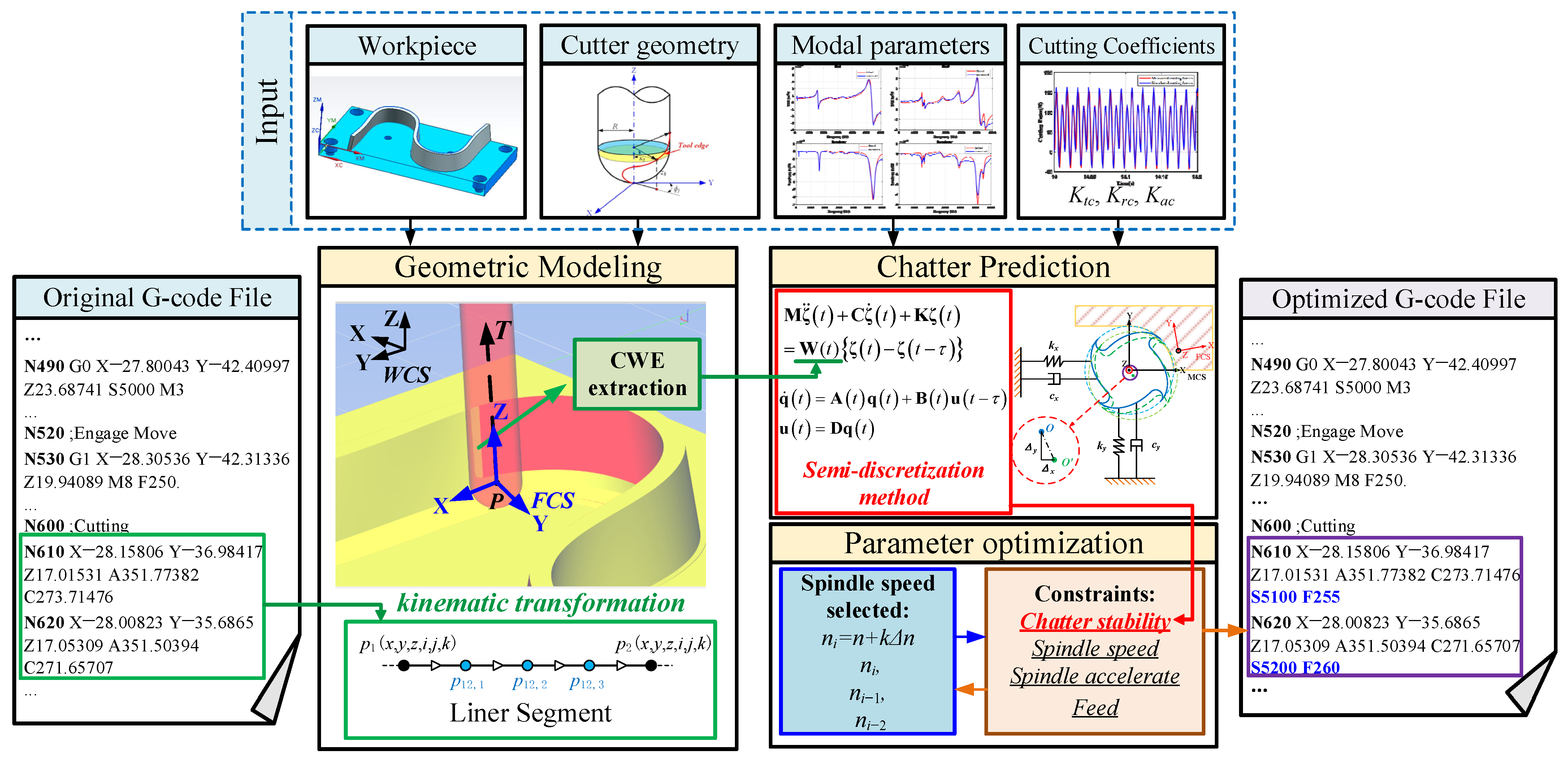
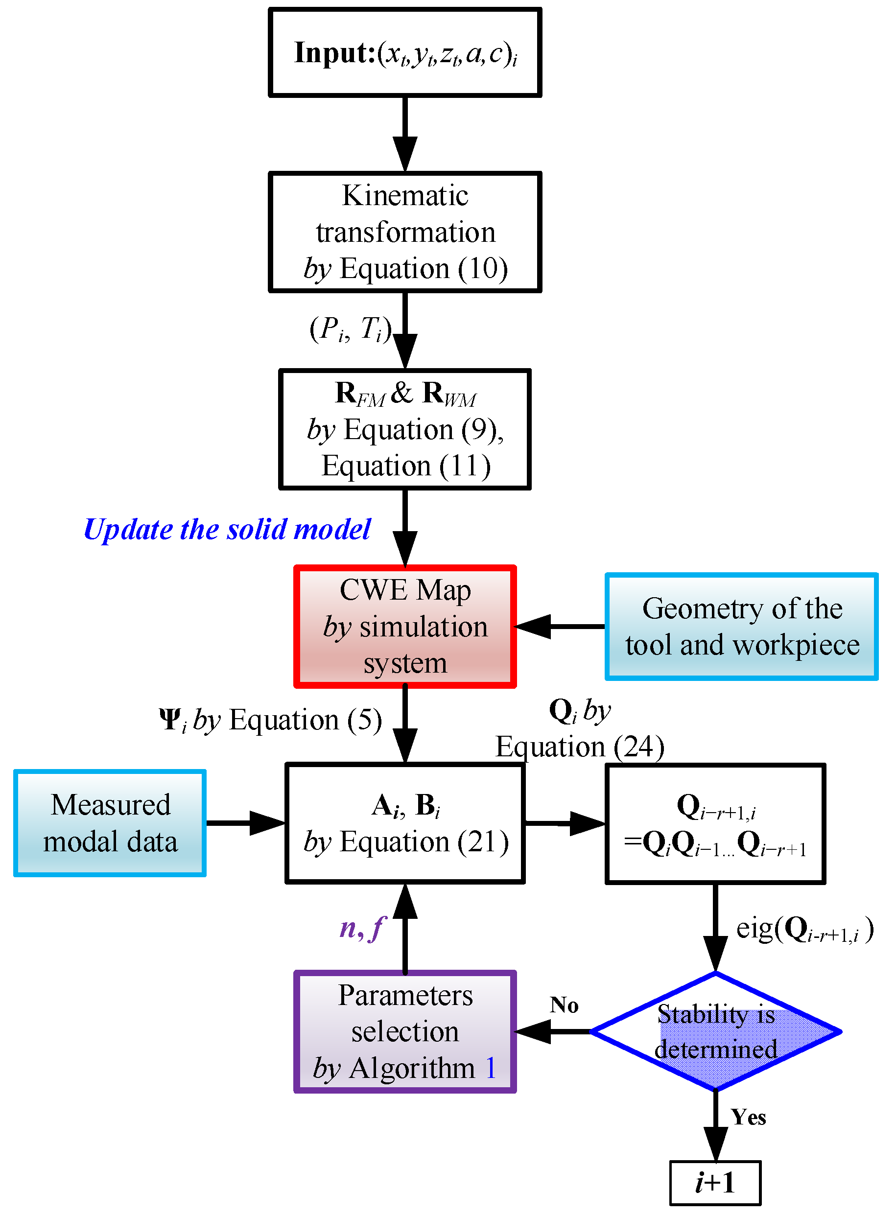
2. The Chatter-Free Parameter Optimization Approach in Five-Axis Milling

Figure 1 illustrates the procedure of the chatter-free parameter optimization approach. Above all, the G-code file, the workpiece model, and the cutter geometry information are loaded into the system for the geometric modeling. Based on the five-axis kinematic transformation, the tool point position (x, y, z) and the tool orientation (i, j, k) in the workpiece coordinate system (WCS) are calculated at the discrete location in the segment of the tool path. Furthermore, the tool swept volume is created based on the two adjacent tool positions. The CWE is extracted by the Boolean intersection operation between the current tool profile surface and the solid model of the workpiece. Then, the chatter stability prediction model for five-axis milling is built based on the CWE calculation, the coordinate transformation matrix, and the identified parameters (e.g., modal parameters and cutting coefficients). Therefore, the stability is predicted by applying the semi-discretization to solve the DDE. Next, chatter-free parameter optimization is carried out with the constraints of spindle speed, spindle acceleration, et al. If all the parameters satisfy the constraints, the optimized cutting parameters are rewritten in the G-code file. If a constraint is not met, the machining parameters are selected around the original set or recursively searched for optimization. Finally, the optimized G-code file is finished for the chatter-free five-axis machining.
Compared with the traditional SLD-based parameter selection method, the change of cutting condition is considered in this proposed approach, which makes it more accurate in five-axis milling. In addition, this chatter-free parameter optimization integrated with the virtual machining simulation has these three following advantages:
  • Offline simulation ensures sufficient calculation time;
  • Predicting optimization with constraints makes the machining process more operable and more reliable;
  • This rolling optimization strategy takes the machining condition along the whole tool path into consideration.

3. Dynamic Milling Force and Kinematic Transformation

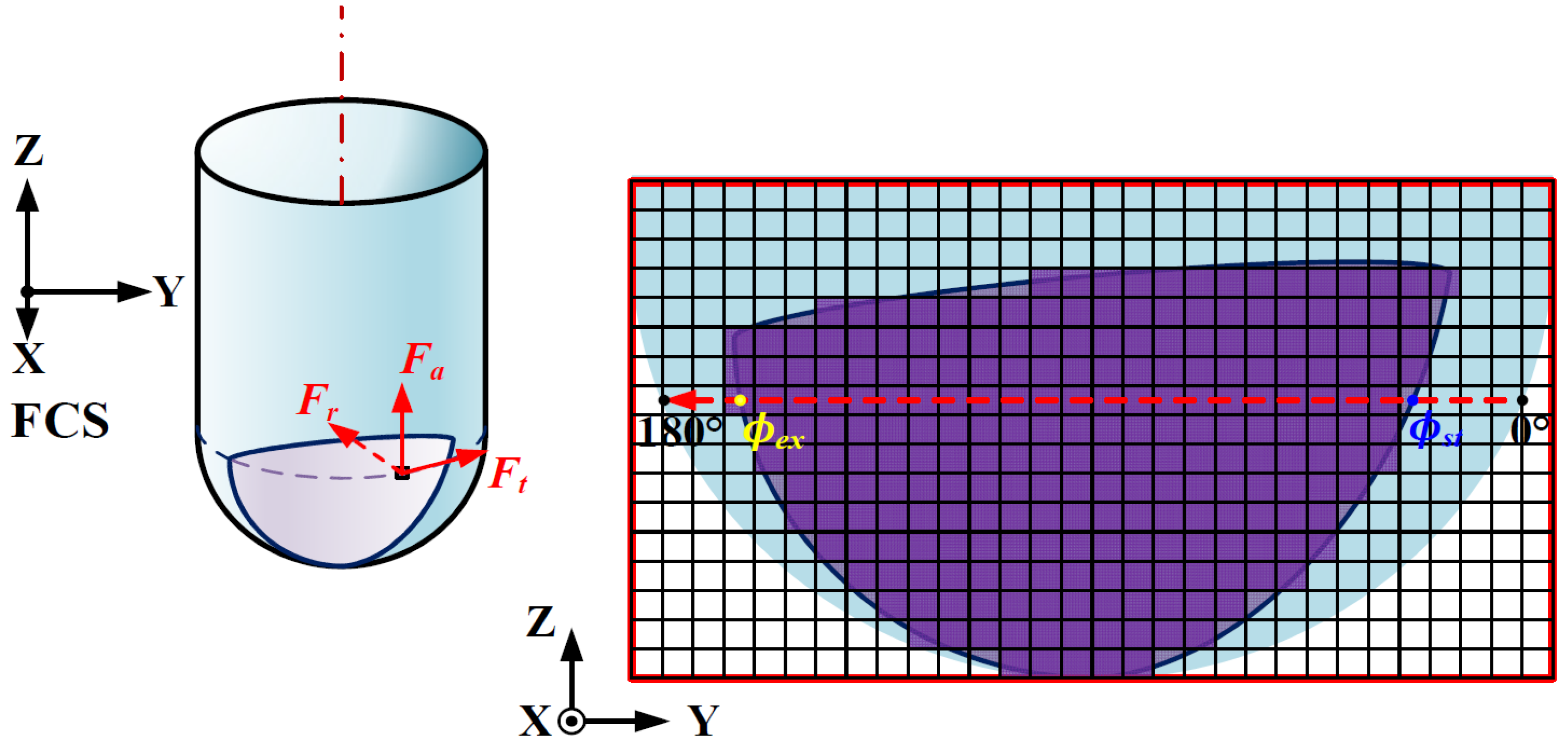
3.1. Dynamic Milling Force Model

In this section, the dynamic milling forces are calculated based on the instantaneous mechanistic force model [46]. The tangential differential force dFtjk, radial differential force dFrjk, and axial differential force dFajk acting on the kth cutting element of the jth tooth are represented as
d F t j k = K t c h ( ϕ j k ) d b + K t e d S d F r j k = K r c h ( ϕ j k ) d b + K r e d S d F a j k = K a c h ( ϕ j k ) d b + K a e d S
where ϕjk is the instantaneous immersion angle and h(ϕjk) is the undeformed chip thickness. Ktc, Krc, Kac, Kte, Kre, and Kae are the cutting force coefficients, db is chip width, and dS is the cutter segment length.
The expression for the chip thickness at height z of the jth flute is given by
h ( ϕ j k , z ) = ε ( ϕ j k ( z ) ) [ c X j ( z ) sin ( ϕ j k ( z ) θ s ( z ) ) sin ( κ ( z ) ) c Z j ( z ) cos ( κ ( z ) ) ]
where cXj and cZj are the feed per flute in the horizontal direction and the vertical direction, respectively. κ is the axial immersion angle and θs is the shift angle. ε(ϕjk(z)) is a criterion function to determine whether the tooth is in cut based on the entry (ϕst) and exit (ϕex) immersion angle pairs. Hence, if the cutting edge is engaged with the workpiece, ε equals 1, and else, ε equals 0.
The dynamic chip thickness is calculated from Equation (2), which can be expressed as
h d ( ϕ j k , z ) = ε [ sin ϕ j k ( z ) sin ( κ ( z ) ) cos ϕ j k ( z ) sin ( κ ( z ) ) cos ( κ ( z ) ) ] n ( ϕ j k ( z ) , z ) { Δ X ( t ) Δ Y ( t ) Δ Z ( t ) } F C S = ε ( ϕ j k ( z ) ) n ( ϕ j k ( z ) , z ) { Δ X ( t ) Δ Y ( t ) Δ Z ( t ) } F C S
where the displacement difference vector { Δ X ( t ) Δ Y ( t ) Δ Z ( t ) } F C S T is defined as the difference between the displacement { x ( t ) y ( t ) z ( t ) } F C S T at present and the displacement { x ( t τ ) y ( t τ ) z ( t τ ) } F C S T one tooth period before in the feed coordinate system (FCS). τ is the one tooth period and equals τ = 60/(Nn), where N is the num of flutes, and n is the spindle speed. Moreover, the following equation holds:
{ Δ X ( t ) Δ Y ( t ) Δ Z ( t ) } F C S = { x ( t ) y ( t ) z ( t ) } F C S { x ( t τ ) y ( t τ ) z ( t τ ) } F C S
By inserting Equation (3) to Equation (1), the dynamic cutting force can be derived as follows:
{ F x , d F y , d F z , d } F C S = j = 1 N k = 1 M ( H { K t c K r c K a c } ε ( ϕ j k ( z ) ) d b n ( ϕ j k ( z ) , z ) { Δ X ( t ) Δ Y ( t ) Δ Z ( t ) } F C S ) = j = 1 N k = 1 M ( H { K t c K r c K a c } ε ( ϕ j k ( z ) ) d b n ( ϕ j k ( z ) , z ) ) Ψ ( ϕ ) { Δ X ( t ) Δ Y ( t ) Δ Z ( t ) } F C S
where H is the transformation matrix and equals
H = [ cos ( ϕ j k ( z ) ) sin ( κ ( z ) ) sin ( ϕ j k ( z ) ) cos ( κ ( z ) ) sin ( ϕ j k ( z ) ) sin ( ϕ j k ( z ) ) sin ( κ ( z ) ) cos ( ϕ j k ( z ) ) cos ( κ ( z ) ) cos ( ϕ j k ( z ) ) 0 cos ( κ ( z ) ) sin ( κ ( z ) ) ]
Via the coordinate transformation, the cutting forces on the jth flute at height z are transformed from tangential, radial, and axial directions to the x-y-z directions in FCS.

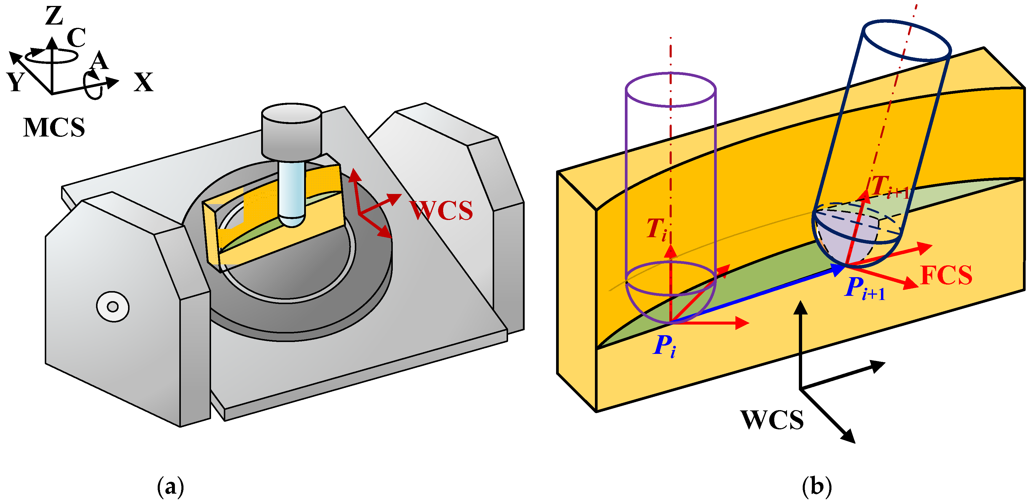
3.2. Transformations to the Machine Coordinate

For five-axis milling, the feed direction and tool orientation change along the tool path. The modal parameters of the spindle-cutter system are measured by impact testing. Hence, the transformation from FCS to machine coordinate system (MCS) is constructed for the stability analysis.
As shown in Figure 2, the cutting forces transform from FCS to WCS as
{ F x F y F z } W C S = R F W { F x F y F z } F C S
where RFW is the transformation matrix, and equals RFW = [{XT} {YT} {ZT}]. {XT}, {YT}, and {ZT} are the unite x-axis, y-axis, and z-axis direction vectors of FCS expressed in WCS, respectively, which can be calculated with the cutter location (CL) data [47]. {Pi} and {Ti} are the tool tip coordinate vector {x, y, z}wcs and tool orientation vector {i, j, k}wcs, respectively, at the ith tool path segment. The feed direction vector {FT} is given as
{ F T } = { P i + 1 } { P i } | { P i + 1 } { P i } |
The {XT}, {YT}, and {ZT} are calculated as
{ Z T } = { T i + 1 } | { T i + 1 } | ,   { Y T } = { T i + 1 } × { F T } | { T i + 1 } × { F T } | ,   { X T } = { Y T } × { Z T } | { Y T } × { Z T } |
CL data can be obtained from each axis position. In addition, for an AC-type five-axis machine, {Pi} = {x, y, z} and {Ti} = {i, j, k} are calculated with the positions (xt, yt, zt, at, ct) through the kinematic transformation:
{ x = x t cos ( c t ) y t cos ( a t ) sin ( c t ) + z t sin ( a t ) sin ( c t ) y = x t s i n ( c t ) + y t cos ( a t ) cos ( c t ) z t sin ( a t ) cos ( c t ) z = y t sin ( a t ) + z t cos ( a t ) i = sin ( a t ) sin ( c t ) j = sin ( a t ) cos ( c t ) k = cos ( a t )
Therefore, the rotational transfer matrix from WCS to MCS is formulated as follows:
R W M = R z ( c t ) R X ( a t ) = [ cos ( c t ) sin ( c t ) cos ( a t ) sin ( c t ) sin ( a t ) sin ( c t ) cos ( c t ) cos ( a t ) cos ( c t ) sin ( a t ) 0 sin ( a t ) cos ( a t ) ]
Hence, the dynamic cutting forces expressed in the MCS are as follows:
{ F x , d F y , d F z , d } M C S = R W M { F x , d F y , d F z , d } W C S
The dynamic displacement transforms from FCS to MCS, which is given as follows:
{ Δ X ( t ) Δ Y ( t ) Δ Z ( t ) } F C S = R F W 1 { Δ X ( t ) Δ Y ( t ) Δ Z ( t ) } W C S = R F W 1 R W M 1 { Δ X ( t ) Δ Y ( t ) Δ Z ( t ) } M C S
By substituting Equations (5), (7), and (13) into Equation (12), the dynamic cutting forces in the MCS are derived:
{ F x , d F y , d F z , d } M C S = R W M R F W { F x , d F y , d F z , d } F C S = R F M Ψ ( ϕ ) R F M 1 { Δ X ( t ) Δ Y ( t ) Δ Z ( t ) } M C S
where RFM is the matrix for the transformation from FCS to MCS and equals R F W = R W M R F W .

4. Chatter Stability Prediction for Five-Axis Milling

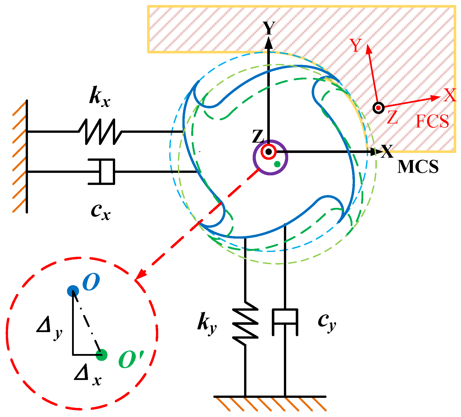
4.1. Chatter Stability Prediction Model

While the stiffness of the spindle-cutter system in the z-direction is assumed to be rigid, the dynamic milling system is simplified as a basic two-degrees-of-freedom system in the MCS, as shown in Figure 3. The dynamic equations can be expressed as:
[ m x 0 0 m y ] [ x ¨ ( t ) y ¨ ( t ) ] + [ c x 0 0 c y ] [ x ˙ ( t ) y ˙ ( t ) ] + [ k x 0 0 k y ] [ x ( t ) y ( t ) ] = [ F x , d ( t ) F y , d ( t ) ]
By substituting Equation (14) into Equation (15), Equation (15) can be rewritten as follows:
M ζ ¨ ( t ) + C ζ ˙ ( t ) + K ζ ( t ) = W ( t ) { ζ ( t ) ζ ( t τ ) }
where M, C, and K denote the system mass, damping, and stiffness matrices, respectively. ζ(t) represents the displacement vector in the x- and y-directions of MCS and equals { x ( t ) y ( t ) } M C S T . W(t) is the cutting force coefficient submatrix derived from Equation (14), which consists of the elements in the first two columns and the first two rows of R F M Ψ ( t ) R F M 1 :
R F M Ψ ( t ) R F M 1 = [ a 11 a 12 a 13 a 21 a 22 a 23 a 31 a 32 a 33 ] W ( t ) = [ a 11 a 12 a 21 a 22 ]
Equation (16) can be rewritten as the space state equation in the time domain:
q ˙ ( t ) = A ( t ) q ( t ) + B ( t ) u ( t τ ) u ( t ) = D q ( t )
where
q ( t ) = ( ζ ( t ) ζ ˙ ( t ) )
A ( t ) = ( 0 I ( M 1 ( K W ( t ) ) ) M 1 C ) B ( t ) = ( 0 M 1 W ( t ) ) D = ( I 0 )
I is the identity matrix (with 2 × 2 dimensions). Based on the semi-discretization method [48], the DDE Equation (18) is approximated based on a sequence of the ordinary differential equation (ODE) with discrete time intervals. Let hT be the sampling period of the path segment, so that τ = phT, and p = int ( τ h T + 1 2 ) . In the ith discrete interval [ti, ti+1], the semi-discrete system of Equation (18) is described as
q i + 1 = e A i h T q i + 1 2 ( e A i h T I ) A i 1 B i ( q i p + q i p + 1 )
Equations (21) and (18) can be rewritten as the discrete map form:
z i + 1 = Q i z i
where zi and zi+1 represent the augmented state vectors in the ith and (i + 1)th discrete interval:
z i = ( q i u i 1 u i p ) T = ( ζ i ζ ˙ i ζ i 1 ζ i 2 ζ i p ) T
Moreover, Qi denotes the transition matrix, which can be derived as
Q i = ( e A i h T 0 0 1 2 ( e A i h T I ) A i 1 B i 1 2 ( e A i h T I ) A i 1 B i D 0 0 0 0 0 I 0 0 0 0 0 0 I 0 )
Thus, the transition equation of the states is given by coupling the coefficient matrices in each interval within a simulation period τ:
z r = Q r Q 2 Q 1 z 0 = Q z 0
Based on the Floquet theory, the eigenvalues of the transition matrix Q are used to judge the stability of the system. If all modulus of the eigenvalues of Q(t) are less than one, the system is asymptotically stable.

4.2. Multi-Frequency Analysis for Chatter Stability

In Equation (15), the dynamic milling system is simplified as two single-degrees-of-freedom (SDOF) systems in the x- and y-directions. However, the machine tool has multiple degrees of freedom (MDOF) in different directions. The transfer function in each direction can be expressed as the accumulation of second-order differential equations in the Laplace domain:
h ( s ) = k = 1 n [ α k + β k s s 2 + 2 ξ k ω n , k s + ω n , k 2 ] m o d e k
where αk and βk are the real parts and the imaginary parts of the numerator in kth mode, respectively. Considering the real mode shape, the imaginary part of the numerator is negligible (βk = 0). The transfer function is given as
X ( s ) F ( s ) = k = 1 n u k 2 1 m k s 2 + c k s + k k
where uk is the gain of the real mode shape. The dynamic displacements in each direction are decomposed into the modal displacement components. Therefore, the dynamic equations (Equation (15)) are modified as
M q x ¨ q + C q x ˙ q + K q x q = u q F q , d   ( q = x ,   y )
where the subscript q represents the different directions, and Mq, Cq, and Kq are the mass, damping, and stiffness matrices, respectively. uq is the vector of mode shape:
u q = [ u q , 1 2 u q , k 2 ]
Equation (16) can be rewritten as follows for MDOF:
Where M t = [ M x M y ] , C t = [ C x C y ] , K t = [ K x K y ] , E = [ 1 1 k x 1 1 k y ] , U = [ u 2 x , 1 u 2 x , k x u 2 y , 1 u 2 y , k y ] T , ζ t ( t ) = [ x t , 1 x t , k x y t , 1 y t , k y ] T .
Hence, the solution of Equation (28) for MDOF is the same as Equation (16) for SDOF with W ( t ) = U R F M Ψ ( t ) R F M 1 E .

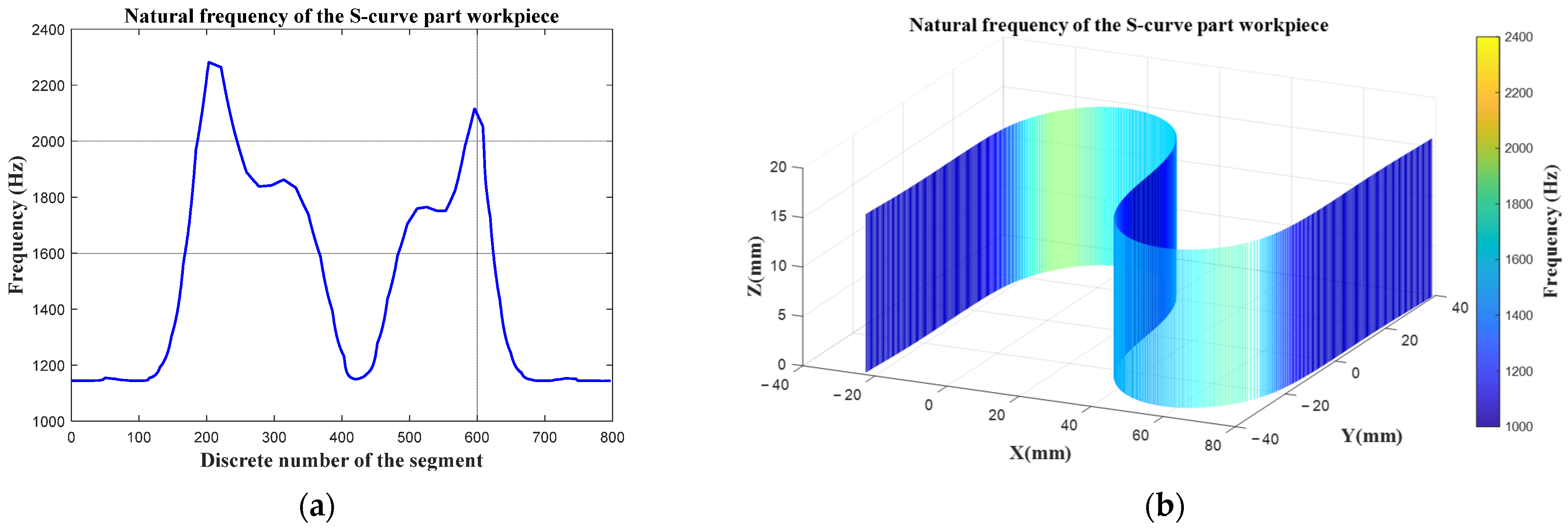
4.3. The Coupling Effect of the Workpiece Stiffness

For weak stiffness workpiece machining, the vibration of the workpiece should be taken into consideration. The dynamic equations of the coupling system are established as follows:
M w ζ ¨ w ( t ) + C w ζ ˙ w ( t ) + K w ζ w ( t ) = F d , F C S M t ζ ¨ t ( t ) + C t ζ ˙ t ( t ) + K t ζ t ( t ) = F d , M C S Δ F C S = Δ w , F C S + Δ t , F C S
where Mw, Cw, and Kw denote the mass, damping, and stiffness matrices for the workpiece, respectively. ζt(t) is the model displacement. Hence, the modification of Equation (29) is presented as
M ζ ¨ ( t ) + C ζ ˙ ( t ) + K ζ ( t ) = [ U R F M I ] Ψ ( ϕ ( t ) ) [ R F M 1 E I ] { ζ ( t ) ζ ( t T ) }
where M = [ Μ t Μ w ] , C = [ C t C w ] , K = [ K t K w ] , ζ ( t ) = [ x t , 1 x t , k x y t , 1 y t , k y z t x w y w z w ] T .
Considering the stiffness of the spindle-cutter system in the z-direction and the stiffness of the workpiece in the feed and axial direction are rigid, the system is simplified as follows:
[ U R F M I ] Ψ ( t ) [ R F M 1 E I ] = [ a 11 a 12 a 16 a 21 a 22 a 26 a 61 a 62 a 66 ] W ( t ) = [ a 11 a 12 a 16 a 21 a 22 a 26 a 51 a 52 a 56 ]
where ζ ( t ) = [ x t , 1 x t , k x y t , 1 y t , k y y w ] T .
In this study, an S-curve thin-walled part five-axis milling is carried out as the machining experiment. The operation of the hammer impact test in the particular position (e.g., the center of the S-curve and the inner corner point) of the workpiece is inconvenient. For the workpiece model analysis, the contact constraint can be regarded as rigidity so that the theoretical calculation has good accuracy. Therefore, the S-curve thin-walled specimen is modeled as a cantilever beam for modal analysis. According to classical bending theory, the natural frequency ωj and modal shape ψj are present:
ω j = ( E I ρ A L 4 ) 1 / 2 a j 2
ψ ( x ) = C 1 { [ sin ( α j x L ) sinh ( α j x L ) ] sin ( α j ) + sinh ( α j ) cos ( α j ) + cosh ( α j ) [ cos ( α j x L ) cosh ( α j x L ) ] }
where L is the length of the beam, A is the sectional area, E is the Young modulus, ρ is the density, I is the inertia, x is the position along the beam, and αj is the root of the cantilever bending characteristic equation:
cos ( α ) cosh ( α ) + 1 = 0
The S-curve is segmented into rectangular sections and loop sections. For the rectangular section, the inertia Ixr equals
I x y = 1 12 w h 3
where w and h are the rectangular section’s width and height, respectively. For the loop section, the inertia Ixl equals
I x l = 1 8 ( R 4 r 4 ) θ + 1 2 ( R + r 2 ) 2 θ + 1 8 ( R 4 r 4 ) sin θ 4 3 ( R + r 2 ) ( R 3 r 3 ) sin θ 2
where r and R are radiuses of the inner and outer circle, respectively, and θ is the intersection angle of the loop. Hence, the natural frequency of the S-curve part workpiece at the discrete location can be calculated by Equation (33), as presented in Figure 4.
However, the accuracy of the proposed chatter prediction method can be increased by building a more accurate workpiece model through the finite element method, especially for the thin-walled workpiece with the sculptured surface [49].

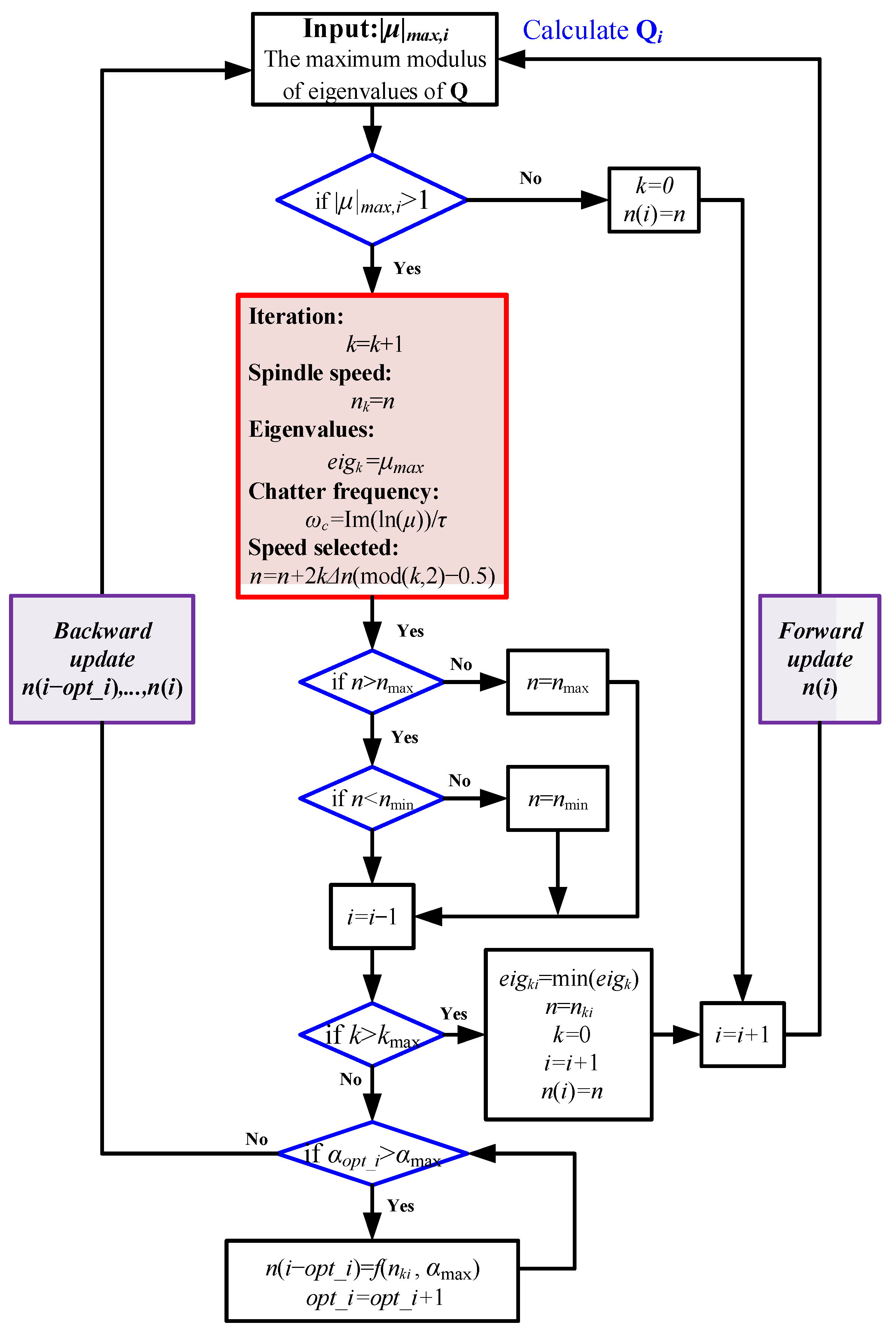
5. Parameter Optimization for Chatter Stability

For the five-axis milling process, the geometric condition constantly changes along the tool path with the variation of the feed direction and the tool orientation, as shown in Figure 2 and Figure 5. The engagement angles (ϕst, ϕex) are identified by the CWE, which is obtained using the machining simulation system developed by the author’s laboratory. Based on the solid modeling method [50,51], the CWE map is extracted through the intersection Boolean operation between the solid model of the tool and the workpiece at each discrete interval. As shown in Figure 5, the envelope of the tool model and the contact patch between the workpiece and the tool are projected to the y-z plane in FCS. In addition, the engagement angles are calculated at each discrete height along the tool orientation.
Because
l p a t h = h f   p = 60 n N h = 60 l p a t h f N n
where lpath is the length of the path segment, if p and lpath remain constant, the feed rate f varies in direct proportion to the spindle speed n.
Therefore, when unstable conditions are predicted, the stable speed is searched around the current spindle speed n for optimization. By the stability prediction of five-axis milling, the simulation procedure and the parameters selection algorithm are given in Figure 6 and Figure 7, where nmax and nmin are the maximum and minimum spindle speed constraints to ensure the machine works under stable machining conditions. ωc is the chatter frequency, which can be calculated by Equation (39):
ω c = Im ( ln ( μ ) ) / τ
Δn is the speed step size in each iteration, αmax is the maximum spindle acceleration, opti_i is the iteration count in the inner loop considering the acceleration and deceleration of the spindle speed limit, and αopt_i is the calculated spindle acceleration according to the optimized speed. If the spindle acceleration is over the limit of acceleration constraints, the spindle speed in the previous segment should be modified as follows:
n ( i o p t i _ i ) = 1 2 n k i 2 2 α max n i o p t i _ i ( t i o p t i _ i t i o p t i _ i 1 ) + 1 2 n k i
The spindle speed is rollback-optimized, and the transition matrix Qi is calculated accordingly. In addition, kmax is the maximum iteration. If the system has exceeded the maximum stability threshold, the search for optimum stable spindle speed can terminate by introducing kmax.

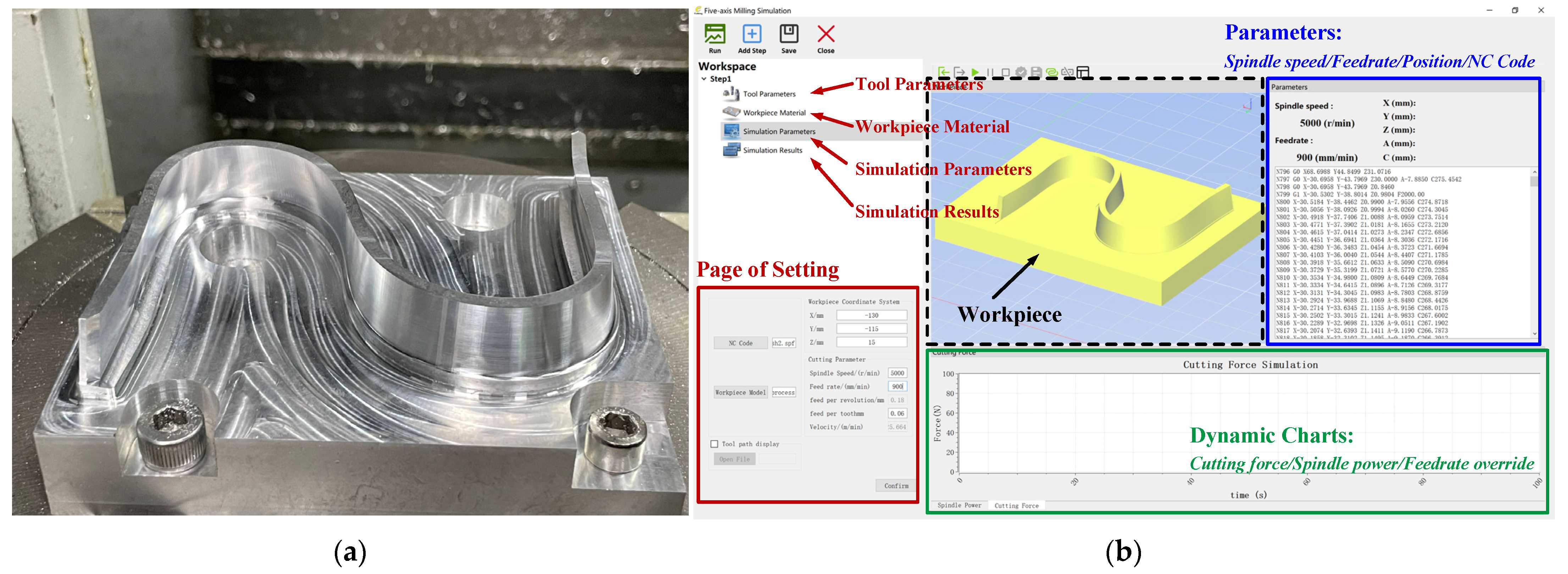
6. Simulation and Experimental Verification

The S-curve machining test, as an international standard, is usually used to verify the five-axis machining performance [52]. As shown in Figure 8, an S-curve part with sculptured surfaces is finishing-machined to verify the effectiveness of the proposed chatter prediction model and parameter optimization method. A five-axis machine tool XH7132A and a two-fluted, 8 mm diameter ball-end mill with a 30-degree helix is used for the five-axis machining test. The frequency response functions (FRFs) of the spindle-cutter system are measured by applying the hammering tests to the ball-end mill in the x- and y-directions of the MCS. The identified modal parameters from the measured and modified FRFs (Figure 9) are presented in Table 1. The cutting force coefficients of the workpiece material Aluminum 7075, as presented in Table 2, are identified from the cutting force test using a table dynamometer Kistler 9257B. The parameters of the workpiece material and cross-section are presented in Table 3. The simulation parameters for optimization are presented in Table 4. The finish machining of this S-curve part has a 1 mm allowance in the normal direction of the surface. The engagement geometry and radius of the loop cross-section are identified by a self-developed machining simulation system, as shown in Figure 10. This machining simulation software is developed based on the C++ programming language with the development platform of Visual Studio 2019 and the open architecture of Qt. Meanwhile, the three-dimensional engine AnyCAD is used for geometric modeling and scene rendering. This virtual machining system has been used for the digital twin building with the function of material removal processing simulation, dynamic cutting force simulation, and contour error analysis [53].
Before the optimization, the spindle speed is constant at 5000 r/min, and the feed velocity is constant at 900 mm/min. The positions of each axis are presented in Figure 11. The CWE at the different discrete locations is shown in Figure 12 and Figure 13(a)–(f) to illustrate the chip section evolution.
The chatter prediction result is shown in Figure 14, with the maximum eigenvalues of the transition matrix at each tool position along the tool path. As discussed in Section 3.1, the eigenvalue should be less than one for a stable dynamic system. As shown in Figure 14b, the tool locations with eigenvalues greater than one are marked in red. Based on the optimization algorithm proposed in Section 4, the spindle speed is optimized, as shown in Figure 15. The chatter prediction result for the optimized spindle speed is shown in Figure 16. It can be found that all eigenvalues in each position are less than one.
The cutting test results before and after the parameter optimization are shown in Figure 17 and Figure 18. By comparison of the surface quality and the sound spectrum, the cutting chatter is detected at the beginning and the end of the S-curve, which is caused by the weak stiffness of the workpiece, as presented in Figure 4. For stable machining, the major frequency should be the multiplier of the tooth passing frequency. Conversely, the chatter frequency will stick out in the frequency components when the chatter occurs. From the frequency analysis results presented in Figure 18, the dominant frequency of 728 Hz is closer to the chatter frequency (731 Hz) calculated by Equation (39) in the milling process. Meanwhile, this chatter frequency is from the coupling effect of the workpiece and the tool, considering the frequency of 728 Hz is not clear to the natural frequency of the workpiece or the tool either. After the optimization, the cutting process is stable, and the major frequencies of the sound spectrum are concentrated on the tooth passing frequency (200 Hz) multiplication. As shown in Figure 14b, the chatter phenomenon gets suppressed with the stiffness of the workpiece enhanced along the tool path. Besides, it can be observed that chatter marks occur in the inner corner of the S-curve, as shown in Figure 17. The main reason is the increase of the cutting engagement geometry (Figure 13e), which is in agreement with the prediction in Figure 14. When the spindle speed is optimized by the method presented in Figure 7, the chatter is eliminated, and the surface finish becomes smooth.

7. Conclusions

This study proposed a parameters optimization method for chatter stability in the five-axis milling process. The chatter stability of the dynamic milling system is modeled at each segment location along the tool path. A multi-frequency solution for the chatter stability with a semi-discretization method is derived. Both the kinematic transformation and the variation of cutter-workpiece engagement geometry are considered in the chatter mechanism analysis. In addition, the workpiece structure is simplified as the cantilever beam for the modal analysis. The dynamic coupling effect of the workpiece and the tool is also discussed in Section 4.3. Moreover, chatter is avoided by parameter optimization based on stability prediction with the constraints of spindle speed and spindle acceleration. Finally, the finish machining of an S-curve part is carried out as the experimental cutting test. The comparisons of simulation and experimental results show that the proposed optimization algorithm can effectively stabilize processing and improve surface quality.

Author Contributions

X.T.: Theoretical analysis, algorithm research, and software development; Q.L.: Conceptualization and guidance of the research; L.W.: Writing review and edit; P.S.: Machining experiment. All authors have read and agreed to the published version of the manuscript.

Funding

This research received no external funding.

Data Availability Statement

Not applicable.

Conflicts of Interest

The authors declare no conflict of interest.

References

  1. Zhu, L.; Liu, C. Recent progress of chatter prediction, detection and suppression in milling. Mech. Syst. Signal Process. 2020, 143, 106840. [Google Scholar] [CrossRef]
  2. Altintaş, Y.; Budak, E. Analytical Prediction of Stability Lobes in Milling. CIRP Ann. 1995, 44, 357–362. [Google Scholar] [CrossRef]
  3. Altintas, Y.; Weck, M. Chatter Stability of Metal Cutting and Grinding. CIRP Ann. 2004, 53, 619–642. [Google Scholar] [CrossRef]
  4. Kardes, N.; Altintas, Y. Mechanics and Dynamics of the Circular Milling Process. J. Manuf. Sci. Eng. 2006, 129, 21–31. [Google Scholar] [CrossRef]
  5. Merdol, S.D.; Altintas, Y. Multi Frequency Solution of Chatter Stability for Low Immersion Milling. J. Manuf. Sci. Eng. 2004, 126, 459–466. [Google Scholar] [CrossRef]
  6. Ozturk, E.; Budak, E. Dynamics and Stability of Five-Axis Ball-End Milling. J. Manuf. Sci. Eng. 2010, 132, 021003. [Google Scholar] [CrossRef]
  7. Bayly, P.V.; Mann, B.P.; Schmitz, T.L.; Peters, D.A.; Stepan, G.; Insperger, T. Effects of Radial Immersion and Cutting Direction on Chatter Instability in End-Milling. In Proceedings of the ASME 2002 International Mechanical Engineering Congress and Exposition, New Orleans, LA, USA, 17–22 November 2002; pp. 351–363. [Google Scholar]
  8. Bayly, P.V.; Halley, J.E.; Mann, B.P.; Davies, M.A. Stability of Interrupted Cutting by Temporal Finite Element Analysis. J. Manuf. Sci. Eng. 2003, 125, 220–225. [Google Scholar] [CrossRef]
  9. Insperger, T.; Stépán, G.; Bayly, P.V.; Mann, B.P. Multiple chatter frequencies in milling processes. J. Sound Vib. 2003, 262, 333–345. [Google Scholar] [CrossRef]
  10. Insperger, T.; Mann, B.P.; Stépán, G.; Bayly, P.V. Stability of up-milling and down-milling, part 1: Alternative analytical methods. Int. J. Mach. Tools Manuf. 2003, 43, 25–34. [Google Scholar] [CrossRef] [Green Version]
  11. Seguy, S.; Insperger, T.; Arnaud, L.; Dessein, G.; Peigné, G. On the stability of high-speed milling with spindle speed variation. Int. J. Adv. Manuf. Technol. 2010, 48, 883–895. [Google Scholar] [CrossRef]
  12. Dong, X.; Zhang, W. Chatter suppression analysis in milling process with variable spindle speed based on the reconstructed semi-discretization method. Int. J. Adv. Manuf. Technol. 2019, 105, 2021–2037. [Google Scholar] [CrossRef]
  13. Gao, J.; Altintas, Y. Chatter stability of synchronized elliptical vibration assisted milling. CIRP J. Manuf. Sci. Technol. 2020, 28, 76–86. [Google Scholar] [CrossRef]
  14. Ding, Y.; Zhu, L.; Zhang, X.; Ding, H. A full-discretization method for prediction of milling stability. Int. J. Mach. Tools Manuf. 2010, 50, 502–509. [Google Scholar] [CrossRef]
  15. Zhang, X.; Xiong, C.; Ding, Y.; Ding, H. Prediction of chatter stability in high speed milling using the numerical differentiation method. Int. J. Adv. Manuf. Technol. 2017, 89, 2535–2544. [Google Scholar] [CrossRef]
  16. Pour, M.; Torabizadeh, M.A. Improved prediction of stability lobes in milling process using time series analysis. J. Intell. Manuf. 2016, 27, 665–677. [Google Scholar] [CrossRef]
  17. Comak, A.; Budak, E. Modeling dynamics and stability of variable pitch and helix milling tools for development of a design method to maximize chatter stability. Precis. Eng. 2017, 47, 459–468. [Google Scholar] [CrossRef]
  18. Ozkirimli, O.; Tunc, L.T.; Budak, E. Generalized model for dynamics and stability of multi-axis milling with complex tool geometries. J. Mater. Process. Technol. 2016, 238, 446–458. [Google Scholar] [CrossRef]
  19. Guo, M.; Wei, Z.; Wang, M.; Li, S.; Wang, J.; Liu, S. Modal parameter identification of general cutter based on milling stability theory. J. Intell. Manuf. 2021, 32, 221–235. [Google Scholar] [CrossRef]
  20. Li, W.; Wang, L.; Yu, G. Chatter prediction in flank milling of thin-walled parts considering force-induced deformation. Mech. Syst. Signal Process. 2022, 165, 108314. [Google Scholar] [CrossRef]
  21. Sun, Y.; Jiang, S. Predictive modeling of chatter stability considering force-induced deformation effect in milling thin-walled parts. Int. J. Mach. Tools Manuf. 2018, 135, 38–52. [Google Scholar] [CrossRef]
  22. Eto, J.; Hayasaka, T.; Shamoto, E. Proposal of novel chatter-free milling strategy utilizing extraordinarily numerous flute endmill and high-speed high-power machine tool. Precis. Eng. 2023, 80, 95–103. [Google Scholar] [CrossRef]
  23. Pelayo, G.U. Modelling of static and dynamic milling forces in inclined operations with circle-segment end mills. Precis. Eng. 2019, 56, 123–135. [Google Scholar] [CrossRef]
  24. Sun, C.; Altintas, Y. Chatter free tool orientations in 5-axis ball-end milling. Int. J. Mach. Tools Manuf. 2016, 106, 89–97. [Google Scholar] [CrossRef]
  25. Ma, J.; Zhang, D.; Liu, Y.; Wu, B.; Luo, M. Tool posture dependent chatter suppression in five-axis milling of thin-walled workpiece with ball-end cutter. Int. J. Adv. Manuf. Technol. 2017, 91, 287–299. [Google Scholar] [CrossRef]
  26. Lu, Y.; Ding, Y.; Zhu, L. Dynamics and Stability Prediction of Five-Axis Flat-End Milling. J. Manuf. Sci. Eng. 2017, 139, 061015. [Google Scholar] [CrossRef]
  27. Dai, Y.; Li, H.; Wei, Z.; Zhang, H. Chatter stability prediction for five-axis ball end milling with precise integration method. J. Manuf. Process. 2018, 32, 20–31. [Google Scholar] [CrossRef]
  28. Li, J.; Kilic, Z.M.; Altintas, Y. General Cutting Dynamics Model for Five-Axis Ball-End Milling Operations. J. Manuf. Sci. Eng. 2020, 142, 121003. [Google Scholar] [CrossRef]
  29. Zhan, D.; Jiang, S.; Niu, J.; Sun, Y. Dynamics modeling and stability analysis of five-axis ball-end milling system with variable pitch tools. Int. J. Mech. Sci. 2020, 182, 105774. [Google Scholar] [CrossRef]
  30. Zhan, D.; Li, S.; Jiang, S.; Sun, Y. Optimal pitch angles determination of ball-end cutter for improving five-axis milling stability. J. Manuf. Process. 2022, 84, 832–846. [Google Scholar] [CrossRef]
  31. Budak, E.; Tekeli, A. Maximizing Chatter Free Material Removal Rate in Milling through Optimal Selection of Axial and Radial Depth of Cut Pairs. CIRP Ann. 2005, 54, 353–356. [Google Scholar] [CrossRef]
  32. Merdol, S.D.; Altintas, Y. Virtual cutting and optimization of three-axis milling processes. Int. J. Mach. Tools Manuf. 2008, 48, 1063–1071. [Google Scholar] [CrossRef]
  33. Wu, P.; He, Y.; Li, Y.; He, J.; Liu, X.; Wang, Y. Multi-objective optimisation of machining process parameters using deep learning-based data-driven genetic algorithm and TOPSIS. J. Manuf. Syst. 2022, 64, 40–52. [Google Scholar] [CrossRef]
  34. Zhang, X.; Ding, H. Note on a novel method for machining parameters optimization in a chatter-free milling process. Int. J. Mach. Tools Manuf. 2013, 72, 11–15. [Google Scholar] [CrossRef]
  35. Ringgaard, K.; Mohammadi, Y.; Merrild, C.; Balling, O.; Ahmadi, K. Optimization of material removal rate in milling of thin-walled structures using penalty cost function. Int. J. Mach. Tools Manuf. 2019, 145, 103430. [Google Scholar] [CrossRef]
  36. Zhang, Y.; Xu, R.; Li, X.; Cheng, X.; Zheng, G.; Meng, J. A tool path generation method based on smooth machine rotary angle and tilt angle in five-axis surface machining with torus cutters. Int. J. Adv. Manuf. Technol. 2020, 107, 4261–4271. [Google Scholar] [CrossRef]
  37. An, S.; Cheng, Y.; Liu, X.; Li, M.; Shi, L. Research on Cutter Location Optimization of Tapered Ball End Mill Finish Flank Milling Ruled Surface Blade. Key Eng. Mater. 2013, 589–590, 421–426. [Google Scholar] [CrossRef]
  38. Sun, S.; Sun, Y.; Xu, J.; Lee, Y.-S. Iso-Planar Feed Vector-Fields-Based Streamline Tool Path Generation for Five-Axis Compound Surface Machining with Torus-End Cutters. J. Manuf. Sci. Eng. 2018, 140, 071013. [Google Scholar] [CrossRef] [Green Version]
  39. Meng, F.-J.; Chen, Z.-T.; Xu, R.-F.; Li, X. Optimal barrel cutter selection for the CNC machining of blisk. Comput. Aided Des. 2014, 53, 36–45. [Google Scholar] [CrossRef]
  40. Venkata Rao, K.; Murthy, P.B.G.S.N. Modeling and optimization of tool vibration and surface roughness in boring of steel using RSM, ANN and SVM. J. Intell. Manuf. 2018, 29, 1533–1543. [Google Scholar] [CrossRef]
  41. Unver, H.O.; Sener, B. A novel transfer learning framework for chatter detection using convolutional neural networks. J. Intell. Manuf. 2021, 1–20. [Google Scholar] [CrossRef]
  42. Mishra, R.; Singh, B. An ensemble approach to maximize metal removal rate for chatter free milling. J. Comput. Sci. 2022, 59, 101567. [Google Scholar] [CrossRef]
  43. Li, G.; Du, S.; Huang, D.; Zhao, C.; Deng, Y. Dynamics Modeling-Based Optimization of Process Parameters in Face Milling of Workpieces with Discontinuous Surfaces. J. Manuf. Sci. Eng. 2019, 141, 101009. [Google Scholar] [CrossRef]
  44. Mokhtari, A.; Jalili, M.M.; Mazidi, A. Optimization of different parameters related to milling tools to maximize the allowable cutting depth for chatter-free machining. Proc. Inst. Mech. Eng. Part B J. Eng. Manuf. 2021, 235, 230–241. [Google Scholar] [CrossRef]
  45. Wang, C.; Zhang, X.; Yan, R.; Chen, X.; Cao, H. Multi harmonic spindle speed variation for milling chatter suppression and parameters optimization. Precis. Eng. 2019, 55, 268–274. [Google Scholar] [CrossRef]
  46. Altintas, Y. Manufacturing Automation: Metal Cutting Mechanics, Machine Tool Vibrations, and CNC Design; Cambridge University Press: Cambridge, UK, 2012. [Google Scholar]
  47. Ferry, W.B.; Altintas, Y. Virtual Five-Axis Flank Milling of Jet Engine Impellers—Part I: Mechanics of Five-Axis Flank Milling. J. Manuf. Sci. Eng. 2008, 130, 011005. [Google Scholar] [CrossRef]
  48. Insperger, T.; Stépán, G. Semi-discretization. In Semi-Discretization for Time-Delay Systems: Stability and Engineering Applications; Springer New York: New York, NY, USA, 2011; pp. 39–71. [Google Scholar]
  49. Yang, Y.; Zhang, W.-H.; Ma, Y.-C.; Wan, M.; Dang, X.-B. An efficient decomposition-condensation method for chatter prediction in milling large-scale thin-walled structures. Mech. Syst. Signal Process. 2019, 121, 58–76. [Google Scholar] [CrossRef]
  50. Altintas, Y.; Kersting, P.; Biermann, D.; Budak, E.; Denkena, B.; Lazoglu, I. Virtual process systems for part machining operations. CIRP Ann. 2014, 63, 585–605. [Google Scholar] [CrossRef]
  51. Si, H.; Wang, L.; Zhang, J.; Liu, Z. A solid-discrete-based method for extracting the cutter-workpiece engagement in five-axis flank milling. Int. J. Adv. Manuf. Technol. 2018, 94, 3641–3653. [Google Scholar] [CrossRef]
  52. Pi, S.; Liu, Q.; Liu, Q. A novel dynamic contour error estimation and control in high-speed CNC. Int. J. Adv. Manuf. Technol. 2018, 96, 547–560. [Google Scholar] [CrossRef]
  53. Tong, X.; Liu, Q.; Pi, S.; Xiao, Y. Real-time machining data application and service based on IMT digital twin. J. Intell. Manuf. 2020, 31, 1113–1132. [Google Scholar] [CrossRef]
Figure 1. The procedure of the chatter-free parameter optimization approach.
Machines 11 00079 g001
Figure 2. Coordinate transformation for five-axis machining with an AC-type machine. (a) MCS and WCS; (b) WCS and FCS.
Machines 11 00079 g002
Figure 3. Simplified model of the dynamic milling system.
Machines 11 00079 g003
Figure 4. The natural frequency of the S-curve part workpiece. (a) Simulation result with the discrete number of the segment; (b) simulation result in three-dimensional space.
Machines 11 00079 g004
Figure 5. CWE map in five-axis milling.
Machines 11 00079 g005
Figure 6. The simulation procedure for five-axis milling.
Machines 11 00079 g006
Figure 7. Milling parameters selection algorithm.
Machines 11 00079 g007
Figure 8. S-curve machining: (a) S-curve workpiece; (b) machining simulation system.
Machines 11 00079 g008
Figure 9. Measured and fitted FRF in x- and y-directions: (a) Real part of FRF results in the x-direction; (b) Real part of FRF results in the y-direction; (c) Imaginary part of FRF results in the x-direction; (d) Imaginary part of FRF results in the y-direction.
Machines 11 00079 g009aMachines 11 00079 g009b
Figure 10. S-curve machining simulation.
Machines 11 00079 g010
Figure 11. Kinematic analysis of the tool tip and each feed axis.
Machines 11 00079 g011
Figure 12. Discrete tool point and tool orientation along the tool path. (a) Position: (−159.611, −120.131, 16.4135), Orientation: (0.1952, −0.1178, 0.9737); (b) Position: (−152.399, −85.5129, 16.0719), Orientation: (0.0332, −0.1933, 0.9806); (c) Position: (−117.322, −77.9995, 16.2067), Orientation: (−0.0652, −0.1544, 0.9859); (d) Position: (−96.158, 106.835, 15.38257), Orientation: (−0.0506, −0.020, 0.9985); (e) Position: (−75.3500, −142.4810, 13.7347), Orientation: (0.0413, 0.1725, 0.9841); (f) Position: (−58.4774, −107.6970, 13.5037), Orientation: (−0.273, 0.1101, 0.9721).
Machines 11 00079 g012
Figure 13. The CWEs at the noted positions of Figure 11.
Machines 11 00079 g013
Figure 14. Chatter stability analysis before optimization. (a) Analysis in the time domain; (b) analysis in the position domain.
Machines 11 00079 g014
Figure 15. Spindle speed optimization.
Machines 11 00079 g015
Figure 16. Chatter stability analysis after optimization. (a) analysis in the time domain; (b) analysis in the position domain.
Machines 11 00079 g016
Figure 17. Surface finish before and after the optimization. (a) Surface finish before the optimization at the beginning of the S-curve; (b) surface finish after the optimization at the beginning of the S-curve; (c) surface finish before the optimization in the inner corner of the S-curve; (d) surface finish after the optimization in the inner corner of the S-curve.
Machines 11 00079 g017
Figure 18. Sound spectrum before and after the optimization in the beginning segments of the S-curve. (a) Chatter spectrum (spindle speed: 5000 r/min); (b) Stable spectrum (spindle speed: 6000 r/min).
Machines 11 00079 g018
Table 1. Model parameters of the spindle-cutter system.
Mode DirectionModeNatural Frequency fn(Hz)Damping Ratio ξStiffness k (N/m)
x116020.023118.4395 × 106
226310.068112.4281 × 107
334130.040444.3693 × 107
453310.028482.7526 × 106
y114700.015192.4049 × 107
216320.011624.4599 × 107
328040.047175.1011 × 107
438780.030861.3455 × 107
551160.020835.0825 × 106
654900.011792.2921 × 107
Table 2. Cutting force coefficients of Aluminum 7075.
Kt (N/mm2)Kr (N/mm2)Ka (N/mm2)
796.1168.8222.0
Table 3. Parameters of workpiece material and cross-section.
Density ρ (kg/m3)Modulus E (N/m2)Length L (mm)Height h (mm)
27006.89 × 1010162.2
Table 4. Simulation parameters for optimization.
ParametersValue
Step of sampling segment p60
Discrete axial cut depth dz0.5 mm
Discrete immersion angle 6 degrees
Maximum iteration kmax10
Speed step size Δn200 r/min
Maximum spindle acceleration αmax1800 r/(min/s)
Minimum spindle speed nmin2000 r/min
Maximum spindle speed nmax8000 r/min
Disclaimer/Publisher’s Note: The statements, opinions and data contained in all publications are solely those of the individual author(s) and contributor(s) and not of MDPI and/or the editor(s). MDPI and/or the editor(s) disclaim responsibility for any injury to people or property resulting from any ideas, methods, instructions or products referred to in the content.

