Article

LQR Trajectory Tracking Control of Unmanned Wheeled Tractor Based on Improved Quantum Genetic Algorithm

1
School of Automotive & Traffic Engineering, Jiangsu University, Zhenjiang 212013, China
2
School of Automotive & Traffic Engineering, Jiangsu University of Technology, Changzhou 213001, China
*
Author to whom correspondence should be addressed.
Machines 2023, 11(1), 62; https://doi.org/10.3390/machines11010062
Submission received: 14 November 2022 / Revised: 21 December 2022 / Accepted: 28 December 2022 / Published: 4 January 2023
(This article belongs to the Special Issue Bio-Inspired Smart Machines: Structure, Mechanisms and Applications)

Abstract

:
In the process of trajectory tracking using the linear quadratic regulator (LQR) for driverless wheeled tractors, a weighting matrix optimization method based on an improved quantum genetic algorithm (IQGA) is proposed to solve the problem of weight selection. Firstly, the kinematic model of the wheeled tractor is established according to the Ackermann steering model, and the established model is linearized and discretized. Then, the quantum gate rotation angle adaptive strategy is optimized to adjust the rotation angle required for individual evolution to ensure a timely jumping out of the local optimum. Secondly, the populations were perturbed by the chaotic perturbation strategy and Hadamard gate variation according to their dispersion degree in order to increase their diversity and search accuracy, respectively. Thirdly, the state weighting matrix Q and the control weighting matrix R in LQR were optimized using IQGA to obtain control increments for the trajectory tracking control of the driverless wheeled tractor with circular and double-shifted orbits. Finally, the tracking simulation of circular and double-shifted orbits based on the combination of Carsim and Matlab was carried out to compare the performance of LQR optimized by five algorithms, including traditional LQR, genetic algorithm (GA), particle swarm algorithm (PSO), quantum genetic algorithm (QGA), and IQGA. The simulation results show that the proposed IQGA speeds up the algorithm’s convergence, increases the population’s diversity, improves the global search ability, preserves the excellent information of the population, and has substantial advantages over other algorithms in terms of performance. When the tractor tracked the circular trajectory at 5 m/s, the root mean square error (RMSE) of four parameters, including speed, lateral displacement, longitudinal displacement, and heading angle, was reduced by about 30%, 1%, 55%, and 3%, respectively. When the tractor tracked the double-shifted trajectory at 5 m/s, the RMSE of the four parameters, such as speed, lateral displacement error, longitudinal displacement error, and heading angle, was reduced by about 32%, 25%, 37%, and 1%, respectively.

Graphical Abstract

1. Introduction

As a high-order and strongly coupled human–machine system, the trajectory-tracking characteristics of an unmanned wheeled tractor are highly dependent on the design of the control law. At the same time, very complex requirements are placed on the performance of the control system, which results in complicated control design and unsatisfactory control results for unmanned wheeled tractors. As the key to unmanned navigation technology, trajectory tracking has been a hot research topic. With the capability of trajectory tracking, driverless wheeled tractors can be combined with modules such as perception and decision-making to achieve even more powerful functions. In recent years, several researchers have investigated vehicle trajectory tracking control. For example, an expected trajectory is created using points collected by GPS, and the front wheel steering angle of the vehicle is controlled by a dynamics model of the vehicle [1]. The unified control of AGV trajectory tracking and energy optimization is achieved through an energy-optimized trajectory tracking control method [2]. Alternatively, the controller parameters are optimized to optimize the vehicle’s path tracking at low and medium speeds while considering the path tracking accuracy and driving stability. Adding soft constraints on the side deflection angle at higher speeds ensures tracking accuracy and driving stability [3]. In addition, it also ensures using a human-like steering control approach that combines trajectory pre-scanning feedforward and state feedback to achieve optimal control of dynamic trajectory tracking and occupant comfort for intelligent vehicles changing [4].
LQR in optimal control theory has been developed over the years to provide effective guidance on the parameter configuration of the control system by solving the state feedback matrix, the closed-loop system, and the adjustment power matrix Q and R, which change the dynamic response of the system and calculate the control parameters, and are important guidelines for engineering. At present, the design of unmanned vehicle autonomous driving control methods based on the optimal control theory at home and abroad is still in the development stage, and some scholars have proposed a guiding parameter adjustment strategy after analyzing the influence of the weighting matrix parameters on the actual response. However, the adjustment method still cannot solve the problem of relying too much on experience [3]. There have also been many results on improved LQR controller design methods based on various optimization algorithms. Still, the objects are simple systems of low order and are decoupled, such as inverted pendulums and control problems with analog circuit switches. These models have in common a smaller number of input vectors and state quantities, less severe coupling problems, and simpler feedback structures. However, for higher-order coupled systems such as unmanned wheeled tractors, the rich inputoutput relationships result in a state feedback matrix of large dimensionality, leaving this type of design approach unproven, which is the aim of the research work undertaken in this direction. Although more weight optimization algorithms use LQR, such as GA [5,6,7], PSO [8,9,10], QGA [11,12,13], etc., when designing for unmanned vehicle systems, the application of the LQR design control still faces the problem that the value of the weight matrix is too dependent on engineering experience and requires a lot of time for human adjustment. At the same time, the full-state feedback of higher-order systems can significantly increase the computational load; therefore, optimizing the weight matrix parameters of LQR controllers has also been a hot issue in the field of optimization algorithms in recent years.
The contribution of this paper to the above issues is as follows.
To solve the problem of setting the rotation angle of QGA, we adopt the gradient function of the rotation angle to achieve the adaptive update of the rotation angle and solve the optimization problem of LQR weight in unmanned wheeled tractor trajectory tracking controls. At the same time, this method reduces the computing time and improves the convergence speed of the algorithm and the ability to find the optimal solution globally.
For the problem of population diversity demanded by QGA, the algorithm uses the standard deviation coefficient to analyze the population distribution law. It adopts two methods to improve the population diversity, namely chaotic perturbation strategy and Hadamard gate variation, for different population states, aiming to reduce the probability of the algorithm falling into local optimum.
To address the parameter selection problem of the power matrix, we adopt IQGA to optimize the LQR controller, jointly optimize the multiple parameters of the Q and R matrices and validate the optimized control effect using joint Matlab and CarSim simulations. The simulation results show that the optimized LQR controller has a good tracking effect and improved control accuracy compared with the four algorithms, including the traditional empirical LQR, GA, PSO, and standard QGA.
The paper is organized as follows.
Section 1 introduces the application of LQR in a variety of control systems and its advantages compared with other control algorithms. Section 2 introduces the single-track kinematic model of a wheel tractor based on the Ackermann steering model and its characteristics. Section 3 first introduces the linear quadratic (LQR) optimal control principle and the standard QGA, giving their advantages and disadvantages through theoretical and experimental analysis. Secondly, it proposes two QGA improvement strategies for their advantages and disadvantages: the quantum gate rotation angle dynamic adjustment strategy and the population diversification strategy. Finally, it constructs the fitness function and designs IQGA. Section 4 describes the experimental environment and parameter selection, gives simulation results based on a joint Matlab and CarSim simulation that compares four algorithmic controllers with the IQGA control, performs the analysis, and draws conclusions. Section 5 concludes the paper and points out the directions in which further research can be carried out. Firstly, the main data characteristics of the experimental application of IQGA are given, as well as the conclusions obtained in terms of experimental data when comparing the other control methods mentioned in this paper with IQGA. Then, the application scenarios of the tracking method are designed based on kinematics, and some problems in the process of building a mathematical model of the kinematics of the wheeled tractor are pointed out. Finally, it is pointed out that the reference trajectory also has a strong influence on the tracking effect of the wheel tractor.

2. Related Work

Recently, a GA-based LQR (GA-LQR) controller was proposed in [14] to improve the path-tracking performance of an articulated vehicle. PID was used for speed control and achieved better control accuracy and path-tracking performance by controlling the articulation angle and speed. However, only the control results are analyzed without comparing them with other good control algorithms to derive the superiority of the proposed algorithm. A steering torque control strategy is proposed in [15], which is compared with LQR and MPC for experimental scenarios with a lane change environment and two typical parking lots. It is concluded that LQR is able to stabilize the vehicle under large speed variations compared to other algorithms. Still, it is less accurate than the controller proposed in the paper. YUAN [16] et al. investigated the vehicle trajectory tracking problem based on the vehicle dynamics model and model predictive control (MPC) algorithm, conducted simulation experiments on Carsim/Simulink, and the experimental results showed that MPC had a better tracking performance under different speeds and road adhesion conditions.
In [17], LQR was applied to control the uninterruptible power supply. The weighting matrices Q and R of LQR were obtained by establishing the project characteristics, i.e., the traditional empirical method. In [18], the dynamics of the closed-loop system were shaped by penalty coefficients, and the weighting matrices Q and R of LQR were optimized by PSO. In [19], the digital LQR was applied to a voltage-source converter with an LC output filter. The weighting matrices Q and R of the LQR were then obtained by minimizing the infinite parity of the selected transfer function. It is experimentally demonstrated that the method achieves good control for different load conditions.
Liu Songyuan [20] et al. proposed an improved LQR method based on the PSO algorithm (PSO-LQR). The technique designs the index function of the PSO algorithm by constraining the system stability and obtaining the method of maximizing the influence factor of the central state feedback coefficient.
In [21], GA-LQR was used for the active vibration control of a piezoelectric beam element, and the weighting matrices Q and R of LQR were obtained by GA optimization. The effectiveness of the GA-LQR controller was verified by numerical simulations. The simulation results show that the piezoelectric beam element is very accurate in the dynamic analysis after using the GA-optimized weighting matrices Q and R when applied to the control system.
In [22], an adaptive PSO (APSO) was proposed to obtain the weighting matrices Q and R. To improve the convergence speed and accuracy of conventional PSO, an adaptive inertia weighting factor (AIWF) was introduced into the PSO speed update equation. The proposed APSO-based LQR control strategy was applied to control the pitch and yaw axis of the managed object. Experimental results show that the controller optimized with APSO reduces the tracking error and improves the tracking response, and reduces oscillations compared with PSO.
In [23], the PSO-LQR control strategy was applied to an adaptive air suspension system. The PID controller was compared with the proposed PSO-LQR controller in a simulation analysis. The simulation results show that the PSO-LQR control strategy improves the vehicle’s ride comfort. The control performance of the proposed PSO-LQR control strategy is superior under the experimental conditions of random vibration.
In [24], the GA-LQR control strategy was applied to an actively supported weight compensation system. The dynamics of the system were modeled and linearized. The transient process diagrams for different initial conditions are given in the paper. Experimental simulations were performed, and the experimental results show that the proposed GA-LQR control strategy can improve mass compensation accurately and with high quality.

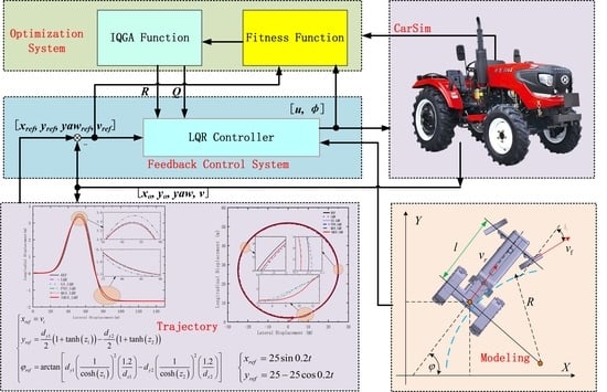
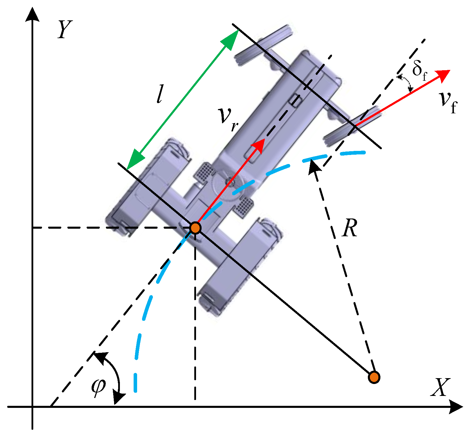
3. Kinematic Model for Wheeled Tractors

As shown in Figure 1, the model used in this paper is a single-track kinematic model of a wheel tractor based on Ackermann steering. The differential equations of motion for the wheel tractor are given in Equation (1).
x ˙ r e a r y ˙ r e a r φ ˙ = cos φ sin φ tan δ f / l v r
where (x, y) are the coordinates of the rear-axle-center of the wheeled tractor, φ is the heading angle of the wheeled tractor, δ f is the front wheel deflection angle, v r is the rear-axle-center speed of the wheeled tractor, v f is the front-axle-center speed of the wheeled tractor, l is the wheelbase, R is the rear wheel steering radius.
The system is a non-linear continuous system. The linearization of the differential Equation (1) for the system gives the Equation (2) of state:
X ˜ ˙ = A X ˜ + B u ˜
where, A = 0 0 v r sin φ r 0 0 v r cos φ r 0 0 0 , B = cos φ r 0 sin φ r 0 tan δ f / l v r / l cos 2 δ r , X ˜ = X X r ,   u ˜ = u u r , and the subscript r indicates the reference value.
The discretization of Equation (2) yields Equation (3) for the system after linearization and discretization.
X ˜ k + 1 = A k X ˜ k + B k u ˜ k
In the above equation, A k = 1 0 v r Tsin φ r 0 1 v r Tcos φ r 0 0 1 , B k = Tcos φ r 0 Tsin φ r 0 T tan δ f l v r T l cos 2 δ r the wheeled tractor position and heading angle of the kinematic model in Equation (3) match very well with the CarSim output for the same speed and front wheel deflection input [25], i.e., this model is a good reflection of the kinematic characteristics of the wheeled tractor while driving.

4. LQR-Based Trajectory Tracking Control Algorithm

4.1. Linear Quadratic Optimal Control Principle

The task of the LQR in trajectory tracking is to make the actual state of the system [x, y] closely follow the system’s reference state under the action of the control quantity u* and to minimize the evaluation function J of the system. This allows the unmanned wheel tractor to maintain the system state components close to the equilibrium without consuming too much energy if the system state deviates from the equilibrium state for any reason.
The quadratic evaluation function is shown in Equation (4).
J = 1 2 k = 0 N 1 X ˜ T k Q X ˜ k + u T k R u k + 1 2 x N r N T Q 0 x N r N
where Q, R, and Q0 are the weight matrices, Q = q 1 0 0 0 q 2 0 0 0 q 3 ,   R = r 1 0 0 r 2 , Q 0 = q 4 0 0 0 q 5 0 0 0 q 6 , q1, q2, q3, q4, q5, q6, r1 and r2 are the coefficients to be optimized, and xn and rn are the terminal states and reference terminal states, respectively.
The control volume u* at moment k of the driverless car is u * = u k + Δ u k   ,   Δ u k = K X ˜ , where u k is the reference output at moment k, Δ u k is the feedback control quantity, and K is the feedback coefficient. When using Matlab for simulation, K can be obtained from Equation (5).
K , S , E = d l q r A k , B k , Q , R
The problems faced by the LQR design control law are, on the one hand, that the values of the LQR parameters require the extensive development experience of engineers and technicians, and a lot of time is needed for the human adjustment of the parameters for multiple degrees of freedom; on the other hand, because the LQR cannot directly deal with the constraint problems in the multivariate control process and when calculating the optimum for a fixed time in the future, it only calculates once and executes all the calculated control sequences; the errors generated during execution and the impact of disturbances on the system are not considered. The optimization of the power matrix parameters of the LQR controller of an unmanned wheel tractor using intelligent algorithms has therefore become a topical concern in the field of optimization algorithms in recent years, and the robustness of wheel tractor trajectory tracking systems can be improved by adding constraints to the optimization search process of the Q and R parameters.

4.2. Standard QGA

QGA is an evolutionary algorithm that combines quantum computing with GA. QGA uses state vectors to encode chromosomes and quantum logic gates to evolve and update the chromosomes, achieving better results than traditional GA.
The quantum revolving gate used in QGA is defined in Equation (6).
U θ i = cos θ i sin θ i sin θ i cos θ i
The update process is as α i β i = U θ i α i β i = cos θ i sin θ i sin θ i cos θ i α i β i .
α and β are two amplitude constants that conform to equation α 2 + β 2 = 1 .
Quantum states are encoded using a binary, and two quantum states are encoded using one quantum bit. The chromosomes encoded using quantum bits are as follows.
q i n = α 11 n β 11 n α 12 n β 12 n α 1 k n β 1 k n α 21 n β 21 n α 22 n β 22 n α 2 k n β 2 k n α m 1 n β m 1 n α m 2 n β m 2 n α m k n β m k n
A quantum bit chromosome can represent multiple states simultaneously, allowing the algorithm to have better population diversity and higher computational parallelism than GA. The algorithm uses a quantum revolving gate operation for individual updates, which effectively increases the convergence speed of the algorithm. However, in the standard QGA, the rotation angle obtained from the table look-up is constant, which is not conducive to evolution in the direction favorable to the optimal determination of the solution, resulting in slow convergence and a long computation time; in addition, in the standard QGA, there is no quantum crossover, mutation, and catastrophe, the chromosomes in the population are all independent of each other, the structural information among individuals cannot be fully utilized, and the algorithm is prone to fall into local optimal solutions. Therefore, the standard QGA needs to be improved to increase the diversity of the population; as pointed out in the literature [26,27], QGA is suitable for solving combinatorial optimization problems, even only for solving backpack problems, but not for solving the optimization problems of continuous functions, especially multi-peaked functions. The application of QGA to the optimization of the weight parameters of the LQR control is a multi-peaked function optimization problem.

4.3. Improvement Strategies

4.3.1. Quantum Gate Rotation Angle Dynamic Adjustment Strategy

The traditional quantum revolving gate adjustment is set by table look-up, and the values of the rotation angles are fixed, lacking theoretical guidance and with obvious limitations; if the magnitude is too small, it affects the convergence speed, while too large leads to prematureness. The literature [28] proposes the random dynamic generation of rotation angles within a range. It experimentally demonstrates that this strategy is superior to fixed rotation angles but is highly random. In this paper, an adaptive dynamic rotation angle step adjustment mechanism is introduced, and the algorithm is optimally designed to adjust the rotation angle required for individual evolution promptly in the face of diverse fitness values, ensuring a timely jumping out of the local optimum and good performance in the global stage of finding the optimum.
QGA mainly occurs through the adjustment of the quantum gate to find the optimal solution. The basic idea is as follows: the contemporary optimal individual’s fitness value f m a x and the current individual i ’s fitness value f i , are compared, if f i > f m a x , then the corresponding rotation angle is adjusted in favor of the i ’s emergence of the direction of evolution or vice versa; then, the evolution in favor of the emergence of the maximum direction is adjusted. Considering the gradient of the objective function at the search point, to make the gradient negatively correlated with the rotation angle step, the new fitness function proposed in the literature [29] considers the rate of change in the objective function. By contrast, the size of the quantum gate rotation angle step determines whether the algorithm can find the optimal solution quickly and accurately. Combining the interference and entanglement of quantum states, we used the following corner step function to realize the dynamic adjustment of the rotation angle:
Δ θ x = s g n M × θ m a x θ m i n · e x p f m a x f x f m a x f m i n + Δ θ 0
where, M = α b α x β b β x ,   α b   , β b T is the optimal probability magnitude within the current population and α x   , β x T is the probability magnitude of the current solution. s g n M takes ± 1 when M = 0, i.e., s g n M determines the direction of the quantum rotation gate. θ m i n is the lower limit of the quantum rotation angle; θ m a x is the upper limit of the quantum rotation angle; f x is the first order gradient of the current individual fitness value; f m a x and f m i n are the maximum and minimum values of the first order gradient of the fitness value of the current population, respectively.   Δ θ 0 is the initial value of the rotation angle. By introducing the factor of gradient change in the exponential function and the fitness value, the rate of change for the objective function can be made to have an opposite trend to the change in the rotation angle step, creating the conditions for the subsequent improvement of QGA to jump out of the local optimal solution.

4.3.2. Diversification Strategies for Populations

Population diversity is critical in all evolutionary algorithms to avoid falling into local optima. In QGA, guided by the evolutionary goal, information is exchanged between individuals to improve the diversity of the next generation of populations. However, when the population size is large, the local optima increases greatly. In addition, it makes local optimum solutions the norm in the face of a multi-peaked optimization problem such as tractor LQR control. Even using single-point mutations, multi-point mutations and quantum catastrophes to regenerate individuals for the next generation of populations is not effective in reducing the impact of local optima on the global optimality-finding ability of evolutionary algorithms. Therefore, there is a need to analyze the population size and distribution trends of individual populations to use different strategies for information interactions to maximize the diversity of the population. As shown in Equation (8), the upper bound of the discrete coefficient C D is C D m a x , and the lower bound is 0, i.e., C D 0 ,   C D m a x .
C D = i = 1 n F i j i = 1 n F i j n n 1 i = 1 n F i j n × i = 1 n F i j F Δ 3 n i = 1 n F i j F Δ 2 n 1.5
The above equation fully accounts for population dispersion and skewed distribution. C D is the dispersion coefficient of the population fitness value;   n   is the number of individuals in the population;   F i j is the fitness value of the ith individual in the population in the jth generation and F Δ is the mean of the fitness function. As C D m a x is dynamically updated, the more it deviates towards 0, the more concentrated and closer to the normal distribution of the population fitness. Otherwise, the population is more discrete. C D m a x considers the degree of dispersion and the deviation characteristics between the whole population and the normal distribution. If there are too many deviations, the population is prone to the trap of local optimality for the algorithm. In the LQR-controlled optimization problem of this paper, particular attention needs to be paid to the evolutionary process for both types of populations. Assuming that the threshold μ generally takes values in the range (0.01~0.3), during each iteration, if the value is between (0,   0.15 C D m a x ], the population falls into a local optimum and must be perturbed for this generation. If the value of C D is between ( 0.15 C D m a x , 0.3 C D m a x ], then the population is in a discrete critical state and needs to be given a small perturbation. If the value of C D is between ( 0.3 C D m a x , C D m a x ], then the population is in a normal iteration.
For a critical state population, if the angle of rotation of the quantum non-gate variation is too large, it is easy to make the population, which is already close to the optimal value, further away from the optimal value, resulting in the loss of good populations. Therefore, this paper uses the Hadamard gate to perform the mutation operation. The Hadamard gate is used to apply a slight rotation to the chromosomes to prevent the generation of the local optimal solutions and increase population diversity.
If a quantum bit is denoted as cos θ i j sin θ i j , the variation can be carried out according to Equation (9) [30].
1 2 1 2 1 2 1 2 cos θ i j sin θ i j = cos θ i j + π 4 2 θ i j sin θ i j + π 4 2 θ i j
The angle of variation for the Hadamard gate is π 4 2 θ i j , and the variables i and j are the jth position of the i th chromosome. In the case of the LQR control, the critical-state population requires particular attention because the tractor is subjected to many operating conditions. If the angle of variation is too large, it can easily lead to population oscillations and cause the optimal individuals to evolve in the opposite direction. The critical state populations, therefore, need to be stable.
For the populations that must be perturbed, the idea of adding chaotic perturbation optimization, referring to the literature [31], increases the algorithm population’s diversity, thus jumping out of the local optimum. In this paper, the perturbation function is implemented using Tent mapping. The Tent expression is shown in Equation (10).
y k + 1 = 2 y k mod 1 0 y k 0.5 2 2 y k mod 1 0.5 < y k 1
However, the Tent mapping iterative sequence is short and unstable, and a random perturbation needs to be applied to make the sequence x k jump out of the minimum period to complete the chaotic state again. The conventional Tent mapping appears as a minimum period point, mainly in the case of x k = x k a ,   a = 1 ,   2 ,   3 ,   4 ,   5 . In this paper, a random perturbation is performed by Equation (11).
y k + 1 = 2 y k + 0.2 r a n d 0 , 1 mod 1 0 y k 0.5 2 2 y k + 0.2 r a n d 0 , 1 mod 1 0.5 < y k 1
The above equation allows a new n×m dimensional probability magnitude perturbation matrix to be formed, and a new population is generated by superimposing each column vector with the probability magnitude matrix of the population. Finally, the chaotic perturbations are traversed to improve the diversity of the new population and the accuracy of the subsequent search.

4.4. Construction of the Fitness Function

In GA, a chromosome corresponds to a set of coefficients in the weights Q, R, and Q0. In order to make the tracking process smoother, a speed constraint and a front wheel deflection constraint are required, as in Equation (12).
v r e a r , min v rea r v r e a r , max δ f , min δ f δ f , max Δ v min Δ v r e a r Δ v max Δ δ f , min Δ δ f Δ δ f , max
To simplify the form, let U = u * ,   Δ u k T , then Equation (12) can be expressed as U min U U max . Since LQR cannot deal with the constraint problem directly, the constraint needs to be put into the fitness function of QGA.
From this, the fitness function of IQGA can be constructed as Equation (13).
F m i n = 1 2 k = 0 N 1 X ˜ T k Q X ˜ k + u ˜ T k R u ˜ k + 1 2 x N r N T Q 0 x N r N , U U m i n , U m a x                                                                     1 2 k = 0 N 1 X ˜ T k Q X ˜ k + u ˜ T k R u ˜ k + 1 2 x N r N T Q 0 x N r N + ε 2 , U , U m i n U m a x , +
where ε 2 is a penalty factor of a larger value. When the calculated output does not satisfy the constraint, the population is guided to evolve towards satisfying the constraint by adding a penalty factor ε 2 to the fitness function to penalize the chromosome and increase its probability of being eliminated.

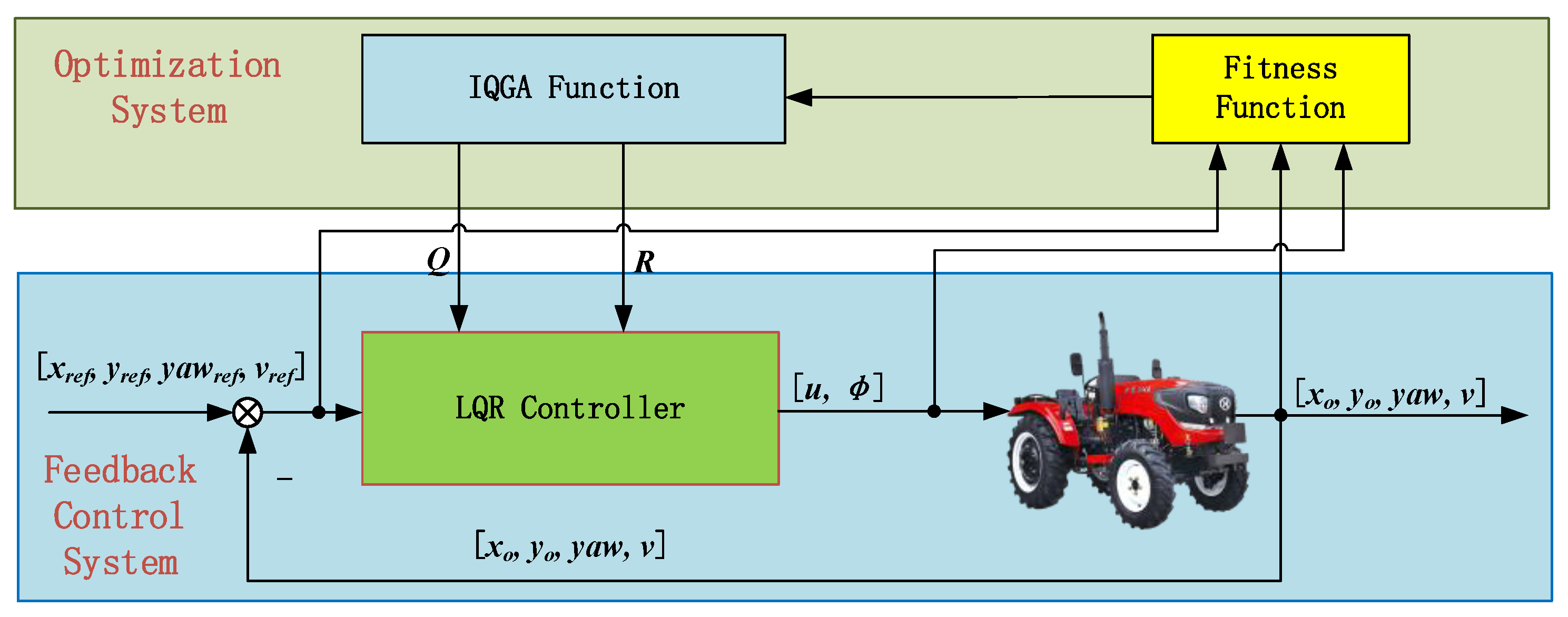
4.5. Algorithms in This Paper

The principle of the control system parameter optimization based on IQGA is shown in Figure 2. According to decentralized coordinated control theory and classical inner and outer loop control system theory, the basis of unmanned wheeled tractor autopilot control is the wheeled tractor speed and heading angle control. A decoupled decentralized controller design is carried out for the wheeled tractor speed and heading angle channels, and then the control quantities are input to CarSim through the role of synergy to form a decentralized coordinated control loop to achieve control; the output signal, error signal, and control quantity signal are input to the adaptation function The output signals, error signals, and control signals are input to the fitness function. The control parameters are optimized through IQGA to form an optimization loop, which forms the optimized control system.

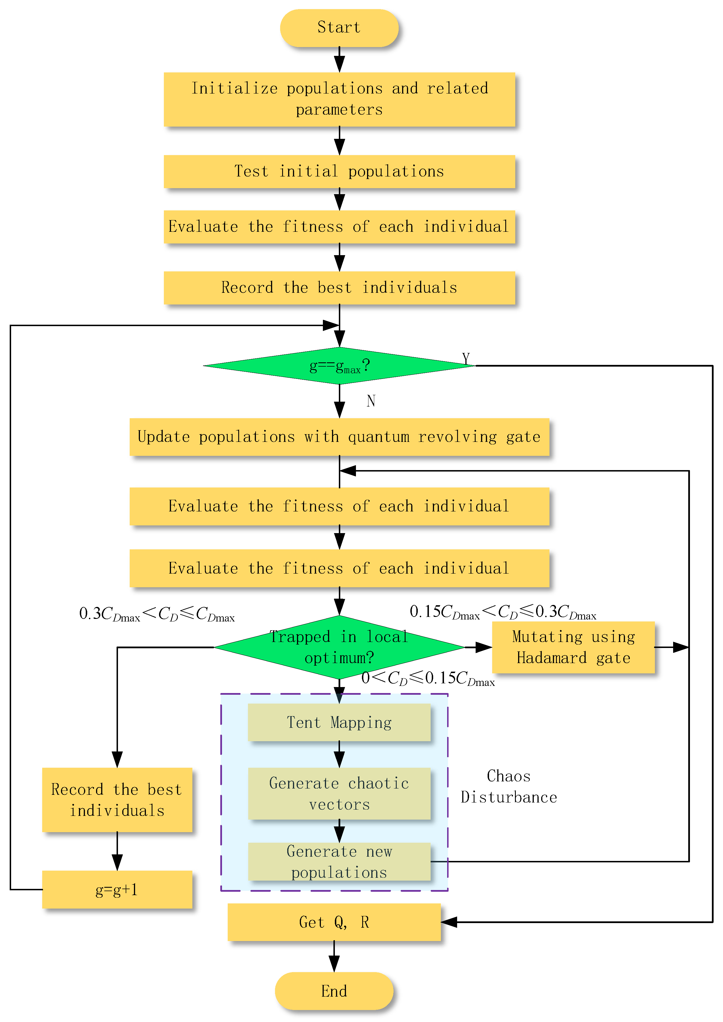
4.6. Optimization Algorithm Process

As shown in Figure 3, the IQGA process is mainly divided into the following steps:
  • Population initialization
First, set the population size Sizepop and the length of the quantum chromosome Lenchrom, and then divide the population space into several segments of the quantum chromosome with the same probability to reduce the number of iterations for population evolution. Set the number of evolutionary generations g = 0 to generate a new initial population P0.
2.
Fitness measurement
According to the lateral displacement, longitudinal displacement, heading angle, speed, and other parameters uploaded by the tractor combined with the fitness function in Equation (13), each chromosomal individual in the population is measured once for its fitness. The optimal fitness and its corresponding chromosomal individual are recorded and used as the basis for the evolution of the next generation.
3.
Judgment of the number of iterations
When judging whether g has reached the predetermined number of iterations, if yes, execute step 7; if not, execute step 4.
4.
Dynamic updates using the Quantum Revolving Gate
The dynamic update of the quantum revolving gate for the population is according to Equation (7).
5.
Fitness measurement
The fitness of each chromosome individual in the population is measured once, and the optimal fitness and its corresponding chromosomal individual are recorded and used as a basis for the evolution of the next generation.
6.
Three different operations are performed according to the standard deviation coefficient
Calculate the standard deviation coefficient CD. If 0.3CDmax < CDCDmax, record the optimal fitness and corresponding chromosome individuals and serve as the basis for next-generation evolution. g = g + 1. Execute step 3. If 0.15CDmax < CD ≤ 0.3CDmax, the Hadamard gate mutation is performed according to Formula (9). Execute step 5. If 0 < CD ≤ 0.15CDmax, according to Formulas (10) and (11), the chaotic vector is generated and the probability amplitude perturbation matrix is formed, and then the probability amplitude perturbation matrix and the probability amplitude matrix of the population are superposed to generate a new population. Execute step 5.
7.
End the program
Obtain Q, R, and end the optimization process.

5. Experimental Results and Analysis

5.1. Experimental Environment

Intel (R) Core (TM) i7-8700K CPU @ 3.70 GHz, Memory: 16.0 GB, Windows 11 Operating System. The algorithms were run in a MATLAB 2020a, CarSim 2020.0 development environment for joint simulation.

5.2. Experimental Data and Parameter Selection

In this paper, the traditional LQR (Trad_LQR), GA, PSO, QGA, and other algorithms and IQGA are simulated and compared to test and verify the effectiveness and feasibility of the proposed IQGA for the optimization of the wheel tractor trajectory tracking control system. The relevant parameters of each algorithm are set in Table 1.

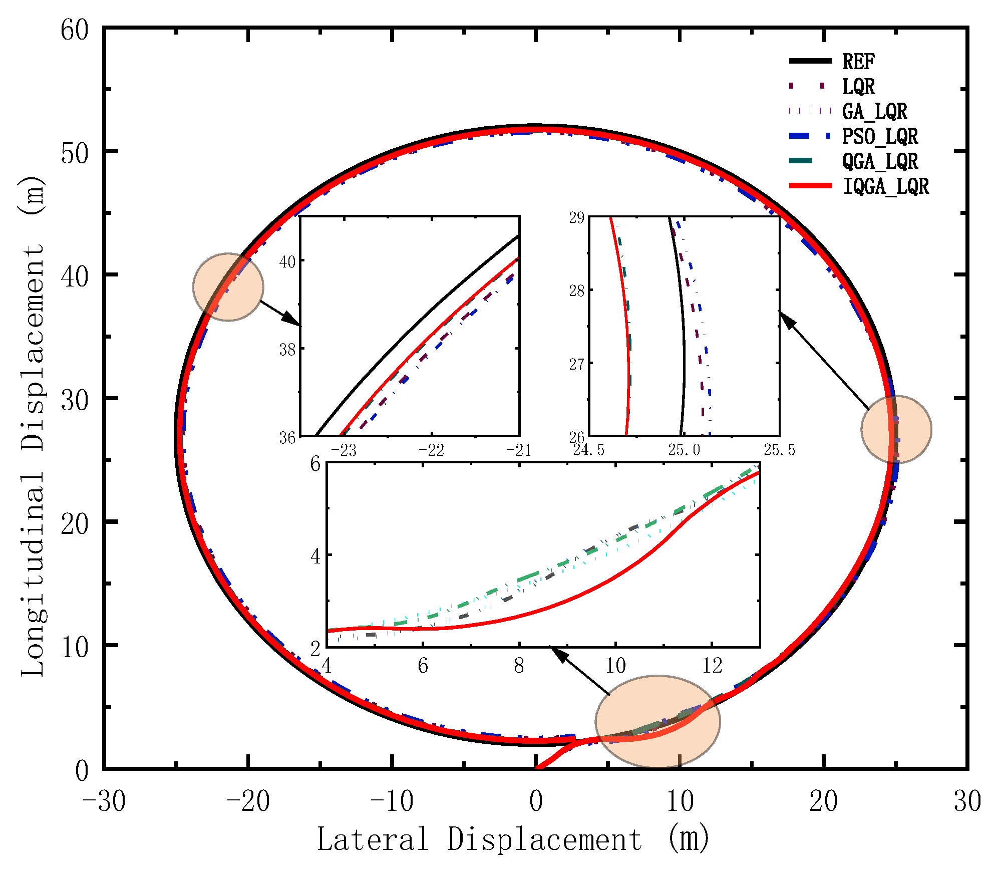
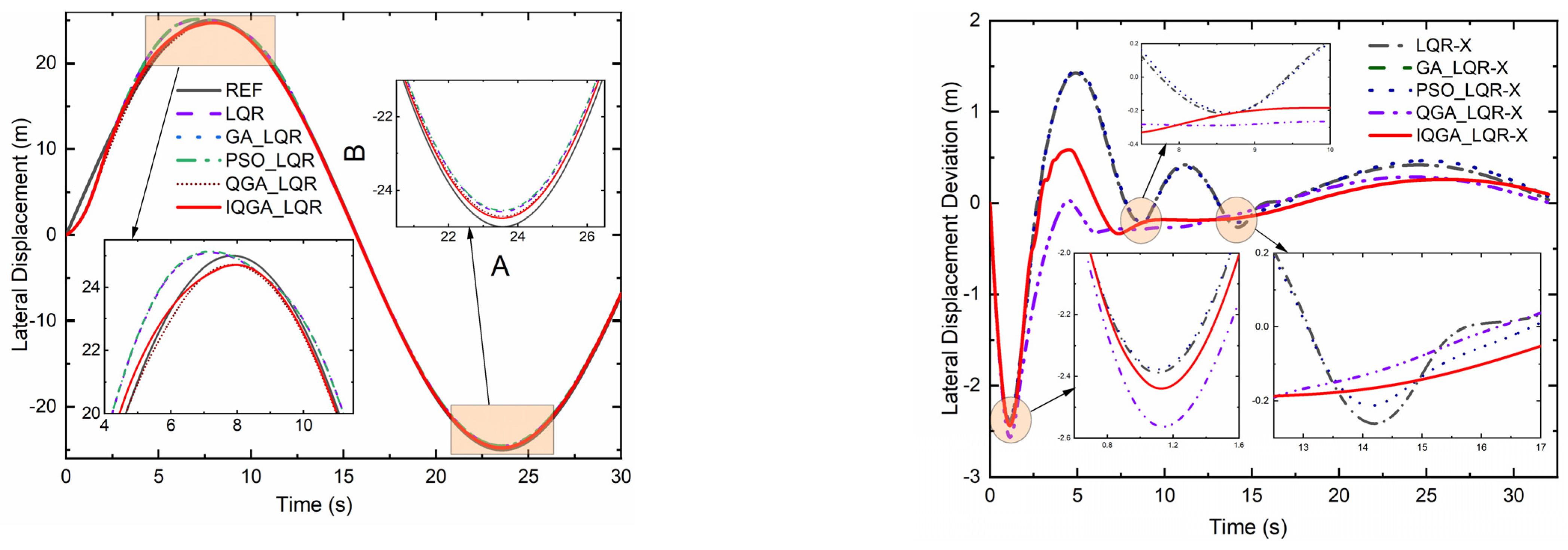
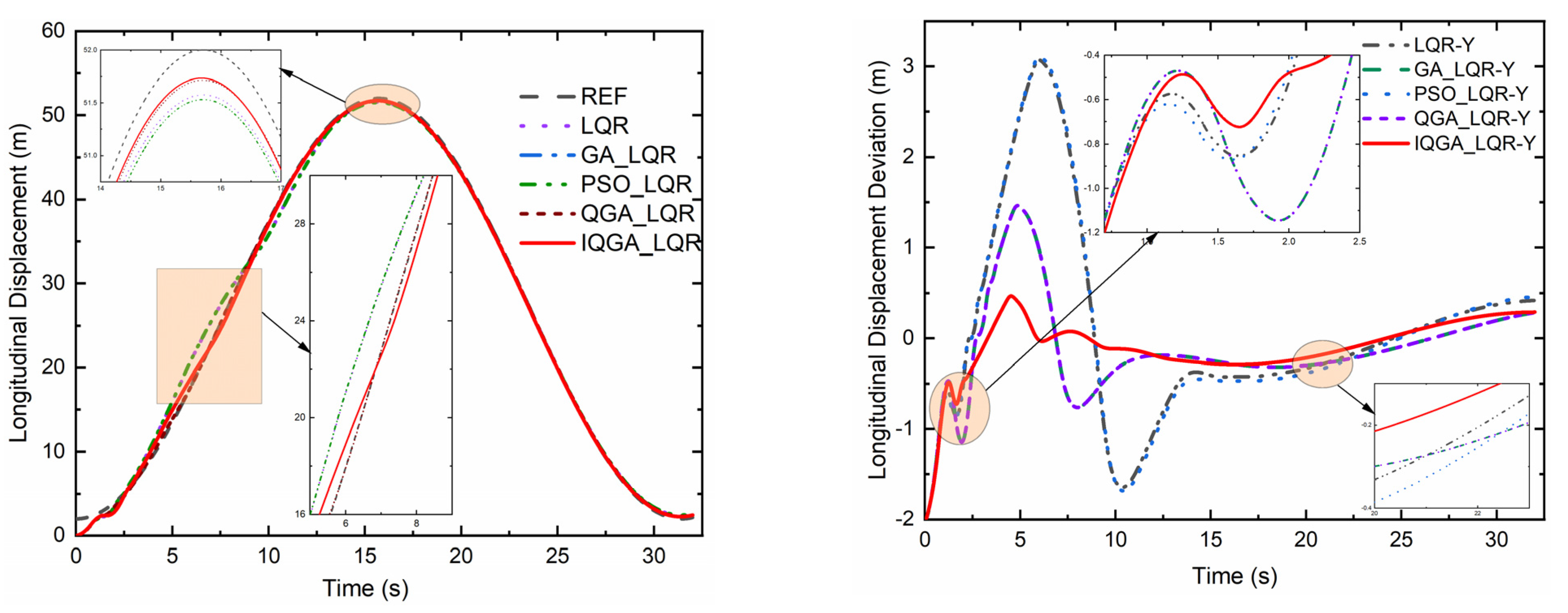
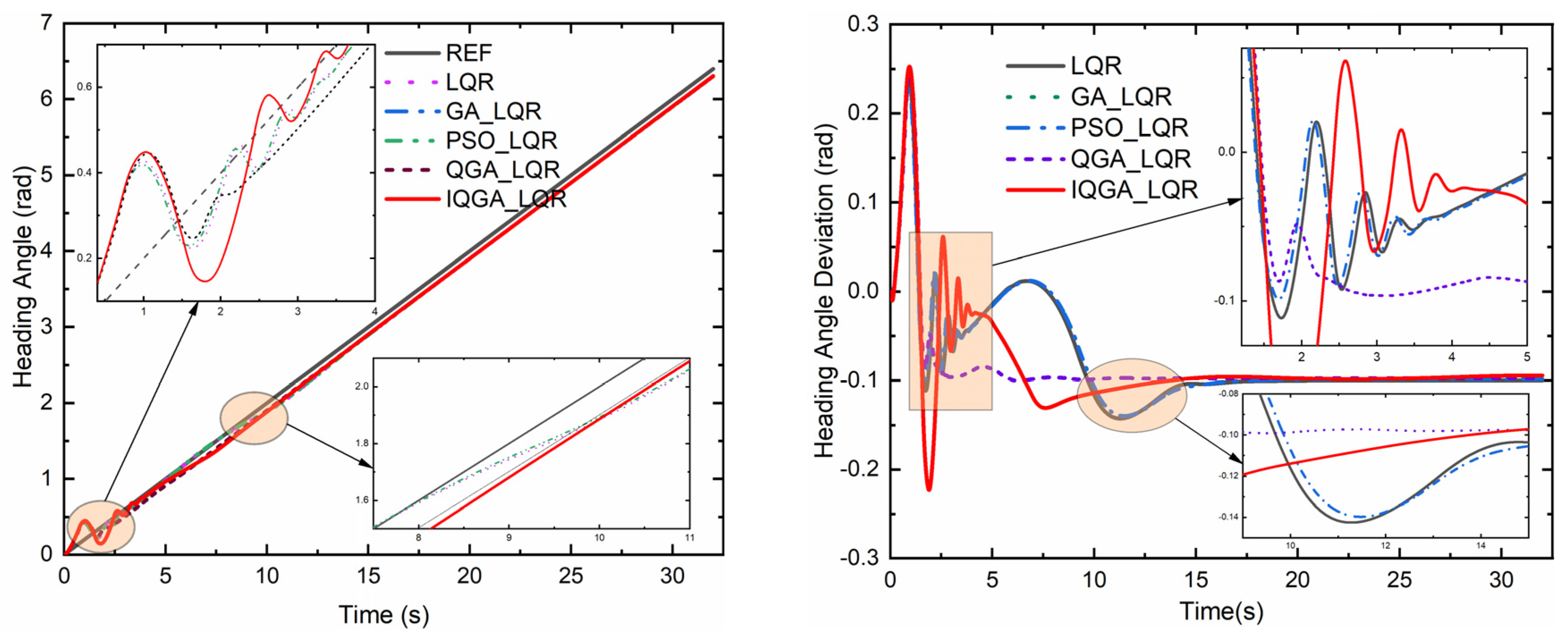
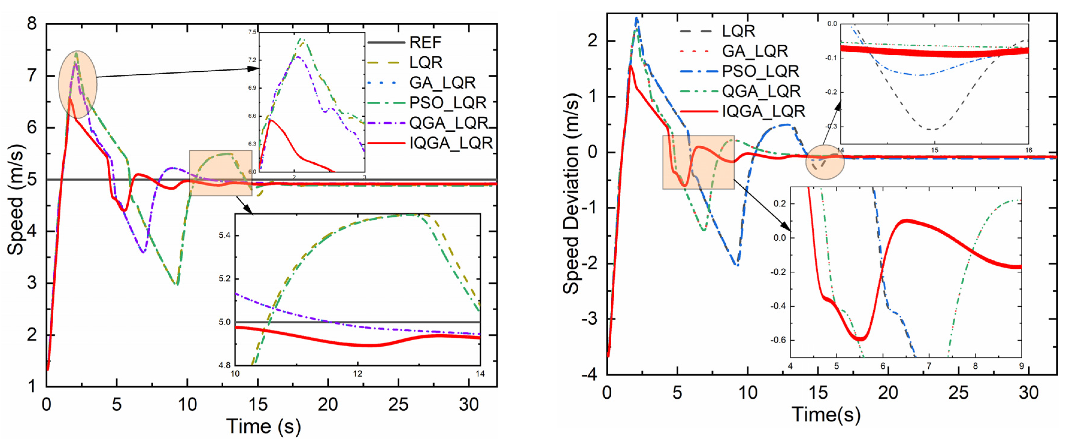
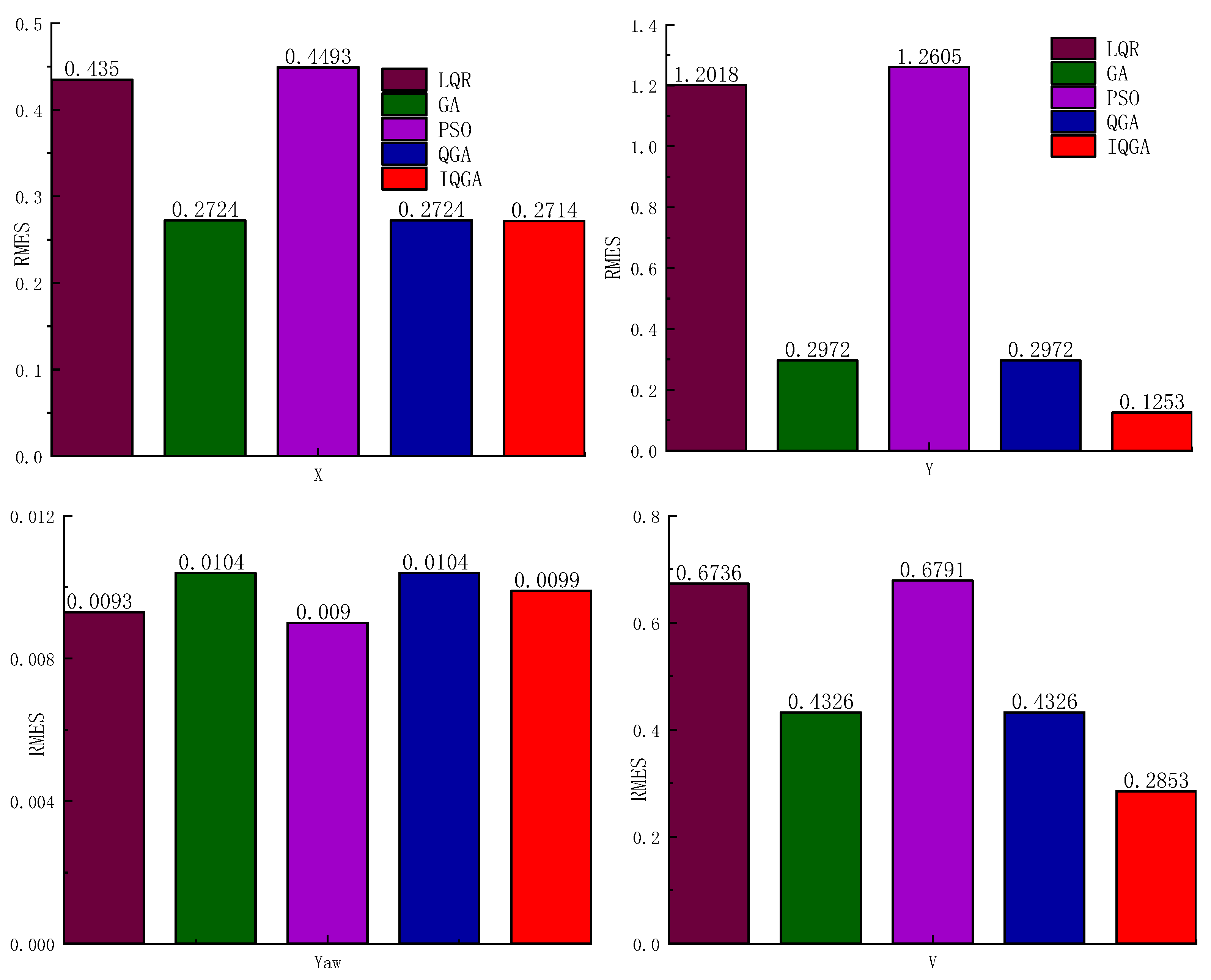
5.3. Tracking a Circular Trajectory

To verify the performance of the designed trajectory tracking controller, we simulated and tested its tracking capability while tracking different trajectories. The kinematic model-based trajectory tracking controller is mainly used for the low-speed working condition of the tractor. According to its motion characteristics, a circular trajectory is first selected for tracking.
For a circular track, the reference speed V is 5 m/s, the reference front wheel angle is 0.106 rad, the radius is 25 m, the angular velocity is 0.2 rad/s, the center coordinate is (0, 25) m, and the reference track equation is in Equation (14).
x r e f = 25 sin 0.2 t y r e f = 25 25 cos 0.2 t
The simulation results of the tracking circular trajectory are shown in Figure 4.
Tractor transverse and longitudinal displacements determine the degree of crop neatness and are often used as visual indicators to evaluate the tractor’s operational control performance. For this reason, the time domain response of the tractor displacement is compared and analyzed in this section, and the response curves are shown in Figure 5 and Figure 6, respectively.
The lateral and longitudinal displacements and their deviations using each controller are plotted in Figure 5 and Figure 6. It can be noted that the peak transverse and longitudinal displacements of the proposed control strategy are significantly reduced, and the deviation fluctuations tend to be flat compared to the other four control methods. Figure 7 and Figure 8 show the heading angle, tractor speed, and their deviations. In Figure 7, the heading angle of the IQGA-LQR control method enters the steady state at the earliest compared to other optimization methods. In Figure 8, the tractor speed of the IQGA-LQR control method has a slight jitter in some periods, but the overall deviation is always the smallest and the first to enter the steady state.
RMSE belongs to the L2 norm, which is more sensitive to outliers and is widely used in engineering measurements. RMSE can measure the deviation between the actual motion trajectory of the tractor and the reference motion trajectory. The RMSE compares the advantages and disadvantages of the Trad_LQR, GA-LQR, PSO-LQR, QGA-LQR, and IQGA-LQR control methods.
To qualitatively examine the control performance of the IQGA-LQR control strategy, a comparison among the maximum, minimum, and RMSE results for each deviation is derived using the conventional LQR, GA-LQR, PSO-LQR, QGA-LQR, and IQGA-LQR methods given in Table 2.
Compared with the conventional LQR, the IQGA-LQR controller reduced the maximum value of the lateral displacement deviation and RMSE value of the tractor by 79.79% and 37.61%, respectively, and increased the minimum value of the lateral displacement deviation by 7.35%, with little increase compared to the overall result. The maximum value and RMSE value of the longitudinal displacement deviation decreased by 84.81% and 89.57%, respectively, and the minimum value of longitudinal displacement deviation was the same. The maximum value of the heading angle deviation and RMSE value increased by 3.17% and 6.45%, respectively, but the minimum value of the heading angle deviation decreased by 29.59%, which is a larger decrease; the maximum value of the speed deviation and RMSE value decreased by 34.84% and 57.65%, respectively, and the minimum value of speed deviation increased slightly by 0.7%, which is negligible.
Compared with GA-LQR, the IQGA-LQR controller resulted in a larger decrease in the maximum value of the lateral displacement deviation of the tractor, with a reduced value of 50.74%. By contrast, the RMSE value and the minimum value of the lateral displacement deviation increased, by 0.37% and 5.09%, respectively. The maximum value of the longitudinal displacement deviation and the root-mean-square error value were greatly reduced by 68.08% and 57.84%, respectively, while the minimum value of the longitudinal displacement deviation remains unchanged; the maximum value of the heading angle deviation, root-mean-square error value and the minimum value of transverse displacement deviation was reduced by 3.44%, 54.98%, and 4.81%, respectively. The maximum value of the speed deviation and RMSE value were reduced significantly by 30.36% and 34.05%, respectively. In comparison, the minimum value of the speed deviation increased by 0.7%, which is relatively small and can also be ignored.
Compared with PSO-LQR, the IQGA-LQR controller reached the maximum value of lateral displacement deviation, and the RMSE value of the tractor had a large reduction by 80.11% and 39.59%, respectively, while the minimum value of the lateral displacement deviation did not increase much, and its upward value was 7.84%. The maximum value and RMSE of longitudinal displacement deviation decreased by 85.01% and 90.06%, respectively, while the minimum value of longitudinal displacement deviation increased by 40%; the maximum value and RMSE of the heading angle deviation increased by 5.81% and 10%, respectively, while the minimum value of the heading angle deviation decreased by 28.18%. The maximum value of the speed deviation and RMSE decreased by 36.25% and 57.99%, respectively, while the minimum value of the speed deviation increased slightly by 0.7%.
Compared with QGA-LQR, the IQGA-LQR controller reduced the maximum value of the lateral displacement deviation of the tractor by 50.75%. The RMSE value did not change much and was reduced by 0.37%. In contrast, the minimum value of the lateral displacement deviation increased, and its reduction value was 20.37%. The maximum value and RMSE of the longitudinal displacement deviation decreased by 68.08% and 57.84%, respectively, while the minimum value of the longitudinal displacement deviation did not change; the maximum value, minimum value, and RMSE of the heading angle deviation decreased by 3.44%, 54.98%, and 4.81%, respectively, with the minimum value of the heading angle deviation decreasing by a larger extent. The maximum value of speed deviation and the RMSE value decreased by 30.36% and 34.05%, respectively, and the minimum value of speed deviation showed a small increase with an upward value of 0.7%.
The RMSE values of the kinematic states under circular trajectories are given in Figure 9, from which it can be seen that among the four compared data, the IQGA-LQR RMSE data are the smallest for three and slightly larger for one. These three data are the RMSE values of lateral displacement, longitudinal displacement, the heading angle, and velocity, respectively; the slightly larger one is the lateral displacement of the RMSE value. Figure 10 gives the RMSE values of the motion states under the double-shifted trajectory, from which it can be seen that all four RMSE data of IQGA-LQR are the smallest among the four compared data; therefore, IQGA-LQR is the optimal choice from the RMSE point of view.
From the analysis of the typical numerical decrease in percentage, it can be inferred that the IQGA-LQR control strategy has a better control effect. Obviously, the tractor system controlled by this method achieved better lateral and longitudinal operation accuracy and speed tracking when performing agricultural tillage and harvesting. Thus, the effectiveness of the proposed LQR method optimized by IQGA is verified.
The controller parameters are shown in Table 3.

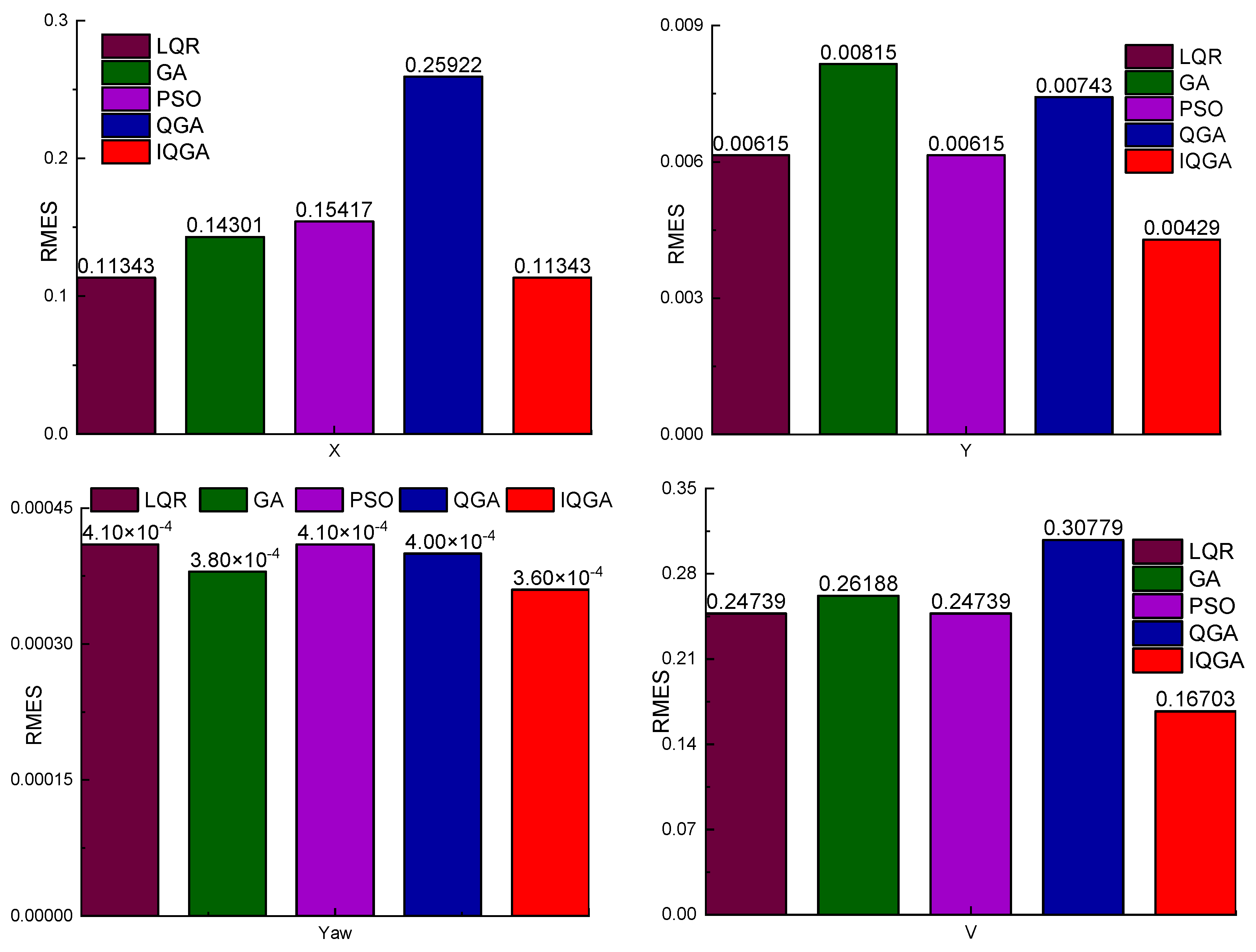
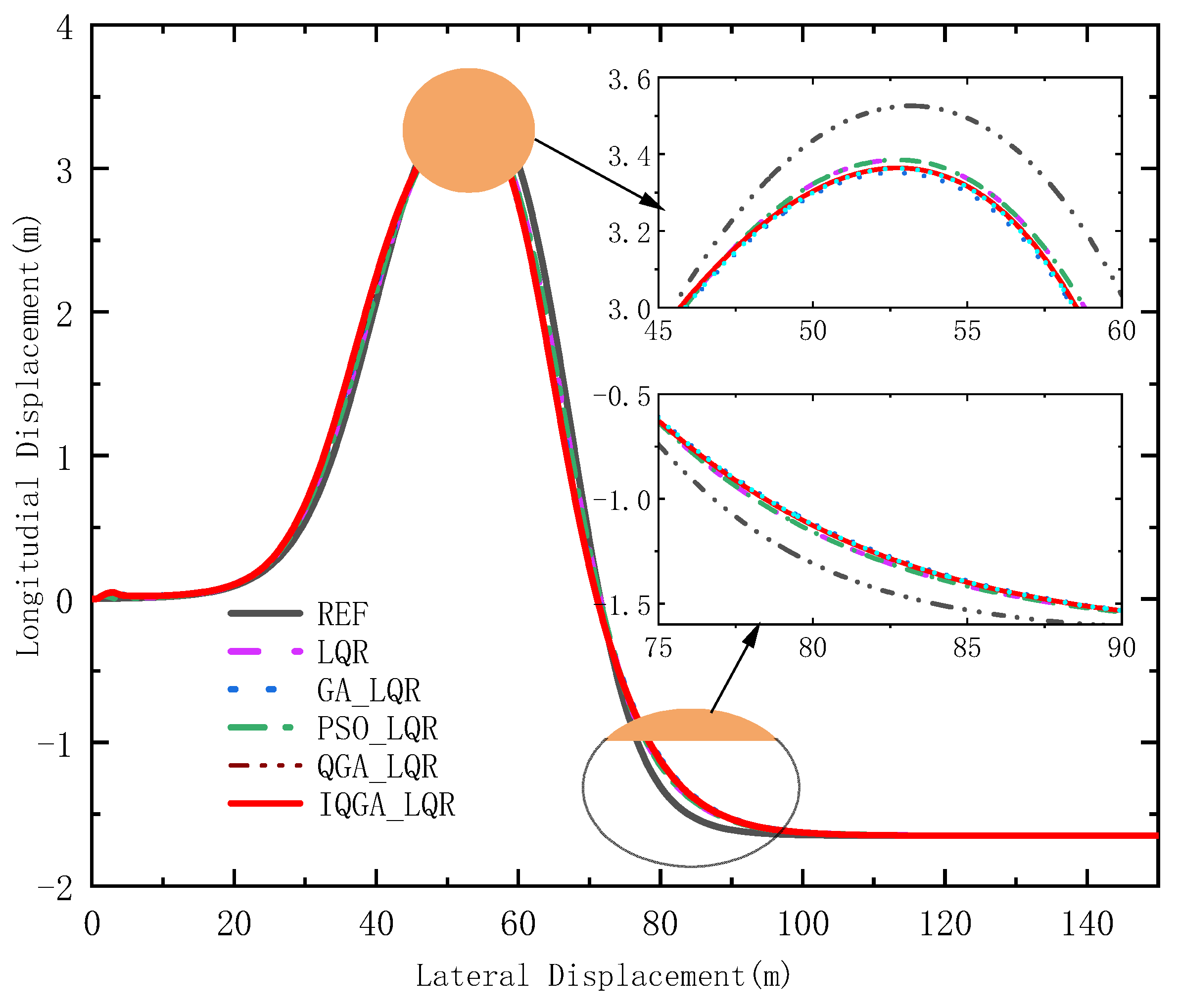
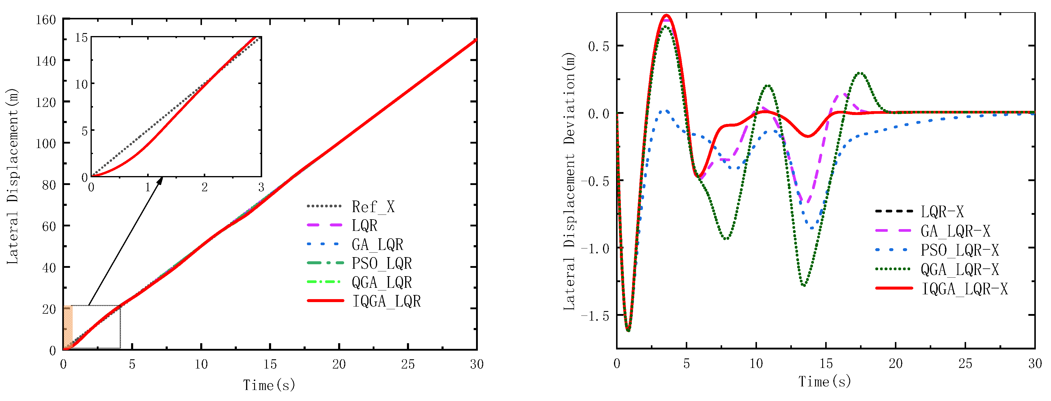
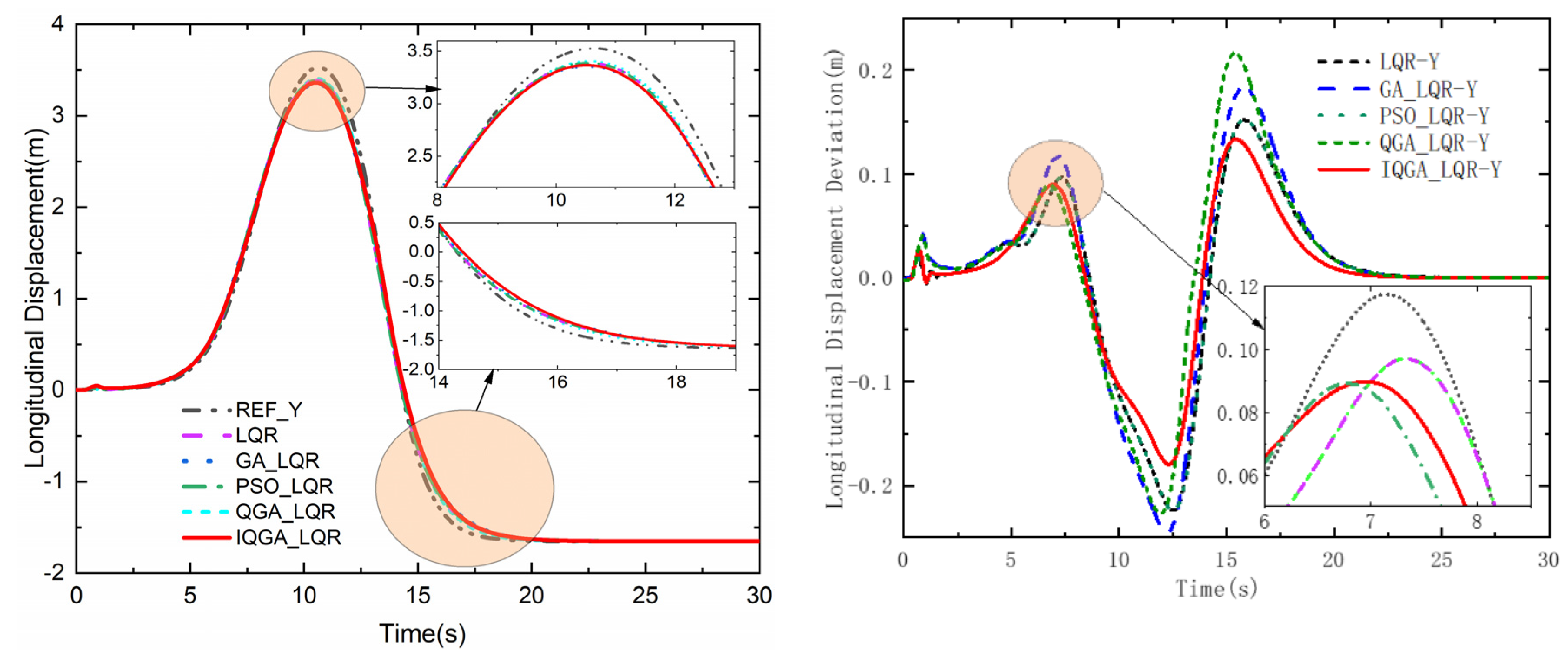
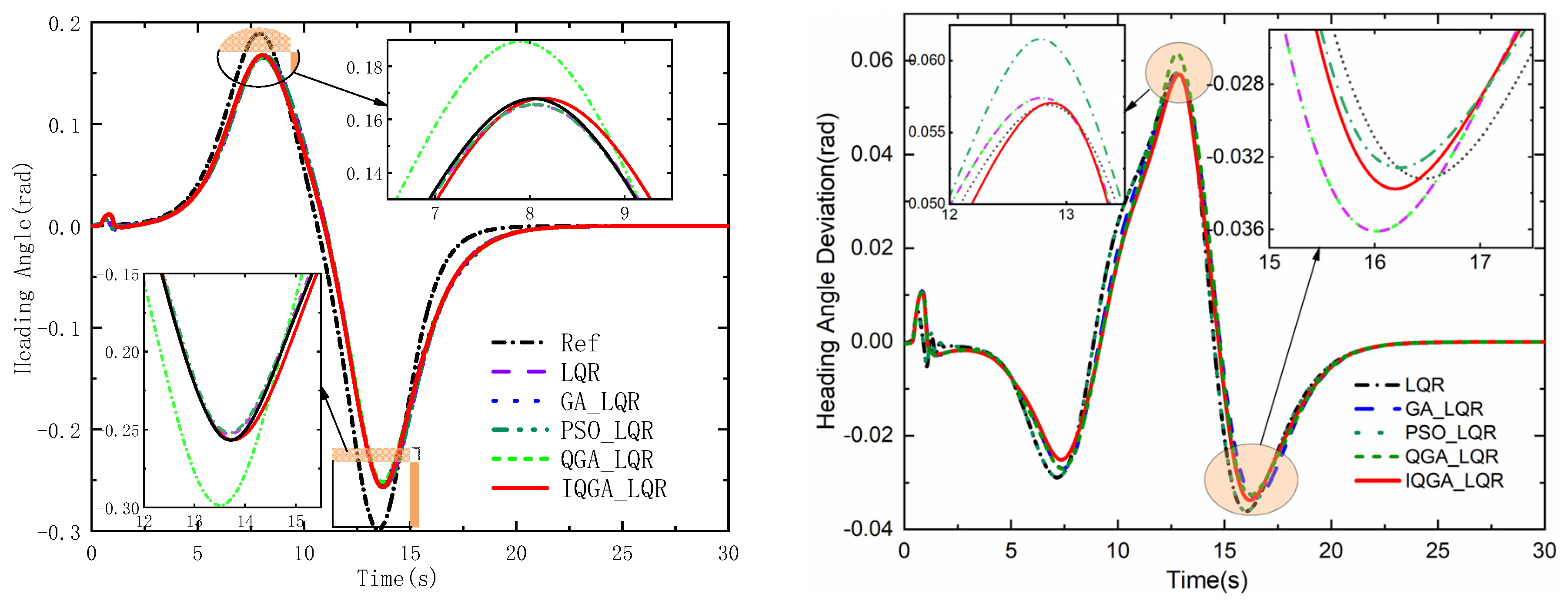
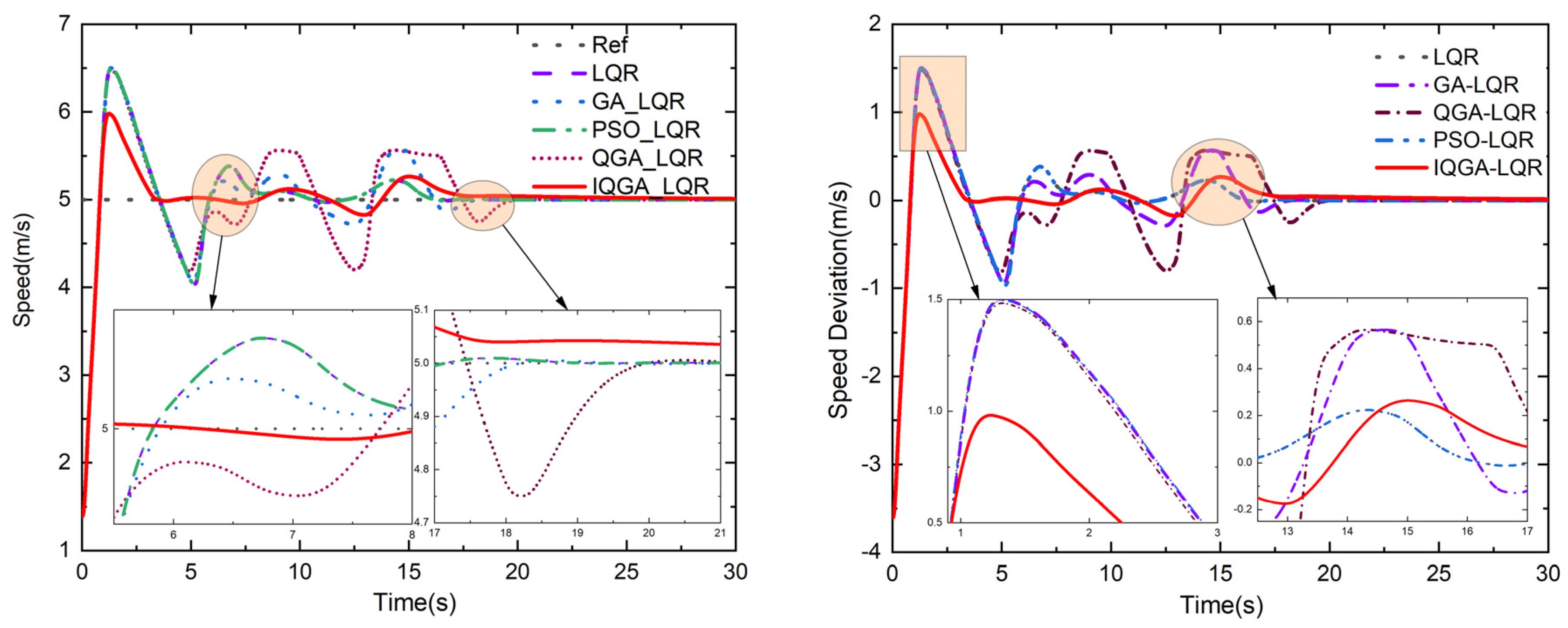
5.4. Tracking Double Shift Trajectory

When the tractor is working, the evaluation of the controller is not only the tracking accuracy but also needs to focus on the stability of the tracking process. In the test of the wheeled tractor driving stability, the double-shifted line working condition is a test method used more frequently. There are also more scholars [32,33,34] to test the trajectory tracking ability of unmanned wheeled tractors with double-shifted trajectories. Therefore, in this paper, the designed LQR controller was simulated and tested using the double-shifted trajectory [35].
For the double-shift line trajectory, the reference tractor speed v is 5 m/s, and the reference trajectory is Equation (15).
x r e f = v t y r e f = d y 1 2 1 + tanh z 1 d y 2 2 1 + tanh z 2 φ r e f = arctan d y 1 1 cosh z 1 2 1.2 d x 1 d y 2 1 cosh z 2 2 1.2 d x 2
where,   z 1 = 2.4 25 X 27.19 1.2 , z 1 = 2.4 21.95 X 56.46 1.2 ,   d x 1 = 25 ,   d x 2 = 21.95 ,   d y 1 = 4.05 ,   d y 2 = 5.7 .
The radius of the curvature of this double shift trajectory is calculated by Equation (16). It gives the reference front wheel rotation angle: δref = arctan (l/R). The simulation results of the double-shifted reference trajectory are shown in Figure 11.
R = 1 + d y r e f d x r e f 2 3 2 d 2 y r e f d x r e f 2
Similar to the analysis of circular trajectories, to qualitatively examine the control performance of the IQGA-LQR control strategy, a comparative study among the simulation results of deviation maxima, minima, and RMSEs derived with the conventional LQR, GA-LQR, PSO-LQR, QGA-LQR, and IQGA-LQR methods is given in Table 4.
Compared with the conventional LQR, the IQGA-LQR controller left the maximum value, minimum value, and RMSE value of lateral displacement deviation of the tractor unchanged; the maximum value, minimum value, and RMSE value of the longitudinal displacement deviation are reduced by 12.32%, 19.82%, and 29.51%, respectively; the maximum value, minimum value, and RMSE value of the heading angle deviation are reduced by 0.52%, 6.37%, respectively, and the RMSE value is the same. The maximum and minimum values for the deviation of the heading angle decreased by 0.52% and 6.37%, respectively, and the RMSE value was the same. The maximum value of the speed deviation was reduced by 34.44%, the minimum value did not change, and the value of RMSE was reduced by 32.5%.
Compared with GA-LQR, the IQGA-LQR controller increased the maximum value of the lateral displacement deviation of the tractor by 3.34%, reduced the minimum value of the lateral displacement deviation and RMSE value by 0.43% and 20.7%, respectively, reduced the maximum value of longitudinal displacement deviation, and RMSE value by 27.51%, 26.63%, and 47.56%, respectively. The maximum and minimum values of the heading angle deviation had a small increase of 0.35% and 1.81%, respectively, while RMSE values did not change; the maximum and RMSE values of the speed deviation decreased by 34.66% and 36.24%, respectively, and the minimum values of the speed deviation were the same.
Compared with PSO-LQR, the IQGA-LQR controller made the maximum and minimum values of lateral displacement deviation of the tractor slightly increase by 0.22% and 0.1%, respectively, which is almost negligible, and the RMSE value decreased by 26.46%, which is larger; the maximum and minimum values of the longitudinal displacement deviation and RMSE value decreased by 12.32%, 19.82%, and 29.51%, respectively. The maximum and minimum values of longitudinal displacement deviation decreased by 12.32%, 19.82%, and 29.51%, respectively; the maximum and minimum values of the heading angle deviation decreased by 0.52% and 6.37%, respectively, and the RMSE value was the same; the maximum and RMSE values of speed deviation decreased by 34.43% and 32.5%, respectively, and the minimum value of speed deviation did not change.
Compared with QGA-LQR, the IQGA-LQR controller increased the maximum value of the lateral displacement deviation of the tractor by 13.05%, reduced the minimum value of lateral displacement deviation and the RMSE value by 0.38% and 56.25%, respectively; it reduced the maximum value of longitudinal displacement deviation, the minimum value, and RMSE value by 38.41%, 20.85%, 41.89%, respectively. It also reduced the maximum value of the heading angle deviation by 7.15%, increased the minimum value by 3.68%, and kept the RMSE value unchanged. The maximum value of the heading angle deviation decreased by 7.15%, the minimum value increased by 3.68%, and the RMSE value remained the same; the maximum and RMSE values of the speed deviation decreased by 33.83% and 45.74%, respectively, and the minimum value of speed deviation was the same.
Figure 12 and Figure 13 are the transverse and longitudinal displacements of the wheeled tractor, and their deviations use each controller while tracking the double-shift line trajectory. The figures show that the peaks of the transverse and longitudinal displacements of the proposed control strategy are relatively smaller, and the deviations are smaller throughout the process than the other four control methods. Figure 14 and Figure 15 show the heading angle, tractor speed, and their deviations. In Figure 14, IQGA-LQR has relatively smaller deviations at the peak compared to other optimization methods, and the advantage is not so obvious in other stages. In Figure 15, the IQGA-LQR control method of the tractor speed and their deviations are better controlled throughout the control phase, and the deviations are in a relatively small state all the time.
By comparing all system deviations in Table 2 and Table 4, it can be inferred that the IQGA-LQR control strategy has better control effects in four aspects: lateral deviation, longitudinal deviation, heading angle deviation, and speed deviation, thus verifying the higher effectiveness of the proposed LQR method optimized by IQGA.
The controller parameters after IQGA optimization are shown in Table 5.

6. Summary and Prospect

In this paper, a kinematic model of the wheel tractor was built based on the Ackermann steering model, the state weighting matrix in the LQR controller was optimized using IQGA, and finally, a joint simulation was performed using Carsim and MATLAB. The simulation results after comparing the other four optimization algorithms showed that:
(1)
The coefficient matrix selected by IQGA had better tracking accuracy. The lateral position deviation, longitudinal position deviation, and heading angle deviation all tended to be zero, the control effect was better, and the system tended to be stable. Adding constraints to the LQR increases ride comfort. The RMSE of lateral displacement, longitudinal displacement, and the heading angle after tractor stabilization were 0.2714 m, 0.1253 m, and 0.0099 rad, respectively, when the tracking circular trajectory was at 5 m/s. The error of lateral displacement, longitudinal displacement, and the heading angle after tractor stabilization was 0.1134 m, 0.0043 m, and 0.0004 rad, respectively, when tracking a double-shift trajectory at 5 m/s.
(2)
The tracking method designed based on kinematics is suitable for low-speed work scenarios. If the wheeled tractor is tracked at high speed, the situation is more complex when the wheeled tractor’s kinematics cannot meet the actual demand. At the same time, the kinematic modeling of the wheel tractor is simplified, such as linearizing the nonlinear system, ignoring the disturbance term, etc., so some errors in the tracking process are difficult to eliminate. In the subsequent research, we can design the nonlinear trajectory tracking controller based on the wheel tractor dynamics and consider the influence of the wheel tractor’s lateral tilt characteristics, the tire’s slip characteristics, the disturbance term, and other factors.
(3)
The reference trajectory also greatly influences the tracking effect. For example, when the connection point of the trajectory is not derivable, there is an oscillation in the control data when controlling the wheel tractor. Therefore, in the subsequent study, the original reference trajectory can be sampled, and the original reference trajectory can be reprogrammed according to the kinematic constraints of the wheel tractor or wheel tractor dynamics constraints. A trajectory that meets the constraints can be reprogrammed for tracking.

Author Contributions

Methodology, X.F. and J.W.; software, H.W. and L.Y.; formal analysis, H.W. and L.Y.; data curation, X.F. and J.W.; project administration, C.X.; funding acquisition, C.X. All authors have read and agreed to the published version of the manuscript.

Funding

This research was funded by [the National Key Research and Development Program of China], grant number [2016YFD0700400] and Changzhou Science &Technology Program, grant number [CJ20220232].

Data Availability Statement

Data available on request from the authors. The data that support the findings of this study are available from the corresponding author, [Xia, C.], upon reasonable request.

Conflicts of Interest

The authors declare no conflict of interest.

References

  1. Yadav, A.; Gaur, A.; Jain, S.; Chaturvedi, D.; Sharma, R. Development Navigation, Guidance & Control Program for GPS based Autonomous Ground Vehicle (AGV) using Soft Computing Techniques. Mater. Today Proc. 2020, 29, 530–535. [Google Scholar]
  2. Zhang, Z.; Wu, L.; Zhang, W.; Peng, T.; Zheng, J. Energy-efficient path planning for a single-load automated guided vehicle in a manufacturing workshop. Comput. Ind. Eng. 2021, 158, 107397. [Google Scholar] [CrossRef]
  3. Feilong, W.; Shiyong, G. Intelligent Vehicle Path Tracking Algorithm Based on Nonlinear Model Predictive Control. Automob. Technol. 2020, 1–7. [Google Scholar]
  4. Nie, Z.G.; Wang, W.Q.; Zhao, W.Q.; Huang, Z.; Zong, C.F. Dynamic trajectory planning and tracking control for lane change of intelligent vehicle based on trajectory preview. J. Traffic Transp. Eng. 2020, 20, 147–160. [Google Scholar]
  5. Wongsathan, C.; Sirima, C. Application of GA to design LQR controller for an Inverted Pendulum System. In Proceedings of the IEEE International Conference on Robotics & Biomimetics, Bangkok, Thailand, 22–25 February 2009. [Google Scholar]
  6. Rahimi, A.; Ghazi, R. GA-Based Optimal LQR Controller to Improve LVRT Capability of DFIG Wind Turbines. Iran. J. Electr. Electron. Eng. 2013, 9, 167–176. [Google Scholar]
  7. Kafafy, M.; Rabeih, A.; Eldemerdash, S.; Elbutch, A. Active Suspension Design for Passenger Cars Using LQR and GA with PID Controller. SAE Technical Papers, St. Charles, IL, USA, 15–17 May 2007. [Google Scholar] [CrossRef]
  8. Amini, F.; Hazaveh, N.; Rad, A. Wavelet PSO-Based LQR Algorithm for Optimal Structural Control Using Active Tuned Mass Dampers. Comput.-Aided Civ. Infrastruct. Eng. 2013, 28, 542–557. [Google Scholar] [CrossRef]
  9. Mf, A.; Sn, A.; Ak, B. On the ability of sliding mode and LQR controllers optimized with PSO in attitude control of a flexible 4-DOF satellite with time-varying payload. Adv. Space Res. 2021, 67, 334–349. [Google Scholar]
  10. Reddipogu, J.; Elumalai, V. Hardware in the Loop Testing of Adaptive Inertia Weight PSO-Tuned LQR Applied to Vehicle Suspension Control. J. Control. Sci. Eng. 2020. [Google Scholar] [CrossRef]
  11. Li, L.; Qiu, T.; Jia, T.; Chen, C. Stepping quantum genetic algorithm-based LQR control strategy for lateral vibration of high-speed elevator. at-Automatisierungstechnik 2022, 70, 623–634. [Google Scholar] [CrossRef]
  12. Sajid, U.; Wahid, M. Topology Control of wireless sensor network using Quantum Inspired Genetic algorithm. Int. J. Swarm Intell. Evol. Comput. 2015, 4, 121. [Google Scholar] [CrossRef]
  13. Marji, M.; Sumarli, E. Design and Investigation of Fuzzy Control For Independent Full Car Suspension Model in Random Road And Braking Excitation. Int. J. Adv. Sci. Technol. 2020, 29, 20–23. [Google Scholar]
  14. Meng, Y.; Gan, X.; Wang, Y.; Qing, G. LQR-GA Controller for Articulated Dump Truck Path Tracking System. J. Shanghai Jiaotong Univ. (Sci.) 2019, 24, 78–85. [Google Scholar] [CrossRef]
  15. Zhang, W. A robust lateral tracking control strategy for autonomous driving vehicles. Mech. Syst. Signal Process. 2021, 150, 107238. [Google Scholar] [CrossRef]
  16. Yuan, S.; Zhao, P.; Zhang, Q.; Hu, X. Research on Model Predictive Control-based Trajectory Tracking for Unmanned Vehicles. In Proceedings of the 2019 4th International Conference on Control and Robotics Engineering (ICCRE), Nanjing, China, 20–23 April 2019; pp. 79–86. [Google Scholar]
  17. Kanieski, J.; Carati, E.; Cardoso, R. An energy based LQR tuning approach applied for Uninterruptible Power Supplies. In Proceedings of the 2010 First IEEE Latin American Symposium on Circuits and Systems (LASCAS), Foz do Iguacu, Brazil, 24–26 February 2010; pp. 41–44. [Google Scholar]
  18. Ufnalski, B.; Kaszewski, A.; Grzesiak, L. Particle Swarm Optimization of the Multioscillatory LQR for a Three-Phase Four-Wire Voltage-Source Inverter With an $LC$ Output Filter. IEEE Trans. Ind. Electron. 2015, 62, 484–493. [Google Scholar] [CrossRef]
  19. Almeida, P.; Ribeiro, A.; Souza, I.; Fernandes, M.; Fogli, G.; Ćuk, V.; Barbosa, P.; Ribeiro, P. Systematic Design of a DLQR Applied to Grid-Forming Converters. IEEE J. Emerg. Sel. Top. Ind. Electron. 2020, 1, 200–210. [Google Scholar] [CrossRef]
  20. Liu, S.; Wu, W.; Jin, Q.; Zhu, Y. Design Method for Helicopter Flight Control Law Based on Particle Swarm Optimization. J. Nanjing Univ. Aeronaut. Astronaut. 2021, 53, 267–274. [Google Scholar]
  21. Tian, J.; Guo, Q.; Shi, G. Laminated piezoelectric beam element for dynamic analysis of piezolaminated smart beams and GA-based LQR active vibration control. Compos. Struct. 2020, 252, 112480. [Google Scholar] [CrossRef]
  22. Kumar, E.V.; Raaja, G.; Jerome, J. Adaptive PSO for optimal LQR tracking control of 2 DoF laboratory helicopter. Appl. Soft Comput. 2016, 41, 77–90. [Google Scholar] [CrossRef]
  23. Gokul Prassad, S.; Malar Mohan, K. A contemporary adaptive air suspension using LQR control for passenger vehicles. ISA Trans. 2019, 93, 244–254. [Google Scholar] [CrossRef]
  24. Belyaev, A.; Sumenkov, O. Hybrid control algorithm based on LQR and genetic algorithm for active support weight compensation system. IFAC-Pap. 2021, 54, 431–436. [Google Scholar] [CrossRef]
  25. Jianwei, G.; Yan, J.; Wei, X. Model Predictive Control for self-driving Vehicles, 2nd ed.; Beijing Institute of Technology Press: Beijing, China, 2014. [Google Scholar]
  26. Han, K.; Park, K.; Lee, C.; Kim, J. Parallel quantum-inspired genetic algorithm for combinatorial optimization problem. In Proceedings of the Proceedings of the 2001 Congress on Evolutionary Computation (IEEE Cat. No.01TH8546), Seoul, Korea, 27–30 May 2001. [Google Scholar]
  27. Gexiang, Z.; Na, L.; Weidong, J.; Laizhao, H. A Novel Quantum Genetic Algorithm and Its Applicat. Acta Electron. Sin. 2004, 32, 476–479. [Google Scholar]
  28. Zhang, X.F.; Sui, G.F.; Zheng, R.; Li, Z.N.; Yang, G.W. An Improved Quantum Genetic Algorithm of Quantum Revolving Gate. Comput. Eng. 2013, 39, 234–238. [Google Scholar]
  29. He, X.; Liang, J. Genetic Algorithms Using Gradients of Object Functions. J. Softw. 2001, 12, 981–986. [Google Scholar]
  30. Xu, E.; Gai, J.; Zhou, J.; Yang, F.; Liu, C. Quantum Genetic Algorithm for Hadamard Gate Mutation. Control Eng. China 2018, 25, 143–148. [Google Scholar]
  31. Haiyan, G. Quantum genetic algorithm based on chaotic optimization. Electron. Meas. Technol. 2006, 29, 14–15+18. [Google Scholar]
  32. Katzourakis, D.; de Winter, J.; de Groot, S.; Happee, R. Driving simulator parameterization using double-lane change steering metrics as recorded on five modern cars. Simul. Model. Pract. Theory 2012, 26, 96–112. [Google Scholar] [CrossRef]
  33. Qu, X.; Feng, H.; Li, G. Cooperative Control of Vehicle Active Steering and Electronic Stability Program. Sci. Technol. Eng. 2021, 21, 13155–13162. [Google Scholar]
  34. Wang, N.; Shi, J.; Zhao, C. Experimental Analysis on Handing Stability of Two Rear Drive Wheel Pure Electric Vehicle. In Proceedings of the SAECCE2020-EV025, Shanghai, China, 27 October 2020; pp. 408–413. [Google Scholar]
  35. Falcone, P.; Tseng, H.E.; Borrelli, F.; Asgari, J.; Hrovat, D. MPC-based yaw and lateral stabilisation via active front steering and braking. Veh. Syst. Dyn. 2008, 46, 611–628. [Google Scholar] [CrossRef]
Figure 1. Single-track kinematic model of a wheeled tractor.
Machines 11 00062 g001
Figure 2. Schematic diagram of control parameter optimization based on IQGA.
Machines 11 00062 g002
Figure 3. Flow chart of IQGA.
Machines 11 00062 g003
Figure 4. Reference trajectory and actual trajectory.
Machines 11 00062 g004
Figure 5. Lateral displacement and deviation.
Machines 11 00062 g005
Figure 6. Longitudinal displacement and deviation.
Machines 11 00062 g006
Figure 7. Heading angle and deviation.
Machines 11 00062 g007
Figure 8. Tractor speed and deviation.
Machines 11 00062 g008
Figure 9. Motion state RMSE values when tracking circular trajectories.
Machines 11 00062 g009
Figure 10. RMSE value of the motion State while tracking a double shift trajectory.
Machines 11 00062 g010
Figure 11. Reference trajectory and actual trajectory.
Machines 11 00062 g011
Figure 12. Lateral displacement and deviation.
Machines 11 00062 g012
Figure 13. Longitudinal displacement and deviation.
Machines 11 00062 g013
Figure 14. Heading angle and deviation.
Machines 11 00062 g014
Figure 15. Tractor speed and deviation.
Machines 11 00062 g015
Table 1. Relevant parameters of each algorithm.
AlgorithmsParameters
Trad_LQRQ = [10,0,0;0,10,0;0,0,100], R = [5,0;0,10]
GAPopulation size = 100 , Number of elites = 10, Maximum iterations = 40 , Constraint termination error = 1 × 10−100, Crossover probability P c = 0.4 , Mutation probability P m = 0.01
PSOPopulation size = 20, Maximum iterations = 40, Acceleration parameters = 2, Initial weights = 0.9, End weights = 0.4, Algorithm termination threshold = 1 × 10⁻²⁵, Iteration termination threshold = 10, PSO Algorithm Type = 0, Specify random seeds = 1
QGAPopulation size = 24 , Maximum iterations = 220 , Binary length of the variable = 20
IQGAPopulation size = 24 , Maximum iterations = 220 , Speed Maximum v m a x = 1 , Speed Minimum v m i n = 1 , Particle Dimension N = 2 , Learning Factor c 1 = 2 , c 2 = 2 , Inertia weight maximum ω m a x = 0.8 , Inertia weight minimum ω m i n = 0.1
Table 2. System deviations.
TRAD_LQRGAPSOQGAIQGA
Lateral Deviation (m)Maximum value1.42380.58431.44710.58440.2878
Minimum value−2.3882−2.4397−2.3773−2.4398−2.56378
RMSE0.4350.27240.44930.27240.2714
Longitudinal Deviation (m)Maximum value3.07311.46223.11361.46220.4668
Minimum value−2−2−2−2−2
RMSE1.20180.29721.26050.29720.1253
Heading Angle Deviation (rad)Maximum value0.23640.25260.23050.25260.2439
Minimum value−0.1426−0.223−0.1398−0.223−0.1004
RMSE0.00930.01040.0090.01040.0099
Speed Deviation
(m/s2)
Maximum value2.38652.23292.43912.23291.555
Minimum value−3.6443−3.6444−3.6443−3.6444−3.6698
RMSE0.67360.43260.67910.43260.2853
Table 3. Parameters of circular trajectory controller.
ParametersValues
Q 30460.2 0 0 0 30095.7 0 0 0 27848.4
R 6294.7 0 0 42094.6
Q0 41128.5 0 0 0 19284.6 0 0 0 43.8
ε 2 1 × 10⁶
Table 4. Systematic deviations in tracking double-shifted trajectories.
TRADGAPSOQGAIQGA
Lateral
Deviation (m)
Maximum value0.72500.70160.72340.64130.7250
Minimum value−1.6156−1.6225−1.6140−1.6217−1.6156
RMSE0.11340.14300.15420.25920.1134
Longitudinal Deviation (m)Maximum value0.15180.18360.15180.21610.1331
Minimum value−0.2240−0.2448−0.2240−0.2269−0.1796
RMSE0.00610.00820.00610.00740.0043
Heading Angle Deviation (rad)Maximum value0.05740.05690.05740.06150.0571
Minimum value−0.0361−0.0332−0.0361−0.0326−0.0338
RMSE0.00040.00040.00040.00040.0004
Speed
Deviation (m/s2)
Maximum value1.496231.50131.49621.48250.9810
Minimum value−3.6112−3.6112−3.6112−3.6112−3.6112
RMSE0.24740.26190.24740.30780.1670
Table 5. The parameters of the dual shift trajectory controller are shown.
ParametersValues
Q 17.6 0 0 0 13892.1 0 0 0 1996.4
R 1034.1 0 0 81792.8
Q0 50752.6 0 0 0 23326.2 0 0 0 93579.0
ε 2 1 × 10⁶
Disclaimer/Publisher’s Note: The statements, opinions and data contained in all publications are solely those of the individual author(s) and contributor(s) and not of MDPI and/or the editor(s). MDPI and/or the editor(s) disclaim responsibility for any injury to people or property resulting from any ideas, methods, instructions or products referred to in the content.

