Article

Optimization of Milling Processes: Chatter Detection via a Sensor-Integrated Vice †

by
Panagiotis Stavropoulos
*,
Thanassis Souflas
,
Dimitris Manitaras
,
Christos Papaioannou
and
Harry Bikas
Laboratory for Manufacturing Systems and Automation (LMS), Department of Mechanical Engineering and Aeronautics, University of Patras, 26504 Rio Patras, Greece
*
Author to whom correspondence should be addressed.
This paper is an extended version of our paper published in Stavropoulos, P.; Manitaras, D.; Papaioannou, C.; Souflas, T.; Bikas, H. Development of a Sensor Integrated Machining Vice 577 Towards a Non-invasive Milling Monitoring System. In Flexible Automation and Intelligent Manufacturing: The Human-Data-Tech-578 Nology Nexus. FAIM 2022; Kim, K.Y., Monplaisir, L., Rickli, J., Eds.; Lecture Notes in Mechanical Engineering; Springer: Cham, Switzerland, 2023; pp. 29–37. https://doi.org/10.1007/978-3-031-18326-3_3.
Machines 2023, 11(1), 52; https://doi.org/10.3390/machines11010052
Submission received: 30 November 2022 / Revised: 20 December 2022 / Accepted: 27 December 2022 / Published: 2 January 2023

Abstract

:
The future of the milling process is the fully autonomous operation of the machine tools. Developments in terms of automation and machine tool design are now enabling fully autonomous operation. However, the optimization and stability of the process itself still remains a challenge. Chatter is the most significant bottleneck, and as such, it should be constantly monitored to ensure a stable process. This work proposes a sensor-integrated milling vice using an MEMS accelerometer as a non-invasive monitoring solution for chatter detection. The system is comprised by low-cost, industrial-grade components suitable for implementation in real production scenarios. The dynamic analysis of the sensor-integrated vice enables the definition of the sensor-integration point to ensure measurement quality. The use of advanced signal process algorithms for the demodulation of the vibration signal, along with the use of artificial intelligence for chatter detection, led to a high-performance system at a low cost. A wide set of milling experiments that has been conducted showcased that the proposed solution enables continuous, real-time process optimization in milling through in-process chatter detection.

1. Introduction

Milling has been of the core pillars of the manufacturing industry for over a century. Its exceptional flexibility, accuracy, and scalability enables it to be used to manufacture a multitude of products in terms of geometries, materials, and sizes. To this end, a great deal of research at the academic and industrial levels has been pursued since its emergence in the manufacturing landscape. Milling machine tools evolve continuously to provide more accurate and productive solutions for manufacturers, calling for research to keep up with the related developments [1].
Moreover, the future of manufacturing processes is the fully autonomous operation of machine tools. The reliable autonomous operation of machine tools calls for the integration of in-line quality control systems that will be able to assess in real time the process status and ensure that the machine tool, process, and workpiece are complying with the manufacturing tolerances and requirements. In order to achieve this purpose, the key goal that needs to drive the focus of research activities is the automatization of decision making during the process [2]. However, decision making requires process knowledge; hence, the automatization of the generation of process-related knowledge is a prerequisite to achieve the aforementioned goal [3]. Apart from reliable, autonomous operation, the automated generation of process-related knowledge is crucial for process optimization. Möring et al. [4] introduced the concept of the self-optimized machining systems. The ability of self-optimization is a key aspect of a modern machining system, and automated knowledge generation is a prerequisite to enable that. Both online by evaluating the process condition in real-time and tuning the process parameters automatically as well as offline by linking with the process-planning stage, systems for automated knowledge generation are vital for the optimization of the milling process.
The digitalization of machining is a fundamental necessity for the automated generation of process-related knowledge and decision making. Key enabling technologies for the digitalization of the process are in-line quality control systems that target the key aspects of the process and monitor its state to ensure that the operation of the machine is within the specified operational limits. Considering milling, the key challenge of the process is its stability, and it is the main barrier for implementation of fully automated milling processes (i.e., overnight production). Given that a collision-free operation can be ensured through simulation of the toolpaths in a CAM software, the stability of the operation cannot be fully determined during process planning even by using advanced simulation methods [5]. Especially when machining close to the stability limit towards high productivity, these issues become exaggerated. It follows that an in-line chatter-detection system should always be present in a milling machine to ensure stable, autonomous operation, especially when thin-walled milling, slender milling tools, or complex 5-axis toolpaths are involved in the process [4].
Numerous approaches for monitoring of chatter measuring different process-related signals (cutting force, vibration, sound, etc.) using several kinds of sensing elements (piezoelectric, MEMS, microphones, etc.) have been presented in literature, as outlined in [6]. However, a key limitation that hinders widespread industrial adoption is that most approaches are either focused on lab-scale application and are thus unsuitable for industrial use or require intervention in machine tool elements. To this end, sensor-integrated tooling has been proposed, which constitutes the integration of sensors in replaceable, although non-expendable, parts of the milling process (e.g., tool holders). This approach enables a more straightforward and non-invasive integration of the sensing element, making it more appealing to industrial end users.
This work presents an approach for chatter detection based on sensor-integrated tooling, using a milling vice equipped with a MEMS accelerometer. The development of the vice was initially presented by the authors in [7]. This paper expands on the initial paper by providing a more detailed overview of the sensor-integrated system as well as a detailed presentation of the chatter-detection algorithm.

2. Literature Review

Sensor-integrated tooling is one of the most researched topics in machining science over the last few years. Advanced sensor technology, miniaturization of electronics, and ability for wireless data transmission have enabled vast research of the topic. As such, several researchers have experimented with different sensing technologies and integration methods to develop sensor-integrated tooling for machining.
An approach that has been very widely followed in the available literature is to integrate sensing elements on the tool holder of the cutting tool. Such approach enables to put the measurement point very close to the actual cutting process. Bleicher et al. [8] milled a pocket in the body of the tool holder and integrated a MEMS capacitive sensor that was used to obtain acceleration measurements and transmit them wirelessly through Bluetooth. Xie et al. [9] followed a multi-sensor approach by integrating vibration and six capacitance sensors in a ring structure that was retrofitted externally on an existing tool holder. In a similar approach, Rizal et al. [10] retrofitted a rotating dynamometer on the external geometry of the tool holder to measure the milling forces. Matsuda et al. [11] integrated four piezoelectric accelerometers in the main body of the tool holder to measure the vibrations in the three orthogonal axes of the machine during milling. Zhou et al. [12] integrated a piezoelectric accelerometer within the tapered section of the tool holder and installed an external ring containing the electronics for signal acquisition and transmission in order to minimize the structural modifications on the tool holder and their impact on its dynamic behavior. This approach has been observed even in commercially available solutions, such as the spike tool holder from pro-micron [13] or the iTENDO tool holder from Schunk [14].
Another integration point that has been explored is the area between the cartridge and the main body of a milling head, which is applicable only for indexable milling heads. Totis et al. [15] followed this approach and used triaxial force transducers that measured the individual cutting forces of each cutting edge. Luo et al. [16] used this integration point as well and experimented with polyvinylidene fluoride (PVDF) sensors to measure the cutting approaches. Both approaches enable the measurement point to reach closely to the cutting zone but are limited only to large, indexable milling heads since the current state of the art in miniaturization of electronics does not allow such a technology to be integrated in smaller tools (i.e., with diameters less than 100 mm). Drossel et al. [17] integrated piezoceramic thick-film sensors directly on the cartridge of the milling head, turning it into a sensorized plate.
The integration of sensors directly on the cutting tool has been explored as well. Cen et al. [18] integrated PVDF sensors directly on the shank of the end mill using adhesive methods. They measured the strain of the end mill and calculated the cutting forces indirectly through the Euler–Bernoulli beam theory by treating the end mill as a cantilever beam. Campidelli et al. [19] embedded a thermocouple close to the rake face of the insert of an indexable milling cutter. Through this method, they were able to monitor cutting temperature and capture fluctuations with high sensitivity. A significant drawback of this method is the fact that a modified insert needs to be used so that the thermocouple can be embedded.
All aforementioned approaches require wireless transmission of data between the instrumented tool and a receiver unit. This means that the electronics integrated on the tool need to be charged since they are not connected to any power supply. To address this issue, Ostasevicius et al. [20] proposed a self-powered wireless sensor integrated in the tool holder. This sensor uses the vibrations of the tool holder to excite a piezoelectric transducer that charges the capacitor, used for powering the low-power electronics of the tool holder.
Although the most common approaches for sensor integration are using the tool holder or the milling tool itself, other options have been presented in literature. Liu et al. [21] integrated PVDF sensors into the machining fixtures of thin-walled aircraft parts to monitor the cutting forces. Rezvani et al. [22] integrated strain gauge and PZT sensors in plates that replaced the jaws of a typical milling vice, enabling simultaneous cutting force and clamping force measurement. Denkena et al. [23] presented the approach of the “sensory workpiece”. Using structural simulations of the workpiece, they were able to identify the optimal points for sensor placement in order to measure the mechanical loads on the workpiece. Brecher et al. [24] integrated eddy-current displacement sensors on the frontal face of the spindle. By calculating the transfer function between the sensor location and the end mill, they were able to measure indirectly the cutting forces.
It is evident that the topic of sensor-integrated tooling for milling is of high interest for both industry and academia. As such, many different approaches have been presented. However, their main drawback is related to the fact that they are based on highly expensive sensing elements and complex integration approaches. This leads to a very high investment cost for their industrial implementation, thus reducing their potential to be integrated in real production facilities.
To this end, this paper proposes a simple and low-cost solution for sensor-integrated tooling through the integration of a MEMS accelerometer on a machining vice. The rest of the paper is structured as follows. First, the development of the sensor-integrated vice is presented. Next, a case study on the capabilities of chatter detection is discussed, where the chatter-detection methodology is analyzed, and the performance of the proposed system compared to an expensive, lab-scale setup is validated. Finally, the results and conclusions of this study are presented.

3. Development of the Sensor-Integrated Vice

For the development of the monitoring system, a general-purpose milling vice (Vertex VA-6) was selected for sensorization. The sensor that was selected for integration on the vice is a low-cost MEMS accelerometer from Micromega (IAC-CM-U). The technical specifications of the accelerometer are presented in Table 1.
The first step of the sensorization of the milling vice is the selection of the appropriate integration point. The selection of the integration point plays a key role in the quality of the obtained measurements. On the one hand, it is important to place the sensor as close to the cutting process as possible so that the vibration signal is not damped by the vice material, as the vibration propagates within the vice. On the other hand, it is important to select a point where the vice is rigid enough so that its dynamic response does not interfere with the measurements.
Two main approaches were examined at the initial stage. The first one was to replace the steady jaw of the vice with a modified one and install the sensor directly on the steady jaw (Figure 1). This would be an optimal solution in terms of being close to the process since the cutting forces and vibrations would be directly propagated to the sensor through the steady jaw. However, a significant drawback is the fact that due to the size of the sensor, the steady jaw should have been extended in size, and the sensors would need to be placed in an overhanging geometry that is not supported directly by the main body of the vice. This would lead to poor stiffness in the integration point and thus poor measurement quality.
The second option was to install the sensor on the main body of the vice by mounting it on the back of the steady jaw (Figure 1). While still being close to the cutting zone, this integration point offers far superior rigidity. As such, an adapter plate was manufactured, which was bolted on the back of the steady jaw of the vice and was used for the sensor integration.
After the sensor placement is defined, at least conceptually, it is necessary to determine the dynamic response of the vice at its operating conditions in order to verify the sensor-integration approach and ensure that the dynamic behavior of the monitoring system will not impact the measurement quality. As a first step, a modal analysis of the milling vice was set up in ANSYS software. The connections between the individual components of the vice were considered as rigid. The vice was considered to be constrained in all degrees of freedom (translational and rotational) at the points that are used to mount it on the machine tool table, while the support of the table on the vertical axis was considered as well in the analysis. The results of the modal analysis are presented in Table 2.
The modal analysis was experimentally verified with the means of impact hammer testing. For this experiment, a Kistler 9724A5000 impact hammer (Table 3) was used to excite the milling machine, using a Kistler 9902A metal tip in order to excite the whole frequency spectrum of the milling machine. The dynamic response of the vice was captured by installing Kistler 8762A10 tri-axial, ceramic shear accelerometer (Table 4) on the adapter plate. The Kistler accelerometer was integrated in the exact position where the Micromega accelerometer was to be installed in order to capture the dynamic behavior of the vice at the measurement point. Figure 2 shows the experimental setup for the impact hammer testing, while Figure 3 shows a sample of the impact hammer and accelerometer signals during the impact test for the determination of FRFZZ.
The results of the experimental modal analysis are presented in Figure 4. As it can be observed, a good agreement between the simulated and experimental modes was achieved. By examining the experimental and simulated results, it is possible to make a first estimation on the impact of the dynamic response of the vice on the measurements. The first eigenfrequency of the vice is observed at 1171 Hz. The milling machine, where the sensor-integrated vice was to be installed is equipped with a spindle capable of achieving 3600 RPM as a maximum rotational speed. Even when a multi-tooth cutter is used (e.g., with 6 cutting edges), the maximum tooth-passing frequency that will be observed during milling with this specific machine tool is 360 Hz. By comparing the operating conditions of the milling machine with the dynamic response of the sensor-integrated vice, it can be concluded that no resonance phenomena are expected to take place during the milling process. For other machine tools capable of high-speed machining, a vice with an increased stiffness should be selected.
Having a modal analysis simulation that has been experimentally validated, it is possible to extrapolate its results in order to acquire more information regarding the dynamic behavior of the sensor-integrated vice in relation to its performance as a monitoring system for milling. The milling process is an intermitted cutting process, where the cutting forces are harmonic in nature. As such, it is possible to quantify the vibration amplitudes at the integration point of the sensor, sweeping all potential excitation frequencies, by using a harmonic analysis. Based on the modal analysis described previously, a harmonic analysis was set up in ANSYS software to investigate that aspect. The assumptions regarding the connections between the individual components of the vice and the mechanical restraints acting on the vice were the same as those of the modal analysis. The cutting forces that were used as input for the analysis were F x = 600   N ,   F y = 280   N ,   and   F z = 500   N . These values were sourced from the available literature as typical values for roughing of hardened steel [25], which is expected to be the most difficult-to-cut material that will be used in this specific milling machine considering its overall capabilities. A frequency range of 0–5000 Hz was examined in steps of 100 Hz. The vibration amplitudes at the sensor-integration point are presented in Figure 5. It can be observed that the vibration magnitudes are in the sub-micron range for most parts of the frequency range (apart from the resonant frequencies of the system, which are not expected to be excited anyway due to the capabilities of the milling spindle). As such, no unwanted compliance will be introduced during the operation of the monitoring system, interfering with the vibration measurements.
The rest of the monitoring system is comprised of a Labjack T7-Pro data acquisition device (DAQ), which is connected to an Nvidia Jetson AGX Xavier industrial computer. The Nvidia Jetson also acts as an edge, i.e., an IIoT device, for the milling machine, serving as a gateway for transfer of data between the milling machine and any cloud-based applications that need to exchange data with it. The overall architecture of the hardware included in the monitoring system is presented in Figure 6.

4. Chatter-Detection Methodology

This section analyzes in detail the methodology that has been developed to identify chatter through the signals generated by the sensor-integrated vice. It is worth noting a particular challenge that arises when using this particular sensing setup. A compromise between data quality and cost will always be present when selecting sensors, especially when vibration measurement is concerned, in a phenomenon such as milling, the quality of the signal plays a vital role in the performance of any algorithms that will rely on this signal [26]. As mentioned in Section 2, the low cost of the developed system was a driving factor. This leads to an impaired data quality compared to an expensive, lab-scale setup. 
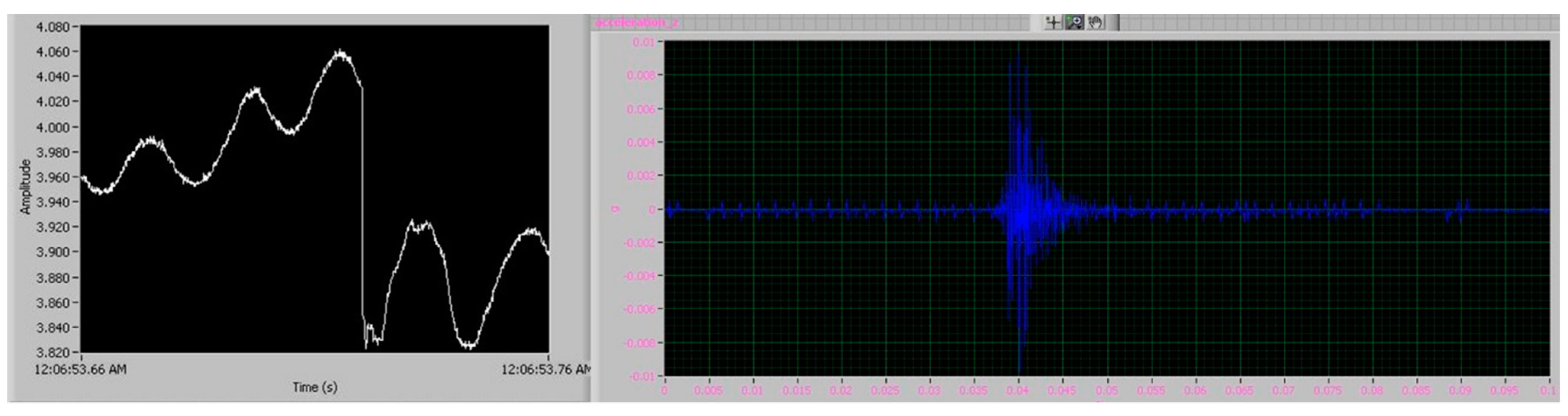
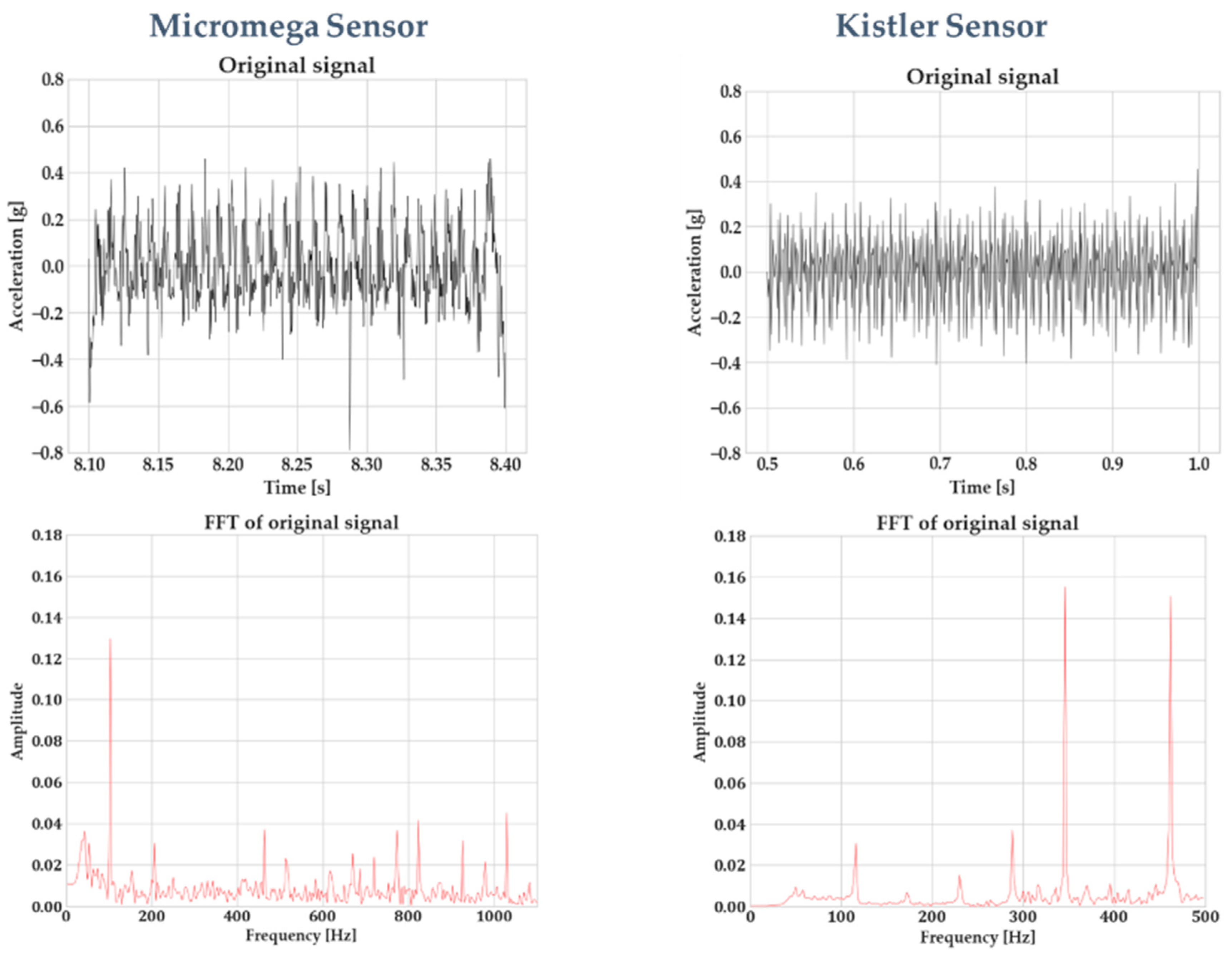
Figure 7 indicates this difference in data quality between the Micromega IAC-CM-U and the Kistler 8762A10 accelerometers. The signals were recorded with the sensors being integrated on the vice, using the same process parameters. It should be noted that the FFT spectrum for the Micromega sensor is larger due to the higher sampling rate that has been employed. Figure 7 highlights this difference in signal quality. Two signals were generated by the Micromega and Kistler sensor, using the same process parameters (1 mm of axial depth of cut, 8 mm of radial engagement, 3100 RPM of spindle speed, and 0.18 mm feed per tooth). Window sampling was performed on the signals, and the window length was tailored for each sensor so that the frequency resolution of the FFT was the same. Due to the different sampling rates for each sensor (5 kHz for the Micromega and 1 kHz for the Kistler, with the second one being limited by the capabilities of the respective National Instruments DAQ), different window lengths need to be employed. Furthermore, the window length was minimized as much as possible because in a real-time chatter-detection application, the cycle time of the whole algorithm execution should be minimized as well. Nevertheless, the evidence of the inferior signal quality of the Micromega sensor is evident. Some numerical noise was introduced in the FFT of the Kistler sensor and was especially evident below 300 Hz due to the window length; however, the overall signal quality can be observed. Compared to the Micromega signal, on the other hand, the noise level at the whole frequency spectrum is evident. This is something for which the following steps of the algorithm compensate.
The use of advanced signal processing algorithms, together with artificial intelligence, has been greatly pursued within the last 5 years in order to detect chatter in milling from vibration signals [6]. However, these algorithms are highly sensitive and prone to fault predictions when signal quality is impaired. In the next sections, we highlight how these algorithms are customized and optimized in order to increase their robustness, make them insensitive to poor signal quality, and continue exploiting their benefits for chatter detection.

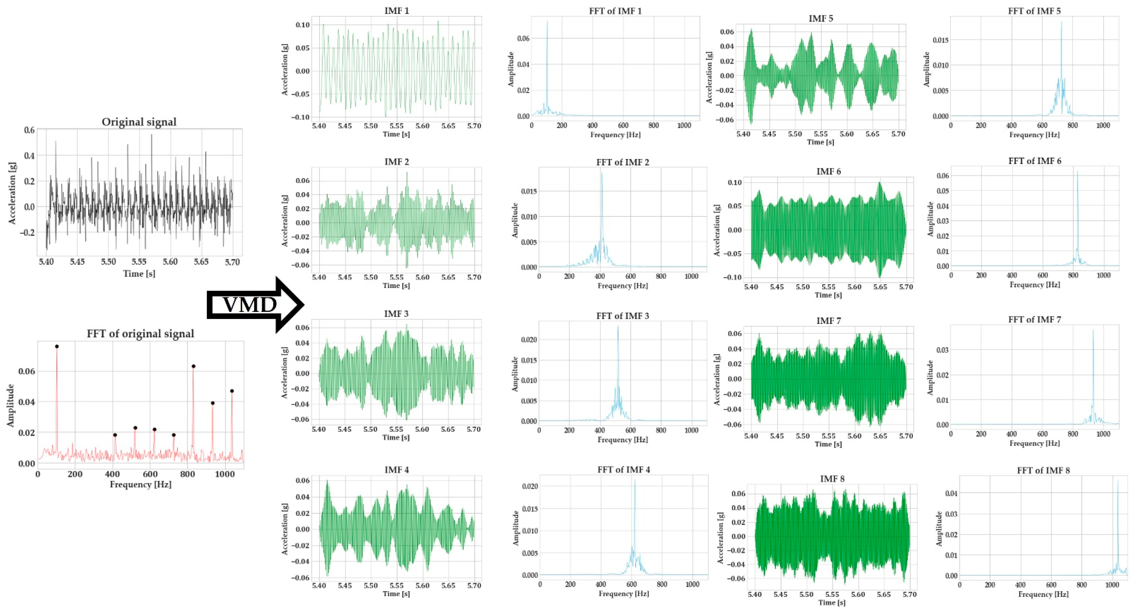
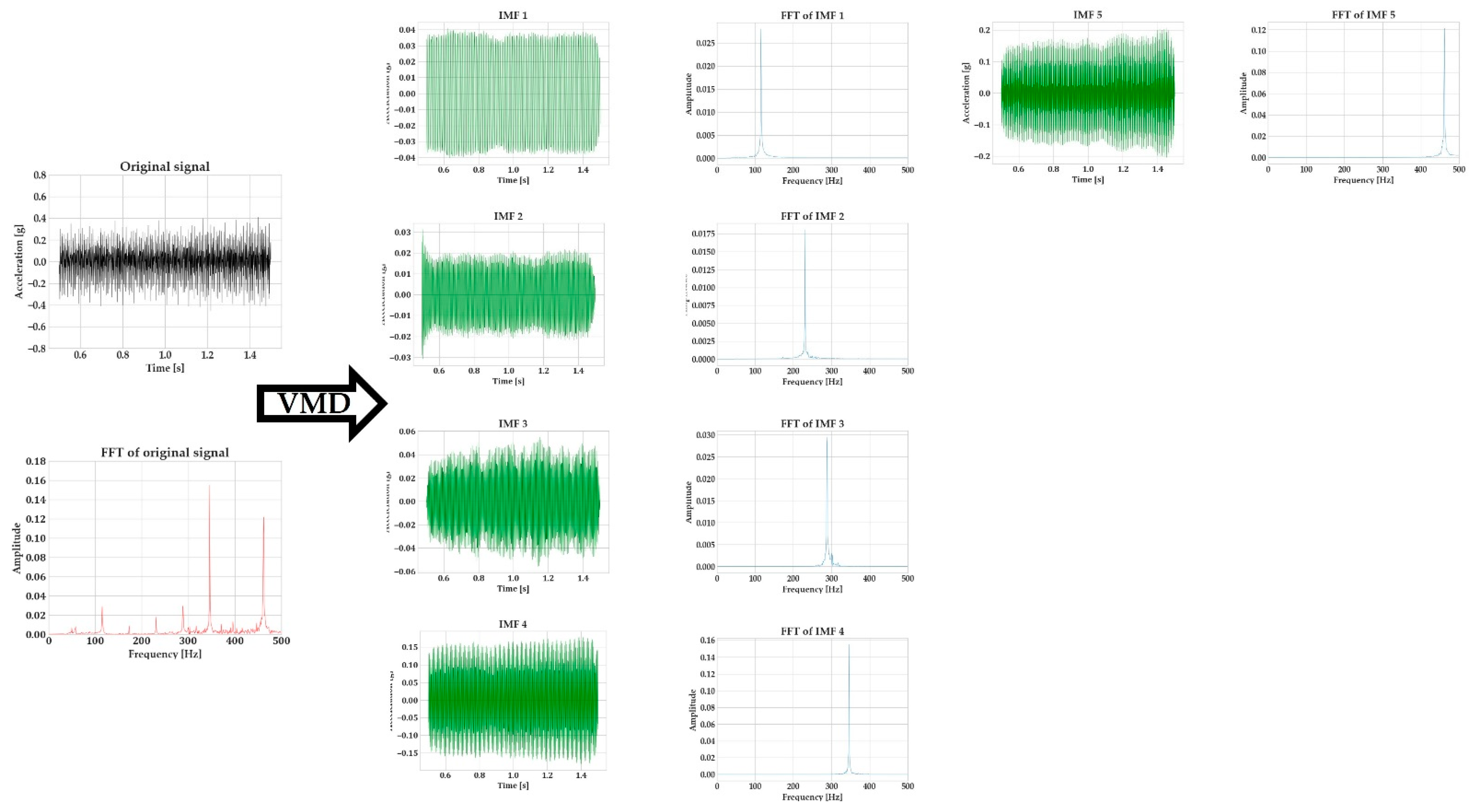
4.1. Vibration Signal Demodulation with Variational Mode Decomposition

Variational mode decomposition (VMD) is an algorithm for signal demodulation developed by Dragomiretskiy and Zosso [27]. VMD is able to decompose a signal into its principal modes ( u k ). These modes are amplitude-modulated–frequency-modulated signals, which are compacted around a center frequency and have specific sparsity properties. The prior sparsity of each mode is its bandwidth in the spectral domain. The superimposition of these modes can recreate the original signal. VMD is a popular algorithm for signal processing in medical applications [28] and has found a use during the last years in the processing of signals generated by machining operations [29,30,31].
In order to assess the bandwidth of each mode, VMD firstly computed the associated analytic signal through the Hilbert transform, with the aim of obtaining a unilateral frequency spectrum. The frequency spectrum of each mode is shifted by mixing it with an exponential tuned to the respective estimated center frequency. The bandwidth of each mode can be estimated through the H1 Gaussian smoothness of the demodulated signal.
Assuming an original time-series signal ( s ( t ) ), its decomposition with VMD into a set of K modes becomes a constrained variational optimization problem, which can be formulated as follows:
min { u k ,   ω k } { k t [ ( δ ( t ) + j π t ) u k ( t ) ] e j ω k t 2 2 } s o   t h a t   k u k = s
where { u k }   : = { u 1 ,   , u K } and { ω k }   : = { ω 1 ,   , ω K } are the modes and their center frequencies, respectively.
The constraint for accurate reconstruction of the signal through the superimposition of the modes is addressed by introducing the quadratic penalty term, also called alpha (α), and the Lagrangian multipliers (λ). The quadratic penalty term ensures reconstruction fidelity, especially when a noisy signal is processed, and the Lagrangian multipliers are a common way of enforcing constraints strictly. This process renders the constrained problem of Equation (1) into an unconstrained one, which can be formulated as follows:
L ( { u k } ,   { ω k } ,   λ )   : = a k t [ ( δ ( t ) + j π t ) u k ( t ) ] e j ω k t 2 2 + s ( t ) k u k ( t ) 2 2 + λ ( t ) ,   s ( t ) k u k ( t )
This optimization problem is solved by the means of alternate direction method of multipliers (ADMM), leading to the following solutions for the modes (Equation (3)) and center frequencies (Equation (4)):
u ^ k n + 1 ( ω ) = s ^ ( ω ) i k u ^ i ( ω ) + λ ^ ( ω ) 2 1 + 2 α ( ω ω k ) 2
ω k n + 1 = 0 ω | u ^ k ( ω ) | 2 d ω 0 | u ^ k ( ω ) | 2 d ω
Considering that the vibration of the system of the milling process (cutting tool-workpiece–milling machine) can be safely assumed as multi-degree of freedom (DoF) oscillator, then by demodulating this vibration signal into several 1-DoF ones, it would be possible to identify the vibration mode that is related to chatter in a milling process. This makes VMD (and signal demodulation algorithms in general) ideal for chatter detection in milling. Nevertheless, their lack of robustness to signal quality (as explained below) is something that should be addressed to make them applicable for a wide range of sensors and a wide range of milling operations [32].
VMD has two key hyperparameters that control the performance of the algorithm: the number of modes (K) that the signal should be decomposed into and the quadratic penalty term (α), which basically controls the bandwidth of each mode. The way that the poor selection of these two hyperparameters affects the decomposition quality is explained in detail in [33]. In any case, it can be easily understood that selection of the wrong number of modes can lead to problems in signal decomposition. Specifically, these are mode mixing (when two modes are combined into a single one—a result of selecting a value for K that is lower than optimal, and the value of alpha allows the creation of wideband modes), loss of information (a mode is fully discarded—a result of selecting a value for K that is lower than optimal, and the value of alpha constrains the algorithm to create narrowband modes), and mode duplication (a single mode is decomposed into two—a result of selecting a value of K that is higher than optimal). It is evident how these three issues could impair chatter-detection performance in a system that is based on VMD for signal decomposition.
Additionally, it is important to have in mind that VMD is basically an optimization algorithm. As with all optimization algorithms, it suffers from the challenge of correct initialization. Specifically for VMD, the critical aspect is the correct initialization of the center frequency. The current available implementations of VMD offer three options of center frequency initialization: (i) all center frequencies are initialized at 0 Hz; (ii) the center frequencies are initialized uniformly, based on the bandwidth of the whole signal; and (iii) the center frequencies are initialized randomly. When the correct value of K is selected, the second initialization option usually produces good results. However, as the signal quality deteriorates, low-energy modes might be mixed with signal noise, leading to unpredictable results.
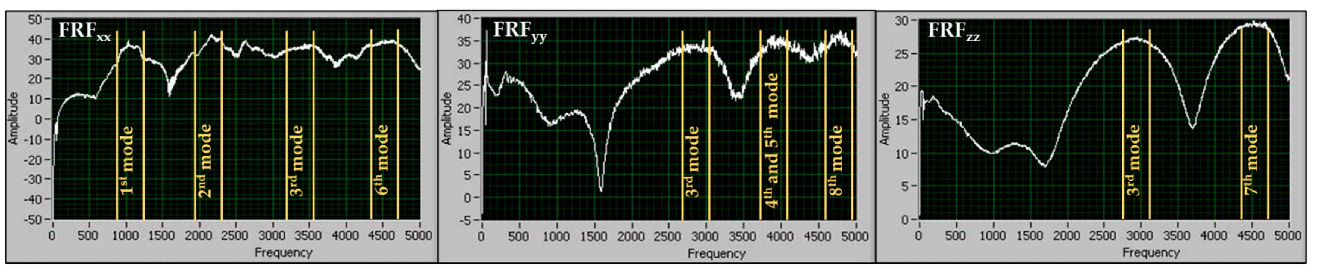
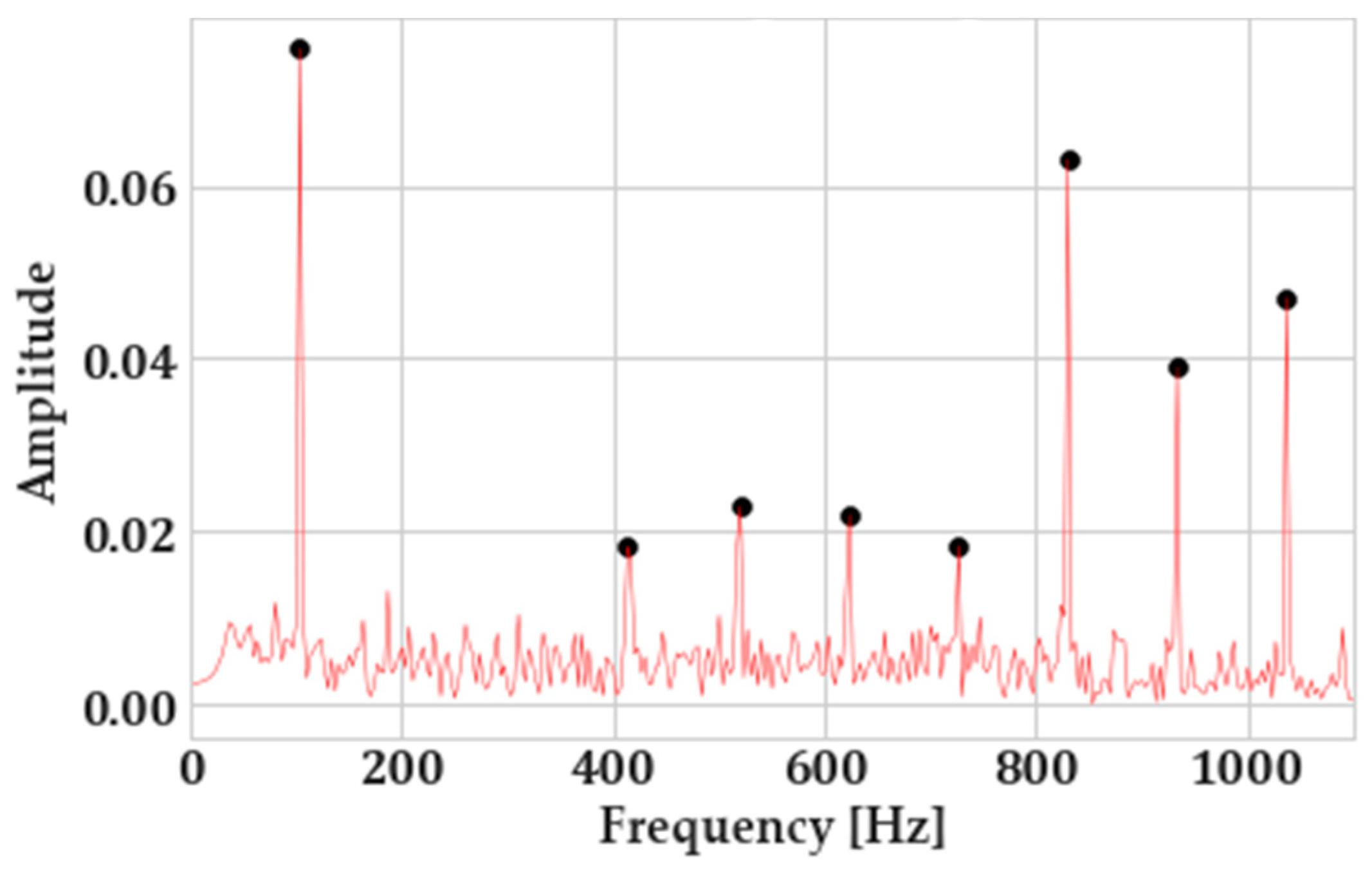
To tackle this and ensure correct initialization of center frequencies and thus the robustness of VMD to signal noise, peak picking is implemented in the fast Fourier-transform (FFT) of the vibration signals. For that, the “find_peaks” algorithm of SciPy (a highly popular package in Python for scientific computing) was utilized. The criterion that has been selected for the identification of a peak was its prominence, as it has been observed to be the most insensitive to the changes in the signal-to-noise ratio (SNR). The prominence of a peak explains how much it stands out due to its intrinsic height and its horizontal location with respect to other peaks. Figure 8 showcases the way peak picking is utilized on the FFTs of the vibration signals.
This procedure ensures that both the number of modes as well as their center frequencies will be correctly identified and ensures correct decomposition. Additionally, it reduces the computational cost of the decomposition process since the algorithm does not need to iterate as many times, as in other initialization options. Finally, regarding the value of alpha (α), a relatively high value of 10,000 was selected through previous experience of the authors with the VMD algorithm [32] to enforce the generation of narrowband modes.

4.2. Feature Engineering towards Chatter Detection

The study of the whole time-series signal or each mode separately (after decomposition) is a computationally heavy process, especially when high sampling rates (over 5kHz) are used in the monitoring system. As such, the extraction of features from the time and frequency domain that can indicate the presence of chatter and the evaluation of few numerical values instead of the whole signal increase the robustness of the system and reduce the cycle time of the chatter-detection operation.
Although the features that are extracted are statistical in nature, it was attempted to attribute a physical meaning to their selection. This entails the explanation of how a physical phenomenon that is exhibited during milling with chatter could be manifested in a statistical property of a time-series signal. This approach of performing feature engineering, considering the physics of the process ensures robustness of the generated features [3], reduces the development and optimization time for the machine learning (ML) algorithm that will be used for chatter detection and facilitates the explainability of the ML predictions. The explainability is an especially important property for the whole system, as it facilitates the evaluation of its performance during the development phase as well as the interaction of its final user (usually a machine operator or process planner without significant experience in ML) during its use phase [34].
The first feature that is calculated is the energy ratio between each individual mode and the whole signal. The energy of a discrete signal, sampled in the time domain, that consists of n samples is formulated as follows:
E d i s c r e t e = i = 1 n | s i | 2
Then, the energy ratio of the k-th mode will be as follows:
E n e r g y   R a t i o = E k E
where E is the energy of the whole signal.
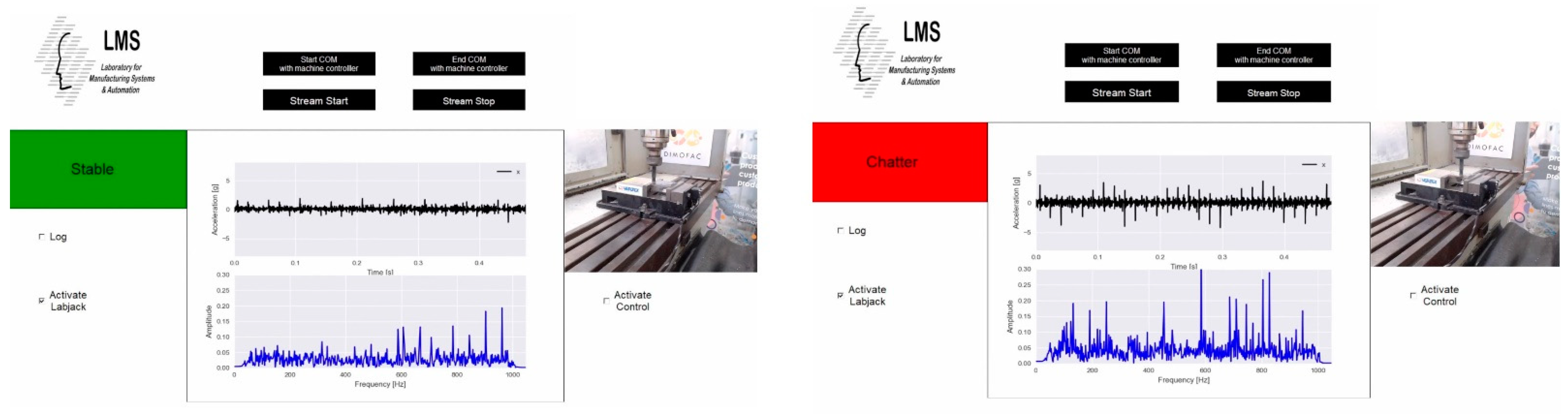
The energy ratio will work as a weighting factor for the calculation of all other signal features, and it is of high importance for the overall robustness of the approach. When stable milling takes place, the signal energy is gathered around the tooth-passing frequency and its harmonics. On the other hand, when the process starts to chatter, an energy shift from the tooth-passing frequency towards the chatter frequency takes place.
As a result, the energy ratio of each mode will capture this transition from harmonic frequencies to a chatter frequency. This supports the robustness of the approach against signal noise, signal disruptions, or other signal artefacts. Although statistically, they might exhibit some similar features with chatter, these signal artefacts will have a low energy contribution to the overall signal. In turn, their weighting with the energy ratio will suppress the features generated from signal artefacts and reduce the false positives (indication of chatter when the process is stable).
The next feature that is examined is the kurtosis of each mode. It is the fourth statistical moment of a signal, and it can describe how transient a signal is. The vibrations during stable machining are periodic and very low (even negative values) for the kurtosis can be expected. On the contrary, chatter (and especially its onset) is a transient phenomenon. As such, the kurtosis is expected to be higher when milling with chatter [32]. The weighted kurtosis of each mode is calculated (using the energy ratio as a weight factor), and the maximum kurtosis of all modes is kept as a signal feature.
The next feature that is considered is the weighted autocorrelation. The cross-correlation of two discrete signals (α and ν) can be formulated as follows:
c k = n a n + k · v n ¯
In Equation (7), the ¯¯ superscript denotes complex conjugation, while k is the value by which signal α is shifted in time with respect to signal ν, also called the lag value. If α and ν are the same signal, then it is possible compute the autocorrelation of this signal with its shifted self. Considering the lag value equal to the spindle rotation period, the autocorrelation of each mode is computed. A stable process is expected to have high autocorrelation (as the phenomenon is fully periodic), while chatter is expected to have low autocorrelation since transient phenomena take place. The weighted autocorrelation (using the energy ratio as a weight factor) of each mode is calculated and stored as a chatter-related metric.
Next, the weighted approximate entropy of each mode is calculated (using the energy ratio as a weight factor). In general, entropy-based algorithms are commonly used in information theory to identify the amount of irregularity in a signal as well as its information content. The approximate entropy can be used to determine the amount of irregularity and unpredictability of fluctuations of a time-series signal. A higher approximate entropy is expected when chatter takes place.
Finally, the spectral entropy of the overall signal is calculated and used as a feature. Spectral entropy is defined to be the Shannon entropy of the power spectral density (PSD) of the signal.
The features mentioned above are extracted from the x-axis and y-axis vibration signals, and a total of eight features is kept to be used as an input for the chatter-detection classifier.

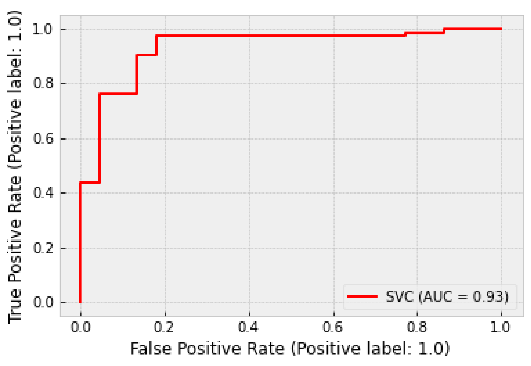
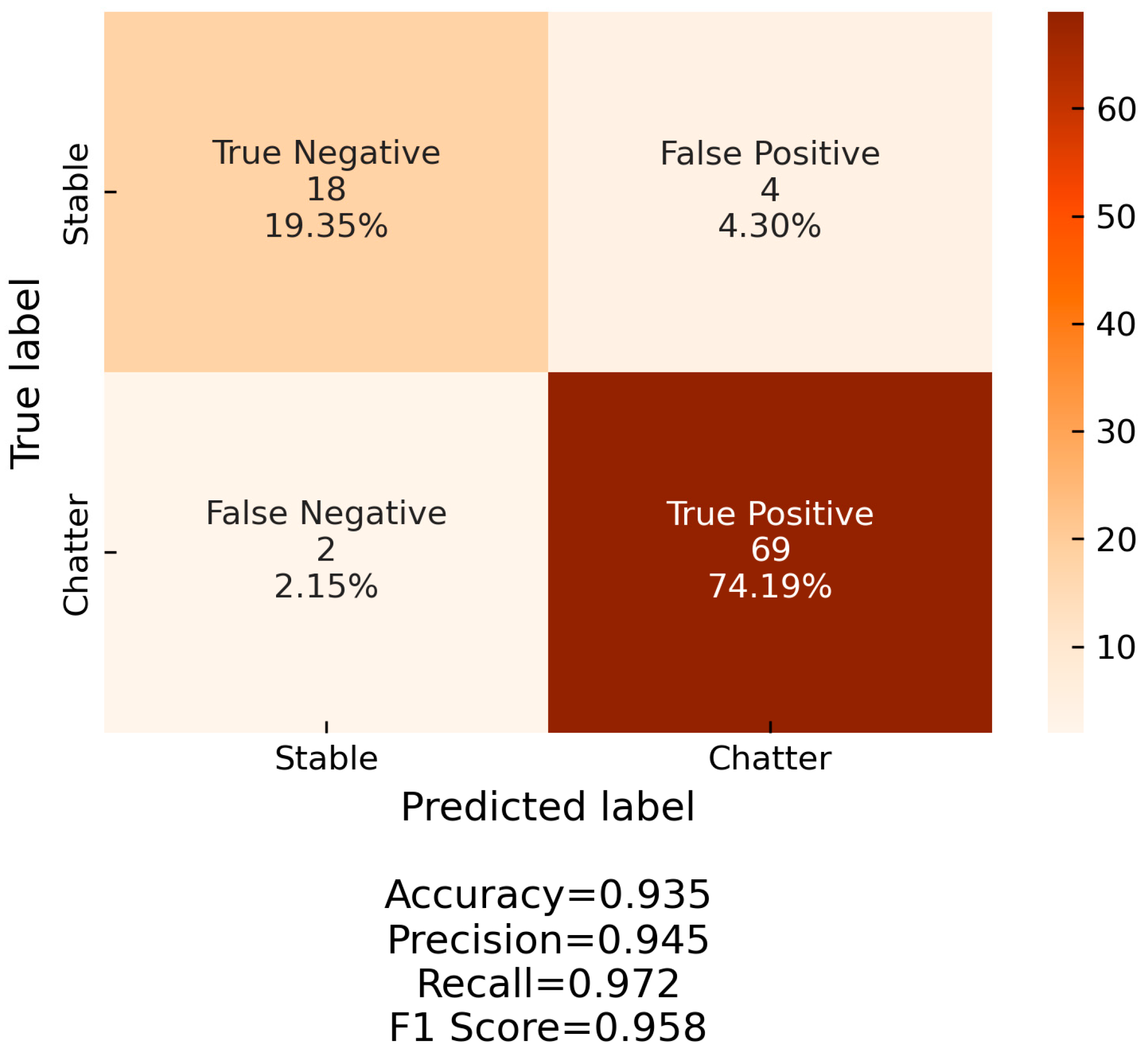
4.3. Chatter Detection

For the detection of chatter, a support vector machine (SVM) classifier was used. SVM is a very popular classification algorithm, which is characterized by a simple structure and training requirements while providing very fast classification speeds. The main goal of SVM is to construct a hyperplane that separates the training dataset with the maximum margin. The hyperplane has one less dimension than the dataset; in this specific case, the dimension of the dataset is the number of input features. For the tuning of SVM, three hyperparameters can be utilized: the kernel function, the magnitude of the slack variable (C), and the parameter gamma (γ). The kernel function is used to transform the dataset and explore the relationships between each data point in higher dimensions and is especially useful for handling non-linear datasets. The slack variable allows for misclassifications to occur during the training of the algorithm in favor of a larger margin between the hyperplane and the two datasets. The slack variable is used to tolerate outliers in the hyperplane construction. Finally, the parameter gamma determines the maximum distance a data point can have from the hyperplane in order to influence its construction.
For this specific application, a radial basis function (RBF) kernel function was selected. Additionally, an exhaustive grid search was performed to tune the C and γ hyperparameters. A 5-fold cross-validation scheme was employed, testing 1000 different values for each variable, evenly spaced in a logarithmic scale. The range for C was [0.01, 100000] and for γ the range was [0.00000001, 100]. Based on this optimization, the values of C = 1 and γ = 10 were selected. The SVM algorithm was implemented in Python using the scikit-learn package [35].

4.4. Training Dataset

For training and testing of the SVM-based chatter-detection system, the dataset presented in [32] was utilized. The workpiece materials were aluminum 7075-T6 and 1.7227 low-alloy steel. The cutting tool was a Sandvik R390-010A10-07L indexable end mill with Sandvik 390R-070202M-PM 4340 inserts (Table 5). The tool overhang was at 60 mm, and the tool run-out was measured at 0.01 mm using a dial indicator. A total of 40 milling experiments were conducted with different sets of process parameters. Their ranges are presented in Table 6.
By performing window sampling on the datasets with a window length of 500 samples, a total of 347 data points was collected, with each data point having the eight features that were described in Section 4.2. The dataset was split at 70% for the training phase and 30% for the testing phase.

4.5. Software Implementation

A bespoke Python application was developed to facilitate data streaming and real-time monitoring and characterization of the stability of the milling process specifically as follows:
  • A stream was opened with the Labjack T7-Pro DAQ, which feeds real-time acceleration data at a 5kHz sampling rate to the chatter-detection algorithms. Parameters such as sensor calibration, sampling rate, length of the sampling window, etc., can be configured by the user of the system through a configuration file;
  • The acceleration data were first filtered during acquisition by the built-in RMS filter of Labjack T7-Pro DAQ. Then, the Python script imposed a digital, Butterworth bandpass filter on the vibration signal with the passing-frequencies range being 40–1000 Hz;
  • The acceleration data were fed to the chatter-detection algorithms, and the milling stability was evaluated,
  • The acceleration data, the fast Fourier-transform (FFT) of the data, and the chatter status were displayed in a user interface that was developed for this application. This user interface provides additional functionalities, such as start and stop of the stream, start and stop of communication with the machine controller, etc. The user interface is presented in Figure 9.

5. Results and Discussion

Figure 10 showcases the decomposition of a vibration signal generated by the sensor-integrated milling vice, while Figure 11 presents the respective results for the Kistler sensor, providing an overview on the way VMD handles the different signal-to-noise ratios between the two signals. The specific process parameters corresponding to this signal are 8mm of radial engagement, 1 mm of axial depth of cut, 3100 RPM (corresponding to a cutting speed of 155 m/min), and a feed per tooth of 0.18 mm. As it can be observed, the peak-picking algorithm captures the FFT peaks successfully and enables the correct initialization of VMD since the center frequencies of the decomposed modes match exactly the FFT of the original signal.
By applying the aforementioned methodology, it was possible to achieve a very high classification performance. Figure 12 and Figure 13 showcase the receiver operating curve (ROC) and the confusion matrix of the SVM classifier. A very high AUC score is observed. Additionally, it is very important that the false negatives (i.e., prediction of a stable process when the process chatters) are minimal. This ensures the robustness of the algorithm and the quick reaction to chatter onset.

6. Conclusions

The goal of this paper is to propose a low-cost, non-invasive solution for the sensorization of tooling in milling processes that is suitable for industrial implementation. Based on the results that were gathered from this study, the following conclusions can be drawn:
  • The simulation of the dynamic behavior of the system where the sensor will be integrated is crucial for the correct sensor-integration point selection;
  • The experimental modal analysis with the impact hammer testing validated the simulation results;
  • The use of advanced signal processing algorithms can mitigate the effect of lower data quality due to reduced sensor cost by comparing the results generated by the approach of this paper to the results of [7]. As such, it can enable the generation of a high-performance chatter-detection system, without the cost penalty of existing solutions;
  • The use of peak picking on the vibration signal FFTs can solve the initialization and hyperparameter selection problem for VMD, leading to an adaptive and robust decomposition of the signal.
Future work should include the integration of a control system that closes the loop with the machine tool and adapts the process parameters (feed rate and spindle speed) in real time to suppress chatter.

Author Contributions

Conceptualization, P.S.; methodology, T.S. and D.M.; software, T.S.; validation, T.S., H.B. and P.S.; formal analysis, H.B.; investigation, T.S., D.M. and C.P.; resources, P.S.; data curation, C.P.; writing—original draft preparation, T.S., D.M. and C.P.; writing—review and editing, H.B. and P.S.; visualization, H.B. and D.M.; supervision, P.S.; project administration, P.S.; funding acquisition, P.S. All authors have read and agreed to the published version of the manuscript.

Funding

This research received no external funding.

Data Availability Statement

Not applicable.

Acknowledgments

This research has been partially supported by the H2020 EU Project DIMOFAC—Digital Intelligent MOdular FACtories.

Conflicts of Interest

The authors declare no conflict of interest.

References

  1. Mourtzis, D. Machine Tool 4.0 in the Era of Digital Manufacturing. In Proceedings of the 32nd European Modeling & Simulation Symposium (EMSS 2020), Online, 16–18 September 2020; pp. 416–429. [Google Scholar] [CrossRef]
  2. Liu, C.; Xu, C. Cyber-physical Machine Tool—The Era of Machine Tool 4.0. Procedia CIRP 2017, 63, 70–75. [Google Scholar] [CrossRef]
  3. Stavropoulos, P. Digitization of Manufacturing Processes: From Sensing to Twining. Technologies 2022, 10, 98. [Google Scholar] [CrossRef]
  4. Möhring, H.-C.; Wiederkehr, P.; Erkorkmaz, K.; Kakinuma, Y. Self-optimizing machining systems. CIRP Ann. 2020, 69, 740–763. [Google Scholar] [CrossRef]
  5. Munoa, J.; Beudaert, X.; Dombovari, Z.; Altintas, Y.; Budak, E.; Brecher, C.; Stepan, G. Chatter suppression techniques in metal cutting. CIRP Ann. 2016, 65, 785–808. [Google Scholar] [CrossRef]
  6. Teti, T.; Mourtzis, D.; D’Addona, D.M.; Caggiano, A. Process monitoring of machining. CIRP Ann. 2022, 71, 529–552. [Google Scholar] [CrossRef]
  7. Stavropoulos, P.; Manitaras, D.; Papaioannou, C.; Souflas, T.; Bikas, H. Development of a Sensor Integrated Machining Vice Towards a Non-invasive Milling Monitoring System. In Flexible Automation and Intelligent Manufacturing: The Human-Data-Technology Nexus. FAIM 2022; Kim, K.Y., Monplaisir, L., Rickli, J., Eds.; Lecture Notes in Mechanical Engineering; Springer: Cham, Switzerland, 2023; pp. 29–37. [Google Scholar] [CrossRef]
  8. Bleicher, F.; Schörghofer, P.; Habersohn, C. In-process control with a sensory tool holder to avoid chatter. J. Mach. Eng. 2018, 18, 16–27. [Google Scholar] [CrossRef]
  9. Xie, Z.; Lu, Y.; Chen, X. A multi-sensor integrated smart tool holder for cutting process monitoring. Int. J. Adv. Manuf. Technol. 2020, 100, 853–864. [Google Scholar] [CrossRef]
  10. Rizal, M.; Ghani, J.A.; Nuawi, M.Z.; Che-Haron, C.H. Development and testing of an integrated rotating dynamometer on tool holder for milling process. Mech. Syst. Signal Process 2015, 52–53, 559–576. [Google Scholar] [CrossRef]
  11. Matsuda, R.; Shindou, M.; Hirogaki, T.; Aoyama, E. Monitoring of Rotational Vibration in Tap and Endmill Processes with a Wireless Multifunctional Tool Holder System. Int. J. Autom. Technol. 2018, 12, 876–882. [Google Scholar] [CrossRef]
  12. Zhou, C.; Guo, K.; Sun, J. An integrated wireless vibration sensing tool holder for milling tool condition monitoring with singularity analysis. Measurement 2021, 174, 109038. [Google Scholar] [CrossRef]
  13. Promicron Spike. Available online: https://www.pro-micron.de/spike/?lang=en (accessed on 16 November 2022).
  14. Schunk iTENDO. Available online: https://schunk.com/hu/en/tools/toolholder-quickfinder/itendo2/c/PGR_6468 (accessed on 16 November 2022).
  15. Totis, G.; Wirtz, G.; Sortino, M.; Veselovac, D.; Kuljanic, E.; Klocke, F. Development of a dynamometer for measuring individual cutting edge forces in face milling. Mech. Syst. Signal Process. 2010, 24, 1844–1857. [Google Scholar] [CrossRef]
  16. Luo, M.; Luo, H.; Axinte, D.; Liu, D.; Mei, J.; Liao, Z. A wireless instrumented milling cutter system with embedded PVDF sensors. Mech. Syst. Signal Process. 2018, 110, 556–568. [Google Scholar] [CrossRef] [Green Version]
  17. Drossel, W.-G.; Gebhardt, S.; Bucht, A.; Kranz, B.; Schneider, J.; Ettrichrätz, M. Performance of a new piezoceramic thick film sensor for measurement and control of cutting forces during milling. CIRP Ann. 2018, 67, 45–48. [Google Scholar] [CrossRef]
  18. Cen, L.; Melkote, S.N.; Castle, J.; Appelman, H. A Wireless Force-Sensing and Model-Based Approach for Enhancement of Machining Accuracy in Robotic Milling. IEEE ASME Trans. Mechatron. 2016, 21, 2227–2235. [Google Scholar] [CrossRef]
  19. Campidelli, A.F.V.; Lima, H.V.; Abrão, A.M.; Maia, A.A.T. Development of a wireless system for milling temperature monitoring. Int. J. Adv. Manuf. Technol. 2019, 104, 1551–1560. [Google Scholar] [CrossRef]
  20. Ostasevicius, V.; Karpavicius, P.; Jurenas, V.; Cepenas, M.; Cesnavicius, R.; Eidukynas, D. Development of universal wireless sensor node for tool condition monitoring in milling. Int. J. Adv. Manuf. Technol. 2020, 110, 1015–1025. [Google Scholar] [CrossRef]
  21. Liu, D.; Hu, Y.; Zhang, D.; Luo, H. Milling force monitoring with thin-film sensors integrated into fixtures. Int. J. Adv. Manuf. Technol. 2019, 103, 1519–1527. [Google Scholar] [CrossRef]
  22. Rezvani, S.; Kim, C.-J.; Park, S.S.; Lee, J. Simultaneous Clamping and Cutting Force Measurements with Built-In Sensors. Sensors 2020, 20, 3736. [Google Scholar] [CrossRef]
  23. Denkena, B.; Dahlmann, D.; Boujnah, H. Sensory Workpieces for Process Monitoring—An Approach. Proc. Technol. 2016, 26, 129–135. [Google Scholar] [CrossRef] [Green Version]
  24. Brecher, C.; Eckel, H.-M.; Motschke, T.; Fey, M.; Epple, A. Estimation of the virtual workpiece quality by the use of a spindle-integrated process force measurement. CIRP Ann. 2019, 68, 381–384. [Google Scholar] [CrossRef]
  25. Hoang, D.T.; Nguyen, N.-T.; Tran, Q.D.; Van Nguyen, T. Cutting Forces and Surface Roughness in Face-Milling of SKD61 Hard Steel. J. Mech. Eng. 2019, 65, 375–385. [Google Scholar] [CrossRef]
  26. Stavropoulos, P.; Papacharalampopoulos, A.; Souflas, T. Indirect online tool wear monitoring and model-based identification of process-related signal. Adv. Mech. Eng. 2020, 12, 1687814020919209. [Google Scholar] [CrossRef]
  27. Dragomiretskiy, K.; Zosso, D. Variational Mode Decomposition. IEEE Trans. Signal Process. 2014, 62, 531–544. [Google Scholar] [CrossRef]
  28. Gavas, R.; Jaiswal, D.; Chatterjee, D. Multivariate Variational Mode Decomposition based approach for Blink Removal from EEG Signal. In Proceedings of the 2020 IEEE International Conference on Pervasive Computing and Communications Workshops (PerCom Workshops), Austin, TX, USA, 23–27 March 2020; pp. 1–6. [Google Scholar] [CrossRef]
  29. Peng, D.; Li, H.; Ou, J.; Wang, Z. Milling chatter identification by optimized variational mode decomposition and fuzzy entropy. Int. J. Adv. Manuf. Technol. 2022, 121, 6111–6124. [Google Scholar] [CrossRef]
  30. Liu, X.; Wang, Z.; Li, M.; Yue, C.; Liang, S.Y.; Wang, L. Feature extraction of milling chatter based on optimized variational mode decomposition and multi-scale permutation entropy. Int. J. Adv. Manuf. Technol. 2021, 114, 2849–2862. [Google Scholar] [CrossRef]
  31. Wang, R.; Niu, J.; Sun, Y. Chatter identification in thin-wall milling using an adaptive variational mode decomposition method combined with the decision tree model. Proc. Inst. Mech. Eng. B J. Eng. Manuf. 2022, 236, 51–63. [Google Scholar] [CrossRef]
  32. Stavropoulos, P.; Souflas, T.; Papaioannou, C.; Bikas, H.; Mourtzis, D. An adaptive, artificial intelligence-based chatter detection method for milling operations. Int. J. Adv. Manuf. Technol. 2022. [Google Scholar] [CrossRef]
  33. Souflas, A. Generation of Manufacturing Process Knowledge for Process Optimization: A Case Study on Milling. Diploma Thesis, University of Patras, Patras, Greece, 2021. [Google Scholar]
  34. Senoner, J.; Netland, T.; Feuerriegel, S. Using explainable artificial intelligence to improve process quality: Evidence from semiconductor manufacturing. Manag. Sci. 2021, 68, 5704–5723. [Google Scholar] [CrossRef]
  35. Pedregosa, F.; Varoquaux, G.; Gramfort, A.; Michel, V.; Thirion, B.; Grisel, O.; Blondel, M.; Prettenhofer, P.; Weiss, R.; Dubourg, V.; et al. Scikit-learn: Machine Learning in Python. J. Mac. Learn. Res. 2011, 12, 2825–2830. [Google Scholar]
Figure 1. Sensor integration with a modified steady jaw—Option 1 (a); sensor integration on the back of the vice—Option 2 (b).
Machines 11 00052 g001
Figure 2. Experimental setup for impact hammer testing. (a) Setup (b) Setup-Vice (c) Impact Testing (d) Impact testing, 2nd photograph.
Machines 11 00052 g002
Figure 3. Impact hammer (left) and accelerometer (right) signals during impact testing for determination of FRFzz.
Machines 11 00052 g003
Figure 4. Experimentally obtained frequency response functions [7].
Machines 11 00052 g004
Figure 5. Vibration amplitudes at the sensor-integration point [7].
Machines 11 00052 g005
Figure 6. Overview of the overall monitoring system.
Machines 11 00052 g006
Figure 7. Difference in signal quality between Micromega and Kistler sensor.
Machines 11 00052 g007
Figure 8. Mode identification from the FFT of the vibration signal.
Machines 11 00052 g008
Figure 9. Snippet from the user interface of the chatter-detection system.
Machines 11 00052 g009
Figure 10. Decomposition of the milling vibration signal generated by the Micromega sensor with VMD.
Machines 11 00052 g010
Figure 11. Decomposition of the milling vibration signal generated by the Kistler sensor with VMD.
Machines 11 00052 g011
Figure 12. ROC curve of chatter detector.
Machines 11 00052 g012
Figure 13. Confusion matrix of chatter detector.
Machines 11 00052 g013
Table 1. Technical specifications of Micromega accelerometer [7].
SpecificationValue
Acceleration range (g)±25
Acceleration limit (g)100
Sensitivity, ±2…5% (mV/g)80
Frequency response (kHz)0 … 10
Amplitude non-linearity (%FS)±0.5 … 1.5
Sensing elementSeismic mass
Mounting3.2 mm diameter holes
Case materialStainless steel casing and cable gland A4/AISI316 grade
Table 2. Results from the modal analysis in ANSYS software [7].
Mode #Frequency (Hz)Effective Mass Ratio (%)
X-AxisY-AxisZ-Axis
1117134.760.000.00
2215759.1896.940.00
333012.480.000.00
438500.170.000.00
539370.000.000.76
647140.050.000.00
748320.000.082.94
849620.000.010.34
Table 3. Technical specifications of the Kistler impact hammer.
SpecificationValue
Force range (N)0 … 5000
Maximum force (N)12,500
Sensitivity (mV/N)1
Resonant frequency (kHz)27
Time constant (s)500
Rigidity (Ν/μm)800
Head diameter (mm)23.11
Head weight (kg)0.25
Table 4. Technical specifications of the Kistler accelerometer [7].
SpecificationValue
Acceleration range (g)±10
Acceleration limit (g)±16
Sensitivity, ±5% (mV/g)500
Resonant frequency (kHz)30
Frequency response, ±5% (kHz)0.5 … 6000
Amplitude non-linearity (%FSO)±1
Time constant (s)1
Sensing elementCeramic shear
Table 5. Cutting tool specifications.
SpecificationValue
Cutting diameter (mm)16
Depth of cut maximum (mm)10
Cutting edge angle (o)90
Helix angle (o)0
Radial rake angle (o)−10.596
Cutting edge number2
Insert corner radius (mm)0.4
Insert materialTungsten carbide
Table 6. Table of experiments.
SpecificationValue (Aluminum)Value (Steel)
Spindle speed (RPM)1200–36002220–3380
Cutting speed (m/min)60–180110–170
Radial depth of cut (mm)816
Axial depth of cut (mm)0.5–4.50.5–5
Feed per tooth (mm)0.06–0.420.07–0.14
Disclaimer/Publisher’s Note: The statements, opinions and data contained in all publications are solely those of the individual author(s) and contributor(s) and not of MDPI and/or the editor(s). MDPI and/or the editor(s) disclaim responsibility for any injury to people or property resulting from any ideas, methods, instructions or products referred to in the content.

