Article

Path Planning of Autonomous 3-D Scanning and Reconstruction for Robotic Multi-Model Perception System

1
College of Artificial Intelligence, Nankai University, Tianjin 300350, China
2
Laboratory of Science and Technology on Integrated Logistics Support, National University of Defense Technology, Changsha 410073, China
3
Institute of Intelligence Technology and Robotic Systems, Shenzhen Research Institute of Nankai University, Shenzhen 518083, China
4
Industrial Robot Application of Fujian University Engineering Research Center, Minjiang University, Fuzhou 350108, China
5
IStrong Technology Co., Ltd., Fuzhou 350108, China
*
Author to whom correspondence should be addressed.
Machines 2023, 11(1), 26; https://doi.org/10.3390/machines11010026
Submission received: 29 November 2022 / Revised: 20 December 2022 / Accepted: 23 December 2022 / Published: 26 December 2022
(This article belongs to the Special Issue Motion Planning and Advanced Control for Robotics)

Abstract

:
Applying a three-dimensional (3-D) reconstruction from mapping-oriented offline modeling to intelligent agent-oriented environment understanding and real-world environment construction oriented to agent autonomous behavior has important research and application value. Using a scanner to scan objects is a common way to obtain a 3-D model. However, the existing scanning methods rely heavily on manual work, fail to meet efficiency requirements, and are not sufficiently compatible with scanning objects of different sizes. In this article, we propose a creative visual coverage path planning approach for the robotic multi-model perception system (RMMP) in a 3-D environment under photogrammetric constraints. To realize the 3-D scanning of real scenes automatically, we designed a new robotic multi-model perception system. To reduce the influence of image distortion and resolution loss in 3-D reconstruction, we set scanner-to-scene projective geometric constraints. To optimize the scanning efficiency, we proposed a novel path planning method under photogrammetric and kinematics constraints. Under the RMMP system, a constraints-satisfied coverage path could be generated, and the 3-D reconstruction from the images collected along the way was carried out. In this way, the autonomous planning of the pose of the end scanner in scanning tasks was effectively solved. Experimental results show that the RMMP-based 3-D visual coverage method can improve the efficiency and quality in 3-D reconstruction.

1. Introduction

1.1. Background and Significance

With the revolutionary development of manufacturing, computer vision, virtual reality, human–computer interaction, and other fields, the demand for 3-D models is increasing. They are widely used in industrial manufacturing [1,2], construction engineering [3], film and television entertainment [4], driverless [5], cultural relics restoration [6,7], medical and health care [8], etc. There is an increasing demand [9,10] for 3-D reconstruction for objects or scenes of different sizes, such as the reconstruction of desktop decorations at the scale of cm [11,12,13], reconstruction of car and airplane surfaces that are as large as meters [14,15,16], and reconstruction of outdoor natural scenes [17]. In addition, the requirements for the degree of automation and efficiency of the reconstruction process [18,19] are getting higher and higher. It is of great significance for industrial manufacturing and production life to realize the 3-D reconstruction of different-sized objects or scenes and 3-D scanning with a high automation and efficiency.
Currently, 3-D scanning solutions for different-sized objects have been proposed in succession. In order to scan small-sized objects, Hall-Holt O et al. [20] used a combined approach of a camera and projector to achieve scanning within an operating range of 10 cm, which guaranteed an image acquisition frequency of 60 Hz and a 100 μm accuracy. Percoco, G et al. [21] used the digital close-range photogrammetry (DCRP) method for scanning millimeter-scale objects. In order to scan larger-than-millimeter-scale objects, Li W et al. [22] designed a rotating binocular vision measurement system (RBVMS), which uses two cameras and two warp meters as a two-dimensional rotating platform. It measures 300 mm and 600 mm targets with an accuracy of approximately 0.014 mm and 0.027 mm. Straub J et al. [23] built a 3-D scan space with eight prismatic regions and used 50 cameras for data acquisition. Zeraatkar M et al. [24] used 100 cameras to build a cylindrical scanning space for a 3-D scanning system targeting person. Yin S et al. [25] and Du H et al. [26] designed a method for an industrial robotic arm to hold the scanner, and the method was combined with the use of a laser range finder for end positioning. In order to scan large-sized objects, Zhen W et al. [27,28] used a binocular plus LiDAR acquisition scheme for the 3-D scanning of large civil engineering designs, such as bridges and buildings.
The above scanners all use fixed schemes or handheld methods, which do not have autonomous motion exploration capabilities and are not suitable for large-range and long-time 3-D scanning tasks. With the development of robotics, an increasing amount of research has been conducted to increase the scanner motion capability in order to improve the efficiency and automation of the scanning process. Shi J et al. [29] designed multiple-vision systems mounted on an L-shaped robotic arm. The systems slide on a rail and use a laser rangefinder to acquire the distance between one end of the rail and robotic arm to facilitate 3-D reconstruction. Since the camera only acquires image data in an overhead manner, the reconstruction effect is rational for the top of the object but poor for the side of the object. Wang J et al. [30,31] proposed a measurement solution based on a mobile robot and a 3-D reconstruction method based on multi-view point cloud alignment. The mobile optical scanning robot system for large and complex components was also investigated for positioning using ground position coded markers. Although the method has a good error accuracy, it places new requirements on the ground coding and positioning process, which increases the task difficulty. Zhou Z et al. [32,33] proposed a better measurement, combining a global laser tracker, local scanning system, and industrial robot with a mobile platform. The measurement based on a priori knowledge establishes the correlation constraints between local and global calibrations, improving the measurement accuracy.
To improve the automation of 3-D scanning, it is necessary to plan the path for the robot, making it maximize the information gained about the objects or scenes. Path planning is widely used in robotic systems with mobility functions. For example, using distributed smart cameras in low-cost autonomous transport systems for adapting to future requirements of a smart factory [34]. Solutions toward path planning problems include sampling-based methods, frontier-based methods, or a combination of both. In sampling-based methods, ref. [35] presented a new RRT*-inspired online informative path planning algorithm by expanding a single tree of candidate trajectories and rewiring nodes to maintain the tree and refine intermediate paths. Furthermore, ref. [36] proposed a next-best-view planner that can perform full exploration and user-oriented exploration with an inspection of the regions of interest using a mobile manipulator robot. In frontier-based methods, ref. [37] proposed an exploration planning framework that is a reformulation of information gain as a differentiable function. This allows us to simultaneously optimize information gain with other differentiable quality measures. In the method of combination, ref. [38] achieved a fast and efficient exploration performance with tight integration between the octree-based occupancy mapping approach, frontier extraction, and motion planning.
To address the shortcomings of generic path planning methods in 3-D scanning tasks, a new multi-model perception robotic system was designed in the manuscript. Furthermore, a novel path planning method based on the system is proposed in this paper. The robotic system includes four submodules: a mechanical module, driving module, control module, and self-made sensing module. Therefore, it can scan objects of different sizes automatically. In addition, the path planning method using photogrammetric and kinematic constraints improves the level of 3-D scanning automation. The method proposed in this paper is applicable to 3-D scanning and reconstruction tasks and can satisfy 3-D scanning and reconstruction for outdoor natural scenes, indoor environments, or objects; for example, the 3-D scanning and reconstruction of workpieces in industrial manufacturing. The research content of this paper is shown in Figure 1.

1.2. Aims and Contributions

This paper mainly focuses on the path planning of autonomous 3-D scanning and reconstruction for the robotic multi-model perception system. The main contributions of this work are as follows:
(1)
This paper proposes a novel path planning approach for 3-D visual coverage scanning. By defining a set of practical photogrammetric constraints, the quality of the images collected along the way of the robotic system is effectively improved. Different from the existing path planning algorithms—either frontier-based methods, sampling-based methods, or a combination of both—we planned the path based on the shape of the objects. The proposed strategy can obtain dynamic feasible paths based on the true shapes of the scanning objects;
(2)
This paper defines two new photogrammetric constraints for image acquisition based on the shape of scenes or objects. In order to obtain an accurate model of the ROI, the images obtained from the cameras integrated into the scanner should satisfy the equidistant and frontal constraints. In this way, the problems of image deformation and resolution loss caused by the shape change of the scenes or objects to be reconstructed can be resolved;
(3)
This paper proposes a novel design of a scanner and robotic system for coverage scanning tasks. Firstly, we designed a scanner equipped with LiDAR, Realsense, and multiple cameras. Secondly, we used a mobile platform and robotic arm to ensure the robotic system’s ability to move in 3-D space. Finally, the designed scanner was mounted at the end of the robotic arm to form the scanning robotic system, which can significantly improve both the quality of photography and the efficiency of scanning.

2. Problem Formulation

2.1. Assumptions

Consider a scenario where a 3-D ROI needs to be fully covered by images obtained from cameras mounted on the scanner. The moving of the scanner is subjected to photogrammetric and kinematics constraints based on the preliminary work of our subject group [39]. We make the following assumptions:
(1)
The ground in the three-dimensional space where the robotic system is located is required to be flat without potholes or bulges, so as to achieve smooth robotic system movement;
(2)
The LiDAR, Realsense, and multiple cameras on the scanner should have been pre-calibrated. In addition, the parameters of the cameras and images, such as the camera field of view (FOV) and image resolution, should have been known in advance. In addition, the scanner and the end of the robotic arm should have been pre-calibrated.
(3)
Individual images are used or multiple images are seen as a composite individual image for further theoretical analysis, for the purpose of path planning.

2.2. Definition of Photogrammetric Constraints and Problem Statement

We aimed to capture images of D with high quality, and to further obtain an accurate 3-D model. D is the side of scanned objects. Therefore, some constraints should be considered when the shutter of the camera is triggered.
Let X represent the discrete scanner waypoints: X = [ x y z γ β α ] T X R 6 . g 1 ( X ) is a set of constraint functions that satisfy the following photogrammetric conditions at a specific waypoint, as shown in Figure 2.
(1)
Equidistant: In order to maintain a consistent image resolution, the position of each waypoint X should keep a constant offset distance h from the fitted plane with a bounded position error ϵ 1 ;
(2)
Frontal: For each waypoint X , the orientation of the camera ( [ γ β α ] ) is perpendicular to the fitted plane to capture an orthophotograph with a bounded angle error ϵ 2 ;
(3)
Overlap: In the 3-D reconstruction application, the images should be acquired with a horizontal overlapping rate σ 0 and vertical overlapping rate σ 1 .
In this paper, the equidistant h was set by evaluating the expected resolution when given the distance and the intrinsic parameters of the camera, which is consistent with [40,41]. The normal vector of the fitted plane was used to set the frontal constraint. According to [42], the overlapping rates σ 0 and σ 1 were determined.
To cover the 3-D space D , a robotic system was involved, which was equipped with a scanner for multi-model perception. As shown in Figure 2, the robotic system follows a path that contains all of the waypoints generated under photogrammetric and kinematic constraints, and ultimately achieves the coverage scanning task.
For the robot path planning, we parameterized the obtained path as X = [ X 1 X 2 X n ] , where X was set to fully cover D . The objective of the mission was to minimize the path length L ( X ) under the constraints g ( X ) . The exact formulas of the objectives and constraints will be given in the following sections.

2.3. Next View Planner

The next view planner is one of the robotic system functions, and determines the ideal scanning position and attitude of the 3-D scanner at the next moment according to the shape change of the scenes or objects. The planner needs to input LiDAR or Realsense point cloud data. LiDAR covers medium and long-range 3-D scanning, and Realsense covers 0.2 m∼10 m 3-D scene scanning. Since the laser point cloud acquires 360-degree point cloud data, the next view planner only needs a certain angle in front of the scanner, so it is considered to intercept the laser point cloud with a slightly larger angle than the image resolution. After data preprocessing, plane fitting, photogrammetric constraints, and other processing, the ideal scanning pose of the 3-D scanner in the robotic system at the next moment can be calculated. The whole calculation and derivation process of the next view planner is as follows:
(1) Rotation: As shown in Figure 3, SRC_Data represents the obtained LiDAR point cloud data matrix. Define the rotation matrix as K obtained by Realsense imu data. The LiDAR coordinate system changes from L to L by L = K · L , and ROT_Data is obtained by Rot_Data = K· SRC_Data;
(2) Cutting: Select Rot_Cut_Data from Rot_Data, covering positive and negative 45 degrees in front of the scanner;
(3) Denoising: Filter the Rot_Cut_Data by comparing it with the mean value of the spatial points’ coordinates, named the denoised data as Rot_Cut_Mean_Data;
(4) Fitting line: Project the Rot_Cut_Mean_Data under the L coordinate system onto x-0-y plane, fit a straight line by the least square method, and name the line as F i . The straight line is used to solve the ideal shooting plane of the next view. Process (1) to process (4) are shown in Figure 3;
(5) Frontal: Establish a perpendicular line (frontal constraint) from the coordinate origin to the fitted line. Generate a vector from the perpendicular foot named A i to the origin, which is the normal vector of both the ideal shooting direction and the ideal shooting plane in the next view;
(6) Fitting plane: Fit a plane by the plane normal vector in the process (5) and the straight line on the plane in the process (4). Use the plane and the plane’s normal vector to calculate the ideal shooting pose for the next view;
(7) Equidistant: Calculate a point by x-y coordinate mean of Rot_Cut_Mean_Data. Use the point and plane’s normal vector to find the ideal shooting pose H ( X i ) at a distance h from the plane. The H ( X i ) is defined by Formula (1);
H ( X i ) = R C 0 1 let : R = R Z ( α ) R Y ( β ) R X ( γ ) = c α s α 0 s α c α 0 0 0 1 c β 0 s β 0 1 0 s β 0 c β 1 0 0 0 c γ s γ 0 s γ c γ = c α c β c α s β s γ s α c γ c α s β c γ + s α s γ s α c β s α s β s γ + c α c γ s α s β c γ c α s γ s β c β s γ c β c γ C = [ x y z ] T R 3
(8) Recovering the coordinate system: Use the inverse matrix K′ of K to recover coordinate system form L to L. Meanwhile, the H ( X i ) is obtained by Formula (2). Process (5) to process (8) are shown in Figure 4;
H ( X i ) = K · H ( X i )
(9) Calculating n: Define n as the number of shots. For every scan horizon line, the number of shots is n l . For every scan vertical line, the number of shots is n v . n is the sum of n l plus n v as Formula (3), where L × W represents the size of area D , and L c × W c represents the camera resolution.
n l = L σ 1 L c L c σ 1 L c n v = W σ 0 W c W c σ 0 W c n = n l × n v
Define NVP as a constraint function that represents the above process (1) to (9). Define P 1 , which is the set of all points X i that satisfies the NVP .

2.4. Inverse Kinematics Constraints

Describe the mobile platform position and attitude with three parameters C m = [ x m , y m , θ 0 ] , and the flexible robot arm has six joint degrees of freedom described by C r = [ θ 1 , θ 2 , θ 3 , θ 4 , θ 5 , θ 6 ] . Therefore, the control towards the scanner pose located at the end of the mobile manipulator has redundant parameters. Name P i as the scanner ideal pose. The relationship between P i and H ( X i ) is:
P i = H ( X i ) · M = r 11 r 12 r 13 p x i r 21 r 22 r 23 p y i r 31 r 32 r 33 p z i 0 0 0 1
where M represents the inverse matrix of the transformation matrix from the end of the manipulator to the laser radar. It is pre-calibrated.
Define D i as the euclidean distance between P d i = [ p x i p y i p z i ] and P d i 1 :
D i = P d i P d i 1
Describe the space coordinates ( x m , y m ) and direction angle θ 0 of the mobile platform and six joint angles of the manipulator ( θ 1 , θ 2 , θ 3 , θ 4 , θ 5 , θ 6 ) as the system state quantity ( C m , C r ) . Since the control to the end of the mobile manipulator has redundant parameters, the solution to the joint angle of the manipulator and the pose of the mobile platform requires setting reasonable constraints. Therefore, the state quantity of the solved system can reach the specified pose by the ends scanner. A reasonable constraint not only needs to consider the mechanical characteristics, required to ensure the flexibility of the ends scanner and the stability of the robot, but also the difficulty of the solving process. The relationship between the system state quantity and the desired pose can be obtained from Formula (6):
E W T ( C m , C r ) = P i
where E W T represents the ends scanner pose matrix in the world coordinate system.
The pose of the scanner at the end of the manipulator has six degrees of freedom (DOFs), which are three rotational DOFs and three translational DOFs, respectively. The three rotational DOFs are controlled by the rotational parameters ( θ 1 , θ 4 , θ 5 , θ 6 ) of the manipulator and directional parameter θ 0 of the mobile platform. The three translational DOFs are controlled by the rotational parameters ( θ 2 , θ 3 ) of the manipulator and position parameters ( x m , y m ) of the mobile platform.
From the perspective of mechanical characteristics and ease-solved parameters. Since the manipulator θ 1 and mobile platform θ 0 both rotate around the same Z-axis, the two motions can be equivalent. Therefore, constraint 1— θ 1 = 0 —was designed and the shortage was made up by θ 0 . To ensure the stability of the robot, constraint 2— θ 3 = 2 × ( θ 2 + 90 ) —was designed to keep the robot’s center of gravity within a certain range. In addition, considering the situation that if θ 4 , θ 5 are constrained, the dexterity space of the robot will be reduced, θ 4 , θ 5 should be released. However, considering that even if the flexibility of the sixth axis is guaranteed, its effect on the scanner at the end is not significant, a constraint 3 of θ 6 = 0 was set.
Use Equation (8) to figure out the six joint angles of the manipulator, and then use Equation (9) to find the position coordinate parameter ( x m , y m ) and the direction angle parameter θ 0 of the mobile platform.
E B T ( C r ) = B W T 1 · P i = r 11 r 12 r 13 p x i r 21 r 22 r 23 p y i r 31 r 32 r 33 p z i 0 0 0 1
B W T ( C m ) = P i · E B T 1 = r 11 r 12 r 13 p x i r 21 r 22 r 23 p y i r 31 r 32 r 33 p z i 0 0 0 1
where E B T denotes the ends scanner pose matrix in the base coordinate system, and B W T denotes the base pose matrix in the world coordinate system, which is a known matrix by navigation and positioning. Therefore, the homogeneous matrix on the right side of Formula (7) is a known parameter. According to constraint 1, constraint 3, and Formula (7), we can obtain:
θ 2 = a s i n ( ( t d 5 × r 32 p z i ) a 2 + a 3 ) θ 3 = 2 × ( θ 2 + 90 ) θ 4 = θ 2 a c o s ( r 32 ) θ 5 = a t a n 2 ( r 33 , r 31 )
According to the values of θ 1 = 0 , θ 6 = 0 and Formula (9), we can figure out ( x m , y m , θ 0 ) by Formula (8):
x m = p x i y m = p y i θ 0 = a t a n 2 ( r 21 , r 11 )
The above solutions for the joint angles of the manipulator and the mobile platform pose do not include the case θ 5 = 0 . When it comes to the special case θ 5 = 0 , taking into account the mechanical characteristics, an additional constraint θ 4 = θ 2 + 180 was added to tackle this problem. After solving the parameter ( x m , y m , θ 0 ) , the differential two-wheel kinematics model can be used to calculate the two-wheel angular velocity ω l and ω r .
Define IKC as a function that represents the constraint mapping relation from P i to ( x m , y m , θ 0 , θ 1 , θ 2 , θ 3 , θ 4 , θ 5 , θ 6 ) . Define a set P 2 , which means that the set of all points X i satisfied the IKC .

2.5. Path Generation

The above two sections, Next View Planner and Inverse Kinematics Constraints, describe the constraints. For the robot path planning, considering a real-world scene and a series of waypoints set X employed to fully cover D , the goal of the coverage path planning can be shown as follows:
min L ( X ) = i = 1 k D i s . t . X i A i = h X i F i = 0 X i P 1 P 2
where X is the path set [ X 1 X 2 X n ] , D i is the euclidean distance between X n 1 and X n , h is the equidistant constraint, X i F i = 0 is the frontal constraint, P 1 is the set of all points X i that satisfy the NVP , and P 2 is the set of all points X i that satisfy the IKC .

2.6. Algorithm of Path Planning under Photogrammetric and Kinematics Constraints (PP-PKC)

The path planning algorithm under photogrammetric and kinematics constraints (PP-PKC) is shown in Algorithm 1. M is the pre-calibrated data between LiDAR and the end of the manipulator. S R C _ D a t a i is the original data of LiDAR. C a l c _ n represents Formula (5). E u c l _ d means the euclidean distance between X j 1 and X j , as shown in Formula (6). In addition, NVP is defined in Section 2.3, and IKC is defined in Section 2.4.
Algorithm 1: Path Planning Algorithm under Photogrammetric and Kinematics Constraints (PP-PKC)
Machines 11 00026 i001

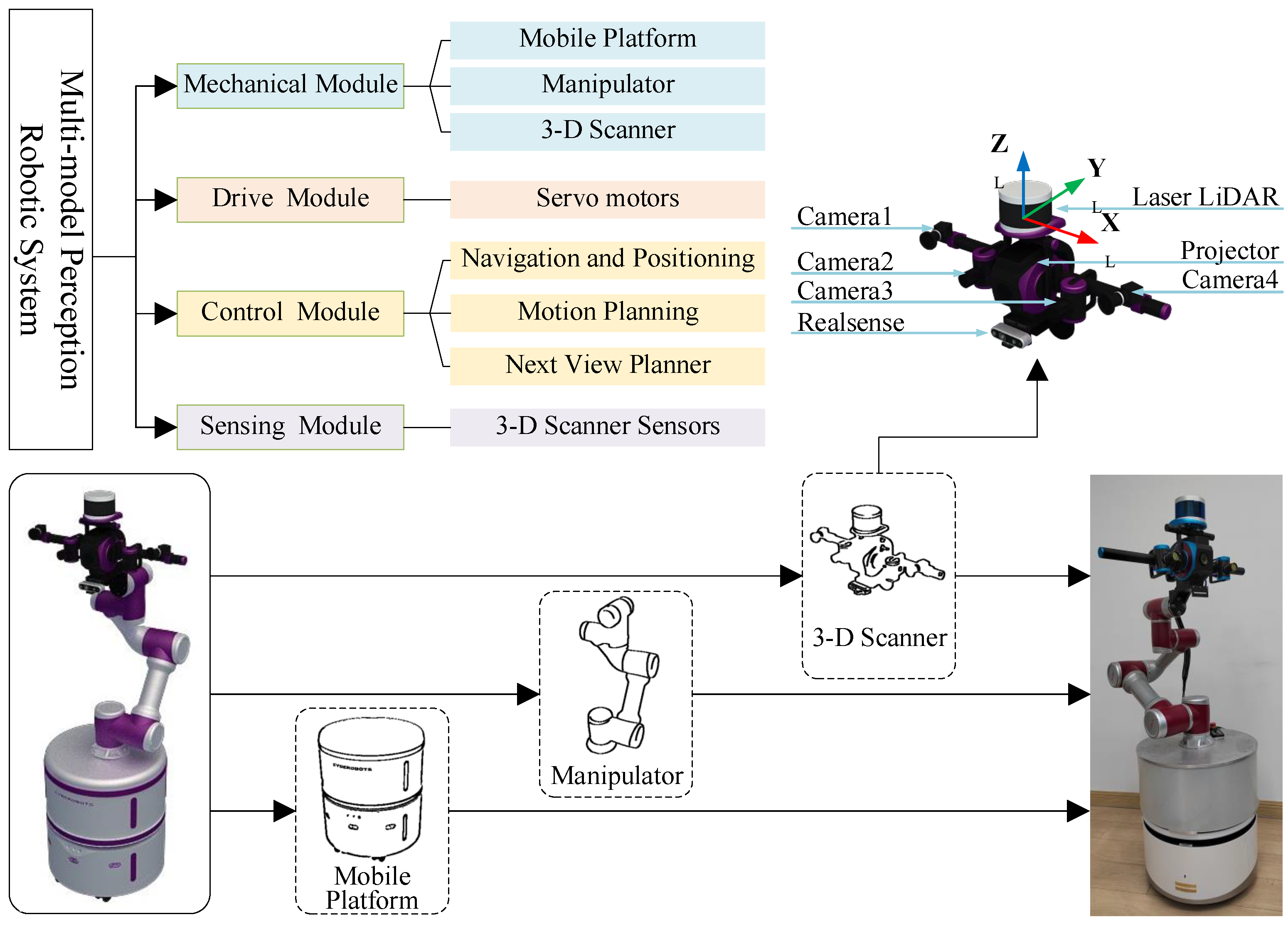
3. Robotic Multi-Model Perception System (RMMP)

3.1. Robotic System Overall Structure

The robotic multi-model perception system (RMMP) proposed in this paper is made up of four parts: a mechanical module, driving module, control module, and sensing module. The mechanical module includes a mobile platform, a manipulator, and a 3-D scanner; the drive module consists of several DC servo motors; the control module includes three parts: navigation and positioning, a next frame planner, and motion planning; and the sensing module consists of sensors belonging to a 3-D scanner. All of these modules are shown in the upper left of Figure 5.

3.2. Mechanical Module and Self-Designed Scanner

The mechanical module in RMMP contains the mobile platform, manipulator, and 3-D scanner. The mobile platform is responsible for the plane movement of the robot system in 3-D space, which has the advantage of an unlimited movement range. The manipulator is responsible for the 3-D movement of the end scanner in space, which can ensure that the scanner makes a flexible movement in 3-D space. Moreover, the 3-D scanner is responsible for the data acquisition of the object to be scanned.
Among them, the 3-D scanner is a novel self-designed platform, as shown in the upper right of Figure 5. The designed scanner has an axisymmetric structure with a projector in the center that can be specified to project structured light. The projector has two binocular vision systems, named as BVS1 and BVS2, respectively. The BVS1 is made up of Camera1 and Camera4, and the BVS2 is made up of Camera2 and Camera3. LiDAR is on the top of projector, and Realsense is beneath the projector.
For small-sized objects, we used the binocular systems made up of Camera2 and Camera3; in addition, the projector and Realsense were chosen to assist in data perception. For medium and large objects, the binocular systems made up of Camera1 and Camera4 were selected; in additoin, LiDAR was used to collect the object point cloud data. Throughout the 3-D scanning process, the scanner attitude information can be collected using the inertial measurement unit (IMU) integrated in Realsense.

3.3. Control Module

The control module of RMMP is the key part to accomplish the autonomous scanning task, as shown in Figure 6. The control module designed in this paper contained navigation and positioning, the next view planner, and motion planning. Navigation and positioning were used to calculate the robot pose, obstacle avoidance, and other functions. The next view planner was used to calculate the ideal shooting pose for the next frame, and motion planning was used to calculate and control the robotic system movement.

4. Experiment

In order to verify the effectiveness of the RMMP system and the method described above, we took the real natural scene as a 3-D scanning experimental object and carried out the 3-D scanning experiment.

4.1. Experimental Environment

The hardware composition of the RMMP system is shown in Figure 5. The mobile platform takes differential two wheel drive mode, the mechanical manipulator adopts 6-DOF serial flexible mechanical mode, and the end of the mechanical manipulator controls the self-developed 3-D scanner device. Moreover, the system was equipped with a minicomputer to control the system. Therefore, the robot system can improve the flexibility and automation level of 3-D scanning.

4.2. Task Workflow

The workflow of the 3-D scanning and reconstruction task is shown in Figure 7, and is demonstrated as follows:
(1) First, preset the path of the mobile platform according to the shape of the object to be scanned. For example, for a car, a circular path or elliptical path needs to be preset to control the movement of the mobile platform; for a square column, a square path is needed; for a small object, directly presetting a circular path is correct. During the movement of the robot in the preset path, the LiDAR and Realsense located on the scanner begin to work. After the preset path is completed, we can derive L, W, and n;
(2) Based on the data obtained in the previous step, path planning is started to acquire image data. In this process, not only do the laser radar and depth camera start to work, but BVS1, BVS2, or both also begin to work. After the path is completed, at a distance of h, a set of pictures of the scanned object can be obtained. Compared with using images obtained by the traditional method of path planning, a better 3-D reconstruction can be realized by this set of images;
(3) Decrease the distance h and scan the object again. A better 3-D reconstruction can be obtained by using this set of images and images formed by process (2);
(4) Judge the reconstruction result of the object. Paper [43] gives an evaluation method. If the reconstruction result is reasonable, we can move to the next process. However, if the result is unsatisfactory, repeat process (3) until the reconstruction effect of the object reaches the requirements;
(5) Return the robot to the starting point and carry out the post-processing of the 3-D model. After the post-processing, if holes and other problems exist in the model, repeat process (3), (4), and (5) until the 3-D model meets the requirements;
(6) Finish the experiment.

4.3. Multi-Model Data Perception

In this paper, a real natural scene was scanned and reconstructed in three dimensions. Specifically, for the flower bed and the pine tree inside, a suborbicular motion path was preset. During the motion of the RMMP system, the LiDAR and Realsense located on the scanner started to work. After completing the preset path, L, W, and n were obtained. Considering the actual situation, we chose 2.5 m and 2 m as the equidistant constraint h, combined with kinematic constraints, to generate the planning results of Path 1 and Path 2, respectively. The path planning effect of the RMMP system in the real scene is shown in Figure 8. Table 1 shows the relevant experimental data information of different paths.
Table 1 shows the relevant experimental data information of different paths. From Table 1, it can be seen that the effect of path planning is significantly improved when photogrammetric constraints are added (both of the path lengths under constraints are smaller than the preset path length), and the effect of path planning is further improved with the reduction in equidistant constraint h. In addition, the effect of path planning can be seen intuitively from Figure 8. Furthermore, from the triangular facet data in Table 1, it can be seen that the effect of reconstruction is further improved with the reduction in equidistant constraint h.

4.4. Three-Dimensional Real Scene Reconstruction

After using RMMP system for data perception, the collected data were used in 3-D reconstruction. The 3-D reconstruction result under different h is shown in Figure 9. As the left side of Figure 9 shows, the pictures taken in the equidistant constraint h, the reconstructed model has an uneven surface and bulging edge; when distance h is reduced, the reconstructed effect is better handled for both the plane and the edge. The right side of Figure 9 shows the reconstructed results, demonstrating a better performance.

5. Conclusions

This paper introduced a RMMP system, focusing on the path-planning-based next view planner and inverse kinematics constraints. Under photogrammetric constraints, the proposed next view planner can figure out the problems of image deformation and resolution loss caused by the shape change of the objects to be reconstructed. In addition, the proposed inverse kinematics constraints make the robot able to reach an ideal pose. Compared with the traditional scanning method, the proposed robotic system improves the 3-D scanning automation and efficiency. In the RMMP system, the mobile platform was used for plane movement in two-dimensional space, and the flexible manipulator was used to ensure the motion ability of the scanner in 3-D space. In addition, the designed scanner can collect multi-model information of different-size objects. Preliminary experiments show that the correctness of the proposed inverse kinematics and the rationality of the proposed next view planner provide a guarantee for the robot to complete automatic data acquisition.
It must be pointed out that the proposed RMMP system has the characteristics of a high efficiency and universality, as well as being very suitable for the 3-D data acquisition of large scenes or objects. The future work will focus on further improving the level of the automation of the robotic system and achieving efficient 3-D reconstruction.

Author Contributions

Conceptualization, C.F., H.W., Z.C., X.C. and L.X.; data curation, C.F. and Z.C.; funding acquisition, H.W., X.C. and L.X.; methodology, C.F., H.W., Z.C., X.C. and L.X.; project administration, H.W., X.C. and L.X.; supervision, H.W., X.C. and L.X.; validation, C.F. and Z.C.; writing—original draft, C.F., H.W., X.C. and L.X.; writing—review and editing, C.F., H.W., X.C. and L.X. All authors have read and agreed to the published version of the manuscript.

Funding

This work was supported in part by the Natural Science Foundation of China (Grants Nos. 61973173, 91848203), the Technology Research and Development Program of Tianjin (Grant Nos. 20YFZCSY00830, 18ZXZNGX00340), and Open Fund of Civil Aviation Smart Airport Theory and System Key Laboratory of Civil Aviation University of China (Fund No. SATS202204).

Institutional Review Board Statement

Not applicable.

Informed Consent Statement

Not applicable.

Data Availability Statement

Not applicable.

Conflicts of Interest

The authors declare no conflict of interest.

References

  1. Chong, S.; Pan, G.T.; Chin, J.; Show, P.L.; Yang, T.C.K.; Huang, C.M. Integration of 3D printing and Industry 4.0 into engineering teaching. Sustainability 2018, 10, 3960. [Google Scholar] [CrossRef] [Green Version]
  2. Hao, B.; Lin, G. 3D printing technology and its application in industrial manufacturing. In Proceedings of the IOP Conference Series: Materials Science and Engineering; IOP Publishing: Bristol, UK, 2020; Volume 782, p. 022065. [Google Scholar]
  3. Wang, P.; Wu, P.; Wang, J.; Chi, H.L.; Wang, X. A critical review of the use of virtual reality in construction engineering education and training. Int. J. Environ. Res. Public Health 2018, 15, 1204. [Google Scholar] [CrossRef] [PubMed] [Green Version]
  4. Li, Y. Film and TV Animation Production Based on Artificial Intelligence AlphaGd. Mob. Inf. Syst. 2021, 2021, 1104248. [Google Scholar] [CrossRef]
  5. Zhao, D.; Li, Y.; Liu, Y. Simulating dynamic driving behavior in simulation test for unmanned vehicles via multi-sensor data. Sensors 2019, 19, 1670. [Google Scholar] [CrossRef] [Green Version]
  6. Hou, M.; Yang, S.; Hu, Y.; Wu, Y.; Jiang, L.; Zhao, S.; Wei, P. Novel method for virtual restoration of cultural relics with complex geometric structure based on multiscale spatial geometry. Isprs Int. J.-Geo-Inf. 2018, 7, 353. [Google Scholar] [CrossRef] [Green Version]
  7. Zhao, S.; Hou, M.; Hu, Y.; Zhao, Q. Application of 3D model of cultural relics in virtual restoration. Int. Arch. Photogram. Remote Sens Spat. Inf. Sci. 2018, 42, 2401–2405. [Google Scholar] [CrossRef] [Green Version]
  8. Lozano, M.T.U.; D’Amato, R.; Ruggiero, A.; Manzoor, S.; Haro, F.B.; Méndez, J.A.J. A study evaluating the level of satisfaction of the students of health sciences about the use of 3D printed bone models. In Proceedings of the Sixth International Conference on Technological Ecosystems for Enhancing Multiculturality, Salamanca, Spain, 24–26 October 2018; pp. 368–372. [Google Scholar]
  9. Chabra, R.; Lenssen, J.E.; Ilg, E.; Schmidt, T.; Straub, J.; Lovegrove, S.; Newcombe, R. Deep local shapes: Learning local sdf priors for detailed 3d reconstruction. In Proceedings of the European Conference on Computer Vision, Glasgow, UK, 23–28 August 2020; pp. 608–625. [Google Scholar]
  10. Tian, X.; Liu, R.; Wang, Z.; Ma, J. High quality 3D reconstruction based on fusion of polarization imaging and binocular stereo vision. Inf. Fusion 2022, 77, 19–28. [Google Scholar] [CrossRef]
  11. Gallo, A.; Muzzupappa, M.; Bruno, F. 3D reconstruction of small sized objects from a sequence of multi-focused images. J. Cult. Herit. 2014, 15, 173–182. [Google Scholar] [CrossRef]
  12. De Paolis, L.T.; De Luca, V.; Gatto, C.; D’Errico, G.; Paladini, G.I. Photogrammetric 3D Reconstruction of Small Objects for a Real-Time Fruition. In Proceedings of the International Conference on Augmented Reality, Virtual Reality and Computer Graphics; Springer: Berlin/Heidelberg, Germany, 2020; pp. 375–394. [Google Scholar]
  13. Cui, B.; Tao, W.; Zhao, H. High-Precision 3D Reconstruction for Small-to-Medium-Sized Objects Utilizing Line-Structured Light Scanning: A Review. Remote Sens. 2021, 13, 4457. [Google Scholar] [CrossRef]
  14. Schöps, T.; Sattler, T.; Häne, C.; Pollefeys, M. 3D Modeling on the Go: Interactive 3D Reconstruction of Large-Scale Scenes on Mobile Devices. In Proceedings of the 2015 International Conference on 3D Vision, Lyon, France, 19–22 October 2015; pp. 291–299. [Google Scholar]
  15. Kähler, O.; Prisacariu, V.A.; Murray, D.W. Real-time large-scale dense 3D reconstruction with loop closure. In Proceedings of the European Conference on Computer Vision, Amsterdam, The Netherlands, 11–14 October 2016; pp. 500–516. [Google Scholar]
  16. Schöps, T.; Sattler, T.; Häne, C.; Pollefeys, M. Large-scale outdoor 3D reconstruction on a mobile device. Comput. Vis. Image Underst. 2017, 157, 151–166. [Google Scholar] [CrossRef]
  17. Kim, H.; Guillemaut, J.Y.; Takai, T.; Sarim, M.; Hilton, A. Outdoor dynamic 3-D scene reconstruction. IEEE Trans. Circuits Syst. Video Technol. 2012, 22, 1611–1622. [Google Scholar] [CrossRef] [Green Version]
  18. Xu, Z.; Kang, R.; Lu, R. 3D reconstruction and measurement of surface defects in prefabricated elements using point clouds. J. Comput. Civ. Eng. 2020, 34, 04020033. [Google Scholar] [CrossRef]
  19. Guan, J.; Yang, X.; Ding, L.; Cheng, X.; Lee, V.C.; Jin, C. Automated pixel-level pavement distress detection based on stereo vision and deep learning. Autom. Constr. 2021, 129, 103788. [Google Scholar] [CrossRef]
  20. Hall-Holt, O.; Rusinkiewicz, S. Stripe boundary codes for real-time structured-light range scanning of moving objects. In Proceedings of the Eighth IEEE International Conference on Computer Vision, ICCV 2001, Vancouver, BC, Canada, 7–14 July 2001; Volume 2, pp. 359–366. [Google Scholar]
  21. Percoco, G.; Salmerón, A.J.S. Photogrammetric measurement of 3D freeform millimetre-sized objects with micro features: An experimental validation of the close-range camera calibration model for narrow angles of view. Meas. Sci. Technol. 2015, 26, 095203. [Google Scholar] [CrossRef] [Green Version]
  22. Li, W.; Zhou, L. A rotary vision system for high-precision measurement over large size. J. Mod. Opt. 2022, 69, 347–358. [Google Scholar] [CrossRef]
  23. Straub, J.; Kerlin, S. Development of a large, low-cost, instant 3D scanner. Technologies 2014, 2, 76–95. [Google Scholar] [CrossRef] [Green Version]
  24. Zeraatkar, M.; Khalili, K. A fast and low-cost human body 3D scanner using 100 cameras. J. Imaging 2020, 6, 21. [Google Scholar] [CrossRef] [Green Version]
  25. Yin, S.; Ren, Y.; Guo, Y.; Zhu, J.; Yang, S.; Ye, S. Development and calibration of an integrated 3D scanning system for high-accuracy large-scale metrology. Measurement 2014, 54, 65–76. [Google Scholar] [CrossRef]
  26. Du, H.; Chen, X.; Xi, J.; Yu, C.; Zhao, B. Development and verification of a novel robot-integrated fringe projection 3D scanning system for large-scale metrology. Sensors 2017, 17, 2886. [Google Scholar] [CrossRef] [PubMed] [Green Version]
  27. Zhen, W.; Hu, Y.; Liu, J.; Scherer, S. A joint optimization approach of lidar-camera fusion for accurate dense 3-d reconstructions. IEEE Robot. Autom. Lett. 2019, 4, 3585–3592. [Google Scholar] [CrossRef]
  28. Zhen, W.; Hu, Y.; Yu, H.; Scherer, S. LiDAR-enhanced structure-from-motion. In Proceedings of the 2020 IEEE International Conference on Robotics and Automation (ICRA), Paris, France, 31 May–31 August 2020; pp. 6773–6779. [Google Scholar]
  29. Shi, J.; Sun, Z.; Bai, S. Large-scale three-dimensional measurement via combining 3D scanner and laser rangefinder. Appl. Opt. 2015, 54, 2814–2823. [Google Scholar] [CrossRef] [PubMed]
  30. Wang, J.; Tao, B.; Gong, Z.; Yu, S.; Yin, Z. A mobile robotic measurement system for large-scale complex components based on optical scanning and visual tracking. Robot. Comput. Integr. Manuf. 2021, 67, 102010. [Google Scholar] [CrossRef]
  31. Wang, J.; Gong, Z.; Tao, B.; Yin, Z. A 3-D Reconstruction Method for Large Freeform Surfaces Based on Mobile Robotic Measurement and Global Optimization. IEEE Trans. Instrum. Meas. 2022, 71, 1–9. [Google Scholar] [CrossRef]
  32. Zhou, Z.; Liu, W.; Wang, Y.; Yue, Y.; Zhang, J. An accurate calibration method of a combined measurement system for large-sized components. Meas. Sci. Technol. 2022, 33, 095013. [Google Scholar] [CrossRef]
  33. Zhou, Z.; Liu, W.; Wang, Y.; Yu, B.; Cheng, X.; Yue, Y.; Zhang, J. A combined calibration method of a mobile robotic measurement system for large-sized components. Measurement 2022, 189, 110543. [Google Scholar] [CrossRef]
  34. Zhang, X.; Scholz, M.; Reitelshöfer, S.; Franke, J. An autonomous robotic system for intralogistics assisted by distributed smart camera network for navigation. In Proceedings of the 2018 IEEE 14th International Conference on Automation Science and Engineering (CASE), Munich, Germany, 20–24 August 2018; pp. 1224–1229. [Google Scholar]
  35. Schmid, L.; Pantic, M.; Khanna, R.; Ott, L.; Siegwart, R.; Nieto, J. An efficient sampling-based method for online informative path planning in unknown environments. IEEE Robot. Autom. Lett. 2020, 5, 1500–1507. [Google Scholar] [CrossRef] [Green Version]
  36. Naazare, M.; Rosas, F.G.; Schulz, D. Online Next-Best-View Planner for 3D-Exploration and Inspection With a Mobile Manipulator Robot. IEEE Robot. Autom. Lett. 2022, 7, 3779–3786. [Google Scholar] [CrossRef]
  37. Deng, D.; Duan, R.; Liu, J.; Sheng, K.; Shimada, K. Robotic exploration of unknown 2d environment using a frontier-based automatic-differentiable information gain measure. In Proceedings of the 2020 IEEE/ASME International Conference on Advanced Intelligent Mechatronics (AIM), Boston, MA, USA, 6–9 July 2020; pp. 1497–1503. [Google Scholar]
  38. Dai, A.; Papatheodorou, S.; Funk, N.; Tzoumanikas, D.; Leutenegger, S. Fast frontier-based information-driven autonomous exploration with an mav. In Proceedings of the 2020 IEEE International Conference on Robotics and Automation (ICRA), Paris, France, 31 May–31 August 2020; pp. 9570–9576. [Google Scholar]
  39. Wang, H.; Zhang, S.; Zhang, X.; Zhang, X.; Liu, J. Near-optimal 3-D visual coverage for quadrotor unmanned aerial vehicles under photogrammetric constraints. IEEE Trans. Ind. Electron. 2021, 69, 1694–1704. [Google Scholar] [CrossRef]
  40. Di Franco, C.; Buttazzo, G. Coverage path planning for UAVs photogrammetry with energy and resolution constraints. J. Intell. Robot. Syst. 2016, 83, 445–462. [Google Scholar] [CrossRef]
  41. Dai, R.; Fotedar, S.; Radmanesh, M.; Kumar, M. Quality-aware UAV coverage and path planning in geometrically complex environments. Ad. Hoc. Netw. 2018, 73, 95–105. [Google Scholar] [CrossRef]
  42. Xing, C.; Wang, J.; Xu, Y. Overlap analysis of the images from unmanned aerial vehicles. In Proceedings of the 2010 International Conference on Electrical and Control Engineering, Wuhan, China, 25–27 June 2010; pp. 1459–1462. [Google Scholar]
  43. Li, Y.; Wang, H.; Zhang, X. Dense Points Aided Performance Evaluation Criterion of Human Obsevation for Image-based 3D Reconstruction. In Proceedings of the 2020 10th Institute of Electrical and Electronics Engineers International Conference on Cyber Technology in Automation, Control, and Intelligent Systems (CYBER), Xi’an, China, 10–13 October 2020; pp. 246–251. [Google Scholar]
Figure 1. The robotic system proposed in this paper improves the automation of 3-D scanning and enables compatible scanning of different-size objects, especially providing an autonomous solution for 3-D scanning of large scenes or objects. The solution liberates people from a great many instances of repetitive mechanical labor. Moreover, the path planning based on photogrammetric constraints makes the data acquisition process more efficient and the collected data more effective.
Machines 11 00026 g001
Figure 2. Schematic diagram of photogrammetric constraints and path planning. X represents a series of three-dimensional spatial points at which the camera is shooting. h represents the constant distance between the camera and the center of the camera footprint, where the orientation of the camera is perpendicular to the fitted plane. In addition, σ 0 and σ 1 denote the horizontal and vertical overlapping rates.
Machines 11 00026 g002
Figure 3. The next view planner(I) shows fitting line processes. After the rotation and angle segmentation of the original data, further handling the data, and then fitting the straight line.
Machines 11 00026 g003
Figure 4. The next view planner(II) shows fitting plane processes. After fitting straight line, the frontal and equidistant constraints are used to fit plane and calculate ideal shooting pose, and the pose is then converted to the L coordinate system.
Machines 11 00026 g004
Figure 5. The framework of the robotic multi-model perception system (RMMP). This paper proposes a novel design of scanner and robotic system for covering scanning tasks. The scanner is a self-developed platform with an axisymmetric structure, including 4 cameras, 1 projector, 1 LiDAR, and 1 Realsense. The scanner coordinate system coincides with the end of the manipulator coordinate system. The base of the manipulator and the mobile platform are fixed by rigid connection; in addition, the scanner and the end of the manipulator are also fixed by rigid connection.
Machines 11 00026 g005
Figure 6. Flow chart of the control module. The module inputs LiDAR point cloud data or Realsense point cloud data for navigation and positioning module and next view planner module simultaneously. The navigation and positioning module calculates the current pose, the next view planner module calculates the ideal pose at the next view, and the motion planning module uses the current pose and the ideal pose at the next view for motion planning.
Machines 11 00026 g006
Figure 7. Flow chart of 3-D scanning task. An example is given to illustrate how the RMMP system completes an overall 3-D scanning task.
Machines 11 00026 g007
Figure 8. The path planning of the RMMP system in the real scene experiment. The red circle is the preset path, the green represents the planned path under the constraint h, and the blue means the planned path under the constraint of decreased h. It can be seen that the proposed method improves the effectiveness of path planning.
Machines 11 00026 g008
Figure 9. Three-dimensional reconstruction results under different constraint h.
Machines 11 00026 g009
Table 1. Experimental data of different paths.
Num of X i Constrainst h (m)Path Length (m) L × W  (m)Triangular Facet
Preset path5025.40
Path1472.521.73 6.49 × 2.88 1,703,424
Path244218.47 6.30 × 2.78 2,982,178
Disclaimer/Publisher’s Note: The statements, opinions and data contained in all publications are solely those of the individual author(s) and contributor(s) and not of MDPI and/or the editor(s). MDPI and/or the editor(s) disclaim responsibility for any injury to people or property resulting from any ideas, methods, instructions or products referred to in the content.

